1
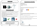
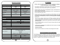
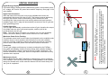
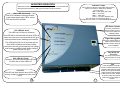
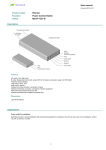
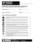
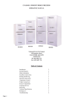
INSTRUCTION MANUAL
INVERTER WITH ENERGY METER
Doc No A340-D05-V22-Q2
03/12
WELCOME
Latronics products are all proudly designed, engineered and
manufactured in Australia. As a specialist sine wave inverter company
we produce Inverters for a diverse range of applications such as;
mining, railways, telecommunications, marine, remote power, motor
homes, and other industrial or commercial installations.
In order to produce the most reliable products available, Latronics
Inverters have been designed to endure the most rugged terrain and
the harshest conditions across the Australian continent.
All products are engineered using the latest high quality components
and manufactured to stringent quality standards, thus ensuring
Latronics customers all enjoy many years of trouble free operation.
It is important to us at Latronics, that our clients enjoy the maximum
benefits from our Inverters in a safe and productive environment. So
we strongly advise that you read through the next few pages of this
manual, which explains all the modes of operation and relevant safety
precautions for your new Power Inverter.
NZ Distributor:
1 Heremai Street, Henderson, Auckland, New Zealand, 0612
PO Box: 19 501, Auckland, New Zealand, 1746
Phone: +64 9 835 0700, Free call NZ: 0800 654 668
Fax: +64 9 837 3446, www.innovative.co.nz
TABLE OF CONTENTS
PAGE
INSTALLATION
2
DC WIRING / DC EARTHING
3
AC WIRING
5
WIRING DIAGRAMS
7
INVERTER OPERATION
10
SPECIAL FEATURES
12
DIP SWITCH SETTINGS
13
SOLAR INPUT CONFIGURATION
14
FAULT FINDING
15
RADIO FREQUENCY INTERFERENCE
16
WARRANTY CONDITIONS
17
TECHNICAL SPECIFICATIONS
18
DECLARATION OF CONFORMITY
19
INSTALLATION
DECLARATION OF CONFORMITY
! Grid Interactive Solar Systems have become increasingly popular in recent
years. These systems do not necessarily require batteries for storage and
therefore can have a very simple configuration.
Mains
Photovoltaic Cells
PV Edge
Manufacturer:
Latronic Sunpower Pty Ltd
105 Grigor St West
Moffat Beach Industrial Park
Caloundra Queensland 4551
Australia
Declare that the PV Edge grid connected Inverter Model No. PVE1200 and
PVE2500 conform to the requirements of following standards
BEFORE INSTALLATION
! Ensure the Inverter has not been damaged in transit.
! The unit must be placed in a well ventilated and protected area, not exposed
to the open environment, and free from contaminates (i.e. exhaust gases,
sea air, dust etc.).
! The PV Edge is designed for indoor installation in a suitable location where
ambient temperature will not exceed rated values.
! If the PV Edge is to be installed outdoors, please use the Latronics Outdoor
Enclosure (Part no: OE)
! The Inverter can be mounted horizontal on table or floor. The Inverter can
also be mounted on a wall, taking note of the sticker being the correct
orientation.
EN61000-6-1
EN61000-6-3
EN55014
AS1044
EN60335-1
AS3100
AS4777
And therefore conform to the regulations of the EC directives
Directive 2004/108/CE (EMC directive), Directive 2006/95/CE (low Voltage
Directive)
Date that CE marking was first affixed 2007
Also conforms to the regulations of C-tick mark for Australian emission standards
Australian Safety Certificate approval number CS06713V
All products are manufactured with full traceability in accordance with the
Quality System Requirements of AS/NZS ISO 9002
Signed
It is important that all wiring in the installation complies with the relevant
standards such as AS4777 and AS3000 .
Any work carried out is to be preformed by
Qualified and Licensed personnel.
2
William Pettit
Electronic Engineer
th
7 Feb 2009
19
DC WIRING
SPECIFICATIONS
Model
PVE1200
PVE2500
Maximum Solar Input Power
1600W
3100W
Maximum DC Input Current
Maximum DC Input Voltage
Maximum Power Point
Tracking Range
Ideal Operating Window
(Array VOC)
Automatic Turn ON (PV
Mode)
Automatic Turn ON (Battery
mode)
Starting Operation
Reverse Polarity Protection
25A
103V
25A
206V
54VDC - 100VDC
108VDC - 200VDC
75-92VDC
150-185VDC
70VDC
140VDC
54VDC
108VDC
Check solar array will not exceed inverter’s maximum voltage rating
of 103V (PVE1200) or 206V (PVE2500)
Input Data
10W
Short Circuit Diode Across DC Input Terminals
Output Data
Output Power
Output Voltage Range
Output Frequency
Peak Efficiency
Night Time Power
Consumption
Input/Output Isolation
Operating Temperature
Anti islanding Protection
Wall Mount Enclosure
Dimensions
Weight
Connections
Warranty
* A 48V nominal solar array at a temperature of 25°C should have an open
circuit voltage less than 92V
* A 96V nominal solar array at a temperature of 25°C should have an open
circuit voltage less than 185V
* If other sources of DC input are required e.g. wind turbines, micro hydro
turbines etc. A battery bank or Latronics Turbine Controller (see pg 9) will
be required with the Maximum Power Point Tracking (MPPT) disabled
(see pg 13).
*
The DC input voltage is stated on the PV Edge compliance label and the
technical specifications sheet within this manual. Check that the input
voltage is within the required limits and does not exceed the maximum
limit (see pg 18).
*
Recommended cable size for the DC Input is 6sqmm with an insulation
rating of 0.6/1KV.
*
A DC isolator is required to be installed next to the inverter to isolate the
inverter for maintenance.
*
Observe Polarity.
*
Ensure the DC Isolators are off when connecting the DC Leads
1100W at 50ºC (1250W Max) 2100W at 50ºC (2500W Max)
205 - 265 Vac
50Hz tolerance +/- 1Hz
94%
95%
NIL. Automatically Disconnects from AC Grid
3500V via Toroidal Transformer
-10ºC to 50ºC
Over/under voltage, Over/under frequency, Active phase shift
General Data
Status Indicators
* The inverter is designed to operate with a 48V nominal solar panel array
(PVE1200) or 96V nominal solar panel array (PVE2500).
Output power in 25% Increments
Grid Monitoring - Stability check
Solar Input ON
Grid Fault
Overload
LCD Meter - Power, Voltage, Current, Power Factor,
Powder Coated Aluminum
330mm H x 296mm W x
370mm H x 386mm W x
150mm D
180mm D
11 kg
22 kg
AC/DC Pluggable Connectors
5 years
18
POSITIVE/NEGATIVE EARTHING
The PV Edge inverter is suitable for use with solar arrays that require positive
or negative earthing. Due to the inverter’s galvanic isolation between AC and
DC inputs no additional modifications are required. Simply connect the
positive or negative of the solar array to the system earth.
3
WARRANTY TERMS AND CONDITIONS FOR AUSTRALIA
SBS50 CONNECTOR WIRING
The inverter comes with an SBS50 connector panel mounted on the
case. To assemble the connecting partner, take the SBS50 connector
and follow the instructions below.
1. Remove the lugs with a screwdriver from the plug by inserting into
the end and pressing down on the thin metal retaining strip.
Latronic Sunpower Pty Ltd (“Latronics”) provides the original purchaser of a Latronics product (“You”) with the following Limited Warranties as
set out in this warranty certificate, in addition to your rights and remedies under consumer law.
The Limited warranty periods of this inverter is 5 years. In all circumstances Latronics products are guaranteed from the date of purchase.
Part 1 - Warranty Descriptions
Part 2 – Returning a Latronics product for service under warranty.
Latronics warrants to You that our products are guaranteed against
defects in material or workmanship, when in normal use and
service.
If service is required contact your local supplier/installer or place of
purchase for advice.
To Claim Under Warranty:
What you must do
1.You should contact the Customer Care Centre on 1300 550
204. Product Model number and Serial number need to be readily
available to enable prompt processing.
1.For a Limited Warranty to apply the Registration Card must be
validly completed by You and returned, prior to the expiration of 3
months from the date of purchase.
+
-
2.You must provide proof of purchase.
3.Latronics recommends You keep your receipt as proof of
purchase, should any difficulties arise concerning the return of your
Registration Card.
2. First check no voltage is present on the cables, then strip back
10mm of cable (Recommended Cable: 6sqmm or bigger). Insert the
stripped DC cable into the metal insert and crimp shut.
Crimp Shut
3. Push cable lugs into the main body until clipped in, taking care with
polarity, which is marked on the connector housing by + & - .
-
+
NB. This is a touch proof connector as per UL 1977, Section10.2.
The DC connector can be disconnected under load.
4
Exclusions:
For the avoidance of doubt, the Latronics product warranties
provided herein do not cover damage, malfunctions or service
failures caused by, amongst other things:
•
Unauthorized opening of the products, repair,
alteration or substitution of nonstandard parts;
•
Incorrect design and/or installation of ‘balance
of system’;
•
Acts of god, accident or similar cause;
•
Failure to follow Latronics installation, operation
or maintenance instructions;
•
Abuse, misuse or negligent acts;
•
Power failure surges, lightning, fire, flood, pest
damage, accidental breakage, actions of third
parties and other events or accidents outside
Latronics’ reasonable control and not arising
from normal operating conditions;
•
Suitably qualified personnel not carrying out all
AC and DC permanent wiring in accordance
with relevant wiring rules.
Products supplied by Latronics, or Latronics agents are supplied
under the express condition that no responsibility is implied or
accepted by Latronics for any damage to any appliance,
equipment or property used in combination with the correct
operation of a Latronics product.
All conditions and warranties expressed or implied by statute,
common law, equity, trade, custom, usage, or otherwise
howsoever are hereby expressly excluded to the maximum extent
permitted by law. Where so permitted, the liability of Latronics for a
breach of condition or warranty that cannot be excluded is limited
(at Latronics option) to the replacement or repair of the goods or
of acquiring equivalent goods or the cost of replacing or repairing
the goods or of acquiring equivalent goods.
Latronics does not undertake any commitment to guarantee
continuity of supply in the case of obsolescence. In addition,
Latronics reserves the rights to change its standard product range
or specification of any model subsequently without notice and no
liability as a result of these occurrences will be accepted.
2.If, after investigation, the Customer Care Centre determines the
product is or may be defective in material or workmanship and
within the warranty period, they will issue instructions on how to
proceed with return and shipping to Latronics.
3.When packaging a Latronics product for return appropriate
measures must be taken by You to ensure the products are safely
packed for transit. Products damaged in transit due to inadequate
packaging will be void of warranty.
4.If the product manual has a Warranty Return Form included, this
form should be completed and accompany products being
returned.
5.If, as a result of further investigation by or on behalf of Latronics,
such a defect is confirmed, then Latronics must, at its sole
election, either repair or replace your Latronics product. Latronics
will also, at their discretion, determine the most appropriate
means to return any Warranty repairs (or replacements) to You in a
timely manner.
Part 3 - General Information
Replacement of any part or labour involved in repairs will not have
the effect of extending the original period of the Limited Warranty
of the goods. Any faulty part replaced under Limited Warranty
becomes the property of the Company for purpose of
examination and claim under proprietary warranty.
Under these product warranties, Latronics is not responsible for and
you hereby agree to bear any costs associated with removal,
transportation or reinstallation of your Latronics products or any
peripheral components in the balance of any system used in
conjunction with Latronics products.
Products returned to Latronics without prior authorisation will be
returned to the sender at their expense.
All Warranty repairs are completed ex-factory to ensure
•
Fast service turn around time
•
Specialised, factory trained technicians
•
All required components are available (except
in the case of obsolescence)
•
Thorough testing to all Latronics specifications
•
Dedicated test equipment
•
Upgrades/updates to latest Latronics
standards/specifications (where applicable).
Our goods come with guarantees that cannot be excluded under the Australian Consumer Law. You are entitled to a replacement or
refund for a major failure and compensation for any other reasonably foreseeable loss or damage. You are also entitled to have the goods
repaired or replaced if the goods fail to be of acceptable quality and the failure does not amount to a major failure.
17
RADIO FREQUENCY INTERFERENCE
AC WIRING
Radio Frequency Interference (RFI) is a phenomenon that exists in modern
society and is a problem in many areas of electronics. For Inverter users,
RFI normally presents itself in the form of static and/or interference when
listening to an AM radio and in unusual cases may interfere with TV reception.
Both models require an external circuit breaker for protection of
inverter’s AC input. Usually mounted in main switchboard and/or next to the
inverter. The active and neutral of the AC output are electrically isolated from
the DC inputs and earth connections.
Over the years Latronics has continued to invest significant time and effort in
the reduction of RFI related emissions from the entire product range, so that
they comply with the appropriate International and/or Australian Standards.
Latronics Inverters have the AC output (active and neutral) floating with
respect to the DC and Earth. This configuration provides the highest degree
of safety and flexibility for installation wiring. The earth E is connected
internally to the Inverter case and is suitable for MEN wiring.
Even with this compliance, there are situations where RFI may still be a cause
for concern, and can differ greatly from installation to installation. Accordingly,
the following is a list of recommendations made to assist in the overall
reduction of RFI.
The unit is supplied with both male and female 20Amp Wieland Gesis
lockable AC connectors.
1.
Separate DC and AC wiring. Avoid running DC and AC cables in the
same conduits and/or cable trenches. It is strongly recommended that
DC and AC wiring be separated by the greatest distance possible. In
extreme cases, the use of shielded conduit may be necessary.
To install connectors read the following procedure.
Minimize length of DC cabling. DC cables can act as an aerial,
therefore all such cables should be kept as short as is practicable. For
best performance minimize DC cable length to Inverter and Batteries and
if possible avoid the use of auxiliary DC loads.
2. Test the wiring with a voltmeter to make sure no voltage is present.
2.
3.
4.
5.
240Vac Earth. For household installations, it is recommended that a
“good” Earth Stake is located as nearby the Inverter as is possible.
AM and HF Radios. These types of radio equipment inherently suffer
from all forms of RFI, especially when the received signal level is weak.
In such cases reception can sometimes be improved by relocation of the
radio itself, alternatively the use of an appropriate external antenna and
co-axial cable may be necessary. External antennas should be located
in a manner that ensures maximum signal strength whilst affording the
greatest possible distance away from the Inverter and Batteries.
Televisions. TV signals are transmitted as FM waveforms. This type of
signal fundamentally reduces the effects of RFI, therefore the use of a
good antenna and feeder cable is normally sufficient to ensure quality
reception. Locating the television as far as possible from the Inverter may
also improve picture clarity.
16
1. Turn external AC Circuit Breaker switch into OFF position and make
sure it cannot be switched back on.
3. Peel back 30mm of cable jacket and cut Active and Neutral cables
5mm shorter than Earth.
30mm
Round 2.5sqmm Twin & Earth Cable
Earth
4. Strip 5mm off all three cables.
5. Take the Wieland Gesis connector, disassemble into three main sections
and insert stripped wire through as shown below.
Socket
Main Body
5
Pressure Ring
FAULT FINDING
6. Connect the Active, Neutral and Earth cables as per diagram below.
Should the Inverter appear to be malfunctioning we suggest the following to
eliminate any external problems.
Socket
Neutral
L
N
Active
!
Turn the Inverter OFF by switching the External DC and AC isolators
OFF. Leave OFF for 60 seconds.
!
Reconnect the DC Solar Input by switching external DC Isolator ON. All
lights on the Inverter should come ON for 1 second at power up and
then go OFF. The 75% light should remain ON to indicate the Solar
Input is available. Solar Input voltage needs to be above the automatic
turn ON voltage, for the light to turn ON, see pg 18. If the light does not
illuminate check Solar Input for correct operation.
!
Next reconnect the AC grid by switching the external AC breaker ON.
After 20 seconds the 75% light should begin flashing to indicate Inverter
reconnecting to the AC grid. The light will flash for 60 seconds while the
PV Edge checks that the mains voltage and frequency are stable.
Should the light not begin flashing check if the AC grid is present.
!
After the 75% light stops flashing the Inverter will begin feeding power
into the AC Grid.
E
Earth
7. Push the socket back into the Main Body until it clips in.
8. Screw the Pressure Ring back in to form a tight seal.
9. Plug into PV Edge.
HELPFUL HINTS
To disconnect the plug, simply push the release clip in and unplug.
Note: The release clip section can be completely taken out if a lockable
connector is not desired.
Push to release
6
!
Make certain that you understand the operation of the Inverter.
!
Remember that it has automatic reconnection to the AC grid.
!
Make sure leads and terminals are not corroded, loose or faulty in any
way.
!
Make sure all external DC and AC isolators are reset properly. If unsure
switch OFF and ON again.
15
Import Meter
Grid Mains
Export Meter
10A
10A
Air Con
Stove
Lights
= Circuit Breaker
Values of Inverters output
14
Non-resettable kWh meter
(Optional)
A V kWh
Regulator
235.8
00125.6
Batteries
Note: To reset the Resettable kWh meter. Press on hold for 10sec
7
PVE1200 – 48V (min 200Ahrs)
PVE2500 – 96V (min 200Ahrs)
Instantaneous power that is being generated.
Resettable accumulative Power (kWh meter)
Output Voltage (V)
Output Current (A)
Output Frequency (Hz)
Output Power Factor
Legend
kW:
kWh:
V:
A:
F:
PF:
PV Edge
The PV Edge meter shows the following measurements on screen.
To scroll through the values Use the button below the screen.
Solar Panels
!
AC Transfer Switch
(ACTS-2)
Energy Meter
LS Inverter
All solar modules should be of the same type and brand. Therefore
the maximum power point and voltage variation with temperature are
consistent for all modules, which will ensure maximum system output.
(Example only)
!
Switchboard
Do not exceed recommended Maximum DC Input Power.
AC
!
DC
The DC input is suitable for connection to solar modules only, when
MPPT is enabled.
Battery Back-Up System
!
Power
http://www.innovative.co.nz/pdf/PVE_PanelSizing_details.pdf
Lights
To configure your panels with the PV Edge inverter please go to
Power
!
Hot Water
SOLAR INPUT CONFIGURATION
DIP SWITCH SETTINGS
Any work carried out on AC/Mains wiring is to be performed by Qualified And Licensed
personnel only.
WARNING:
The Inverter output is connected to mains electricity, thus it is important that all AC wiring complies
with the requirements of the relevant wiring standards, (AS3000, AS4777).
Import Meter
10A
PV Edge
Grid Mains
Legend
= Circuit Breaker
8
Export Meter
Air Con
Stove
Hot Water
Lights
Lights
Power
(Example only)
Solar Panels
Standard Grid Connect System
Switchboard
Power
Switch 1 -MPPT / Battery mode
In the ON position (default) the Maximum Power Point Tracking is enabled.
This is required when the DC input is Photovoltaic Solar Modules only.
In the OFF position the Maximum Power Point Tracking is disabled and the
voltage tracking will operate at a fixed voltage of 54V (PVE1200) or 108V
(PVE2500). This setting is required in a system where a 48V (PVE1200) or
96V (PVE2500) Battery Bank is required on the DC input.
Switch 2 - 50/60 Hz
In the ON position the Inverter is set for 60Hz operation.
In the OFF position (default) the Inverter is set for 50Hz operation.
Switch 3
(If Switch 1 OFF)
ON = Gel/SLA battery.
OFF = Flooded battery. (Default)
(If Switch 1 ON)
ON = 255VAC sustained operation
OFF= Sustained operation turned off
Switch 4
Must be in OFF position (default) for normal operation. The ON position is a
factory AC test setting.
Switch 5
Must be in the OFF position (default) for normal operation. The ON position
is a factory DC test setting.
Switch 6
DIP SWITCH LOCATION
Not used.
MAIN PCB
ON
123456
OFF
DIP Switch located on Main PCB
WARNING:
Due to dangerous voltages existing inside the unit, make sure
the external DC and AC solar isolators are turned off before
opening the unit. Only qualified Trades Persons are permitted to
adjust these settings.
13
12
3 Phase or DC Voltage
Maintenance Cycle
When in Battery mode (MPPT disabled) a maintenance cycle is performed
every 30 days. This is a short boost cycle for sealed batteries or an equalize
charge for flooded cells. In this mode the bottom LED will flash slowly until
the cycle is completed.
Turbine
Protection
The AC grid voltage and frequency is closely monitored by the PVEdge
along with anti islanding checks via active phase shifts. Isolation between
the DC input and AC output is achieved via the Toroidal Transformer. The
Inverter is fitted with a cooling fan, which is temperature controlled and only
operates when required.
Turbine
Controller
Maximum Power Point Tracking
The optimum power level from the solar input depends on the available solar
modules. Even in cloudy weather with fluctuations in the solar radiation
level, the PV Edge constantly monitors and tracks the optimum operating
point to ensure maximum power from the solar modules is achieved.
9
NOTE: PV Edge must be in Battery Mode. (See pg 13)
Turbine controller may require a dump load. (see Turbine Controller manual)
Parallel Operation
The PV edge automatically synchronizes to the AC grid, therefore the output
of multiple units can all be connected together, and they will all be
synchronized by the AC grid.
Note: The Solar inputs of multiple unit Inverters are not to be parallelled
unless used with a battery. Please contact Latronics for more details.
PV Edge
Night Time Disconnect
After dark when the solar input is no longer available the Inverter will
automatically disconnect from the AC grid. This feature ensures that during
the night, the Inverter cannot consume any power whatsoever while
remaining idle. Upon sunrise the next morning when solar input becomes
available again, the PV edge will automatically reconnect to the AC grid and
begin generating power.
Grid Mains
Digital Energy Display
The backlit energy display shows instantaneous power, accumulative power,
AC voltage, AC current, AC power factor and AC frequency. See page 14 for
more details.
The Latronics Turbine Controller utilizes the latest in micro-controller design to deliver a
stable and safe supply of power to the grid connect inverter. Designed specifically to
integrate with the PV Edge line of Latronics inverters, it allows battery-less grid
connection of wind and water turbines.
SPECIAL FEATURES
INVERTER OPERATION
When the Inverter is switched on all 4 LED'S light up for 1 second while the
microprocessor performs a start up and system check procedure.
100% LED (Overload)
This LED indicates overtemp/overload.
In this mode the all other LED’s will be
OFF and this LED will flash.
Indicator Lamps
The 4 LED’s on the front panel are dual purpose.
When in normal run mode they operate
as a bar graph
LED 4 -76%-100% (top Led).
LED 3 - 51%-75%.
LED 2 - 26%-50%.
LED 1 - 1%-25%. (Bottom Led).
If the Inverter were supplying 60% of
Full power then Led’s 1, 2 & 3 would be illuminated.
DC Solar Connector
For easy connection and
disconnection of DC Input
Power from Solar Panels
or Battery Bank.
75% LED(AC Grid)
This LED has 2 modes of operation.
This LED will be ON solid with all other LED’s off
when the solar input is present and the AC grid
is disconnected and/or awaiting reconnection.
Digital Energy Meter
Using the yellow button you are
able to scroll through the
different values. See page 14
for more details.
This LED will FLASH for 90 seconds with all
other LED’s off when the inverter initially
connects to the AC grid and performs a voltage
and frequency stability check before feeding
power into the AC grid.
Plug & Play AC
Connector
For easy connection and
disconnection to AC grid.
50% LED (AC Fault)
When an AC fault is present this LED will
FLASH and all other LED’s off
Fan
25% LED
This LED will flash with all other LED’s off
during a battery maintenance cycle (see
pg12).
10
11
If the temperature inside the
Inverter reaches preset levels, the
variable speed fan will switch on
initially in low speed and then into
higher speed if the temperature
continues to increase. Obstruction
of the air intake and output will
reduce the power rating of the
Inverter.