1
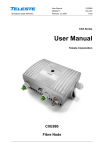
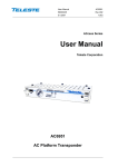
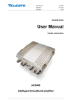
Broadband Cable Networks
User Manual
HDC100
59300202
Rev.004
10.2.2011
1(25)
HDO Series
User Manual
Teleste Corporation
HDC100
Controller Module
Broadband Cable Networks
User Manual
HDC100
59300202
Rev.004
10.2.2011
2(25)
Broadband Cable Networks
User Manual
HDC100
59300202
Rev.004
10.2.2011
3(25)
Contents
Introduction ........................................................................................................ 4
Parts and functions ........................................................................................... 5
Front and rear panel ............................................ Error! Bookmark not defined.
Installation ............................................................................................................ 6
Indicators ............................................................................................................. 7
Software .............................................................................................................. 8
Establishing connection ....................................................................................... 8
Enabling HDC100 SNMP proxy feature .............................................................. 8
Alarms / flags ....................................................................................................... 9
Viewer pages .................................................................................................... 10
Status ................................................................................................................. 10
HDO Devices ..................................................................................................... 11
Interfaces ........................................................................................................... 12
Monitoring .......................................................................................................... 14
SNMP ................................................................................................................ 18
NTP .................................................................................................................... 20
Properties .......................................................................................................... 21
Web user interface........................................................................................... 22
WebUI structure ................................................................................................. 22
SNMP proxy...................................................................................................... 24
Legal declarations ........................................................................................... 25
Broadband Cable Networks
User Manual
HDC100
59300202
Rev.004
10.2.2011
4(25)
Introduction
HDC100 is a controller module for HDO platform. It is installed into HDX002
installation frame. The unit enables gateway Ethernet connectivity to an HDO
system and allows remote management with CATVisor EMS system.
HDC100 can also act as an SNMP proxy server, which monitors all HDO
modules and thus creates a single access point for whole HDO system for 3rd
party EMS systems.
Broadband Cable Networks
User Manual
HDC100
59300202
Rev.004
10.2.2011
5(25)
Parts and functions
Front and rear panels
7911035
Figure 1. HDC100 Controller Module
1 & 2) Indicators: The front panel LED indicators display unit status. For more
information, see the ‘Indicators’ chapter.
3) Service port connector: For factory use only.
4 & 9) Ethernet connector: The unit is connected to Local Area Network (LAN)
via a standard 10/100Base-T Ethernet connection. Front and rear panel
connectors can both be used for LAN and/or PC connection. The RJ-45
connectors have two LEDs. Green LED indicates data link, blinking means data
activity, dark means no link. Yellow LED indicates full duplex connection,
blinking means collisions, dark means half duplex connection.
5) Cooling vent: HDC100 has no fan; this vent allows free air flow through the
unit.
6) Module extractor handle: The module extractor handle is a mechanical
lever that allows easy extraction and removal of the module without the need for
any additional tools.
7) Module data and power connector: The upper D-9 connector on the rear of
the module connects to the installation frame and provides powering and HDO
bus data link to the unit.
8) General purpose I/O port: For factory use only.
Broadband Cable Networks
User Manual
HDC100
59300202
Rev.004
10.2.2011
6(25)
Installation
Installing the module
The module can be freely positioned in any slot in the installation frame. Install
the module, following these instructions carefully to avoid denting the
connectors or surfaces. Do not push on the fan cover when installing the
module into the chassis. With the module extractor handle in its right-hand stop
position (eject position) slide the module along the guide rails into a slot,
pushing it in until the extractor handle rest on the latch rail extrusion of the
HDX002 chassis. The module’s D-9 connector should now be partially mated
with the back plane connector.
Move the extractor handle on the front panel to the closed position by pressing
the extractor handle inwards towards the front panel until the module is fully
seated in the chassis and the extractor handle locks into place.
Removing the module
Move the extractor handle on the front panel to the eject position. Remove the
module by carefully pulling it out of its slot (Figure 2).
7905110
2
1
Figure 2. Removal of the module.
Broadband Cable Networks
User Manual
HDC100
59300202
Rev.004
10.2.2011
7(25)
Indicators
The unit has two LEDs on the front panel labelled as Bus (B) and Module (M).
These LEDs’ colours reflect the unit’s alarm status, i.e. what alarms are active.
HDO bus related alarms are indicated with Bus LED, others with Module LED.
If there are one or more “Major” alarms, the affected LED will be red. If there are
no “Major” alarms, but one or more “Minor” alarms, the affected LED will be
yellow. If there are no “Major” or “Minor” alarms, the LED will be green. Note
that the “Notification” alarms do not affect LEDs.
During the power-up sequence both LEDs are yellow.
Module LED blinks when configuration session (viewer) is open to the module.
See the ‘Alarms / flags’ chapter for details on alarms and LED usage.
Broadband Cable Networks
User Manual
HDC100
59300202
Rev.004
10.2.2011
8(25)
Software
Establishing connection
All the needed configurations and adjustments can be carried out locally or
remotely by using the CATVisor Commander software. A connection to
HDC100 is possible using the following two methods:
-
IP connection through HDC100’s Ethernet port. The default IP address is
192.168.0.1 and default net mask is 255.255.255.0. These settings should
be modified to match corresponding LAN settings.
-
A DVX021 connection cable connected between a COM port of a PC and
the management bus connector of the HDX002 installation frame. Note! If
HDC100 is configured as HDO bus master, it cannot communicate with the
HDO devices while Commander is controlling the bus. This means that the
EMS system cannot access HDO devices either. Therefore IP connection is
the recommended connection method.
More detailed hardware requirements and software installation instructions can
be found from the Commander User Manual supplied with the software.
Enabling HDC100 SNMP proxy feature
HDC100 SNMP proxy feature can be enabled with separately purchased
product key HDC001. The product key is unique to each device and tied to its
serial number.
The product key can be set with CATVisor Commander by selecting the product
in Commander's Element Directory and then clicking “Set Element Product Key”
in the Tools menu and entering the 24-character key in the window that opens.
Figure 3. The Element Product Key dialog
When the correct product key has been entered, HDC100 should be reset and
CATVisor Commander restarted to activate SNMP functionality and viewer
pages.
Broadband Cable Networks
User Manual
HDC100
59300202
Rev.004
10.2.2011
9(25)
Alarms / flags
All module alarms (flags) displayed in CATVisor Commander and EMS with
affected LED and factory default severity settings are described in the table
below.
Alarm severities (Major / Minor / Notification / Disabled) and alarm limits can be
configured by the user. See the ‘Monitoring’ chapter for more details.
Alarm text
Internal error
Settings changed
Application started
Other master on
HDO bus
No HDO bus
devices found
Temperature high
Temperature low
IP address conflict
HDO bus slave
Description & suggested corrective action
Internal error in unit prevents normal operation. If resetting
the unit doesn’t help, contact Teleste support.
Unit's settings have been modified by user during last
minute.
Unit was reset or rebooted during last minute.
HDC100 is configured as bus master, but cannot access the
bus. Other bus master has taken control of the bus.
HDC100 is configured as bus master, but cannot find any
HDO devices on the bus.
Unit internal temperature is above high limit. Check ambient
temperature and adjust if necessary.
Unit internal temperature is below low limit. Check ambient
temperature and adjust if necessary.
IP addresses not set or conflicting with each other. Check
and adjust if necessary.
HDC100 is configured as bus slave. It can not route traffic
between Ethernet and HDO bus.
LED
Factory default
severity
M
Major
M
Notification
M
Notification
B
Minor
B
Notification
M
Major & Minor
M
Major
M
Notification
B
Notification
Broadband Cable Networks
User Manual
HDC100
59300202
Rev.004
10.2.2011
10(25)
Viewer pages
Status
The "Status" page shows module present status and possible alarms (="flags").
Figure 4. The Status page
Each alarm is coded according to its severity:
-
Red for Major (“Alarm”)
-
Yellow for Minor (“Warning”)
-
Blue for Notification
Alarm severities can be configured on the “Monitoring” page. For additional
information about status flags, see table of module flag descriptions in the
‘Alarms / flags’ chapter.
It is possible to hide the less critical flags by checking the corresponding check
box for warnings and/or notifications. Note! Regardless of this selection all
alarms are always sent to the EMS system.
Broadband Cable Networks
User Manual
HDC100
59300202
Rev.004
10.2.2011
11(25)
HDO Devices
The "HDO devices" page shows information about HDO bus devices.
Figure 5. The HDO Devices page
The “HDO Devices” page shows a list of modules connected to HDC100’s HDO
bus. More precisely, modules in these slots have responded to HDC100’s last
polling cycle. Number of connected devices is displayed in the “Number of
devices” field. The device list status (Initialising / Reading / Ready / Slave /
Timeout) is displayed in the accompanying field.
If HDC100 is not bus master, or polling is not enabled, the “Number of devices”
field will display “N/A” and the device list is empty.
When HDC100 in configured as master, each HDO device on the bus has its IP
address, Rack and Slot number displayed in the corresponding fields. HDO bus
base address is in form a.b.c.d. The IP address of a HDO device is in form
a.b.c.(16 * rack number + slot number), so the last byte of a HDO device IP
address is directly its HDO bus address.
The "Type", "HW ver", "SW ver", "Serial #" and "Changes" fields display
identification data read from the HDO device by HDC100 and are updated when
there is a change in device's alarms (also indicated by increasing value of
"Changes" field).
Copy to clipboard
“Copy to clipboard” button copies all information on the “HDO Devices” page
onto the Windows clipboard.
Broadband Cable Networks
User Manual
HDC100
59300202
Rev.004
10.2.2011
12(25)
Interfaces
The “Interfaces” page is used for configuring the communication interfaces of
HDC100 and displaying their statuses.
Figure 6. The Interfaces page
The table can be edited by simply double-clicking a value.
IP address
Ethernet: The IP address of HDC100. This address should be unique and
consistent with the LAN IP and subnet settings. Factory default is 192.168.0.1.
HDO bus: the base IP address of the HDO bus, which determines first three
octects of HDO bus devices' IP addresses. The last octet of IP address is the
hardware bus address, i.e. 16 * rack number + slot number and cannot be
changed. Factory default is 192.168.1.x.
Net mask
Ethernet: Should be configured according to the LAN settings. Factory default
is 255.255.255.0.
HDO bus: Should be configured as 255.255.255.0 so that there's always room
for full 16 racks of HDO devices. If there is a need to limit HDO device polling
range and thus speed up HDO device polling, net mask can be reduced.
Allowed values for HDO bus net mask are: 255.255.255.x, where x = 0 (16
racks), 128 (8 racks), 192 (4 racks), 224 (2 racks), 240 (1 rack) or 255.
If HDO bus net mask is changed from its default value, it must be ensured that
all racks connected to HDO bus are covered by HDC’s HDO bus base address
and net mask. HDC100 will not poll and cannot communicate with HDO devices
outside its HDO bus subnet.
Examples of HDO bus IP address, net mask and resulting rack ranges:
-
IP address 192.168.1.0, net mask 255.255.255.0 => all 16 racks are polled.
-
IP address 192.168.1.0, net mask 255.255.255.192 => racks 0, 1, 2 and 3
are polled, racks 4…15 are not accessible through HDC100.
-
IP address 192.168.1.128, net mask 255.255.255.224 => racks 8 and 9 are
polled, other racks are not accessible HDC100.
Broadband Cable Networks
User Manual
HDC100
59300202
Rev.004
10.2.2011
13(25)
Gateway
Ethernet only: The default gateway. All packets that have destination address
not belonging to any of HDC100's subnets are sent to this address. Factory
default is 255.255.255.255.
HW address
Ethernet: Read-only MAC address of HDC100.
HDO bus: Read-only rack and slot address of HDC100.
Mastering
HDO bus only: Bus mastering selection. When configured as master, HDC100
takes control of the bus and polls all module addresses covered by HDO bus
base address and HDO bus net mask and maintains list of module statuses. It
can then also route IP traffic to HDO devices on the bus. When configured as
slave, HDC100 will act in the same way as other HDO modules and will not
initiate transmission on HDO bus unless queried by other HDO bus master.
Master address
HDO bus only: The master address defines the priority between multiple bus
masters, e.g. a PC running CATVisor Commander connected locally to the bus.
Factory default setting is 0x40 and should not be altered without fully
understanding the effects of this parameter.
Poll timeout
HDO bus only: The maximum time HDC100 waits for an answer to poll query.
Lowering this value speeds up polling of empty slots, but too low value can
cause communication errors. Factory default setting is 100 ms and should not
be altered without fully understanding the effects of this parameter.
Packet timeout
HDO bus only: The maximum time HDC100 waits for an answer to packets
other than poll query. Lowering this value may speed up communication, but too
low value can cause communication errors. Factory default is 250 ms and
should not be altered without fully understanding the effects of this parameter.
Poll round time
HDO bus only: Read-only information about the length of last completed HDO
bus poll cycle. This value indicates the typical maximum time it takes HDC100
to detect changes in module statuses or presence.
Received / Sent / Bad packets
These counters show the number of packets received from, sent to and
received bad (checksum mismatched) packets of the interface since HDC100
reset. Increasing bad packets counters indicate communication errors.
Copy to clipboard
“Copy to clipboard” button copies all information on the “Interfaces” page onto
the clipboard. This can then e.g. be pasted to an email message when
contacting Teleste support.
Broadband Cable Networks
User Manual
HDC100
59300202
Rev.004
10.2.2011
14(25)
Monitoring
The "Monitoring" page displays monitored parameters and their values as well
as alarm limits, statuses and severity settings.
Figure 7. The Monitoring page
Analog parameters
Each monitored analog parameter of the unit is displayed in the upper half of
the frame with following information in the list:
Analog parameter: Name of the monitored parameter.
Alarm: Alarm status of the parameter: No / Lo / Hi / LOLO / HIHI
Value: Current measured value.
HIHI: High major alarm limit
HI: High minor alarm limit.
LO: Low minor alarm limit
LOLO: Low major alarm limit.
Deadband: Specifies how much the measured value has to be on the "safe"
side of alarm limit before turning off the alarm.
Unit: Unit of the measured parameter.
The colour of each list entry and the icon next to parameter name indicates
alarm status:
-
green for nominal value
-
red for major alarm
-
yellow for minor alarm
-
grey for disabled alarm
Broadband Cable Networks
User Manual
HDC100
59300202
Rev.004
10.2.2011
15(25)
The alarm settings are user configurable by double-clicking an analog
parameter. This will open a dialog box with parameter's alarm limits and
deadband that can be edited by users with at least "Service" level user rights.
For others this is read-only information.
Figure 8. The analog alarm configuration dialog box
Each alarm limit can be individually enabled/disabled and configured. The alarm
limits should be in decreasing order, preferably with more than "Deadband"
units between each limit.
Discrete parameters
Each monitored discrete parameter of the unit is displayed in the lower half of
the frame with following information in the list:
Discrete parameter: Name of the monitored parameter.
Alarm: Alarm status of the parameter: No / Notification / Minor / Major. If the
alarm is disabled, but parameter is in alarming state, "Yes" is shown.
Setting: Alarm severity can be configured to Major, Minor, Notification or
Disabled.
The colour of each list entry and the icon next to parameter name indicates
alarm status:
-
green for nominal value
-
red for major alarm
-
yellow for minor alarm
-
blue for notification
-
grey for disabled alarm
Broadband Cable Networks
User Manual
HDC100
59300202
Rev.004
10.2.2011
16(25)
The alarm severity setting is user configurable by double-clicking a discrete
parameter. This will open a dialog box which can be edited by users with at
least "Service" level user rights. For others this is read-only information.
Figure 9. The discrete alarm configuration dialog box
Alarm control
Alarm control frame provides independent on-delay and off-delay timers. The
time delay feature can be used to eliminate false alarm triggering due to
momentary disturbances. An alarm is only active when “Detection” is enabled
and the monitored parameter has been over limit longer than "Delay On" time.
Alarm goes off when the parameter has been inside limits longer than "Delay
Off" time.
The settings on the “Alarm control” frame can be edited by a user with at least
Service level user rights. For others this is read-only information. It is
recommended not to change these values without fully understanding the
effects on EMS system performance.
Broadband Cable Networks
User Manual
HDC100
59300202
Rev.004
10.2.2011
17(25)
Alarm log
Clicking "Alarm log" button on "Monitoring" page opens alarm log dialog box.
Figure 10. The Alarm log page
The “Alarm log” dialog box displays the alarm history for latest 32 events. The
list is stored in non-volatile memory. All entries are date and time stamped with
the most current entry at the bottom. Note that date/time information may not be
correct for events that occurred before latest reset.
The colour of each list entry and the icon next to parameter name indicates
alarm status:
-
green for nominal value
-
red for a major alarm
-
yellow for a minor alarm
-
blue for a notification
Total number of entries in the alarm log list is shown in the “Number of entries”
field. The index number of the last entry is displayed in the accompanying field.
Total number of entries is limited to 32. The oldest entry is overwritten when the
log becomes full.
To update “Alarm log” page, click the “Refresh” button.
“Clear and regenerate log” button empties the alarm log and restarts alarm
detection.
Broadband Cable Networks
User Manual
HDC100
59300202
Rev.004
10.2.2011
18(25)
SNMP
The “SNMP” page is used for initial configuration of the SNMP proxy feature.
Figure 11. The SNMP page
The SNMP proxy feature is an optional part of HDC100 software, which can be
enabled by purchasing HDC001 product key. Once the product key is activated,
this viewer page becomes also available.
The SNMP proxy feature provides access to both HDC100 and HDO devices
under it. See "SNMP proxy" section later in the document for more information.
This page is used to control the SNMP proxy agent parameters. Note that this
page only contains parameters needed for setting up the SNMP agent. There
are number of other parameters that are accessible using the SNMP protocol
and documented in the corresponding MIB files.
SNMP communities
Community names are the weak security method of SNMPv1 to limit access to
the manageable objects. These must match with the community names used by
the SNMP manager. Read or write community is accepted for SNMP GET
operations, write community is accepted for SNMP SET operations.
Trap settings
These settings control how SNMP traps are sent by HDC100.
"Enable traps" checkbox is the master switch for trap sending.
"Delay" specifies how long a trap is held in trap queue before sending it.
"Interval" is the minimum time between successive traps.
"Lifetime" is the time HDC100 keeps the trap in the transmit queue, if it cannot
be sent for some reason.
Trap receiver settings
The trap receiver table contains the settings for where SNMP traps are sent.
“Edit receiver” button or double clicking a row opens "Edit trap receiver" dialog.
Broadband Cable Networks
User Manual
HDC100
59300202
Rev.004
10.2.2011
19(25)
Figure 3. Edit trap receiver dialog.
IP address: IP address of the SNMP manager receiving traps.
UDP port: Trap UDP port number. Default port is the standard trap port 162.
Community string: Community string for the trap receiver.
“Remove receiver” button clears selected trap receiver by settings IP address
to 0.0.0.0. UDP port and community string are left untouched.
Broadband Cable Networks
User Manual
HDC100
59300202
Rev.004
10.2.2011
20(25)
NTP
The “NTP” page is used for configuring the real time clock of HDC100.
Figure 11. The NTP page
NTP or Network Time Protocol is a protocol designed to synchronize the clocks
of many computers over a network. HDC100 needs the real time mainly for the
SNMP proxy feature for e.g. time stamping the SNMP traps. The clock can also
be left unset and rely on the trap receiver to do the timestamping.
NTP server IP
IP address of the NTP server.
Enable NTP client
If this checkbox is cleared, time has to be set manually after each reset.
Sync interval
Specifies how often time is synchronised from NTP server.
Current time
HDC100’s current time.
Timezone
HDC100's time zone can be selected from list. This time zone information is
used to get offset from UTC and to switch to summer time and back.
Synchronise now
"Synchronize now" button forces the HDC100 to synchronize its time
immediately from NTP server.
Set time
“Set time” button sets HDC100 time manually based on the “Set time” date and
time fields.
Broadband Cable Networks
User Manual
HDC100
59300202
Rev.004
10.2.2011
21(25)
Properties
The “Properties” page displays module identification and statistics data.
Figure 12. The Properties page
Identification
The user can enter a descriptive alias name and information about the location
and contact person for the station into the “Name”, "Location" and "Contact"
fields. They can contain up to 63 alphanumeric characters.
The type, configuration, serial number and hardware version of the module as
well as the software information are read-only information.
Statistics
Each HDO device has its “Rack” and “Slot” number displayed in the “Position”
field.
The “Uptime” field shows the time since the last reset / power up. The format is
days, hours, minutes and seconds.
The "Total uptime" field shows the total number of full operating days of the unit.
The "Reset count" field shows the total number of unit resets.
Reboot device
“Reboot device” button sends software reset request to HDC100.
Broadband Cable Networks
User Manual
HDC100
59300202
Rev.004
10.2.2011
22(25)
WEB USER INTERFACE
Figure 13. The Web User Interface
HDC100's WebUI (Web User Interface) can be used to configure device
settings. It is also possible to see the statuses the the other HDO modules
connected to HDC100, but configuring the modules is not possible.
To log in to the Web UI, first type the IP address of the HDC100 device to the
address of your browser. The initial view shows device properties, alarm
statuses and general information on the setup. To be able to configure and set
up the device you need to log in to the WebUI. The username is “admin” and
password “hdc100”. These are hardcoded and cannot be changed.
WebUI structure
The following web pages/menu options are available in the web user interface:
INDEX
The start up page displays part of the device properties, device status and rack
view. To see the rest of the pages, you need to log in.
LOGIN
The Login fields are located in the top left corner of the initial web UI page. To
log in, type in the user name and password.
MAIN
Main page displays complete device properties, device status and rack view.
CONFIGURATION - HDO BUS
Broadband Cable Networks
User Manual
HDC100
59300202
Rev.004
10.2.2011
23(25)
This page shows side by side Ethernet and HDO bus settings. The HDO BUS
settings are user editable. Ethernet settings are edited via "ADMINISTRATION NETWORK".
CONFIGURATION - MONITORING
Shows current monitoring settings of HDC100, which can also be edited.
CONFIGURATION - ALARM LOG
Shows the current alarm log of HDC100. The alarm log can also be cleared, if
needed.
ADMINISTRATION - NETWORK
The Network page displays the active network settings and aloows changing
the Ethernet IP addresses.
ADMINISTRATION-MAINTENANCE
Maintenance page displays the device software version and can be used to
reset the device.
ADMINISTRATION-SERVICES
Allows the user to change NTP and SNMP settings.
ABOUT-RELEASE NOTES
Shows the release notes of the Web UI.
ABOUT-USER MANUAL
Opens a link to Teleste Club web site where HDO documentation can be found.
ABOUT-VISIT US
Opens the Teleste web site (www.teleste.com)
LOGOUT
Log out and leave WebUI to index page
Broadband Cable Networks
User Manual
HDC100
59300202
Rev.004
10.2.2011
24(25)
SNMP proxy
HDC100 can act as a SNMP Proxy for HDO bus devices under the control of
HDC100. The SNMP feature is an optional part of HDC100 software. It can be
purchased separately as HDC001 product key.
SNMP proxy allows remote monitoring of HDO devices. Each HDO device is
treated as an independent SNMP device accessible with its own IP address.
Only some common features (like trap targets) are shared between devices.
HDC100 SNMP proxy monitors alarm state of the devices and allows traps to
be sent to the management stations if the alarm state of the device changes.
Alarm monitoring is based on ANSI/SCTE 38-1 HMS standard. SNMP access is
based on HMS Standard MIBs where applicable.
SNMP proxy also has a limited capability for device configuration and control,
which means that mainly features related to monitoring can be controlled using
SNMP. For full configuration CATVisor Commander should be used.
Features:
SNMP protocol
Supported MIBs
Supported modules
SNMPv2/SNMPv1
MIB-2: System, Interfaces, SNMP
SCTE-ROOT
SCTE-HMS-ROOTS
SCTE-HMS-COMMON-MIB
SCTE-HMS-PROPERTY-MIB
SCTE-HMS-ALARMS-MIB
SCTE-HMS-HEADENDIDENT-MIB
SCTE-HMS-HE-COMMON-MIB
SCTE-HMS-HE-POWER-SUPPLY-MIB
SCTE-HMS-HE-FAN-MIB
SCTE-HMS-HE-OPTICS-MIB
SCTE-HMS-HE-OPTICAL-TRANSMITTER-MIB
SCTE-HMS-HE-OPTICAL-RECEIVER-MIB
SCTE-HMS-HE-RF-MIB
SCTE-HMS-HE-RF-SWITCH-MIB
TELESTE-COMMON-MIB
TELESTE-ALARMS-MIB
TELESTE-HFCOPTICS-MIB
TELESTE-ANALYSER-MIB
HDO101
HDO202
HDO202 LP
HDO203
HDO205
HDO302
HDO371
HDO421
HDO610
HDO611
HDO771
HDO802
HDO902
HDO903
HDO904
HDO905
HDO906
HDP230
HDP301
Broadband Cable Networks
User Manual
HDC100
59300202
Rev.004
10.2.2011
25(25)
Legal declarations
Copyright © 2011 Teleste Corporation. All rights reserved.
Teleste is a registered trademark of Teleste Corporation. Other product and
service marks are property of their respective owners.
This document is protected by copyright laws. Unauthorized distribution or
reproduction of this document is strictly prohibited.
Teleste reserves the right to make changes to any of the products described in
this document without notice and all specifications are subject to change without
notice. Current product specifications are stated in the latest versions of
detailed product specifications.
To the maximum extent permitted by applicable law, under no circumstances
shall Teleste be responsible for any loss of data or income or any special,
incidental, consequential or indirect damages howsoever caused.
The contents of this document are provided "as is". Except as required by
applicable law, no warranties of any kind, either express or implied, including,
but not limited to, the implied warranties of merchantability and fitness for a
particular purpose, are made in relation to the accuracy, reliability or contents of
this document.
Teleste reserves the right to revise this document or withdraw it at any time
without notice.
WEEE Notice
This product complies with the relevant clauses of the European
Directive 2002/96/EC on Waste Electrical and Electronic Equipment
(WEEE). The unit must be recycled or discarded according to
applicable local and national regulations.
European Conformity
This equipment conforms to all applicable regulations and directives
of European Union which concern it and has gone through relevant
conformity assessment procedures.
Teleste Corporation
P.O. Box 323
FI-20101 Turku
FINLAND