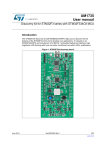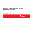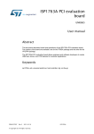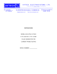
1
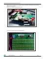
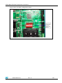
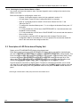
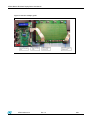
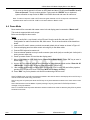
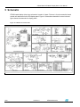
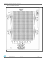
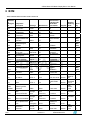
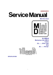
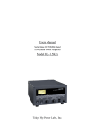
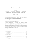
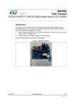
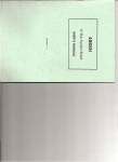
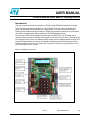
USER MANUAL
STM32 Based LED Matrix Display Demo
Introduction
This user manual describes the operation of STM32 based LED Matrix Display Demo board.
This board demonstrates the capability of STP16DP05 LED driver to drive the matrix LED
panel. The complete system includes one master board, one slave board and LED Matrix
Display panels. Master and slave boards are STM32 microcontroller based control units which
are used for configuring the display settings for STP16DP05 display driver.
This unit has a GPS module interfaced to it through an USART port. The GPS data can be
displayed with information of latitude and longitude and also the real time clock. The display can
be configured for any of the nine different display modes and nine different speeds using a PS2
keyboard. Display panels can also be configured through the HyperTerminal using the serial
interface present on control units. System also consists of audio out for playing back the .wav
file pre recorded in micro sd card.
Figure 1 LED Matrix Control Unit
Rev 1.0
STMicroelectronics
1/26
STM32 Based LED Matrix Display Demo- User Manual
Figure 2.LED Display Panel
DRAFT
2/26
Version1.0
STMicroelectronics
STM32 Based LED Matrix Display Demo-User Manual
Table of Contents
1
2
3
4
Getting Started............................................................................................................................ 4
1.1
Package Contents................................................................................................................4
1.2
Hardware Description...........................................................................................................4
1.3
Power Supply Unit................................................................................................................4
Description Of System ............................................................................................................... 6
2.1
Description of Microcontroller based Control Unit ................................................................6
2.1.1
Address Configuration Of Control Unit .................................................................................6
2.1.2
Selecting the Control Unit as Master or Slave ......................................................................8
2.2
Description of LED Driver based Display Unit ......................................................................8
Configuration of System .......................................................................................................... 10
3.1
One Control Unit and One Display Unit Configuration........................................................10
3.2
Two Control Units and One Display Unit Configuration ......................................................11
3.3
Multiple Control and Display Unit Configuration .................................................................12
Modes Of System Operation.................................................................................................... 14
4.1
PC-UART Communication Mode .......................................................................................14
4.2
GPS Communication Mode................................................................................................16
4.3
Key Board Typing Mode.....................................................................................................16
4.4
Demo Mode .......................................................................................................................17
5
Schematic.................................................................................................................................. 19
6
BOM ........................................................................................................................................... 21
7
Revision History ....................................................................................................................... 26
STMicroelectronics
Rev 1.0
3/26
STM32 Based LED Matrix Display Demo-User Manual
1 Getting Started
1.1 Package Contents
STM32 based led matrix display demo package consists of the hardware and supporting document.
¾ Hardware: One demonstration mother board + One LED Matrix Display Panel
¾ Documentation : User Manual for operating the demonstration board.
1.2 Hardware Description
This complete system has one control unit and a display unit.Control Unit is microcontroller based demo
board and display unit is LED MATRIX board.
Major Components on Control Unit are:
¾ STM32F103VBT6, 32-bit Microcontroller
¾ ST485ABDR, RS485 Transceiver
¾ LD1086D2T33TR, Voltage Regulator
¾ ST3232BDR, RS232 Transceiver
¾ TS461CLT, Rail to rail operational amplifier
¾ TDA2822D, post amplifier
¾ STM1001RW6XF, Reset IC
DRAFT
¾ STPS1L30A, Schottky diode
¾ ESDALC6V1W5,ESD protection device
¾ 16 x 2 Alphanumeric LCD
¾ Mini USB connector
¾ External Power Supply Screw type Connector
Major Components on Display Unit are:
¾ STP16DP05MTR, Display Driver
¾ TIP105, Darlington pair
¾ 74VHC24MTR, Buffer
¾ 16 x 32 LED Matrix
1.3 Power Supply Unit
Power supply for control unit is 5Volt – 0.5Amps DC and for each Display board it is 3.5V -5Volt / 3Amps
DC.
Both control unit and display unit are having one screw type connector each for power supply
connection. Figure 3 shows the power supply connection for Control Unit and Figure 4 shows the
power supply connection for display unit. In each display panel there are 2 screw type connectors for
power connection. VCC+5V0 and GND are mentioned on each of these connectors. Power can be be
STMicroelectronics
Rev 1.0
4/26
STM32 Based LED Matrix Display Demo-User Manual
applied to any one of these two connectors to power the LED panel. Each panel is to be powered
externally and individually.
Figure 3. Power Supply Connection On Control Unit
Figure 4. Power Supply Connection for LED Display Panel
STMicroelectronics
Rev 1.0
5/26
STM32 Based LED Matrix Display Demo- User Manual
2 Description Of System
This STM32 based display demo system is having a microcontroller based control unit and a LED driver based
display unit. Control unit is used for configuring the display driver and display unit is used for controlling the LED
display in accordance to the configuration received from control unit.
2.1 Description of Microcontroller based Control Unit
Control unit is STM32 microcontroller based board. This board has interfaces for :
¾ PS2 keyboard
¾ DB9 (Female) connector for PC serial port (UART) connection
¾ DB9(Male) connector for serial (UART) connection to GPS module
¾ Onboard Numeric Keypad
¾ Audio Jack and also 2 pin connector for external speaker
¾ Screw type connector for RS485 communication between master and slave control units.
¾ 10 x 2 header (Ext.Con) for flat ribbon cable connection to display unit.
¾ Slot for micro SD card
¾ Screw type connector for 5V DC power connection
This microcontroller based unit is used to control the display board. This unit can be configured to
operate as master (responsible for sending the commands for dipaly control) or as slave unit (
responsible for receiving the commands and executing it on display unit). In every system one control
unit acts as a master.
2.1.1
DRAFT
Address Configuration Of Control Unit
Each control unit is having 8 dip switches (SW2). These switches are used to configure the address for
the control unit.
Address configuration for control unit is done by moving the switches either to high or to low positions.
Eight I/O lines are used for address allocation to the control unit. Thus upto 255 addresses can be
assigned to any control board. Board can have any address between 0 and 255.
If switch is slided towards the side where numbers are written then logic ‘1’ is assigned to the port and if
the switch is slided towards the side where “ON” is written then logic ‘0’ is assigned to the board.
Whenever the board is powered up and is connected as slave unit then its address will be displayed on
the LCD mounted on board. Figure 5 shows on board switches.
Note: Address 255 is hardcoded to master unit and no slave unit is allowed to have this address. Thus one should
never slide all the 8 switches to the side where numbers are written(opposite to side where “ON” is written)
6/26
Version1.0
STMicroelectronics
STM32 Based LED Matrix Display Demo-User Manual
Figure 5. Slave Unit Address Configuration Switches
STMicroelectronics
Rev 1.0
7/26
STM32 Based LED Matrix Display Demo- User Manual
2.1.2
Selecting the Control Unit as Master or Slave
Any control unit can act as master or slave. On-board keypad is used to configure the control unit as
Master or as Slave.
Below are the steps for configuring the control unit:
-
Connect 5 volt power supply to control unit (as explained in section 1.3)
-
LCD will display “Press # to enter Configuration Mod” for 4 seconds
-
Press “#” on keypad present on board. LCD will show “Master Sel: Entr*1” and
“Slave Sel: Entr *2”
-
To configure the board as Master press “*1” or to configure the board as Slave press “*2”
on keypad
-
If “*1” was pressed then LCD will show “MASTER BOARD” for 2 seconds and then start
the Master routine on board
-
If “*2” was pressed then LCD will show “SLAVE BOARD” for 2 seconds and then start the
Slave routine on board.
-
On next power up of board LCD will again show the message “Press # to enter
Configuration Mod” for 4 seconds but if “#” is not pressed in 4 seconds then board will
enter in the mode which was configured last time.
2.2 Description of LED Driver based Display Unit
Display unit is STP16DP05MTR LED display driver based panel.
Each display panel is having four STP16DP05MTR LED display drivers, two buffers, eight darlington
pair and a matrix of16 x32 LED’s. Each pannel can be connected in series to make a larger display. This
series connection between the display panels is through 10 x 2 header. 20 pin flat ribbon cable is used
to connect two display panels.Input to display panel is coming from control unit through 20 pin Flat
ribbon cable. Thus first display panel is connected to control unit to receive the data and also to next
display panel to cascade the data further. Total 8 such pannels can be cascaded in series.
DRAFT
Figure 6 shows the connection of Display panel. First panel is connected at both side, one to control
unit using 20 pin cable between Ext Con header on control unit and INPUT header at display panel and
other side to second display panel using OUTPUT header at first panel and INPUT header at second
panel.
Note:Length of the flat ribbon cable (FRC) should not be exceeded 30 cm.
8/26
Version1.0
STMicroelectronics
STM32 Based LED Matrix Display Demo-User Manual
Figure 6.Connection of Display panels
STMicroelectronics
Rev 1.0
9/26
STM32 Based LED Matrix Display Demo- User Manual
3 Configuration of System
Whole system can be connected in one of the following configurations:
1. One control Unit and one display unit without a slave unit
2. Two control units (one acting as a master and other as slave) and one display unit
3. Multiple control units (one acting as a master and rest other as slaves) and multiple display units
(each display unit connected to each slave. One display unit can have up to 8 cascaded panels that
could be controlled by a single slave unit.)
3.1 One Control Unit and One Display Unit Configuration
In this configuration there is single control unit and a single display unit. Control unit will act as master.
Below are the steps to operate the system in this configuration:
Step 1: Connect PS2 keyboard to the control unit
Step 2: Connect the control unit with display panel using 20 pin flat ribbon cable. Insert the cable in
10 x 2 header (Ext.Con) present on master at one side and in header J1 (INPUT) on display panel at
other side.
If needed display panels can be cascaded in series to make a longer display. To cascade display panels
connect 20 pin flat ribbon cable from jumper J3 (OUTPUT) of first panel to jumper J1 (INPUT) of second
panel. Figure 6 shows connections for cascading of display panels. Similarly connect frc cable from
jumper J3 (OUTPUT) of second panel to jumper J1 (INPUT) of third panel and so on to make a longer
display. Up to 8 such display panels can be cascaded in series.
DRAFT
Step 3: Connect the power to master control unit and to display panel as explained in section1.3
Step 4: LCD on master control unit will show ““Press # to enter Configuration Mod” for 4 seconds
Step 5: Press “#” on keypad present on board.If 4 seconds has elapsed and the board was not
configured then it will enter in the mode which was last configured. To again configure it press reset
button.
Step 6: If “#” was pressed then LCD will show “Master Sel: Entr*1” and “Slave Sel: Entr *2”
Step 7: Press “*1” on keypad. LCD will show “MASTER BOARD”
Step 8: After 2 Seconds LCD will start the demo showing “Led Matrix Demo”
Step 9: Display will start showing 4 options:
1) “Press F1 For PC – UART Comm”
2) “Press F2 For GPS Data Display”
3) “Press F3 For Typing Data”
4) “Press F6 For Demo Mode”
Step 10: Press F1 or F2 or F3 or F6 on keyboard to select one of the above mentioned modes.
Step 11: Based on which of the above mentioned key is pressed, system will enter in one of the above
mentioned modes. Operation in each mode is explained in section 4
Step 12: Press ESC on keyboard to exit from the selected mode.
Step 13: Once exited from the selected mode, system will resume from step 9
10/26
Version1.0
STMicroelectronics
STM32 Based LED Matrix Display Demo-User Manual
3.2 Two Control Units and One Display Unit Configuration
In this configuration there are two control units and a single display unit. One Control unit should be
master and other one should be slave. By default system comes with one master and one display panel.
Below are the steps to operate the system in this configuration:
Step 1: Configure one control unit as Master and other control unit as Slave as explained in section 2.1.2
Step 2: Configure the address of Slave board using the onboard DIP switches as explained in
section 2.1.1
Step 3: Connect PS2 keyboard to the master control unit
Step 4: Connect display panel to Slave control unit using 20 pin flat ribbon cable. Insert the cable in
10 x 2 header (Ext.Con) present on slave at one side and in header J1 (INPUT) on display panel at other
side.
If needed display panels can be cascaded in series to make a longer display. To cascade display panels
connect 20 pin flat ribbon cable from jumper J3 (OUTPUT) of first panel to jumper J1 (INPUT) of second
panel. Figure 6 shows connections for cascading of display panels. Similarly connect frc cable from
jumper J3 (OUTPUT) of second panel to jumper J1 (INPUT) of third panel and so on to make a longer
display. Up to 8 such display panels can be cascaded in series.
Step 5: Connect Master and Slave control unit using twisted pair cable. Ensure that RS485+ at master is connected to
RS485+ at slave and RS485- at master is connected to RS485- at slave. Connections are made at screw type connector
(J18).
Figure 7 shows the RS485 connection
Step 6.Power up master control unit, slave control unit and Display panel using DC power supplies
Step 7: LCD on master and slave control unit will show “Press # to enter ConfigurationMod”. If master and
slave boards are already configured (in step 1) then don’t press “#” and boards will resume its functionality
in 4 seconds.
Step 8: Master control unit will start the demo showing “Led Matrix Demo” and slave control unit will start
showing its own address.(Address is configured using on board switches).
Step 9: Display at master will start showing 4 options:
1) “Press F1 For PC – UART Comm”
2) “Press F2 For GPS Data Display”
3) “Press F3 For Typing Data”
4) “Press F6 For Demo Mode”
Step 10: Press F1 or F2 or F3 or F6 on keyboard (attached to master board) to select one of the above
mentioned modes.
Step 11: Based on which of the above mentioned key is pressed, system will enter in one of the above
mentioned modes. Operation in each mode is explained in section 4.
Step 12: Master control unit will send commands to slave control unit. Slave control unit will process
these commands and configure the display panel for displaying entered data
Step 13: Press “ESC” on keyboard attached to master board to exit from present mode. After this system
will resume from Step 9.If new address entered( for slave selection) matches with the slave address then
slave display will be interrupted else display will continue will old data display.
STMicroelectronics
Rev 1.0
11/26
STM32 Based LED Matrix Display Demo- User Manual
Figure 7. RS485 Communication
DRAFT
3.3 Multiple Control and Display Unit Configuration
In this configuration there are multiple control units and multiple display panels. One Control unit should be
master and rests other are slave. By default system comes with one master and one display panel.
Below are the steps to operate the system in this configuration:
Step 1: Configure one control unit as Master and other control units as Slave as explained in section 2.1.2
Step 2: Configure the address of Slave boards using the onboard DIP switches as explained in
section 2.1.1
Step 3: Connect PS2 keyboard to the master control unit
Step 4: Connect display panels to each Slave control unit using 20 pin flat ribbon cable. Insert the cable in
10 x 2 header (Ext.Con) present on slave at one side and in header J1 (INPUT) on display panel at other
side.
If needed display panels can be cascaded in series to make a longer display. To cascade display panels
connect 20 pin flat ribbon cable from jumper J3 (OUTPUT) of first panel to jumper J1 (INPUT) of second
panel. Figure 6 shows connections for cascading of display panels. Similarly connect frc cable from
jumper J3 (OUTPUT) of second panel to jumper J1 (INPUT) of third panel and so on to make a longer
display. Up to 8 such display panels can be cascaded in series.
Step 5: Connect Master and Slave control units using twisted pair cable. Ensure that RS485+ at master is
connected to RS485+ at slave and RS485- at master is connected to RS485- at slave. Connections are
made at screw type connector (J18). Figure 8 shows the RS485 connection topology.
12/26
Version1.0
STMicroelectronics
STM32 Based LED Matrix Display Demo-User Manual
Step 6.Power up master control unit, slave control units and Display panels using DC power supplies.
Please ensure in the case of cascading of display panels, power should be individually supplied at J5
screw type connector on each display panel.
Step 7: LCD on master and slave units will show “Press # to enter ConfigurationMod”. This will be
displayed for 4 seconds. If master and slave boards are configured in Step 1 then don’t press “#” and
boards will resume the functionality in 4 seconds
Step 8: Master control unit will start the demo showing “Led Matrix Demo” and slave control unit will start
showing its own address.(Address is configured using on board switches).
Step 9: Display at master will start showing 4 options:
1) “Press F1 For PC – UART Comm”
2) “Press F2 For GPS Data Display”
3) “Press F3 For Typing Data”
4) “Press F6 For Demo Mode”
Step 10: Press F1 or F2 or F3 or F6 on keyboard to select one of the above mentioned modes.
Step 11: Based on which of the above mentioned key is pressed, system will enter in one of the above
mentioned modes. Operation in each mode is explained in section 4.
Step 12: Master board LCD will ask for address of slave control unit in order to configure the display unit
If the address entered at master unit matches with the slave unit then the selected slave unit can be
configured for display else “Address Mismatch” is displayed over LCD and new address entry is
requested.
Step 13: When address is matched then Master control unit will send commands to selected slave control
unit. Slave control unit will process these commands and configure the display panel for displaying
entered data. Rest other slave units will continue to display old data.
Step 14: Press “ESC” to exit from present mode. After this system will resume from Step 9.If new address
entered( for slave selection) matches with the slave address then slave display will be interrupted else
display will continue with old data.
Figure 8. RS485 Multi Drop Topology
Slave
RS485+ RS485-
RS485+
Master
RS485+
R
Slave
R
RS485-
RS485-
RS485+
RS485-
RS485+
Slave
STMicroelectronics
RS485-
Slave
Rev 1.0
13/26
STM32 Based LED Matrix Display Demo- User Manual
Note: R is the termination resistance used for impedance matching
DRAFT
14/26
Version1.0
STMicroelectronics
STM32 Based LED Matrix Display Demo-User Manual
4 Modes Of System Operation
LED Display demo board has 4 different modes of operation. These are:
1. PC-UART Communication Mode
2. GPS Module Communication Mode
3. Key Board Typing Mode
4. Demo Mode
As soon as master control unit is powered up, LCD on master board will show “MASTER BOARD” for
first 2 seconds and then a menu will be started which ask for pressing F1/F2/F3/F6 for selecting one of
the above mentioned modes.
4.1 PC-UART Communication Mode
Master control unit communicates with computer using UART communication protocol. Female DB9
connector on control unit is used to connect to a computer using serial connection cable.
Below are the steps to communicate using HyperTerminal of computer:
Steps:
1. Connect a serial cable between serial port of computer and female DB9 connector of master control
unit (VB1)
2. Connect PS2 keyboard to master control unit.
3. Configure HyperTerminal on computer using following settings:
Bits per Second: 115200
DataBits: 8
Parity: None
Stop bits: 1
Flow Control: None
4. Make the ASCII settings as shown in
Figure 9.
5. Power up master control unit, LED Panel and also slave control unit (if connected)
6. LCD on master will show the menu program asking for “Press F1 for PC-USART Comm”
7. Press “F1” key on the keyboard attached to PS2 connector of master control unit
8. HyperTerminal will show a message
-“USART HyperTerminal Communication Demo Maximum Allowed String Length is 200
Words”.
- “Enter Display Board Address, Enter 1-255”
9. Enter the slave control unit address (as seen on LCD of slave control unit) or address of
master(255) and then press “Enter” key on PC keyboard. Addresses allowed are between 1 and
255.
10. If the entered address is not present then there will be an error message on Hyper terminal
“Address Mismatch; Enter Display Board Address”. Check the address of slave board and then
re enter on hyper terminal.
11. When address is matched then Message on hyper terminal is “Enter No. Of LED Boards”. Enter
number of LED display panels connected in cascade to the selected control unit.
12. Next message will be “Enter Mode; Entr between 1-9”. This is for entering one of 9 display modes.
These modes are as followings:
STMicroelectronics
Rev 1.0
15/26
STM32 Based LED Matrix Display Demo- User Manual
a. Mode 1 => Curtain Up
b. Mode 2 => Curtain Down
c. Mode 3 = > Left To Right Scroll
d. Mode 4 => Right To Left Scroll
e. Mode 5 => Typing Data mode
f. Mode 6 => Stable Display
g. Mode 7 => Flashing mode
h. Mode 8 => Curtain Right
i. Mode 9 => Curtain Left
If the mode entered is other than 1-9 then default mode will be selected and message will be seen
on terminal: “Default Mode : Right To Left”
13. As soon as mode is entered, selected mode will be seen on hyper terminal and then the next
message will be “Enter Speed; Entr between 1-9”. This speed is for seeing the display on LED
Matrix. Speed 1 is fastest and 9 is slowest. If speed entered is other than 1-9 then default speed of 2
will be selected
14. Next message will be “Enter String”
15. Enter the string (maximum allowed string length is of 200 letters).When required string is entered, hit
ENTER key on keyboard.
16. Data will be sent to LED Matrix display and can be seen over there.
17. Next message on hyper terminal will be “Enter Y to Re-enter Display Mode Settings or any other
key to Exit PC-UART mode:” Thus if Y is entered then system will start from step 8. If any other
key is entered then system will exit from PC-UART mode and normal menu will be seen on LCD of
master control unit.
DRAFT
Figure 9. ASCII settings of Hyper terminal in Computer
16/26
Version1.0
STMicroelectronics
STM32 Based LED Matrix Display Demo-User Manual
4.2 GPS Communication Mode
Global Positioning System mode is used for interacting with externally connected GPS module and
display Time, Latitude, Longitude and Satellite fixture status.
Below are the steps for communicating with GPS module:
Steps:
1. Connect a serial cable between GPS module and DB9 male connector (VB2) of master control unit.
GPS systems should follow the handshaking protocol for serial communication.
2. Connect PS2 keyboard to master control unit.
3. Power up master control unit, LED Panel and also slave control unit (if connected)
4. LCD on master will show the menu program asking for “Press F2 for GPS Data Display ”
5. Press “F2” key on the keyboard attached to PS2 connector of master control unit
6. LCD at master will show GPS mode selected and “Enter Display Board Address”. Enter the slave
board address where data is to be displayed on LED Matrix panel. Addresses allowed are in
between 1 and 255. 255 is fixed for master unit. If wrong data is entered then LCD will show
“Address Mismatch” and will again ask for address
7. When address is matched then LCD will ask for entering the number of display panels connected in
cascade at selected slave device.
8. As soon as number of display panels is entered, LED Matrix will start showing Time, Latitude,
Longitude and Satellite fixture status on LED Matrix.
9. Press “ESC” on keyboard to exit from GPS mode and return to main menu.
4.3 Key Board Typing Mode
This mode is for user interaction using the key board attached at PS2 connector mother board.
Below are the steps for operating in Typing mode:
Steps:
1. Connect Key Board to PS2 connector on master control unit.
2. Power up master control unit ,LED Panel and slave control unit (if present)
3. LCD on master will show the menu program asking for “Press F3 for Typing Data ”
4. Press “F3” key on the keyboard attached to PS2 connector of master control unit
5. LCD at master will show “Enter Display Board Address”. Enter the slave board address where
data is to be displayed on LED Matrix panel. Addresses allowed are between 1 and 255.255 is
fixed for master unit. If wrong data is entered then LCD will show “Address Mismatch” and will
again ask for address
6. When Address is matched, LCD will show message “Enter No. Of LED Boards”. Enter number
of LED panels connected in cascade to the selected control unit
7. Next message will be “Enter Mode; Entr between 1-9”. This is for entering one of 9 display
modes. Modes are explained in step 12 of section 4.1
8. As soon as mode is entered, selected mode will be seen on LCD and then will ask for “Enter
Speed; Entr between 1-9”. This speed is for seeing the display on LED Matrix. Speed 1 is fastest
and 9 is slowest. If speed entered is other than 1-9 then default speed of 2 will be selected
9. Next message will be “Enter String ; Pres ESC to exit”
10. Enter the data which is to be seen on LED Matrix display. If user does not want to enter data and
wants to exit from this mode, then “ESC” key should be pressed
STMicroelectronics
Rev 1.0
17/26
STM32 Based LED Matrix Display Demo- User Manual
11. As soon as data is entered, it will seen on LED Matrix and then LCD will show”Pres ESC to exit;
Enter to Proceed”. Thus to continue with the Typing mode hit “ENTER” key on keyboard,
system will switch to step 5 else hit “ESC” to exit from this mode and return to main menu.
Note: To check is Caps lock is ON or OFF see to the typed character on LCD. If Caps lock is ON then the
alphabets will be seen in CAPITAL CASE on LCD else it will be in SMALL CASE.
4.4 Demo Mode
Demo mode will be executed with master control unit and display panel connected to “Master unit”.
This mode is supported with audio output.
Below are the steps for demo mode:
Steps:
1. Save an audio file in .wav format in micro SD card. Save the audio file with name “STN2”.
Configuration for audio file should be: 8Bit, 8kHz mono. This is the audio which will be heard from
board.
2. Insert micro SD card in memory card slot connected at back side of master as shown in Figure 10.
3. Connect a display panel to master control unit using 20 pin flat ribbon cable.
4. Connect PS2 keyboard to master unit
5. Connect external speaker to two pin audio connector (near audio jack) or to audio jack. Audio jack is
having a mono output only.
6. Power up master control unit and also the display panel.
7. Menu will be started on LCD. It will display “Press F6 for Demo Mode”. Press “F6” key to enter in
Demo mode.
DRAFT
8. As soon as F6 is pressed, LCD will show message for entry of display panel number “Enter No. Of
LED Boards”. Enter number of display panel connected to master unit.
9.
After number of led panels is entered audio file saved as STN2 in micro SD card will be played on
speaker and LED panel will show a message”Wish You A Happy Journey”.
10. Press “ESC” key on key board to exit from this mode and go back to menu.
Note:For DEMO mode, microSD card should be insetred in the card slot else no data display will occur.ESC key is
used to exit from this mode at any point of time.
Note: At any point of system press twice the ESC key on key board attached to master unit to return back to main
menu.
Note: Untill we enter one of the Modes of system pressing of any key (other than F1/F2/F3/F6) will show a
message of “Key Not Allowed”.
Note: In PC USART mode key board attached to mother unit will not be active for data entry.Only ESC key will be
functional in this mode.
18/26
Version1.0
STMicroelectronics
STM32 Based LED Matrix Display Demo-User Manual
Figure 10. Micro SD card Connection
STMicroelectronics
Rev 1.0
19/26
STM32 Based LED Matrix Display Demo- User Manual
5 Schematic
STM32 based display driver demo schematic is made in 2 parts. First one is for microcontroller based
control unit and second is for LED display panel. Figure 11 shows the schematic for control unit and
figure shows the schematic for display panel.
Figure 11 Schematic for Control Unit
DRAFT
20/26
Version1.0
STMicroelectronics
STM32 Based LED Matrix Display Demo-User Manual
Figure 12 . LED Display Panel Schematic
STMicroelectronics
Rev 1.0
21/26
STM32 Based LED Matrix Display Demo- User Manual
6 BOM
Table 1.BOM Of Microcontroller based Control Unit
SO8
ST
U4
ST485ABDR
L9615D/CAN
Transceiver
Manufacturer’s
ordering code
/ Orderable
Part Number
STM32F103VB
T6
ST485A
BDR
SO8
ST
L9615D
U5
M25P128VMF6TP/S
erialFlash
SO16
ST
M25P128VMF6
TP
ST
SPZB260
1
Not
Mou
nted
Not
Mou
nted
SO8
ST
TDA2822D
1
SOT23-5L
ST
1
DPAK
ST
TS461CLT
LD1086DT33T
R
SO 16
ST
SOT23-3
SOT-666
ST
ST
ST3232CDR
STM1001RWX
6F
USBLC6-2P6
SO8
ST
M24M01HWMN6TP
SMA
ST
STPS1L30A
Referenc
e
Designat
or
U2
U3
U6
U7
U8
U9
U10,U11
U12
U13
U14
Z1
Component
Description
STM32F103VBT6/Mi
crocontroller
SPZB260/Zigbee
Moudule
TDA2822D/Post
Amplifier
TS461CLT/Rail to
rail op amp
LD1086DT33TR/Volt
age Regulator
ST3232CDR/RS323
2 Driver Receiver
STM1001RWX6F/Re
set Ic
USBLC6-2P6
M24M01HWMN6TP/EEPRO
M
STPS1L30A/Schottk
y Rectifier
Package
Manufacturer
LQFP
ST
Supplier
1
1
XTAL-3
ECS
ECS-327-18-9X
Mouser
Y2
8Mhz
XTAL-3
Fox
FOXSLF/08020
Mouser
USB
CONN1
USB-B Type Mini
Connector
SMD
Molex
67503-1020
Mouser
VB1
DB9
Connector/Female
through
hole
Tyco
Electronics
5747844-4
Mouser
through
hole
Tyco
Electronics
5747840-4
Mouser
16 x
1Bergstrip
Oriole
ODM162169SL3/AX
Oriole
J2
22/26
LED Board
connector
10 x 2
header
Molex
Version1.0
70246-1001
1
1
Not
Mou
nted
1
32.768kHz
J1
2
DRAFT
DB9 Connector/Male
LCD Connector and
16 x 2 alphanumeric
LCD
Quan
tity
1
Y1
VB2
Supplier
Ordering
Code
Mouser
STMicroelectronics
520-ECS3276-189X
559FOXS080
-20-LF
538675031020
57157478444
57157478404
1
1
1
1
1
1
538702461001
1
STM32 Based LED Matrix Display Demo-User Manual
J5,J14,J1
5
3 PIN Berg Strip
3x1
Bergstrip
Any
Samtec
TSW-15032-G-S
J6
7 PIN Berg Strip and
Keypad
7 x1 pin
Bergstrip
Any
Futurlec
KEYPAD3
X4B
J8
8 pin header/zigbee
header
8 pin
header
3 pin
through
hole
J9
Audio Jack
J10
Jtag Connector
J12,J16
Berg Strip/Jumers
J18
screw type connector
CONN1
MMC card connector
10 x 2
header
5x
1Bergstrip
through
hole
J17
screw type connector
smd
through
hole
D1,D3
LED-Red
LED-3mm
C1,C2
4.7nF
SMD0805
C3,C4,
10pF
SMD0805
Any
CUI
SJ1-3523NG
Digikey
Molex
70246-1001
Mouser
Any
Phoneix
Contact
Proconn
Technology
Phoneix
Contact
Samtec
1729131
MSPN09-X01000
Everlight
Panasonic ECG
Panasonic ECG
EL-204HT
ECJ2VB1H472K
ECJ2VC1H100D
GQM2195C1H2
00JB01D
ECJ2VB1H103K
Digikey
Digikey
1729128
C5,C6
20pF
SMD0805
C7,C30
C8,C9,C
10,C15,C
16,C17,C
18,C19,C
20,C21,C
22,C28,C
33,C34,C
35,C40,C
41,C42,C
46,C47,C
48,C49,C
50,C51,
C52,C53,
C54,C55
10nF
SMD0805
Murata
Electronics
North America
Panasonic ECG
SMD0805
Panasonic ECG
ECJ2VB1E104K or
equivalent
Vishay/Spragu
e
Panasonic ECG
Panasonic ECG
293D106X96R3
A2TE3 or
equivalent
ECJ2VB1H333K
ECJ2VC1H470J
100nF
C23,C24,
C25,C26,
C44,C45
C27,C29,
C31
10uF
Case A
33nF
SMD0805
C32
47pF
SMD0805
STMicroelectronics
Rev 1.0
Mouser
CP13523NGND
538702461001
TSW-15032-G-S
6511729131
3
1
Not
Mou
nted
1
1
1
1
1
Mouser
Mouser
Digikey
Digikey
Digikey
Mouser
Digikey
Digikey
6511729128
638204HT
PCC472B
NTR-ND
PCC100C
NTR-ND
490-36072-ND
PCC103B
NTR-ND
PCC1828
CT-ND
74293D106
X96R3A2
TE3
PCC1834
TR-ND
PCC470C
GTR-ND
1
2
2
2
2
2
28
6
3
1
23/26
STM32 Based LED Matrix Display Demo- User Manual
SMD0805
Panasonic ECG
Panasonic ECG
Panasonic ECG
TDK
Corporation
Panasonic ECG
ECJ2YF1A475Z
ECJ2FB1A335K
ECJ2VC1H181J
FK22X5R0J107
M
ECJ2VC1H150J
988k
SMD0805
Stackpole
Electronics Inc
RNC 20 T2
988K 0.1% R
R2
3k5
SMD0805
R4,R5
22
SMD0805
R6,R16
1M
SMD0805
R7
R8,R41,
R46
R10,R70,
R71
R11,R12,
R13,R14,
R17,R20,
R27,R30,
R38,R39,
R40,R48,
R49,R50,
R51,R53,
R60,R61,
R62,R68,
R69
100
SMD0805
0
SMD0805
4k7
SMD0805
Stackpole
Electronics Inc
Panasonic ECG
Panasonic ECG
Panasonic ECG
Panasonic ECG
Panasonic ECG
RNC 20 T9
3.52K 0.1% R
ERJ6GEYJ220V
ERJ6GEYJ105V
ERJ6GEYJ101V
ERJ6GEY0R00V
ERJ6GEYJ472V
SMD0805
Panasonic ECG
ERJ6GEYJ103V
C36
4.7uF
SMD0805
C38
3.3uF
SMD0805
C39
180pF
C43
100uF
SMD0805
through
hole
C56,C57
R1,R3,R
9,R18,R1
9,R21,R2
3,R42,
R45
15pF
Digikey
Digikey
Digikey
Digikey
10k
R24
SIP9
R15,R57
470
SMD0805
R22,R31
R25,R29,
R64,R65
1k
SMD0805
499
SMD0805
R26,R63
120
SMD0805
R28
1.5k
SMD0805
R32,R36
510
SMD0805
BI
Technologies
Panasonic ECG
Panasonic ECG
Panasonic ECG
Panasonic ECG
Panasonic ECG
Panasonic ECG
Version1.0
L091C103LF
ERJ6GEYJ471V
ERJ6GEYJ102V
ERJ6ENF4990V
ERJ6GEYJ121V
ERJ6GEYJ152V
ERJ6GEYJ511V
PCC1842
TR-ND
PCC2288
TR-ND
PCC181C
GTR-ND
445-2902ND
PCC150C
NTR-ND
digikey
RNC20T2
988KBRND
RNC20T9
3.52KBRND
P22ATRND
P1.0MAT
R-ND
P100ATR
-ND
P0.0ATRND
P4.7KAT
R-ND
digikey
P10KACT
-ND
digikey
digikey
digikey
digikey
digikey
digikey
DRAFT
10k/ Resistor bank(9
PIN)
24/26
Digikey
Mouser
digikey
digikey
digikey
digikey
digikey
digikey
STMicroelectronics
858L091C103
LF
P470ATR
-ND
P1.0KAT
R-ND
P499CTR
-ND
P120ATR
-ND
P1.5KAT
R-ND
P510ATR
-ND
1
1
1
1
2
9
1
2
2
1
3
3
21
1
2
2
4
2
1
2
STM32 Based LED Matrix Display Demo-User Manual
SMD0805
Panasonic ECG
Panasonic ECG
Panasonic ECG
Panasonic ECG
Panasonic ECG
Panasonic ECG
ERJ6GEYJ222V
ERJ6GEYJ122V
ERJ6GEYJ101V
ERJ6GEYJ183V
ERJ6GEYJ153V
ERJ6GEYJ822V
330E
SMD0805
Panasonic ECG
ERJ6GEYJ331V
R66
DO NOT MOUNT
SMD0805
Any
SW1
Push Button RESET
switch
JS1
DIP 8 switch
Mini Din/key board
connector
through
hole
through
hole
through
hole
F1
1 amp Fuse
connector + Fuse
BT1
Coin Battery
connector
R33
2.2k
SMD0805
R34,R35
1.2k
SMD0805
R37
100
SMD0805
R43
18k
SMD0805
R44
15k
SMD0805
R47
82k
R52
R54,R55,
R56,R58,
R59,R67
DO NOT MOUNT
SW2
STMicroelectronics
digikey
P2.2KAT
R-ND
P1.2KAT
R-ND
P100ATR
-ND
P18KATR
-ND
P15KATR
-ND
P8.2KAT
R-ND
digikey
P330ATR
-ND
1
digikey
digikey
digikey
digikey
digikey
1
2
1
1
1
1
Not
Mou
nted
1
Not
Mou
nted
E-Switch
C&K
Components
TL1105F250Q
Mouser
612TL1105250
BD08
Mouser
611-BD08
1
Kobiconn
161-2306
Mouser
1
through
hole
Keystone
Electronics
0217.500HXP +
4527C
Mouser
161-2306
5760217.500
HXP +
5344527C
through
hole
Any
Rev 1.0
1
Not
Mou
nted
25/26
STM32 Based LED Matrix Display Demo- User Manual
Table 2. BOM of LED Display Panel
Reference
Designator
U1,U2,U5,U6
U3,U4
Q1,Q2,Q3,Q4
,Q5,Q6,Q7,Q
8
Component
Description
Package
Manufacturer
Manufacturer’s
ordering code /
Orderable Part
Number
STP16DP05MT
R/Display driver
74VHC245MTR
SO24
SOP20
ST
ST
STP16DP05MT
R
74VHC245MTR
TO-220
ST
SOT323-5L
ST
P1,P2,P3,P4
TIP127
ESDALC6V1W
5/Quad transil
J1,J3
10 X 2
HEADER
J5,J6
2 pin Molex
Connector
10 X 2 BOX
HEADER
2 PIN
Through
hole
D1 to D512
PLC
SMD
C1,C2,C3,C4,
C6,C7
C5,C10
C8,C11,C12,
C13
R1,R2,R19,R
20
R3,R4,R5,R6,
R7,R8,R9,R1
0,R11,R12,R1
3,R14,R15,R1
6,R17,R18
26/26
Supplier
10uF
Quantity
4
2
TIP127
ESDLALC6V1W
5
8
4
Molex
70246-1001
Mouser
Phoenix
Contact
1729128
Mouser
LS T676R1S1-1-Z
Osram
Digikey
SMD0805
Panasonic ECG
ECJ2VB1E104K or
equivalent
Digikey
Case A
Vishay/Spragu
e
293D106X96R3
A2TE3 or
equivalent
538702461001
6511729128
4752683-1ND
2
2
512
Mouser
PCC182
8CT-ND
74293D106
X96R3A2
TE3
2
4
DRAFT
100nF
Supplier
Ordering
Code
6
220uF
SMD0805
Nichicon
UKW1E221MPD
Mouser
647UKW1E2
21MPD
1k
SMD0805
Xicon
292-1.0K-RC or
equivalent
Mouser
2921.0K-RC
4
4k7
SMD0805
Xicon
292-4.7K-RC or
equivalent
Mouser
2924.7K-RC
16
Version1.0
STMicroelectronics
STM32 Based LED Matrix Display Demo-User Manual
7 Revision History
Revision
1.0
Date of modification
December 2, 2008
STMicroelectronics
Description of modification
Initial draft
Rev 1.0
27/26