1
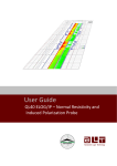
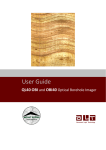
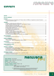
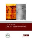
40GRP-1000 Combination Gamma - Normal Resistivity Probe Mount Sopris Instrument Company, Inc. Advanced Logic Technology s.à, Mount Sopris Instrument Company, Inc. 4975 E. 41st Ave. Denver CO 80216 USA Advanced Logic Technology s.à, Zoning de Solupla, Bâtiment A, route de Niederpallen, L-8506 Redange sur Attert, Grand Duchy of Luxembourg. April 22, 2013 Table of Contents General Information .....................................................................................................................3 40 Series Probe Overview ......................................................................................................3 Minimum requirements: ..........................................................................................................3 Connections, and Layout ........................................................................................................3 Probe Top sub connections: ...........................................................................................3 40GRP-1000 ...........................................................................................................................4 40GRP-1000 Specifications: ........................................................................................................4 Power Requirements ..............................................................................................................4 Electrode details .....................................................................................................................4 Electrode reference measuring point (from bottom of bronze knurled ring) ...........................4 Operating temperature range .................................................................................................4 Measurement Specifications ...................................................................................................5 Principal of Operation-40GRP-1000 ............................................................................................6 Setting up the 40GRP-1000 and support equipment ..............................................................6 Operating Procedure ....................................................................................................................8 Operation ................................................................................................................................8 40GRP Browsers ....................................................................................................................9 Performance Checks and Calibrations ...................................................................................11 Preventative Maintenance ......................................................................................................12 Locking Ring assembly Maintenance .............................................................................12 Troubleshooting ...........................................................................................................................13 Problems with the Tool ...........................................................................................................13 Disassembly Instructions ........................................................................................................13 Appendix ......................................................................................................................................14 Suggested QA Procedure .......................................................................................................14 General Information 40 Series Probe Overview Each probe in the 40 series has a Telemetry and Power supply element which provides improved communications on long single and four conductor wirelines. The 40GRP-1000 probe is delivered with a QL40 series probe top, which is also used in the QL40 stackable probe line. This probe top allows the 40GRP probe to use the same isolation bridle used with the QL40 series Res, IP, and DLL3 subs. The number 40 indicates a nominal OD of 40mm. Over coating and special measurements may make some subs larger in diameter than this. See their particular specifications. Minimum requirements: Matrix v10.XX software with appropriate Matrix Logger firmware See the installation instructions for Matrix software for more information. Connections, and Layout Connections for the tool are as follows. The 40GRPprobe must use the Q40series isolation bridle as its’ connection to the wireline cablehead. This is needed to allow the 64” normal resistivity measurement to have the required isolation for its voltage measurement. Failure to use an isolation bridle will result in poor data quality and incorrect resistivity values.. The probe injection current injection electrode (“A”) returns to cable armor (“B”). Armor must be isolated from the 16 and 64 inch measure electrodes by at least 7 meters (effected by the isolation bridle). This is the primary reason that an isolation bridle is required for a valid measurement. Probe Top sub connections: Q40ISI-single conductor bridle Pin Bridle top housing Center pin in bridle top Isolated bridle electrode Q40IS4-four conductor bridle Pin Bridle top housing 1 2-4 3 Isolated bridle electrode Signal Tool power ground, injection current return Tool power positive Measure Voltage Reference Origin Armor Signal Tool power ground, injection current return Tool power positive No Connection Tool power positive Measure Voltage Reference Origin Armor Center conductor Com A&B No Connection Com C&D P/N 70000235 3 40GRP-1000 The 40GRP probe provides 2 normal resistivity measurements, plus spontaneous potential (SP), single point resistance (SPR), and natural gamma. Isolation from armor is a critical requirement that cannot be overemphasized when running any resistivity probe. Incorrect measurements will result if isolation is not adequate. 40GRP-1000 Specifications: Power Requirements DC voltage at probe top. MIN. 80 VDC MAX. 160 VDC Nominal 120VDC Current 52 mA nominal, 70 mA max Current source electrode in probe outputs 32V pp square wave (+/- 16V) at up to 500 mA Electrode details Current Electrode 50 mm 304 stainless Measure Electrodes 18 mm 304 stainless Electrode reference measuring point (from bottom of bronze knurled ring) SP 1.777 m up from bottom of probe 16” normal 0.3548 m up from bottom of probe 64” normal 0.9644 m up from bottom of probe SPR 0.152 m up from bottom of probe Gamma 0.73 m up from bottom of probe Operating temperature range 32 to 158 degrees F 0 to 70 degrees C Pressure rating 2900 psi 200 bars Dimensions Length Diameter Weight 78 inches 1.63 inches 16 lbs 198 cm (add 29.3 cm for standalone operation) 41.4 mm with neoprene heat shrink and PVC electrical tape 7.3 kg (note that probe plus isolation bridle will weigh a total of 35.8 pounds (16.3 kg) and be effectively 32.36 ft.(9.865 m.) long.) P/N 70000235 4 Measurement Specifications SP Range: +/- 18 V Resolution: 0.5 mV Accuracy: +/- 2.5 mV SPR, 16”” and 64” Normal Resistivities Range: 0.1 to 100,000 ohm-m Resolution: <0.04% of measured value (24 bit/0.5 msec ADC with real-time downhole digital filtering Accuracy: <1% of measured value from 10 to 1000 ohm-m <5% of measured value from 1 to 5000 ohm-m See graph below for accuracy range versus resistivity: Figure 1 P/N 70000235 5 Principal of Operation-40GRP-1000 The QL40-ELOG has 3 electrodes which are used for measuring normal resistivity at 2 spacings, spontaneous potential, and single point resistance. The 40GRP-1000 probe must have an isolation bridle placed above it to provide a remote reference electrode for the normal resistivity channels, and a remote return for the injection current. The SP (spontaneous potential) is measured between the 64” normal measure electrode and armor. The data recorded as SP or VSP measures the natural voltages sensed by this electrode. These voltages can be related to both electrochemical and electrokinetic forces in the borehole. The electrochemical SP is developed when there is a difference between the formation fluid and borehole fluid salinities, and occurs normally when the measure electrode passes a clay or shaly zone, which acts as an ion selective membrane. The resulting current flow in a “cell” comprised of those three elements provides a negative SP if the borehole fluid is less conductive than the formation fluid. In fresh water zones, the SP is often positive. The electrokinetic SP can occur when borehole fluid mechanically invades porous and permeable formation, causing a current flow. The SPR is measured between the ”A” current injection electrode on the bottom of the probe and the isolated cable armor above the bridle. This SPR is a qualitative indication of the electrical resistance of the formation material immediately adjacent to the current electrode. The principal of measurement follows Ohm’s law, where R=V/I. As the current flows toward the armor return, the current density ( I/cross-sectional area) decreases dramatically. This means that the majority of the resistance measured is influenced by the material closest to the current electrode. For this reason, the SPR is very sensitive to small changes in resistance close to the borehole. The two Normal Resistivity measurements are made at the halfway between the “A” current electrode and each of the 2 “M” normal resistivity electrodes. The normal resistivity measurement includes a reference electrode, called “N”, which is assumed to be at electrical infinity compared to the measure electrodes. In this special application of Ohm’s law, V=IR still applies, but is re-written as R=V/I. Where G is called the geometric factor, and is related to the A-M spacing between electrodes. In metric units, G is approximately 12.5 * AM spacing. Note that for normal resistivity measurements, the result is 2 true resistivity, expressed in ohm-m /m. It is important to remember that this application of Ohm’s law assumes that the formation is homogenous and infinite. Corrections for borehole size, borehole/formation fluid ratio, and bed thickness should be applied to get true formation resistivity. See appendix for references. The SPR and normal resistivity measurements are made using a 50 msec long +/-16V square wave downhole current generator, which can supply up to 500 mA of survey current. The polarity of the current is alternated between + and – relative to armor to prevent polarization of the electrodes. Setting up the 40GRP-1000 and support equipment Before operating the 40GRP probe, connect the correct isolation bridle to the cablehead. Connecting the isolation bridle to the cable head is much easier than connecting to the probe first and having to handle the bridle plus probe (a 9 meter long assembly) for this task. Once the isolation bridle is attached, make sure that insulating tape is covering the exposed steel on the top part of the bridel, and the first few inches of the cable head. Remember that an isolation bridle MUST BE USED for proper E-LOG measurements P/N 70000235 6 The QL inter-sub units are connected by threading the male end of the top sub (lower part of isolation bridle, into the mating part on the top of the 40GRP probe Locate the spanner wrenches and isolation bridle: Figure 2 Align the top sub on the isolation bridle with the key way inside the top of the 40GRP housing. Inspect all O-rings for defects and make sure threads are clean. Threads and O-rings should be lightly greased. Slide the isolator lower sub in until the threads meet the mating ones inside the housing. Start turning the brass nut by hand until the threads engage. Warning: Do not force the threads! When properly aligned they should turn smoothly. Use the spanner wrenches to tighten the threads until the brass nut is fully engaged. Do not overtighten the brass threaded ring. It only needs to be “snug”. 40GRP isolation requirements After the bridle and 40GRP probe are connected, it is imperative that any steel or brass surfaces, OTHER THAN THE 3 ELECTRODES, must be completely covered with insulating tape. Failure to do this will result in incorrect resistivity values. DO NOT tape the 50 mm current electrode or either of the two 18 mm measure electrodes. A properly prepared probe will show only those 3 electrodes exposed, with no other conductive surfaces showing. Figure 3, below, shows how the isolation bridle should be connected to the top of the 40GRP probe. Figure 3 P/N 70000235 7 Operating Procedure Operation To use the 40GRP probe with the MATRIX logging system, make sure the correct sub files are installed in the C:\Logger\Tools\QL-Standalone directory. The files are most easily installed using LoggerSettings.exe utility program supplied with the software installation. 40GRP sub files may be found on the installation or separate CD. In the case of the Matrix logger, the power settings are set to default values that are used for all probes equipped with the QL TelePSU downhole power supply. Different wirelines may require some adjustment to the telemetry. These settings are accessed by pressing the Settings button in the Telemetry panel of the Matrix dashboard. The user may also view the pulse stream on the cable line by pressing on the Scope button. Select the correct winch/wireline from the Pull-down menu in the Telemetry Selection Scheme window. To view/change telemetry settings, press the properties button. The Configure ALT Telemetry View displays the current discriminator levels (vertical yellow lines) and a histogram of the up-hole data signal. The scales of the Analysis View can be adjusted using the Vertical Scale and Horizontal Scale knobs and the linear / logarithmic scale buttons. The status of the configuration should be flagged as Valid (indicated by the LED being green). In any other case (LED red) the telemetry should be adjusted (we assume a pulse signal is displayed in the analysis view). Click on the Advanced button to display additional controls to tune the telemetry. The Automatic settings option is the preferred mode and should allow the telemetry to be configured for a wide range of wirelines without operator input. For wirelines with a more limited bandwidth, the operator might need to turn off the automatic mode and adjust the telemetry settings manually. For each wireline configuration, the discriminators (vertical yellow lines) for the positive and negative pulses must be adjusted in order to obtain a valid communication status (see Figure 4 for an example of a suitable discriminator position). There is also the option to alter the baudrate in order to optimize the logging speed. The input gain can be increased (long wirelines) or decreased (short wirelines) in order to set up the discriminator levels correctly. Always adjust the gain manually, and never set it to automatic! Figure 4 P/N 70000235 8 Once the telemetry is correctly set, store the new settings as default. The tool should go through the initialization sequence in “Valid” status the next time the power is turned on. 40GRP Browsers The 40GRP sub file produces two display browsers, which present the log curves (MchCurve) and the log data (MchNum).. The MchCurve data includes normal resistivities, SP, SPR, and gamma. The user can select the curves to be presented by clicking on the EDIT, Show Logs button on the MchCurve menu bar, and remove or add curves: Figure 5 Figure 2 P/N 70000235 9 Similarly, the user can select which numerical data values to display in the MchNum browser using the same method, by clicking on the Edit button after right clicking on that browser, and then going to the Display Log selection (see Figure 7). Note that a third browser is also active (MchProc). This browser is used to calculate the resistivities and other final data values from the raw log data, and should never be closed. If it is accidentally closed, it can be opened again by going to the Browsers and Processors window on the Dashboard, and re-starting it. Raw data is always being recorded if the acquisition process has been started properly (file name in window), and can be recovered easily in WellCAD, if MchProc was turned off. Figure 7 P/N 70000235 10 Performance Checks and Calibrations Calibrations are performed at the factory. Each QL40-ELOG will be delivered with a calibrated “sub” file that should be used for that specific tool. It is also possible to check/calibrate the tool in the field, using a suitable resistor box with SP reference voltage. The Mount Sopris 4RSP-1000 resistivity/SP calibrator or the ALT resisitivity calibrator are ideal for this purpose. They both include electrode clamps, cables, and a detailed manual that explains how the electrode clamps should be attached, and how to connect the reference and armor returns. A simple diagram of this set up is shown in figure 8 below. Figure 8 Be sure to consult the operation manual for the calibrator to cross-check the set-up. Once the calibration fixtures are attached, the user should power up the probe and establish good telemetry. Using the time mode for data acquisition, the calibration for each channel are made with the MchNum calibration function, described in detail in the Matrix Operating Manual. A sample screen from a Q40 calibration is shown in Figure 9 Figure 9 P/N 70000235 11 Preventative Maintenance The QL40 isolation bridle lower connection sub requires periodic maintenance. Make sure the threads on the brass nut on the sub bottom are free of sand mud or other dirt. A thin layer of anti-seize is recommended. When disassembling the sub string dry the joint as it is separated to prevent fluid from entering the sub top and getting into the Lemo electrical connector inside. After replacing top and bottom protectors it is good to wash the probe off after each use. Never take the probe apart. This probe is very difficult to disassemble and requires special steps to be taken in order to gain access to the inside of the probe without damaging the electronics. If you have read this after attempting to disassemble the probe chances are the probe has experienced damage and will need to be sent to the factory to be repaired. Inspect o-rings occasionally and keep the threads on both ends of the probe clean, to minimize problems in the future. The heart of the gamma section is the photo multiplier tube and the sodium iodide crystal. Both units are very fragile and can be damaged if the probe is dropped or experiences a very abrupt temperature or mechanical shock. Take great care while handling or packing the probe for transportation. Locking Ring assembly Maintenance Tools required: 1.5mm Allen wrench 2 ea 40-42mm spanner wrench Paper towels or clean rags Replacement Parts: ALT26005, Large Threaded Ring, Qty 2 28-174-995 M2x8 SHCS, Qty 2 Disassembly: Unscrew and remove the two M2x8 socket head cap screws and separate the two halves. Four guide pins align the two ring halves and tend to hold them together the after the screws are removed. To pry the halves apart you can use a pair of spanner wrenches inserted into the wrench holes on opposite sides of the ring mating surfaces to pull them apart slightly. Do this carefully to prevent bending the guide pins. Figure 3 Place something small in the opening and move the spanners to the other side and pry it open slightly. This should be enough to release the two rings as below. P/N 70000235 12 Figure 4 Clean inside surfaces thoroughly and reassemble, coating the inside with a very light film of anti-seize compound. Nickel based compounds are best, to prevent any sticking between the brass and steel surfaces Troubleshooting Problems with the Tool The 40GRP probe requires a proper current return to armor, and a proper isolation for approximately 7 meters above the probe for correct operation. The downhole tool current (I) must be a reasonable value to insure correct measurements are being made. This value will fluctuate from 10 mA in very high resistivity rock, to as much as 500 mA in very conductive rock. If such values are not obtained during logging, there may be a problem with the cable armor connections at the winch or logger. NEVER DIS-ASSEMBLE THE PROBE WITHOUT CONSULTING THE FACTORY FIRST Disassembly Instructions The 40GRP Probe should never be disassembled unless service is necessary. This is a very difficult probe to disassemble, and is highly recommended that any service be performed by Mount Sopris, ALT or a qualified technician. P/N 70000235 13 Appendix Suggested QA Procedure General notes for Quality Assurance are presented here for users who need to utilize these techniques when collecting data. These users will need to periodically calibrate their equipment using equipment whose calibration is traceable to an approved standard. Details of these calibrations must be recorded. When an instrument is calibrated, records need to be kept regarding the calibration standard(s) used and what was changed on the instrument to calibrate it. Typically, the corrections made to the instrument involve changing constants that are used to scale the raw instrument reading so that the proper value is reported. The constants must be recorded during a calibration procedure. The Mt. Sopris family of Acquire programs records the calibration constants that were used to acquire the data. This aids the QA process, but does not replace the need for recording these constants at the time of calibration. The reason for this is that the length of time since the last calibration is unknown with only this information. The device providing the standard must be traceable to an accepted standard. Examples of organizations providing standards for measuring instrumentation are: The U. S. National Bureau of Standards; The American Petroleum Institute; and the American Society for Testing Materials. For example, if the voltmeter or the density standard used for calibration is not traceable to an approved organization, such as those listed above, the calibration should not be considered valid. Records should be kept indicating the last time that standard being used for calibration was calibrated or checked against an approved standard. The QA procedure necessary for some programs mandate that the calibration standards be periodically checked against a standard approved by a proper agency. A QA procedure may dictate that data taken from a given locale be associated with records indicating the exact time and location that the data was collected. The data itself may have to be collected in a certain format to meet requirements. Often, QA procedure specifies that surveys must be repeated and the data from the successive surveys compared. This technique is used to eliminate poor or invalid data. P/N 70000235 14