1
AshTech Optimized Messaging
GNSS receiver communication protocol: versions 1/2
Reference Manual
Revision 2.28
July 10, 2013
Ashtech Property and Confidential
1/208
Ashtech reserves the right to make changes to the ATOM format specification without notice
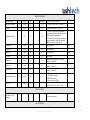
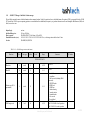
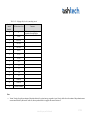
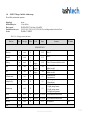
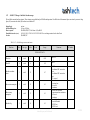
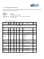
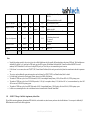
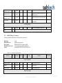
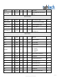
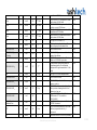
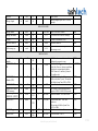
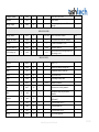
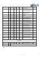
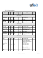
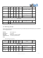
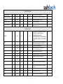
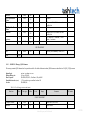
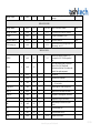
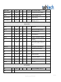
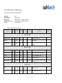
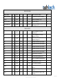
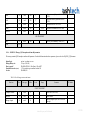
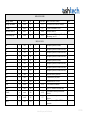
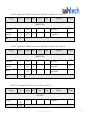
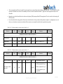
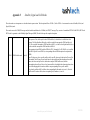
REVISION HISTORY
Track the revision history of the ATOM format Interface Control Document.
Release
1.00
1.01
Date
Jan 15, 2009
Feb 28,
2009
1.02
March 31,
2009
1.03
April 30,
2009
1.04
May 31,
2009
1.05
October 15,
Author
Comments
Initial creation
Style changes, misprints fixes
ATOM RNX section corrected
ATOM BAS section completed
Appendix C modified
Appendix E modified
ATOM PVT TTS message description added
Antenna name message meaning extended
ATOM PVT COO block modified by adding position type clarifier
Invalid GNSS time tag specified
ATOM DAT EXT message modified/clarified
ATOM ATR SNS message reserved
ATOM PVT SVS block modified
Azimuth and Elevation definition clarified
Defaults of ATM PVT message changed
Adding serial interface to request second PVT message
ATOM PVT SVS block description clarified
Definition of PRR data clarified
GLONASS almanac description corrected
Some re-formatting of the text performed per StephaneM request
Few minor changes made in Section 4 to reflect ATM,HED message
Appendix E is modified in section E.5
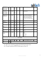
Ashtech Property and Confidential
2/208
2009
1.06
October 23,
2009
1.07
November
2, 2009
1.08
December
ATOM PVT PRR block is clarified
ATOM,RNX message finalized (in part of extended observation data)
Serial interface related with REF block of ATOM RNX/BAS is added
(section 4.5.)
Notes regarding ¼ cycle carrier alignment, pseudo-range smoothing and
clock steering are added for ATOM,RNX
Clarification of Sat usage and diff status flags in ATM,PVT,SVS
Intermediate changes in ATOM BAS message description (still not
finalized)
Some editorial changes done in different parts of the Manual
New group (EVT, section 3.10) added; corresponding changes are added to
other sections
ATOM,PVT,TTS message is moved to EVT group
Some fields (AFxxx) description is moved to Appendix G
The description of ATM,HED is moved to Appendix G
Appendix H removed
Accepting all the previous changes
Fixing misprints
Syntax changes towards releasing the Manual for user
Additional clarification of some fields and serial interface
Words ‘GNSS platform’, ‘MB500’ etc are removed
ATOM Logo added
$PASHSQ,ATM,PAR described in Section 4
ATOM ATR SNS message removed
Antenna type (AF006) field description is moved to Appendix G
Appendix G is reformatted
Some fields in ATM,ATR,OCC/AOP are clarified
Section 3.10 is reformatted
Style changes and clarifications
Reference documents updated
The description of ATM,RNX serial interface simplified
The description of ATM,RNX/BAS customization re-fined
Fields AF007 and AF008 are put to Appendix G
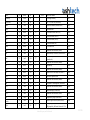
Ashtech Property and Confidential
3/208
15, 2009
1.09
1.10
January 15,
2010
February
10, 2010
1.11
March 10,
2010
1.12
April 15,
2010
1.13
May 31,
2010
Few style changes done towards releasing the Manual for end user
Code quality flag meaning in ATM,RNX,SCN,0 is extended
Message B1S is transferred to new STA group under the name BLA
Message SNS (Sensors data) is added to ATR group
Field AF006 is clarified
Some style corrections added
User cases of different RNX scenarios are clarified in section 5
Magellan Pro changed to Ashtech
PVT solution type field (AF009) introduced
Style changes from Patrice done towards releasing 1.09 as user Manual
Description of ATOM,BAS temporary removed (but section header is still
kept)
The above changes are accepted for more clear view of the changes which
follow
More clarifications added about generated position in section 2.4 and 2.5.
ATM,ATR,SNS corrected
Invalid states for position generated in PVT, MES and RNX are introduced
Receiver time status in ATM,RNX position block (Field AF010) introduced
Style corrections
Wn field in ALM is clarified
Mentioning of $GPRRE message removed
Misprint in time tag description fixed
Style corrections
Invalid values for some RNX fields clarified
ATM STA BLA message clarified
AF006 field clarified
ATM,ATR,SNS message modified
Field AF011 introduced in ATM,RNX header
Section 2.4 modified
Block ATM,PVT,LDP is added
Block ATM,PVT,CDC is added
Reference documents dates updated
Ashtech Property and Confidential
4/208
1.14
June 30,
2010
1.15
July 31,
2010
1.16
Aug 31,
2010
1.17
Sept 30,
2010
1.18
Nov 19,
2010
PVT solution ID clarified in section 3.4.
Correction usage status clarified in section 3.4.10
Time interval usage clarified for DAT and STA messages in sections 3, 4
Notes about clock steering effect on position added to 3.4.4 and 3.8.5
TT1 message mention is added to Appendix G.2
The response to $PASHQ,PAR,ATM is updated
Added note in 2.5 about possible GLONASS observation corrections to
golden Ashtech receiver
Reference documents dates updated
Message STA,BLA modified: earlier reserved fields are now populated
Message STA,DDS introduced
Message STA,DPS introduced
Message STA,RSA introduced
Message STA,RSP introduced
Message STA,EGB introduced
Few clarification sentences added to ATM,PVT and ATM,DAT description
Description of field AF006 (Appendix G.1) clarified
New ATM,NAV message for Galileo Ephemeris introduced but not
finalized
New ATM,DAT message for Galileo Navigation data stream introduced but
not finalized
GALILEO indication bits are added to PVT and RNX messages (GALILEO
as primary GNSS system is not yet defined)
Few clarifications are given for STA messages
Message ATM,STA,DDS is modified
Message ATM,STA,DLS is added
The logic to output ATM.STA messages is clarified
Bits/bytes boundaries and offsets are finalized in ATM,STA messages
A number of misprints indicated by System Test fixed.
Field AF003 clarified for invalid position (Appendix G)
Sat health indication is added to RNX message
Some details of receiver clock estimation/steering clarified in section 2.5
Local meteo parameters message added to ATR group
Ashtech Property and Confidential
5/208
2.01
Jan 24, 2011
2.02
Feb 28,
2011
2.03
Mar 31,
2011
2.04
Apr 29,
2011
Carrier shift message added to ATR group
APIS message added to PVT group
GNSS clock offset message added to STA group
Sat health message aged to STA group
Some MSM related changes are added to ATM,RNX and some additional
clarifications are given
Section G.3 is introduced in Appendix G
New signals definitions added to signal Mask (Appendix E)
The size of Sat and Signal mask is increased which led to reporting ver.2 in
headers of ATM,RNX and ATM,PVT messages. See also Appendix E.
Few extensions/clarifications are given for some ATM,RNX fields
Field AF002 adds 2 more choices
Field AF017 introduced
Antenna height field added to STA,RSP message
ATM,MES description removed (but section header is still kept)
Some CQ fixes reflected
Few misprints corrected
The description of ATOM version switch command added
The description of standard and fine resolution is added to ATOM RNX
The difference between v.1 and v.2 was better clarified in the text and
newly created Appendix H
Galileo Ephemeris message updated (but it is still not finalized)
PIS block is removed from PVT message
Few misprints corrected
Number 0 is claimed to be reserved for ATOM DBG group
Bit mask definitions clarified in section 3.2.
Some clarifications added to Section 4
Mentioning fields AF001 and AF004 removed
Section G.4 added
Message DLS modified
Exact definition for Satellite, Signal and Cell mask is added with reference
to RTCM-3 MSM fields DF394, DF395, DF396
Message ATM,ATR,SAH is added
Ashtech Property and Confidential
6/208
2.05
May 31,
2011
2.06
June 30,
2011
2.07
July 31,
2011
2.08
August 30,
2011
2.09
September
30, 2011
Message ATM,STA,AST is added
Clarifications are given for AF002 and AF009 in ATM,PVT header.
New FST group created with single message PIS
New STA message (SSC) created
New ATM,PVT sub-block (ROT) created
New ATM,DAT,INT message created
A number of clarifications are given for ATM,STA messages
Some corrections/additions for ATM,RNX to match latest MSM changes
ATR,CSD message is removed as not needed anymore
Appendix C is extended with RNX data restoration algorithm
Appendix G is extended with description of data link effective ATM,RNX
scenario for moving base RTK
New fields (or reserved positions) are introduced for ATM,PVT
Section 6 (ATOM Utilities) updated
Signal, Satellite and Cell masks description updated
Detailed clarification of Signals and Satellite IDs is provided for GPS; other
GNSS will be updated later
Section G.5 added
Detailed clarification of Signals and Satellite IDs is provided for
GLONASS, SBAS and GALILEO
Message ATM,DAT,GAL finalized
Message ATM,DAT,FRM introduced
Field AF006 is reintroduced; it is supposed that later user will use AF019
instead.
Message 4095,15 is introduced
More clarifications for ATM,PVT header IDs added
Max age of DDS message clarified
A comment added to carrier polarity indicator in RNX message
DDS message modified, Field AF012 clarified in Appendix G
Number of ATM,PVT fields clarified
BLN block now can report the assumption about applied clock drift model
Field AF020 (request ID) is introduced in ATM,PVT header
Block ATM,PVT,ROT finalized
Ashtech Property and Confidential
7/208
2.10
October 30,
2011
2.11
November
30, 2011
2.12
December
30, 2011
January 30,
2012
2.13
2.14
February
28, 2012
2.15
March 31,
2012
2.16
April 30,
2012
GPS and GLONASS almanac messages clarified
Appendix G modified in different entries, mainly to address field AF020
introduction
FST group is renamed to SUP group
Two messages of SUP group finalized
Message STA,GFN introduced
Message STA,GFN finalized
ATM,DAT,FRM message modified
Messages ATR,RIO and ATR,CFG added
Section 4.3 generalized
Sections 5.3 and 5.4 generalized and clarified
Section G.6 added
LDP and CDC blocks (ATM,PVT) are modified
Section G.6 removed as it is now a part of GNSS f/w platform PSD
Section 4 edited
Section 5 edited
Section 3.8 edited
Galileo EPH message finalized
Galileo EPH message updated to match final RTCM-3 MT 1045 changes
The definition of cycle slip counter for ATM,RNX is clarified
Note about invalid data generation added to Section 3.1
Galileo almanac message added to NAV group
Galileo ephemeris message updated
Message STA,GFN modified
Message STA,BLA modified
Reference documents list updated
Note to section C.2 added
Misprint (int16->uint16) corrected for field E in ATM,NAV,ALM(GPS)
Galileo almanac message modified
Choice QZSS added to GNSS masks
ATOM PVT message edited
New block for ATOM PVT is reserved: LMP
Section 2.4 is added with short overview of multiple ATOM PVT output
Ashtech Property and Confidential
8/208
2.17
June 30,
2012
2.18
July 24,
2012
2.19
Aug 15,
2012
2.20
Sep 25,
2012
Sep 28,
2012
Sep 30,
2012
Oct 12,
2012
2.21
2.22
2.23
2.24
Nov 24,
2012
Section 4.9 added with additional serial interface in case of advanced PVT
modes
Field AF020 clarified
Field AF023 reserved
New block for ATOM PVT is created: LMP
Extra notes added to section 2.4 about local positions/projections
QZSS Sat and Signals ID description added
Message ATM,ATR,CPB created
Message ATM,DAT,FRM finalized
Some CQ entries addressed
QZSS ephemeris message added
QZSS almanac message added
Galileo Almanac message updated
Message ATR,CPB updated
Mentioning of MES and BAS completely removed
ATM,PVT,PRR block updated
Extended ATM,PVT blocks (local coordinates) updated
Additional possibility to extend ATOM are added to Section 2.1
Editorial changes, adding missed fields
Group DBG is renamed to ALR and described in given manual (section
3.12)
Two messages are added to SUP group
Some misprints corrected, some clarifications given
Code misprint cleaning
Modify valid range and invalid values for number of RNX,PVT,STA fields
PVT,LMP block modifications added
Message ATM,PVT,BSD introduced
ATM,ATR,CPB message corrected
NAV,GIT for Galileo and QZSS introduced
Fix bug in NAV,GIT, tot field
Ashtech Property and Confidential
9/208
ATM,ATR,CPB message corrected
Remove all GIOVE-A/B traces
Modify PVT,COO
Field AF023 clarified
Remove section G.4
2.25
Jan 30, 2013
Table 'Supported NAV messages' expanded with GAL and QZS GITs
Fix typo ATR,PCB -> ATR,CPB
Fix (data types) typos and modify structure for NAV,GIT for GAL
Modify ATM,NAV,&GFT, ATM,RNX, ATM,PVT&MIS GNSS time cycles
description
2.26
Feb 28,
2013
Fix date of 2.24 release
Fix ATM,NAV,&GFT, ATM,RNX, ATM,PVT&MIS GNSS time cycles
modulo value
GAL ionosphere offset and message length typos
First revision for Beidu Ephemeris, almanac, ion&utc message
Add Beidu GNSS id for all messages
Remove Section 3.3 Satellite, Signal and Cell Masks to Appendix I
2.27
2.28
Jun 20,
2013
Jul 10, 2013
A number of clarifications with BeiDou is provided in different sections
Add more clarifications for AF003 field
Appendix J added.
Section 6 reduced
Corrections made in different parts of text
OCC message copied to EVT group
Update of ATOM user Manual is branched from given release. The previous
release was branched from ver 1.12
Ashtech Property and Confidential
10/208
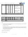
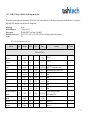
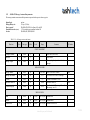
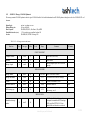
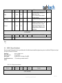
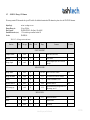
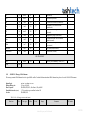
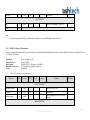
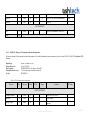
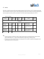
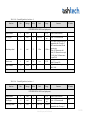
REFERENCE DOCUMENTS
Doc ID
RD1
RD2
RD3
RD4
RD5
RD6
RD7
Document Name
NMEA standard for communication between
marine electronic devices
RTCM recommended standards for differential
GNSS service – RTCM SC104
RTCM recommended standards for differential
GNSS service – RTCM SC104
GNSS firmware platform ICD
ATOM: Super Compact and Flexible Format to
Store and Transmit GNSS Data
The Receiver Independent Exchange Format
GNSS firmware platform PSD
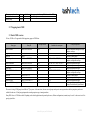
Date
01-Nov-2008
Version
4.00
NMEA
Author
20-Aug-2001
2.3
RTCM
March-2012
3.2
RTCM
N/A
15-Sep-2008
Latest
N/A
22-June-2009
N/A
3.01
Latest
Ashtech
I. Artushkin, A. Boriskin, D. Kozlov, the
paper presented on ION GNSS 2008
Werner Gurtner, Lou Estey
Ashtech
Ashtech Property and Confidential
11/208
CONTENT
1.
2.
WHAT IS ATOM AND WHAT CAN IT DO? ............................................................................................................................................................... 16
ATOM ORGANIZATION OVERVIEW ........................................................................................................................................................................ 17
2.1
Basic ATOM transport ............................................................................................................................................................................................. 17
2.2
Wrapping basic ATOM ............................................................................................................................................................................................ 18
2.3
Short ATOM overview ............................................................................................................................................................................................ 18
2.4
An example of ATOM PVT architecture ................................................................................................................................................................. 20
2.5
An overview of ATOM RNX observation message ................................................................................................................................................ 23
3. ATOM MESSAGES DESCRIPTION ............................................................................................................................................................................. 27
3.1
Messages generation mechanism ............................................................................................................................................................................. 28
3.2
Data Field Conventions ............................................................................................................................................................................................ 29
3.3
Satellite, Signal and Cell Masks .............................................................................................................................................................................. 32
3.4
ATOM PVT Message .............................................................................................................................................................................................. 33
3.4.1
ATOM PVT Message / Sub-Block: Position message .................................................................................................................................... 41
3.4.2
ATOM PVT Message / Sub-Block: Accuracy message .................................................................................................................................. 44
3.4.3
ATOM PVT Message / Sub-Block: Velocity message .................................................................................................................................... 46
3.4.4
ATOM PVT Message / Sub-Block: Clock message ........................................................................................................................................ 49
3.4.5
ATOM PVT Message / Sub-Block: Latency message..................................................................................................................................... 51
3.4.6
ATOM PVT Message / Sub-Block: Attitude message .................................................................................................................................... 53
3.4.7
ATOM PVT Message / Sub-Block: Baseline message .................................................................................................................................... 55
3.4.8
ATOM PVT Message / Sub-Block: Miscellaneous message .......................................................................................................................... 57
3.4.9
ATOM PVT Message / Sub-Block: Supplementary Attitude Data ................................................................................................................. 58
3.4.10
ATOM PVT Message / Sub-Block: Baseline Supplementary Data ................................................................................................................ 60
3.4.11
ATOM PVT Message / Sub Block: Pseudo-range residuals message ............................................................................................................. 62
3.4.12
ATOM PVT Message / Sub-Block: Satellite information message ................................................................................................................ 63
3.4.13
ATOM PVT Message / Sub-Block: Position expressed in local datum .......................................................................................................... 67
3.4.14
ATOM PVT Message / Sub-Block: Custom datum clarification .................................................................................................................... 69
3.4.15
ATOM PVT Message / Sub-Block: Position expressed in local cartographic projection ............................................................................... 70
3.5
ATOM ATR Messages ............................................................................................................................................................................................ 72
3.5.2
ATOM ATR Message / Antenna attributes ..................................................................................................................................................... 74
3.5.3
ATOM ATR Message / Receiver attributes ..................................................................................................................................................... 76
3.5.4
ATOM ATR Message / User message ............................................................................................................................................................. 77
3.5.5
ATOM ATR Message / Antenna offset parameters......................................................................................................................................... 79
Ashtech Property and Confidential
12/208
3.5.6
ATOM ATR Message / Site occupation information ...................................................................................................................................... 80
3.5.7
ATOM ATR Message / External Sensors Data .............................................................................................................................................. 82
3.5.8
ATOM ATR Message / Meteo Data ............................................................................................................................................................... 82
3.5.9
ATOM ATR Message / External Sensors Data Additional Header................................................................................................................ 83
3.5.10
ATOM ATR Message / Receiver Installed Options ........................................................................................................................................ 83
3.5.11
ATOM ATR Message / Receiver Configuration ............................................................................................................................................. 83
3.5.12
ATOM ATR Message / GLONASS Code-Phase Bias .................................................................................................................................... 83
3.6
ATOM NAV Messages ............................................................................................................................................................................................ 86
3.6.1
ATOM NAV Message / GPS Ephemeris ......................................................................................................................................................... 88
3.6.2
ATOM NAV Message / GLONASS Ephemeris.............................................................................................................................................. 91
3.6.3
ATOM NAV Message / SBAS Ephemeris ...................................................................................................................................................... 94
3.6.4
ATOM NAV Message / Galileo Ephemeris .................................................................................................................................................... 96
3.6.5
ATOM NAV Message / QZSS Ephemeris .................................................................................................................................................... 100
3.6.6
ATOM NAV Message / Beidou Ephemeris .................................................................................................................................................. 102
3.6.7
ATOM NAV Message / GPS Almanac ......................................................................................................................................................... 105
3.6.8
ATOM NAV Message / GLONASS Almanac .............................................................................................................................................. 106
3.6.9
ATOM NAV Message / SBAS Almanac ....................................................................................................................................................... 108
3.6.10
ATOM NAV Message / Galileo Almanac ..................................................................................................................................................... 110
3.6.11
ATOM NAV Message / QZSS Almanac ....................................................................................................................................................... 112
3.6.12
ATOM NAV Message / Beidou Almanac ..................................................................................................................................................... 114
3.6.13
ATOM NAV Message / GPS ionosphere and time shift parameters ............................................................................................................. 116
3.6.14
ATOM NAV Message / GPS full time parameters........................................................................................................................................ 118
3.6.15
ATOM NAV Message / GAL ionosphere and time shift parameters ............................................................................................................ 119
3.6.16
ATOM NAV Message / QZS ionosphere and time shift parameters ............................................................................................................ 121
3.6.17
ATOM NAV Message / BDS ionosphere and time shift parameters ............................................................................................................ 123
3.7
ATOM DAT Messages .......................................................................................................................................................................................... 126
3.7.1
ATOM DAT Message / GPS Raw Sub Frame .............................................................................................................................................. 128
3.7.2
ATOM DAT Message / GLONASS Raw String ........................................................................................................................................... 128
3.7.3
ATOM DAT Message / SBAS Sub Frame .................................................................................................................................................... 128
3.7.4
ATOM DAT Message / Galileo Raw Pages .................................................................................................................................................. 130
3.7.5
ATOM DAT Message / EXTernal port data .................................................................................................................................................. 130
3.7.6
ATOM DAT Message / INTernal receiver data ............................................................................................................................................ 133
3.7.7
ATOM DAT Message / Universal GNSS raw data frames ........................................................................................................................... 133
3.8
ATOM RNX Message ........................................................................................................................................................................................... 135
13/208
Ashtech Property and Confidential
3.8.1
Message structure and header ........................................................................................................................................................................ 136
3.8.2
GNSS header .................................................................................................................................................................................................. 142
3.8.3
Satellite data ................................................................................................................................................................................................... 145
3.8.4
Signal data ...................................................................................................................................................................................................... 146
3.8.5
Reference position.......................................................................................................................................................................................... 148
3.8.6
Extended ATOM RNX data ........................................................................................................................................................................... 155
3.9
ATOM SUP Messages ........................................................................................................................................................................................... 160
3.10 ATOM EVT Messages........................................................................................................................................................................................... 161
3.11 ATOM STA Messages ........................................................................................................................................................................................... 162
3.12 ATOM ALR Messages .......................................................................................................................................................................................... 162
4. ATOM SERIAL INTERFACE ...................................................................................................................................................................................... 163
4.1
Getting started ........................................................................................................................................................................................................ 163
4.2
Using the Extended Serial Interface for Sub-Message & Sub-Block Customization ............................................................................................ 164
4.3
Using the Extended Serial Interface for Observables Scenario Customization ..................................................................................................... 166
4.4
Encapsulation ......................................................................................................................................................................................................... 168
4.5
Output to virtual port.............................................................................................................................................................................................. 168
4.6
ATOM RNX scheduling among different transmissions ....................................................................................................................................... 168
4.7
ATOM version ....................................................................................................................................................................................................... 168
4.8
Querying ATOM Setup .......................................................................................................................................................................................... 168
4.9
Multiple ATOM PVT generation ........................................................................................................................................................................... 168
5. COMPRESSION OPTIONS FOR ATOM RNX OBSERVABLES ............................................................................................................................. 170
6. ATOM UTILITIES ........................................................................................................................................................................................................ 171
Appendix A:
$PASHR transport decoding sample.......................................................................................................................................................... 172
Appendix B:
ATOM message decoding sample ............................................................................................................................................................. 173
Appendix C:
Decomposition for ATOM RNX observables ........................................................................................................................................... 176
C.1. General principles to decompose original observables .......................................................................................................................................... 176
C.2. Explicit algorithm to restore original observables ................................................................................................................................................. 178
Appendix D:
Decimation for ATOM RNX observables ................................................................................................................................................. 187
Appendix E:
Data identifiers for ATOM RNX observables ........................................................................................................................................... 188
E.1. Satellite mask ......................................................................................................................................................................................................... 188
E.2. Signal mask ............................................................................................................................................................................................................ 188
E.3. Capability mask...................................................................................................................................................................................................... 190
E.4. Cell mask................................................................................................................................................................................................................ 190
E.5. Example of building Satellite, Signal and Cell Masks........................................................................................................................................... 191
14/208
Ashtech Property and Confidential
E.6. Example of interpreting Satellite, Signal and Cell Masks ..................................................................................................................................... 193
Appendix F:
Throughput figures for ATOM RNX observables ..................................................................................................................................... 196
Appendix G: Miscellaneous............................................................................................................................................................................................. 198
Appendix H: The summary of ATOM v.1/v2 differences............................................................................................................................................... 198
H.1. Satellite and Signal Masks in ATOM,PVT (SVS block) ....................................................................................................................................... 198
H.2. Satellite and Signal Masks in ATOM,RNX (GNSS observables block) ............................................................................................................... 198
H.3. Extended data resolution in ATOM,RNX (GNSS observables block) .................................................................................................................. 198
Appendix I:
Satellite, Signal and Cell Masks ................................................................................................................................................................ 200
Appendix J:
Example of ATOM masking table for a particular product ....................................................................................................................... 208
Ashtech Property and Confidential
15/208
1.
WHAT IS ATOM AND WHAT CAN IT DO?
Ashtech has developed its own proprietary binary data format, named “AshTech Optimized Messaging” (“ATOM” acronym for short), to adapt to the new GNSS reality and meet all
user requirements. The name emphasizes the main distinguishing ATOM feature, which is its ability to present data in compact form. ATOM is open to further extensions with new
messages or updates for already existing messages (the ATOM version number is provided for each message). Not all the ATOM fields need to be aligned by integer bytes boundaries.
However, for extra convenience, some fields have been grouped together to fit the integer number of bytes.
The key features of ATOM include:
Delivering the widest variety of GNSS data at any update rate
Supporting different customization options, from maximally compact to maximally full
Being in line with existing RTCM-3 and NMEA messages as well as RINEX-3 format
Backward compatibility with legacy Ashtech proprietary messages
Easily upgradable to include new versions and/or new messages
Universal presentation form for different GNSS data
Capability to use ATOM for raw data recording and as a differential correction protocol
ATOM can be used as the only GNSS data source for different applications. It can also be used in conjunction with existing (including legacy) Ashtech proprietary and standardized
data protocols.
The use of a standardized RTCM-3 transport layer allows 3rd party software to detect/synchronize ATOM messages easily.
Depending on their applications, users can take advantage of some particular ATOM messages (e.g. receiver positioning results only), or use the full ATOM function, including
generating raw data, providing reference data (base mode) and many others.
GNSS has grown rapidly in recent times. More and more GNSS-related applications have appeared, and new requirements for GNSS data have been formulated. Particularly:
Ease of use and universal support of different GNSS and their signals
Generating data with high update rate
Allowing compact data presentation to save room on the storage device and/or data link bandwidth
ATOM meets all these new requirements.
Ashtech Property and Confidential
16/208
2.
ATOM ORGANIZATION OVERVIEW
Although a proprietary message, ATOM uses the standardized RTCM-3 transport layer. This decision was made to allow any 3 rd party vendor to decode ATOM using available RTCM3 decoders.
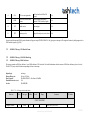
2.1 Basic ATOM transport
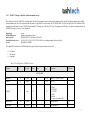
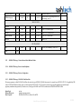
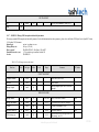
RTCM-3 message numbers range from 1001 to 4095. Numbers 4001 through 4095 are reserved for proprietary usage. Each vendor can ask RTCM to assign a unique number from this
range to be used exclusively for its own data. The number 4095 is reserved for Ashtech and is used by ATOM. As a result, the transport layer used by ATOM is the same as the one of
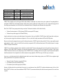
any standardized RTCM-3 message:
Preamble
Reserved
Message Length
8 bits
6 bits
10 bits
11010011
Not defined – set to
000000
Message length
in bytes
Variable Length Data Message 1
Variable length, integer number of bytes.
Known message 4095 (ATOM) is here
0-1023 bytes as specified in Message Length block
Variable Length Data Message 2
CRC
Variable length, integer number of bytes. The
content can be unknown for older ATOM
versions
24 bits
QualComm definition
CRC-24Q
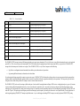
Similarly to RTCM-3, ATOM reserves a possibility for potential future extension for each existing ATOM message. These extensions may be introduced by adding data to the end of
any ATOM message This flexibility leads to the following claims:
Actual message length (as decoded from message header) may not match (be greater than) the minimal required message length (as dictated by the content of any particular
ATOM message).
Decoding software shall omit (ignore) any extra block of data at the end of ATOM message. Availability of such extra data shall be considered as a normal occasion and shall
not result in raising warning flag.
Encoding software shall NOT use this possibility for undocumented proprietary data transmission. No any extra information shall be added to the end of MSM message by
encoding software unless this would comply with the next releases of ATOM Manual.
If the original known 4095 message does not contain an integer number of bytes, then the needed number of zero bits (0 to 7) is added at the end of the message to make the whole
number of bytes an integer.
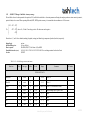
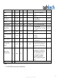
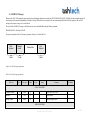
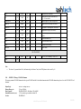
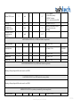
The high-level presentation form of message 4095 is the following:
Data item
Message number
Number
of Bits
Range
12
1001-4095
Comments
111111111111=4095 reserved for Ashtech
Ashtech Property and Confidential
17/208
Message group sub-number
Message version number
Message body
4
3
<=8165
0-15
0-7
Message group clarifier (e.g. 0011=3 reserved for PVT)
ATOM message version. Set to 1 or 2 for this release
2.2 Wrapping basic ATOM
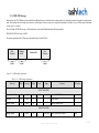
2.3 Short ATOM overview
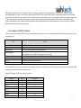
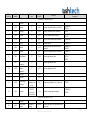
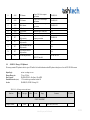
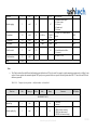
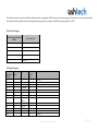
To date, ATOM ver.1/2 supports the following primary groups of GNSS data:
Group type
Group ID
Message clarifier
Standardized counterparts
Receiver alarms
4095,0 or ATOM,ALR
0000
N/A
Supplementary data
Reserved
Positioning results
4095,1 or ATOM,SUP
4095,2
4095,3 or ATOM,PVT
0001
N/A
0011
NMEA-3 GGA, GST,GSV etc
Receiver attributes
Navigation information
Data frames
GNSS RINEX observables
4095,4 or ATOM,ATR
4095,5 or ATOM,NAV
4095,6 or ATOM,DAT
4095,7 or ATOM,RNX
0100
0101
0110
0111
RTCM-3 1007, 1008, 1029, 1033
RTCM-3 1019, 1020
N/A
RINEX-3, RTCM-3 MSM
Reserved
Receiver status
Receiver events
Any non-RTCM-3 message
4095,8/9/10/11/12
4095,13 or ATOM,STA
4095,14 or ATOM,EVT
4095,15
1101
1110
1111
N/A
N/A
N/A
Group configuration
Group of independent messages or single,
composite message.
Group of independent messages
Reserved for future group
Group of independent messages or single,
composite, configurable message
Group of independent messages
Group of independent messages
Group of independent messages
Group of independent messages or single,
composite, configurable message
Reserved for future groups
Group of independent messages
Group of independent messages
Just transport layer to pack any other
message. Not described in given Manual
The most of existing ATOM groups is available for 3rd party users. At the same time, there are reserved groups and respective messages numbers which are proprietary and are not
available for end users. If third party equipment detects such groups/messages, it must ignore them.
Group RNX refers to ATOM observables. Depending on the desired application and personal preferences, different configurations (scenarios) may be used. A short overview of this
group is given below.
Ashtech Property and Confidential
18/208
Group PVT delivers positioning results such as position, velocity, clock offset, and Satellite tracking/usage status. Additionally it contains the information about position latency and
accuracy. These data can be converted to, or generated from standardized NMEA-3 messages. A more detailed view on the ATOM PVT architecture is given in a separate section
below.
Group ATR generates receiver/antenna attributes, for example receiver name/serial number/firmware version and/or antenna name/serial number. It is also used to specify the antenna
reference point with respect to survey point as well as any user-defined message generation.
Group NAV generates navigation data extracted from GNSS data streams. NAV supports the generation of GPS, GLONASS, SBAS, GALILEO, QZSS, BEIDOU ephemeris and
almanac data as well as some other valuable information, like broadcast ionosphere parameters.
Group DAT generates a raw navigation data stream (frames) decoded from any signal a GNSS receiver tracks. Also, this group includes messages containing the binary streams
entering the receiver through its physical ports (e.g. external differential data stream).
Group STA provides status information from some receiver firmware modules. Particularly it can output the current receiver configuration parameters, the differential data link status,
etc.
Group EVT generates some information about events inside a receiver. It can be the precise time-tagging of the external event marker or PPS time-tagging.
Group ALR is very valuable for identifying receiver problems. These messages are supposed to inform end user about receiver problems or incorrect setups. Each (available for end
user) alarm supposes clear set of user actions to restore normal receiver operation. These messages are parts of Ashtech Trouble Log, so called atl.log file which customer can request
from any Ashtech receiver in case of problems.
Group SUP contains various data needed mostly to supplement position (PVT) and raw (RNX) data for some specific applications.
There is a special group 4095,15 which intentionally has no 3-letter name assigned. This group is not described in given Manual. This group is a simplest packing frame to encapsulate
any other non-RTCM-3 message for special applications.
In future, ATOM is open to adding more groups to the currently supported list.
Each group contains a number of particular sub-messages/sub-blocks, which can optionally be enabled or disabled. Each group has its own default configuration, which can be receiver
-type and firmware-version dependent.
Some ATOM messages have fixed length, some others have variable length. Variable length can be caused by the fact that this message contains multiple satellite information (i.e. Nsat
dependent). On the other hand, variable length can be caused by some internal switches in the message header defining different presentation forms for the data that follow.
Most of the data ATOM generates are extracted from GNSS signal(s) directly using internal receiver algorithms. These are GNSS observables and navigation data as well as internal
receiver positioning results. On the other hand, some ATOM fields refer to receiver hardware configuration or user-entered parameters. For example, a lot of generated attributive
information refers to either receiver configuration (e.g. receiver name, serial number, firmware version, etc.) or to some user-entered settings (e.g. antenna name, antenna offset against
ground mark, ASCII message, fixed reference position, etc.).
Ashtech Property and Confidential
19/208
While the general organization of all the ATOM groups is similar, there are however some differences. Messages or groups SUP, ATR, NAV, DAT, STA and EVT are always
generated independently of each other. At the same time, messages of groups RNX and PVT can be output differently. Each of these groups contains a unique header often defining
which data blocks follow this header. If for example, a receiver is configured to generate more than one block of data for a given group, these data blocks can be grouped within a single
message (under the same header and inside the same transport frame) or can be split into sequential and independent transmissions. In the latter case, each independent message
provides a so-called multiple-message bit allowing the decoding equipment to compile complete data epochs from sequential transmissions. The next two sections give examples of
different transmission strategies for these groups of messages.
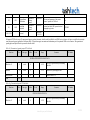
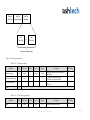
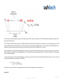
2.4 An example of ATOM PVT architecture
A closer look at the organization of the ATOM PVT message for example shows that it starts with a 10-byte header containing the following data (for exact presentation, please refer to
the dedicated section):
Field
Message number
Message sub-number
Message version
Multiple message bit
Number of satellites
Primary GNSS system
Time tag
Reserved bits
Comment
111111111111=4095, reserved for Ashtech
0011=3, reserved for PVT
001=1, refers to the first version of the ATOM PVT message
1 indicates that more 4095,3 message(s) will follow for the same time tag
0 indicates that it is the last ATOM PVT message tagged to a given time tag
Number of GNSS satellites (visible, tracked, used in position)
Defines the meaning of time tag and position datum
Presentation depends on primary GNSS system
For future use
Note that multiple-GNSS receivers make an assumption about the primary GNSS system used (default is usually GPS). When a primary GNSS system is specified, then the ATOM
message time tag and position datum refer to that primary system.
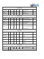
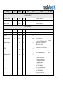
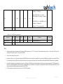
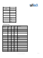
Currently the following primary PVT data sub-blocks are supported.
Block type
Position
Accuracy
Velocity
Clock
Latency
Attitude
Baseline
Miscellaneous
Block ID
COO
ERR
VEL
CLC
LCY
HPR
BLN
MIS
Size, in bytes
26
10
12
10
3
11
16
23
Ashtech Property and Confidential
20/208
Attitude supplementary data
Baseline supplementary data
Original datum clarification
Local datum position
Local map projection
Satellites status
ROT
BDS
CDC
LDP
LMP
SVS
13
19
Depends on message content
Depends on message content
Depends on message content
Depends on tracking status
ATOM,PVT allows outputting receiver position tagged to different points, including L1 antenna phase center, antenna reference point or ground mark. Corresponding identifier is
provided inside ATOM,PVT body. Antenna height (the height of antenna reference point above ground mark) is usually provided, so user can re-compute position tagging as he/she
wants. Having requested antenna name, user is also able to make ease transformations between L1 antenna phase center and antenna reference point positions.
Block COO of ATOM,PVT message outputs position referring to some datum. This datum can be indicated as ‘default’ which is defined by:
The datum of broadcast ephemeris (i.e. IGS05 realization of ITRF2005 on current epoch if GPS is primary)
The datum reference position is tagged to (for RTK and DGNSS only)
It must be noted that often it is not known a priori what the datum of reference position is. In this case, block MIS of ATOM,PVT indicates ‘default’ datum which is actually correct
only if reference position is tagged to the same datum as used ephemeris are. If it is not so, then ‘default’ actually means unknown for RTK and/or DGNSS positions.
Many users can be interested in getting position in some specific local datum and/or projection. ATOM,PVT applies the ideology that block COO always reports originally computed
position (indicated as ‘default’ or ‘custom’ in block MIS), while extra block(s) can output block LDP (Local Datum Position) and/or LMP (Local Map Projection). See complete
ATOM,PVT description for detailed formats.
ATOM,PVT is open to adding more sub-blocks in future. It should also be noted that Ashtech PVT data are usually output under the same header (possibly with a unique update rate for
each block), i.e. inside a single ATOM,PVT transmission. On the other hand, each particular sub-block (e.g. COO or SVS) can be output under its own header, i.e. using a separate
ATOM,PVT transmission. In the latter case, the multiple-message bit in the ATOM,PVT header is set accordingly to allow the receiving entity to compile complete position epoch data
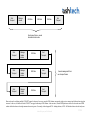
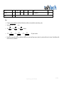
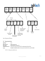
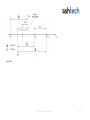
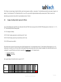
from different transmissions. The two diagrams below show different transmission strategies applicable to ATOM PVT messages (3 sub-blocks are given as examples).
In some cases, e.g. when Network provider delivers additional information about the source datum, local datum and map projections, extra ATM,PVT blocks can supplement original
position generated in block COO. In general these extra blocks clarify:
The name of the datum COO position is expressed in (CDC block)
COO coordinates expressed in a local datum (LDP block)
COO coordinates expressed in local map projection (LMP block)
Sometimes, a clarification about reference position datum is known a priori (e.g. source datum name from so called RTCM-3 coordinate transformation messages). In this case, block
MIS of ATOM,PVT will indicate ‘custom’ datum and additional ATOM,PVT block CDC (custom datum clarification) which clarifies the name and parameters of this ‘custom’ datum
is generated.
Ashtech Property and Confidential
21/208
Start
Transport
Message
Header
ranspo
COO Data
ERR Data
SVS Data
End
Transport
One transport frame – several
information blocks inside
Start
Transport
Message
Header
ranspor
COO Data
End
Transport
Start
Transport
Message
Header
ranspor
ERR Data
End
Transport
Start
Transport
Message
Header
ranspor
SVS Data
End
Transport
Several messages with their
own transport frames
More words must be said about multiple ATOM PVT output. In the most of user cases, complete GNSS solution corresponds to single receiver antenna, single dedicated correcting data
stream etc. In this case, all sub-blocks inside ATOM PVT are tagged to this unique GNSS solution. At the same time, Ashtech GNSS platform can deliver to end user advanced GNSS
solution which includes more than single antenna and correcting source. For example, Ashtech supports RTK + heading solution, or RTK + Full altitude solution where obviously more
Ashtech Property and Confidential
22/208
than single antenna and corresponding corrections/observations are used. For such advanced GNSS solutions, user can be supplied with more than single PVT message, each
responsible for particular GNSS solution. Thanks for generic structure of PVT message, these multiple PVT output can be decoded by the same parser, but receiving entity must
interpret these multiple PVT messages correctly. To do this, ATOM PVT generator provides special identifying information inside ATOM PVT header (so called Request ID).
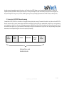
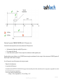
2.5 An overview of ATOM RNX observation message
It contains blocks of GPS, GLONASS, etc., observables as well as optional reference position (static or moving). Presentation of observables is exactly the same for each GNSS. This
allows the same source code to be used to construct and parse each GNSS observation block. Each of these blocks can be transmitted inside a single message, or can be spread among
several transmissions as shown below. In latter case, decoding equipment must process Multiple Message Bit (available in the header of each observation message) properly. It must be
also noted that in some specific cases (e.g. when the number of tracked Signals is too high), the observation data for a single GNSS can be also spread among several sequential
transmissions; in this case Multiple Message Bit is also set to allow complete epoch compiling.
Start
Transport
Message
Header
ranspo
GPS Data
GLONASS Data
Reference
Position
End
Transport
One transport frame – several
information blocks inside
Ashtech Property and Confidential
23/208
Start
Transport
Message
Header
ranspor
Start
Transport
Message
Header
ranspor
Start
Transport
Message
Header
ranspo
GPS Data
End
Transport
GLONASS Data
End
Transport
Reference Position
End
Transport
Several messages with
their own transport frames
RNX message presents receiver data directly in RINEX-3 like manner. The variety of GNSS and their signals is almost unlimited in RNX messages, because it uses universal and
flexible data identification. Group RNX can support a number of compact data presentation options making it usable both for raw data recording and as an effective differential
protocol.
Since ATOM RNX message allows different customization and optimization scenarios to be implemented, a number of additional explanations/clarifications are provided in
Appendixes C, D and E. These Appendixes allow users to understand in more details what algorithmic background is behind RNX observation message.
ATOM RNX observation message can generate the following primary observables for each tracked signal (RINEX definitions):
Pseudo-range (C)
Carrier phase (L)
Doppler (D)
Signal strength (S)
Since there is still some ambiguity in interpretation, the statements below clarify the definition of the observables packed into ATOM RNX messages:
Time tags, pseudo-ranges and carrier phase for each GNSS correspond to RTCM-3 and RINEX conventions
Ashtech Property and Confidential
24/208
All pseudo-ranges and carrier phases (at least for a given GNSS) are supposed to be controlled by the same receiver clock
All carrier phases are matched to their respective pseudo-ranges
Any C-L, C–C or L-L combination is flat provided continuous carrier tracking is achieved. Only ionosphere and some other effects can cause slow divergence of one
observable against another
Doppler is interpreted as the true carrier phase derivative, i.e. the Doppler sign is equal to the delta-carrier sign
Signal strength corresponds to the RTCM-3 definition (Carrier-to-Noise Ratio) and is expressed in dBHz
All the generated observables are raw, i.e. not corrected for any specific (e.g. atmospheric) effects. In addition, the statements below enumerate what corrections are applied, or can
possibly be applied to original ATOM RNXobservations.
All the GNSS observables are steered for the same receiver clock value. The clock error in all observables does not exceed about 300 meters. Some observation messages can
provide the value of original clock, which can be used to restore original (not steered) observables.
All carrier phases corresponding to the same GNSS and band are aligned with each other, i.e. the possible ¼ cycle (or other) bias is properly compensated for.
The initial integer count in all carrier phases is set to match the carrier phase and respective pseudo-range at carrier initialization epoch
Pseudo-ranges can be smoothed by carrier phases to reduce the noise/multipath error. Some ATOM observations messages can provide the so-called smoothing residual
allowing the unsmoothed pseudo-range value to be restored.
All ATOM observables are never compensated for antenna specific biases. On the other hand, original receiver observations can be matched to the desired virtual antenna
name. The corresponding (physical and virtual) antenna names can be provided by ATR messages, thus making it possible if needed to restore the observations corresponding
to the physical antenna.
All ATOM observables are never compensated for receiver specific biases. On the other hand, original GLONASS receiver observations can be corrected to the golden
Ashtech receiver type to make GLONASS double difference observations unbiased between given and golden receiver.
The optional reference position which can be generated inside ATOM observation messages is supposed to be referred to proper ITRF epoch year which is usually indicated inside
ATOM body. Reference position in ATOM RNX can be tagged to different points including L1 phase center, antenna reference point and ground mark. Usually antenna height (the
height of antenna reference point above ground mark) is provided together with reference position, so user can re-compute reference point position to ground mark position and vice
versa. Also antenna name can be requested from receiver to allow transformation between L1 antenna phase center and antenna reference point.
Reference position in ATOM RNX can be either static (e.g. entered) position or can be kinematic (moving) position receiver computes each epoch. Latter case allows using RNX as
differential data generated by moving receiver. The accuracy indicator of reference position can be also provided.
With multiple GNSS tracking, the definition of receiver clock offset and clock steering must be clarified. Internally receiver can estimate own clock offset against each of available
GNSS time scales. Each epoch, some GNSS is selected as primary. Primary GNSS can affect up to:
time tag presentation for some messages
default datum for output position
the reference time system when generating receiver clock offset estimate and making clock steering
Receiver clock offset estimate generated in PVT and RNX messages always refers to primary GNSS system specified in the header of these messages. Clock steering procedure applies
this clock estimate equally to all GNSS observables. Receiver clock estimates against all GNSS scales receivers currently supports are output via STA messages group.
Ashtech Property and Confidential
25/208
Ashtech Property and Confidential
26/208
3.
ATOM MESSAGES DESCRIPTION
This chapter contains the detailed (bit-to-bit) description of messages supported by ATOM format ver.1/2. A short summary of principal differences between v.1 and v.2 is provided in
Appendix H. The following ATOM groups are described:
Positioning results: ATOM PVT
Attributes data: ATOM ATR
Navigation data: ATOM NAV
Raw binary data: ATOM DAT
GNSS observations: ATOM RNX
Supplementary data: ATOM SUP
Status information: ATOM STA
Events information: ATOM EVT
Receiver alarms: ATOM ALR
It should be noted that ATOM messages described here are not all necessarily supported by all Ashtech receivers and in all firmware versions. Corresponding warning is provided in
Product Manuals (see Appendix J as an example). Some of ATOM messages can be supported outside a GNSS receiver in different service procedures and/or PC tools. Also the reader
should be aware that some indicators inside some ATOM messages can be set as follows:
Adaptively, depending on the current receiver status, or
To a fixed value, depending on user settings, or
To some hard-coded value, depending on particular hardware/firmware combinations.
The messages are described independently of each other to allow the reader to concentrate efficiently only on a group of interest. That is why redundant information is introduced in
each description, some general comments being repeated for a number of particular messages/fields. Before starting with a particular message, the reader should first be introduced to
the generalized organization of the ATOM group that the given message belongs to.
When describing a message, some short information is provided on how it can be requested, what the basic principles are to output this message and what additional cross-information
can be interesting regarding the message content and request. The mechanism used to generate ATOM messages is not part of the ATOM standard, but is usually independent of the
receiver and firmware version. That is why the reader should not only understand the content of an ATOM message, but also learn how it can be requested and output from a receiver.
For a complete description of the ATOM serial interface please refer to the corresponding section.
Ashtech Property and Confidential
27/208
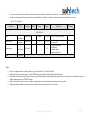
3.1 Messages generation mechanism
Any ATOM message can usually be generated onto any available receiver port independently of each other. When describing the serial interface we mention <Port Name> as a
substitute for the actual receiver port (A, B etc). The same ATOM message can be requested through more than one port and possibly with different intervals and parameters.
The time priority of one ATOM message over another ATOM message within the same epoch can be receiver/firmware dependent. The time priority of ATOM messages against nonATOM data within complete epoch data is also receiver/firmware dependent.
When requested, each ATOM message is generated using a specific combination of the following principles:
On new
On change
On time
On event
‘On new’ means that the corresponding message is output immediately after being requested. ‘On change’ means that the corresponding message is output only after its content has
changed. ‘On time’ means that the corresponding message is output on a regular basis, according to the requested time interval x. ‘On event’ means that a message can be generated,
with its content tagged to some event in the receiver.
In some cases however, there is no obvious interpretation as to what is behind such or such output principle. For example ‘on event’ can be interpreted as ‘on change’ if the event refers
to a change in some receiver state. Nevertheless, in most cases, the meaning is quite clear.
For example, the ATOM PVT message is primarily output using the ‘on time’ principle. If for example it is requested at an interval of x=0.5 seconds, then it will be output at receiver
time tags corresponding to each integer and half-an-integer second. In some specific cases, the ATOM PVT message is output using the ‘on event’ principle. If for example the receiver
is configured to output the so-called Time Tagged (or synchronous) RTK position, then ATOM PVT will be tagged to events when new RTK base data arrive at the rover, are decoded
and processed by the RTK engine. But since in most cases, RTK base data arrive at the rover with equal intervals and stable latency, the ‘on event’ principle is here somehow equivalent
to the ‘on time’ principle.
All ATOM DAT messages are output using the ‘on change’ principle, i.e. there is no need to specify an interval for outputting them. Each message is generated once the content of the
receiver data buffer containing corresponding data has been updated, i.e. changed. In order to have unified serial interface pattern, one still can specify interval to output DAT messages,
but this interval will be ignored.
ATOM,STA messages could be output using the ‘on change’ principle, i.e. a message is generated once the content of the receiver data buffer containing corresponding data has been
updated i.e. changed. At the same time, most users can want to see STA messages with some preset interval and Ashtech implemented this strategy. In this case user can miss some
internal status updates (if more than one internal update occurred between consecutive STA messages). Or user can get identical information in two consecutive STA messages if there
was no any internal update between them.
Ashtech Property and Confidential
28/208
Most of the ATOM NAV messages are output by combining the ‘on new / on change / on time’ principles. For example, if the ATOM NAV / EPH message is requested at an interval
of x=600 seconds, then ephemeris data for a given satellite will be output immediately after request (‘on new’), and then in x=600 seconds (‘on time’) etc. If new ephemeris data (new
IODE) for this satellite are decoded, these will be output immediately (‘on change’) and the counting of the interval of x=600 seconds will start from this moment.
About NAV messages, which serve all tracked satellites, it should be understood that such a rule is applied to each satellite independently. In order to save the overall peak throughput,
no more than one NAV message is output over a single 1-second epoch. In other words, the minimal interval between any NAV messages is one second, while the nominal interval
between NAV messages with fixed content is x seconds (e.g. 600). If the specified interval x is too short to allow all requested NAV messages to be output (one message per second)
within this interval, then x will be set internally as low as necessary to satisfy the output strategy.
The x interval between messages cannot be chosen arbitrarily. For ‘fast’ messages, only the following intervals are valid: 0.05/0.1/0.2/0.5 sec. If a receiver supports higher update rates,
then intervals 0.02 sec (50 Hz), 0.01 sec (100 Hz) and 0.005 sec (200 Hz) are also admissible. The phase of ‘fast’ messages is chosen in order to ‘acquire’ integer seconds of primary
GNSS time. For ‘slow’ messages, any integer second interval is admissible (provided it is less than 999 sec). However, for the RNX group, only the following intervals are supported:
1/2/3/4/5/6/10/12/15/20/30/60/120 etc each integer minute of primary GNSS time (provided it is less than 15 minutes). The ‘phase’ of these messages is chosen in order to ‘acquire’
integer minutes of primary GNSS time. These intervals and shifts are recommended in RTCM-2 standard and ‘are kept in mind’ for all the other standards.
Messages of the PVT group support the same intervals as the RNX group. But in case of integer second intervals, the ‘phase’ of PVT messages is chosen in order to acquire integer
minutes of UTC (and not primary GNSS) time. Assuming a 2-sec interval is selected for the RNX and PVT groups, GPS is the primary GNSS used and the GPS-UTC time shift is 15
sec (as from January 1, 2009 until June 30, 2012), then RNX and PVT will always be output for different time tags:
Each even second of GPS time tag will contain RNX data
Each odd second of GPS time tag (or each even second of UTC time tag) will contain PVT data.
Some ATOM messages being requested will be generated regardless their content is valid or not. E.g. ATM,PVT,COO data will be generated if receiver cannot compute position or
computed position is internally recognized as invalid. In this case, position components will take pre-specified invalid value; at the same time, other fields in ATM,PVT,COO still can
report valid values.
On contrary, some other ATOM messages being requested can stop outputting if their content is invalid or no longer actual. Say a particular NAV message (e.g. EPH with expired age
of validity) is not output. Or messages of STA group (e.g. differential decoder status) stop outputting in case their content was not updated during some time.
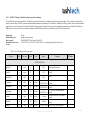
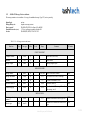
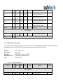
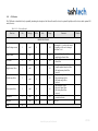
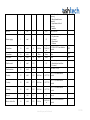
3.2 Data Field Conventions
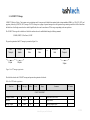
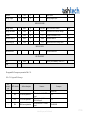
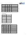
Each of the binary Data Fields (DF) described below fits one of the types presented in the following table.
Data type
Description
Range
bitX
Bit field, each bit is 0 or 1
X is the length of the bit field
0, 1
Example / Notes
bit2: 2-bit field
bit11: 11-bit field
Ashtech Property and Confidential
29/208
X
0 to (2 – 1)
uintX
X bit unsigned integer
intX
X bit 2`s complement integer
±(2
intSX
X bit sign-magnitude integer
±(2
char(X)
8-bit character set with total
length in X chars
Character set with
variable length
utf8(X)
Unicode UTF08 Code Unit
Unicode set with variable length
uint8: 8-bit unsigned integer
X-1
– 1)
int8: 8-bit 2`s complement integer
X-1
– 1)
intS14: 14-bit sign-magnitude integer
(see notes below)
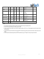
Note:
The intS data type refers to a sign-magnitude value. The sign-magnitude representation records the number's sign and magnitude. MSB is 0 for positive numbers and 1 for
negative numbers. The rest of the bits are the number’s magnitude. For example, for 8-bit words, the representations of numbers "-7" and "+7" in a binary form are 10000111
and 00000111, respectively. Negative zero is not used.
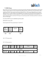
The convention used for the Most and Least Significant Bits (MSB and LSB) for signed and unsigned data is presented in the diagram below.
Data follow this direction
Bit location in N-bit integer
N-1
MSB
.....
3210
LSB
ATOM uses a number of bit masks (indicated as field bitX) referring to GNSS set being transmitted (GNSS mask), Satellites being present (Satellite mask), Signals available (Signal
mask) and many others. In all these masks the first bit is the bit with goes first in binary stream and the last bit is the bit which goes last in binary stream.
Ashtech Property and Confidential
30/208
To insure quick reference to ATOM data fields, numerical equivalents to some of them are provided. Some ATOM data fields are the exact copy of the corresponding standardized
RTCM-3 data fields, some are unique to the ATOM format. That is why ATOM data fields having exact RTCM-3 counterparts are marked as DFxxx. For example, data field ‘Message
Number’ (uint12, 4095 reserved for Ashtech) is referenced as DF002. If reference to a data field is given in form ‘see DF…’, then it means that described field has something common
with standardized DF but does not copy it exactly. Some other ATOM data fields, which are intended for proprietary use only, are referenced as AFxxx, where xxx is a unique number
assigned to a given field. All the other fields are not marked.
The description below refers to ATOM ver. 1/2. Further ATOM versions will be marked with higher version numbers. The version number is provided inside each ATOM message
(header). The 3rd party decoding equipment should check the version number before parsing the message and make no attempt to interpret it if the detected version number is higher
than the currently supported one. Generally, a higher ATOM version number does not guarantee backward compatibility with the previous versions unless the decoder is updated for the
new ATOM version.
Some ATOM messages contain reserved fields. 3rd party users should ignore all these fields. With ATOM development, some initially reserved fields (usually defined as zero) can
become meaningful. Since 3rd party users ignore them, these changes should not hurt anyone. However, in some cases, newly introduced fields can play a vital role in the interpretation
of other ATOM fields. In this case, the version number of the corresponding ATOM message will be increased and the corresponding Manual update (or Amendment) will be issued.
Some ATOM fields contain reserved states (e.g. ‘supplementary follow’ field in ATOM RNX, which contains one reserved state). ATOM ver. 1/2 does not generate these states, but
new ATOM versions could. If a newly introduced state can play a vital role in parsing ATOM data, then the version number of the corresponding ATOM message will be increased and
the corresponding Manual update (or Amendment) will be issued.
Some ATOM fields reserve one state to indicate an invalid value (e.g. invalid carrier phase). At the same time, some supplementary fields (e.g. corresponding SNR) can be still valid.
Also, on rare occasions, some supplementary fields can take arbitrary values if the ‘primary’ field is indicated as invalid. In all these cases, the decoding equipment should process
correctly (i.e. ignore) invalid fields and be careful with the interpretation of the corresponding supplementary fields.
In almost all the messages, ATOM generates field DF003 (reference station ID). This is the correct name if a receiver is used as reference station. However, if a receiver is not used as a
reference station, DF003 field is still used as generalized indicator for a receiver.
Ashtech Property and Confidential
31/208
3.3 Satellite, Signal and Cell Masks
All information is moved to “Appendix I : Satellite, Signal and Cell Masks”
Ashtech Property and Confidential
32/208
3.4 ATOM PVT Message
ATOM PVT (Position, Velocity, Time) outputs receiver positioning results. It can generate all valuable data contained in the existing standardized NMEA (e.g. GGA, GSV, GST) and
proprietary Ashtech (e.g. PBN, POS, SAT) messages. The PVT message is not a group of separated messages but a solid generic message containing a number of sub-block data. Some
sub-blocks have fixed length, some others have variable length. Besides, there can be more than one PVT message corresponding to the same epoch time.
The ATOM PVT message with its default set of sub-blocks and intervals can be enabled/disabled using the following command:
$PASHS,ATM,PVT,<Port Name>,ON/OFF
The general organization of the PVT message is presented on Figure 3.4.a.
Start
Transport
Message
Header
3 bytes
10 bytes
Sub-Block 1
Data
Sub-Block 2
Data
.....
Sub-Block N
Data
End
Transport
3 bytes
Figure 3.4.a. PVT message organization
The table below sketches the ATOM PVT message and presents the organization of its header.
Table 3.4.a. PVT header organization
Data item
Bits
Data type
Offset
Scale
Range
Comments
DF Number
START TRANSPORT
Transport Preamble
8
uint8
0
Set to 0xD3 (HEX Code)
Reserved
6
Bit6
8
Set to 000000
Message Length
10
unt10
14
Message length in bytes
Ashtech Property and Confidential
33/208
MESSAGE HEADER
4095 is reserved for Ashtech
DF002
Message number
12
uint12
24
1001-4095
Message sub-number
4
uint4
36
0-15
3 is reserved for ATOM PVT message
Version
3
uint3
40
0-7
Multiple message bit
1
bit1
43
0-1
Antenna ID
4
uint4
44
0-15
ATOM version number, set to 1 or 2
1 : other PVT message(s) corresponding to
given antenna ID, engine ID and request ID
will be output for given time tag
0 : no other PVT message(s) corresponding
to given antenna ID, engine ID and request
ID will be output for given time tag
See Appendix G
AF019
Engine ID
6
uint6
48
0-63
See Appendix G
AF002
Request ID
4
uint4
54
0-15
See Appendix G
AF020
Reserved
5
bit5
58
0-31
Nsats used
6
uint6
63
0-63
Nsats seen
6
uint6
69
0-63
Nsats tracked
6
uint6
75
0-63
Primary GNSS system
2
uint2
81
0-3
Time Tag
21
Bit21
83
Set to 00000
Number of used satellites, 63 means not
defined, 62 means 62+
Number of visible satellites, 63 means not
defined, 62 means 62+
Number of tracked satellites, 63 means not
defined, 62 means 62+
0: GPS is primary
1: GLONASS is primary
2: BEIDOU is primary
3: reserved for other GNSS
Refers to the primary GNSS system time
scale (see tables 3.4.b, 3.4.c and 3.4.d
MESSAGE DATA
Sub-blocks of PVT
message
See sub-sections below
END TRANSPORT
Ashtech Property and Confidential
34/208
CRC
24
uint24
24-bit Cyclic Redundancy Check (CRC)
Total
Notes:
Unlike with other ATOM groups, the station ID is not provided in the ATM,PVT header. But it can be available in extended form (four Characters) in the ATM,PVT MIS
block.
ATOM version switch (1 or 2) affects the content of SVS block only (see below)
The receiver usually features a number of basic PVT sub-engines; each of them (or some of their combinations) can deliver user position at given epoch, Field AF002 provides
the information what PVT sub-engine(s) configuration delivered position results. In general, field AF002 can change with epochs depending on environmental conditions
and/or the differential data link status. E.g. when data link stops for a long time, initially reported AF002=9 can transit to AF002=6.
ATM,PVT is generic message and in some specific cases user can request a number of different PVT-style messages. So with multiple ATM,PVT messages referring to given
time tag, end user must understand which messages corresponds to serial commands he/she issued to request them. Field AF020 allows user to match each decoded message
with corresponding $PASHS,ATM,*** command request.
It is supposed that up to more than one antenna connector can serve a particular GNSS board so antenna ID (AF019) is provided. For each h/w configuration each antenna
connector can have its own unique index. For MB500 GNSS board, only antenna connector 1 is available. For MB100 GNSS board, two antennae connectors are available:
antenna connector 1 refers to so called external antenna and can process L1/L2 signal, while antenna connector 2 refers to so called internal antenna and can process L1 signal
only. For other future Ashtech boards there can be other relationships, but user Manual for each board exactly specifies what antenna connector index refers to. The antenna
name which is generated in ATM,ATR,ANM message always refer to antenna corresponding to connector reported in this header. The complete status of each potentially
available antenna is supposed to be seen via other message (see ATM,STA,AST).
Usually all the data corresponding to the same antenna ID, engine ID, and request ID are generated within single PVT message (i.e. all blocks under the same header).
However for some hardware targets and firmware versions, position data corresponding to the same IDs can be spread over more than one transmission. In this case M-bit is
set as described to help PVT listener to compile complete PVT epoch corresponding to particular set of antenna ID, engine ID and request ID.
Ashtech Property and Confidential
35/208
Primary
Time Tag
Time Tag
extension type
Time Tag
extension
Full
Time Tag
or
Fine
Time Tag
Depends on extension type
Figure 3.4.b. Time tag organization
Table 3.4.b. Time tag presentation
Data item
Bits
Data type
Offset
Scale
Range
Primary time tag
12
uint12
0
1 second
0-3599
Time tag extension type
1
bit1
12
Time tag extension
8
Total
21
0-1
13
Comments
DF Number
GNSS time modulo 1 hour, 4095 means
invalid time
1: fine time tag extension follows
0: full time tag extension follows
Primary time tag extension (see table
below)
Table 3.4.c. FULL Time tag presentation
Data item
Bits
Data type
Offset
Scale
Range
Ashtech Property and Confidential
Comments
DF Number
36/208
Hour
5
Day
uint5
3
uint3
0
5
1 hour
1 day
0-23
0-7
GNSS hour within GNSS day
Set to GPS day (0…6) within GPS week, 0
is Sunday, 1 is Monday etc.
Set to GLONASS day (0…6) within
GLONASS week, 0 is Sunday, 1 is Monday
etc.
Se to BDS day (0…6) within BDS week,, 0
is Sunday, 1 is Monday etc.
In each case, 7 refers to unknown day
Total
8
Table 3.4.d. FINE Time tag presentation
Data item
Bits
Data type
Offset
Scale
Range
Fractional second
8
uint8
0
5 ms
0-995
Total
8
Comments
DF Number
GNSS time modulo 1 sec
Notes:
The time tag always refers to the time scale of the primary GNSS system used, i.e. UTC + Nls (where Nls is the number of leap seconds, i.e. 15 as from Jan 1 2009, and 16 as
from July 1 2012 for GPS, and UTC+3 hours for GLONASS.
The size of the time tag is always fixed.
Using the switchable time tag presentation, users can cover a full range of GNSS time tags with fine resolution. If the time tag is an integer second, the ATOM generator will
insert full extension information to reduce whole time tag ambiguity down to a week number. If the time tag is a fractional second, then the ATOM generator will insert a fine
time tag extension thus allowing data to be generated at up to 200 Hz.
If a leap second occurs, the primary time tag is set to 3600
The supported PVT sub-blocks are presented in Table 3.4.e.
Table 3.4.e. Supported PVT sub-blocks
Ashtech Property and Confidential
37/208
PVT sub
block type
ASCII
identifier
0
Sub-block name
Block size,
bytes
Reserved
Data block
Comments
ID/subID
GENERAL PURPOSE BLOCKS
0000
1
COO
Position
26
0001
Position, flags, differential age, base ID etc
2
ERR
Accuracy
10
0010
Accuracy (lat/lon/alt errors covariance)
3
VEL
Velocity
12
0011
Velocity estimates and its attributes
4
CLK
Clock
10
0100
Receiver clock estimates and its attributes
5
LCY
Latency
3
0101
6
HPR
Attitude
11
0110
7
BLN
Baseline
16
0111
Position latency
Heading, pitch and roll estimates and its
attributes
3D baseline components and its attributes
8
MIS
Miscellaneous
23
1000
Position supplementary data
9
ROT
10
BSD
11
Extended Attitude
Parameters
Extended
Baseline
parameters
Reserved
12
Reserved
13
PRR
Pseudo-range
Residuals
14
SVS
Sat status
13
19
1001
Counterpart
$PASHR,POS
$GPGGA
$GPGST
$PASHR,POS
$GPVTG
$PASHR,PBN
$PASHR,LTN
$PASHR,ATT
$GPHDT
$PASHR,VEC
$GPRMC
$GPGGA
$GPZDA
Attitude supplementary data
N/A
Baseline supplementary data
N/A
1101
Pseudo-range Residuals for L1 signal only
$GPGRS
1110
Satellite tracking/usage information
$PASHR,SAT
$GPGSV
1010
1011
1100
Depends on
tracking/usage
statust
Depends on
ATM,PVT
version and
tracking status
SPECIAL BLOCKS (1111)
15,0
15,1
LDP
Reserved
Local Datum
Position
00000000
Depends on
message
00000001
Position from block COO expressed in local
user datum
Ashtech Property and Confidential
N/A
38/208
content
15,2
CDC
Custom Datum
Clarification
15,3
LMP
Local Map
Projection
15,4-15,255
Depends on
message
content
Depends on
message
content
00000010
00000011
The name and parameters of the custom
datum of position in COO block
N/A
Position from block LDP expressed in local
cartographic projection
$GPGMP
0000010011111111
Reserved
All supported PVT blocks (except 15) output general-purpose position information, which is usually available for each GNSS receiver/firmware. In future, reserved blocks can contain
some extra general purpose position data. In contrast, block 15 (Special messages) can contain some information specific to particular GNSS receiver/firmware. The organization of
general-purpose and special blocks is presented in the tables below.
Table 3.4.f. Presentation of general purpose PVT sub-blocks
Data item
Bits
Data type
Offset
Scale
Range
Comments
DF Number
GENERAL PURPOSE SUB-BLOCK DATA
Block size, X
8
uint8
0
0-255
The size of given block in bytes including
this field
Block ID
4
uint4
8
0-14
Reserved for general purpose data
Sub block data
Total
12
Each of blocks 0-14
8*X
Table 3.4.g. Presentation of special PVT sub-blocks
Data item
Bits
Data type
Offset
Scale
Range
Comments
DF Number
SPECIAL SUB-BLOCK DATA
Block size, X
8
uint8
0
0-255
The size of given block in bytes including
this field
Ashtech Property and Confidential
39/208
Block ID
4
uint4
8
15
Special block sub-ID
8
uint8
12
0-255
Special sub block data
Total
20
Reserved for a variety of special data
Special data block ID
Each of blocks 15,0-255
8*X
The next sections present the structure of each of the currently supported sub-blocks in the ATOM PVT message. Each PVT sub-block is described independently of each other. It is
supposed that generally more than one sub-block can follow the ATOM PVT header.
Ashtech Property and Confidential
40/208
3.4.1
ATOM PVT Message / Sub-Block: Position message
This sub-block contains the most valuable information about computed position. Usually, the position refers to the default datum of the primary GNSS system specified in the ATOM
PVT header. But ATOM is open to outputting position on a custom datum. Some additional (not operative yet) position information can be sent through the Miscellaneous (MIS) subblock, but at a lower rate.
Output Logic:
Sub-block Binary size:
How to request?
Permissible intervals x (sec):
See also:
on time
26 bytes (208 bits)
$PASHS,ATM,PVT,<Port Name>,ON,x,&COO
0.05/0.1/0.2/0.5/1/2/3/4/5/6/10/12/15/20/30/60/120 etc., each integer minute but less than 15 min
$PASHR,POS; $GPGGA
Table 3.4.1.a Sub-Message structure and content
Data item
Bits
Data type
Offset
Scale
Range
Comments
DF Number
SUB-BLOCK DATA
Block size
8
uint8
0
0-255
Set to 26
Block ID
4
uint4
8
0-15
Set to 1
Position type (GGA
presentation)
4
uint4
12
0-15
GNSS usage mask
8
bit8
16
0-255
0: invalid fix
1: standalone
2: diff corrected (including SBAS
corrected)
3: GPS PPS mode
4: RTK fixed
5: RTK float
6: dead reckoning
7: entered position
8: simulator mode
9-14: reserved
15: not defined
Bit1: GPS is used in position
Bit2: GLONASS is used in position
Bit3: GALILEO is used in position
Ashtech Property and Confidential
41/208
Position mode
3
uint3
24
0-7
Position smoothing
3
uint3
27
0-7
Reserved
4
bit4
30
0-15
PDOP
10
uint10
34
HDOP
10
uint10
44
X coordinate
38
int38
54
0.1 mm
Y coordinate
38
int38
92
0.1 mm
Z coordinate
38
int38
130
0.1 mm
Differential position age
10
uint10
168
1 sec
Base ID
12
uint12
178
0-4095
Position type clarifier
4
uint4
190
0-15
Differential link age
10
uint10
194
Reserved
4
uint4
204
Total
0.1
0-102.2
0.1
1 sec
0-102.2
+/-13743895.3471
m
+/-13743895.3471
m
+/-13743895.3471
m
0-1023
0-1023
Bit4: SBAS (ranging) is used in
position
Bit5: QZSS is used in position
Bit6: Beidou is used in position
Bit7-8: Reserved for other GNSS
0: 3D GNSS position
1: 2D position with entered altitude
2: 2D position with ‘frozen’ altitude
3-6: reserved
7: not defined
0: not smoothed
1: averaged static position
2: smoothed kinematic position
3-6: reserved
7: not defined
Set to 0…0
Corresponds to satellites used (102.3 if
not defined or invalid)
Corresponds to satellites used (102.3 if
not defined or invalid)
-13743895.3472 m if not defined or
invalid
-13743895.3472 m if not defined or
invalid
-13743895.3472 m if not defined or
invalid
Age of differential corrections applied
to PVT (1023 if not defined or invalid,
1022 if valid but >1022)
Base station ID
See Appendix G
Age of differential data link (1023 if
not defined or invalid, 1022 if valid but
>1022)
See Appendix G
DF025
DF026
DF027
DF003
AF003
Differential
link age
AF023
208
Notes:
Ashtech Property and Confidential
42/208
If invalid fix is reported, some supplementary fields (e.g. Base ID or differential age) can still have some sense.
If position is invalid, then position type clarifier (AF003) contains the cause of invalid position.
With at least one GPS or GLONASS or GALILEO or QZSS or SBAS or BeiDou (ranging) satellite used in the position computation, the corresponding bit is set accordingly.
In differential SBAS, the base station ID is the PRN of the master (or primary) SBAS (120-158).
Some fields have a reserved state meaning “not defined”. This is because not all PVT engines can provide information for these fields.
The position type clarifier (AF003) is provided to specify in more details what is behind the standardized GGA-type position flag, e.g. to distinguish between DGNSS and
DSBAS.
All DOPs figures are computed assuming independent clock offset for each GNSS, i.e. in case of 3 GNSS systems used (GPS+GLONASS+GALILEO), GDOP matrix is 6x6
matrix.
Reported Differential position age refers to the difference between current time tag and the time tag to which applied original differential corrections are tagged (i.e. correction
project time).. Please note, that last received corrections in some cases can be not applied. So growing of differential position age does not always mean data link stop, but
indicates the degree of position degradation.
On contrary, Differential link age refers to the difference between current time tag and the time tag to which latest decoded corrections are tagged to. So growing differential link
age does mean failure on base or in communication.
Position is reported as Cartesian position. Geodetic position can be computed by user applying proper ellipsoid parameters. The datum bit (default or custom) is provided in MIS
block. If datum is ‘default’, then user must apply corresponding default ellipsoid parameters unique for GNSS specified as primary. If datum is ‘custom’, then its name and
ellipsoid parameters are available via additional CDC (custom datum clarification) block.
There is no guarantee that reported differential position is tagged to ‘default’ (specific for a GNSS system selected as primary) datum even it is claimed so. In fact, the datum will
be defined by the datum reference position is expressed in. There are evidences that some providers generate reference positions tagged to local datum w/o explicit specification
of this, e.g. some Network providers in US generate reference position in NAD83 without any mentioning of this.
Ashtech Property and Confidential
43/208
3.4.2
ATOM PVT Message / Sub-Block: Accuracy message
This sub-block refers to the data presented in the position (COO) sub-block described above. It contains parameters allowing the complete position covariance matrix (symmetric,
positive definite) to be restored. When reporting differential (RTK, DGPS) position accuracy, it is assumed that base coordinates are 100% accurate.
s11 s12 s13
S
s 22 s 23 , where s11, s22 and s33 are always positive. All other terms can be negative.
s33
Here indexes 1, 2, and 3 refer to latitude (northing), longitude (easting), and altitude (up) components of position (baseline) respectively.
Output Logic:
Sub-block Binary size:
How to request?
Permissible intervals x (sec):
See also:
on time
10 bytes (80 bits)
$PASHS,ATM,PVT,<Port Name>,ON,x,&ERR
0.05/0.1/0.2/0.5/1/2/3/4/5/6/10/12/15/20/30/60/120 etc each integer minute but less than 15 min
$GPGST
Table 3.4.2.a Sub-Message structure and content
Data item
Bits
Data type
Offset
Scale
Range
Comments
DF Number
SUB-BLOCK DATA
Block size
8
uint8
0
0-255
Set to 10
Block ID
4
uint4
8
0-15
Set to 2
Sigma
20
uint20
12
0.001 m
0-1048.574 m
k1
7
uint7
32
1/128
0…1
Have meaning only if Sigma is valid
k2
7
uint7
39
1/128
0…1
ditto
k3
7
uint7
46
1/128
0…1
ditto
r12
8
int8
53
1/128
-1…1
ditto
r13
8
int8
61
1/128
-1…1
ditto
1048.575 if not defined or invalid.
Ashtech Property and Confidential
44/208
r23
8
int8
69
Reserved
3
bit3
77
Total
80
1/128
-1…1
0-7
ditto
See Appendix G
AF021
Notes:
If Sigma is set to an invalid value, then all other fields in this sub-block are also invalid and can take arbitrary values.
Sigma=
s11 s22 s33
meter
s11
s 22
s33
; k2
; k3
all unitless
sigma
sigma
sigma
s13
s 23
s12
; r13
; r 23
r12
s11 s33
s 22 s33
s11 s 22
k1
all (‘square’) unitless
Reported covariance matrix needs not any additional scaling because reports actual 1sigma accuracy figures. E.g. random variable ratio1=err1/sqrt(s11) should theoretically
follow Gaussian (0,1) distribution.
Ashtech Property and Confidential
45/208
3.4.3
ATOM PVT Message / Sub-Block: Velocity message
This sub-block contains receiver velocity components.
Output Logic:
Sub-block Binary size:
How to request?
Permissible intervals x (sec):
See also:
on time
12 bytes (96 bits)
$PASHS,ATM,PVT,<Port Name>,ON,x,&VEL
0.05/0.1/0.2/0.5/1/2/3/4/5/6/10/12/15/20/30/60/120 etc each integer minute but less than 15 min
$PASHR,POS; $GPVTG
Table 3.4.3.a Sub-Message structure and content
Data item
Bits
Data type
Offset
Scale
Range
Comments
DF Number
SUB-BLOCK DATA
Block size
8
uint8
0
0-255
Set to 12
Block ID
4
uint4
8
0-15
Set to 3
X velocity
25
int25
12
0.0001 m/s
Y velocity
25
int25
37
0.0001 m/s
Z velocity
25
int25
62
0.0001 m/s
Velocity type
1
bit1
87
0-1
0: ‘instant’ velocity
1: ‘mean’ velocity
4
uint4
88
0-15
See table 3.4.3.b
4
bit4
92
0-15
See Appendix G
Doppler/velocity
smoothing interval
Reserved
Total
+/- 1677.7215
m/s
+/- 1677.7215
m/s
+/- 1677.7215
m/s
- 1677.7216 if not defined or invalid
- 1677.7216 if not defined or invalid
- 1677.7216 if not defined or invalid
AF022
96
Ashtech Property and Confidential
46/208
Table 3.4.3.b Mapping table for velocity smoothing interval
Smoothing
interval
identifier
Effective interval, sec
0
0
1
0-0.005
2
0.005-0.01
3
0.01-0.02
4
0.02-0.05
5
0.05-0.1
6
0.1-0.2
7
0.2-0.5
8
0.5-1
9
1-2
10
2-3
11
3-4
12
4-5
13
Reserved
14
Reserved
15
No interval defined
Comment
Refers to instant velocity
computed with rough Doppler
Notes:
‘Instant’ velocity refers to the true estimate of the position derivative for a given time tag, as opposed to ‘mean’ velocity, which refers to the estimate of the position increment
on some interval divided by this interval. In this case, the true position derivative is tagged to the center of this interval.
Ashtech Property and Confidential
47/208
In case of ‘instant’ velocity, the smoothing interval is that of the corresponding Doppler/velocity filter. In case of ‘mean’ velocity, the smoothing interval is the exact interval
of integrated Doppler. In this case, the smoothing interval is equal to the upper bound value corresponding to the selected Smoothing interval identifier. For example, with
Smoothing interval identifier=10, the smoothing interval is 3 seconds.
Ashtech Property and Confidential
48/208
3.4.4
ATOM PVT Message / Sub-Block: Clock message
This sub-block contains receiver clock offset parameters.
Output Logic:
Sub-block Binary size:
How to request?
Permissible intervals x (sec):
See also:
on time
10 bytes (80 bits)
$PASHS,ATM,PVT,<Port Name>,ON,x,&CLK
0.05/0.1/0.2/0.5/1/2/3/4/5/6/10/12/15/20/30/60/120 etc each integer minute but less than 15 min
$PASHR,PBN
Table 3.4.4.a Sub-Message structure and content
Data item
Bits
Data type
Offset
Scale
Range
Comments
DF Number
SUB-BLOCK DATA
Block size
8
uint8
0
0-255
Set to 10
Block ID
4
uint4
8
0-15
Set to 4
Clock steering
1
bit1
12
0-1
External clock
1
Bit1
13
0-1
Receiver clock offset
30
int30
14
0.001 m
Receiver clock drift
22
int22
44
0.001 m/s
TDOP
10
uint10
66
0.1
Reserved
4
bit4
76
Total
80
+/-536870.911
m
+/- 2097.151
m/s
0-102.2
0-15
1: clock steering is applied
0: clock steering is not applied
1: external clock is used
0: internal clock is used
-536870.912 if not defined or invalid
-2097.152 if not defined or invalid
102.3 if not defined or invalid
Set to 0000
Notes:
A receiver can apply or not apply the so-called clock steering procedure. However the receiver clock offset and drift reported in this message always refer to the original
(internal) receiver clock, which is typically within +/-300 km or so.
A receiver can be clocked from an internal or external (usually very stable) oscillator. The corresponding bit is therefore provided.
Ashtech Property and Confidential
49/208
Reported receiver clock offset and drifts (as well as TDOP value) refers against primary GNSS system specified in PVT message header
It must be noted that clock steering procedure affects reported position (block COO) for very high dynamic receiver. In this case, user who desires to return to original receiver
status (not steered) will have to correct reported position (COO) using the knowledge of reported receiver velocity (block VEL) and internal clock offset (given block).
Ashtech Property and Confidential
50/208
3.4.5
ATOM PVT Message / Sub-Block: Latency message
This sub-block contains latency of given ATM,PVT message.
Output Logic:
Sub-block Binary size:
How to request?
Permissible intervals x (sec):
See also:
on time
3 bytes (24 bits)
$PASHS,ATM,PVT,<Port Name>,ON,x,&LCY
0.05/0.1/0.2/0.5/1/2/3/4/5/6/10/12/15/20/30/60/120 etc each integer minute but less than 15 min
$PASHR,LTN
Table 3.4.5.a Sub-Message structure and content
Data item
Bits
Data type
Offset
Scale
Range
Comments
DF Number
SUB-BLOCK DATA
Block size
8
uint8
0
0-255
Set to 3
Block ID
4
uint4
8
0-15
Set to 5
Latency
12
uint12
12
Total
24
1 ms
0-4095
4095 if not defined or invalid, see also the
table 3.4.5.b
Table 3.4.5.b Mapping table for Latency
Latency
interval
identifier
0-4087
Effective interval,
msec
0-4087
Comment
Nominal mode
4088
4088-5000
Latency is within 4.088 to 5 seconds
4089
5001-6000
Latency is within 5 to 6 seconds
4090
6001-7000
Latency is within 6 to 7 seconds
Ashtech Property and Confidential
51/208
4091
7001-8000
Latency is within 7 to 8 seconds
4092
8001-9000
Latency is within 8 to 9 seconds
4093
9001-10000
Latency is within 9 to 10 seconds
4094
>10000
4095
Invalid latency
Latency is >10 seconds but still valid
Latency is not defined or invalid
Note:
This latency presentation table is intended to report latency with good resolution for conventional PVT modes when latency is typically below 1 second. On the other hand, in
specific positioning modes, such as synchronous (or Time Tagged) RTK, position latency is primarily defined by the data link latency, which can reach 10 seconds in some
cases. When latency is too high, then there is no need to report it with ms resolution.
The reported latency refers to the delay of the ATM,PVT output instance compared to the ATM,PVT time tag. This reported latency is unique for given ATM,PVT message
and may differ from the latency reported in the $PASHR,LTN message.
Ashtech Property and Confidential
52/208
3.4.6
ATOM PVT Message / Sub-Block: Attitude message
This sub-block contains attitude parameters.
Output Logic:
Sub-block Binary size:
How to request?
Permissible intervals x (sec):
See also:
on time
11 bytes (88 bits)
$PASHS,ATM,PVT,<Port Name>,ON,x,&HPR
0.05/0.1/0.2/0.5/1/2/3/4/5/6/10/12/15/20/30/60/120 etc each integer minute but less than 15 min
$PASHR,ATT; $GPHDT
Table 3.4.6.a Message structure and content
Data item
Bits
Data type
Offset
Scale
Range
Comments
DF Number
SUB-BLOCK DATA
Block size
8
uint8
0
0-255
Set to 11
Block ID
4
uint4
8
0-15
Set to 6
Heading
16
uint16
12
0-360
Value >360 means not defined or invalid
Pitch
16
int16
28
Roll
16
int16
44
Calibration mode
1
bit1
60
0-1
Ambiguity flag
1
bit1
61
0-1
Antenna setup
2
uint2
62
0-3
MRMS
10
uint10
64
0.001 m
0-1.022 m
Value > 90 & Value < -90 means not
defined or invalid
Value >90 & Value < -90 means not
defined or invalid
0: calibration mode
1: operation mode
0: fixed ambiguity
1: float ambiguity
0: 2 arbitrary moving antennae
1: 2 tightly moving antennae
2: 3 tightly moving antennae
3: 4+ tightly moving antennae
1.023 means not defined or invalid
BRMS
10
uint10
74
0.001 m
0-1.022 m
1.023 means not defined or invalid
Reserved
4
uint4
84
Total
88
0.01
degree
0.01
degree
0.01
degree
+/-90
+/-90
0-15
See Appendix G
Ashtech Property and Confidential
AF024
53/208
Note:
For the description of fields MRMS and BRMS, see ATT message definition.
The BRMS field is reported invalid if the lengths of baselines are not known a priori.
When antenna setup = 1,2,3, then reported angles refer to platform (where antennae installed on) attitude. When antenna setup=0, then reported heading refers to baseline
azimuth, reported pitch refers to baseline elevation, roll is reported as invalid.
When single baseline (2 antennae) is applied for attitude estimation, either pitch or roll (or both) is not available. When 2 and more baselines (3+antennae) are applied for
attitude estimation, all angles can be generally available. But in some singular cases, some of 3 angles can be not available even with 3+ antennae.
In case of single baseline, HPR block being transmitted with BLN block under the same PVT header indicates that HPR content is based on BLN estimate.
Ashtech Property and Confidential
54/208
3.4.7
ATOM PVT Message / Sub-Block: Baseline message
This sub-block contains baseline estimates. These estimates are applicable only to MS differential operation. Here MS refers to Measurement Space corrections by contract to Stage
Space (SS) corrections for which (SS) baseline is not defined at all.
Output Logic:
Sub-block Binary size:
How to request?
Permissible intervals x (sec):
See also:
on time
16 bytes (128 bits)
$PASHS,ATM,PVT,<Port Name>,ON,x,&BLN
0.05/0.1/0.2/0.5/1/2/3/4/5/6/10/12/15/20/30/60/120 etc each integer minute but less than 15 min
$PASHR,VEC
Table 3.4.7.a Sub-Message structure and content
Data item
Bits
Data type
Offset
Scale
Range
Comments
DF Number
SUB-BLOCK DATA
Block size
8
uint8
0
0-255
Set to 16
Block ID
4
uint4
8
0-15
Set to 7
Baseline coordinate
frame
3
uint3
12
0-7
Base motion assumption
2
uint2
15
0-3
Base accuracy
assumption
2
uint2
17
0-3
Baseline flag
2
uint2
19
0-3
0: XYZ
1: rectilinear ENU centered on
rover
2: rectilinear ENU centered on
base
3-7: reserved
0: static base
1: moving base
2: reserved
3: unknown
0: exact base coordinate
1: approximate base coordinates
2: reserved
3: unknown
0: invalid baseline
1: code differential
2: RTK float
3: RTK fixed
Ashtech Property and Confidential
55/208
Arrow option
1
Bit1
21
Baseline 1st component
35
int35
22
0.0001 m
+/- 1717986.9183 m
Baseline 2nd component
35
int35
57
0.0001 m
+/- 1717986.9183 m
Baseline 3rd component
35
int35
92
0.0001 m
+/- 1717986.9183 m
Common clock drift
mode
1
Bit1
127
Total
Note:
0-1
0-1
0: Arrow option is not applied
1: Arrow option is applied
- 1717986.9184 Means invalid
value
Ditto
Ditto
0: base and rover clocks
assumed different
1: base and rover clock drifts
assumed the same
128
Baseline components are expressed according to the value of “Baseline coordinate frame”.
Baseline refers to the vector between L1 antenna phase centers.
If the baseline flag is set to invalid, then the complete block must be considered as invalid and all the fields can take arbitrary values.
An invalid baseline estimate does not imply an invalid position in sub-block COO (e.g. standalone position for which baseline is not defined).
Valid COO and BLN blocks being tagged to the same PVT solution ID, source ID and antenna ID are related to each other by the simplest formulae: position=base+baseline,
where base is the coordinates of reference receiver (static or moving, physical or virtual).
Being expressed in XYZ, baseline does not depend on primary GNSS system (i.e. primary datum) reported. To convert XYZ baseline into any rectilinear ENU system proper
default ellipsoid model (corresponding to Primary GNSS system) is used.
Arrow option refers to using or not using a priori knowledge that given baseline has known fixed length. If fixed length is not known yet (e.g. Arrow calibration stage), then
given indicator reports 0.
Common clock drift indicator can be valuable for so called internal heading configuration or when base and rover boards are fed by external occilator.
Ashtech Property and Confidential
56/208
3.4.8
ATOM PVT Message / Sub-Block: Miscellaneous message
This sub-block contains various supplementary parameters. These are the data that usually change slowly and accompany position sub-block (COO) information. To save throughput,
this sub-block can be requested at a lower rate than the position sub-block.
Output Logic:
Sub-block Binary size:
How to request?
Permissible intervals x (sec):
See also:
on time
23 bytes (184 bits)
$PASHS,ATM,PVT,<Port Name>,ON,x,&MIS
0.05/0.1/0.2/0.5/1/2/3/4/5/6/10/12/15/20/30/60/120 etc each integer minute but less than 15 min
$GPGGA; $GPRMC; $GPZDA
Table 3.4.8.a Sub-Message structure and content
Data item
Bits
Data type
Offset
Scale
Range
Comments
DF Number
SUB-BLOCK DATA
Block size
8
uint8
0
0-255
Set to 23
Block ID
4
uint4
8
0-15
Set to 8
Site ID
32
char(4)
12
Position point
3
uint3
44
0-7
Reserved
2
uint2
47
0-3
The same as in $PASHR,PBN message
0: Antenna reference point
1: L1 phase center
2-5: Reserved
6: Ground mark
7: unknown
See Appendix G
Antenna height
16
uint16
49
Datum
1
Bit1
65
0-1
6
uint6
66
0-63
16
int16
72
12
uint12
88
Default datum
clarification
Geoid height
The number of GNSS
time cycles
0.0001 m
0.01m
0-6.5535
AF006
Value 6.5535 means 6.5535+
0: default
1: custom
DF028
63 if not defined or invalid
DF021
+/- 327.67
-327.68 if not defined or invalid
0-4095
For GPS wn modulo 4095 cycle
Ashtech Property and Confidential
57/208
For GLO day number of 4 year period
(DF129)
GPS-UTC time shift
6
uint6
100
Magnetic variation
16
int16
106
Local zone time offset
11
uint11
122
Type of used ephemeris
3
bit3
133
Firmware version
32
char(4)
136
Reserved
16
bit16
168
Total
184
1s
0.01
degree
1 min
0-63
+/-180
0-1439
0-15
0-
4095 means underfined or invalid
63 if not defined or invalid
Value > 180 & Value < -180 means not
defined or invalid
Value > 1439 if not defined or invalid
0: almanac used
1: broadcast ephemeris used
2-6: reserved
7: unknown
Reserved
See DF054
Set to 0…0
Notes:
3.4.9
Normally the position reported by the receiver refers to the so-called default datum, which is generally different depending on the primary GNSS used. The default datum can
additionally be clarified, e.g. by specifying the ITRF epoch year when GPS is primary (Default datum clarification field). It must be noted that field DF028 is not still
mandatory in RTCM document. It is now reserved to output ITRF epoch year. That is why user is recommended to ignore its content.
If field ‘datum’ is set to custom, then extra ATM,PVT,CDC (Custom Datum Clarification) block can be generated to clarify what this custom datum is and what its parameters
are.
The receiver can also additionally report position tagged to some local datum. See ATM,PVT,LDP (Local Datum Position) block for details.
For Geoid height, local zone time offset, magnetic variation, please refer to NMEA-4.0 definitions.
The number of GNSS time cycles refers to GPS Week number (0-4095; 0 starts midnight January5/January 6 1980, rolls from 4095 to 0) if GPS is primary system.
The number of GNSS time cycles refers to GLONASS day number (1-1461, day 1 corresponds to January 1 1996, rolls from 1461 to 1, zero means unknown day, values 14624095 are not used) if GLONAS is primary system.
The number of GNSS time cycles refers to BDS Week number (0-4095; 0 starts midnight January 1 2006 (Sunday), rolls from 4095 to 0) if BDS is primary system.
In all the cases, antenna height refers to the vertical distance between Antenna Reference Point and Ground Mark.
ATOM PVT Message / Sub-Block: Supplementary Attitude Data
This sub-block contains supplementary information to HPR sub-block, such as attitude rate, attitude accuracy and some other valuable indicators. User can request it additionally if
HPR information is not sufficient for his/her application.
Ashtech Property and Confidential
58/208
Output Logic:
Sub-block Binary size:
How to request?
Permissible intervals x (sec):
See also:
on time
13 bytes (104 bits)
$PASHS,ATM,PVT,<Port Name>,ON,x,&ROT
0.05/0.1/0.2/0.5/1/2/3/4/5/6/10/12/15/20/30/60/120 etc each integer minute but less than 15 min
N/A
Table 3.4.9.a Message structure and content
Data item
Bits
Data type
Offset
Scale
Range
Comments
DF Number
SUB-BLOCK DATA
Block size
8
Uint8
0
0-255
Set to 13
Block ID
4
Uint4
8
0-15
Set to 9
Heading speed
16
int16
12
0.01d/s
+/-327.67 d/s
-327.68 means invalid
Pitch speed
16
int16
28
0.01d/s
+/-327.67 d/s
-327.68 means invalid
Roll speed
16
int16
44
0.01d/s
+/-327.67 d/s
Heading rms error
10
uint10
60
0.01 d
0-10.23 d
Pitch rms error
10
uint10
70
0.01 d
0-10.23 d
Roll rms error
10
uint10
80
0.01 d
0-10.23 d
Extrapolation interval
10
uint10
90
10 ms
0-10230 ms
Reserved
4
bit4
100
-327.68 means invalid
10.22 means 10.22+
10.23 means invalid
10.22 means 10.22+
10.23 means invalid
10.22 means 10.22+
10.23 means invalid
0 means time tagged estimates
10230 means 10230+
See Appendix G
Total
Note:
AF017
104
Sign conventions for angular speed needs to be specified.
Accuracy reported as 0 (zero) does not mean invalid estimate. For example if heading is estimated by very long baseline (e.g. >100 meters), then actual accuracy can be much
better than used resolution. So reported zero accuracy actually tells that it is between 0 and 0.01 degree rms.
Extrapolation interval is considered as true even if associated angles (and their derivatives) are reported as invalid.
Ashtech Property and Confidential
59/208
3.4.10
ATOM PVT Message / Sub-Block: Baseline Supplementary Data
This sub-block contains supplementary information to BLN sub-block, such as baseline change rate, baseline accuracy and some other valuable indicators. User can request it
additionally if BLN information is not sufficient for his/her application.
Output Logic:
Sub-block Binary size:
How to request?
Permissible intervals x (sec):
See also:
on time
19 bytes (152 bits)
$PASHS,ATM,PVT,<Port Name>,ON,x,&BSD
0.05/0.1/0.2/0.5/1/2/3/4/5/6/10/12/15/20/30/60/120 etc each integer minute but less than 15 min
N/A
Table 3.4.10.a Message structure and content
Data item
Bits
Data type
Offset
Scale
Range
Comments
DF Number
SUB-BLOCK DATA
Block size
8
Uint8
0
0-255
Set to 19
Block ID
4
Uint4
8
0-15
Set to 10
Sigma
20
uint20
12
0.001 m
0-1048.574 m
K1
7
uint7
32
1/128
0…1
Have meaning only if Sigma is valid
K2
7
uint7
39
1/128
0…1
Ditto
K3
7
uint7
46
1/128
0…1
Ditto
R12
8
int8
53
1/128
-1…1
Ditto
R13
8
int8
61
1/128
-1…1
Ditto
R23
8
int8
69
1/128
-1…1
Ditto
Baseline extrapolation
interval
10
Uint10
77
10 ms
0-10230 ms
BaseID
12
Uint12
87
Reserved
5
Bit5
99
Set to 00000
Reserved
48
Bit48
104
Set to 0…0
1048.575 if not defined or invalid.
0 means time tagged estimate
10230 means 10230+
0-4095
Ashtech Property and Confidential
60/208
Total
152
This sub-block refers to the data presented in the baseline (BLN) sub-block described above. It contains parameters allowing the complete baseline covariance matrix (symmetric,
positive definite) to be restored. It is assumed that base coordinates are quite accurate and do not insert extra error into baseline estimate. The covariance is defined as
s11 s12 s13
S
s 22 s 23 , where s11, s22 and s33 are always positive. All other terms can be negative.
s33
Here indexes 1, 2, and 3 refer to 1st, 2nd and 3rd baseline components correspondingly as defined by used coordinate frame reported in BLN block. The below is correspondence between
covariance matrix elements and BSD fields (the formulae is the same as for ERR block referring to COO accuracy)/
If Sigma is set to an invalid value, then all other fields in this sub-block are also invalid and can take arbitrary values.
Sigma=
k1
s11 s22 s33
s11
;
sigma
r12
k2
s12
s11 s 22
;
meter
s 22
;
sigma
k3
r13
s13
s33
all unitless
sigma
s11 s33
;
r 23
s 23
s 22 s33
all (‘square’) unitless
Reported covariance matrix needs not any additional scaling because reports actual 1sigma baseline accuracy figures. E.g. random variable ratio1=err1/sqrt(s11) should theoretically
follow Gaussian (0,1) distribution.
Additionally the block reports baseline extrapolation (if applied) interval with resolution 10 ms and Base station ID. I good number of reserved bits are created to support more baseline
supplementary data in future.
Ashtech Property and Confidential
61/208
3.4.11
ATOM PVT Message / Sub Block: Pseudo-range residuals message
Ashtech Property and Confidential
62/208
3.4.12
ATOM PVT Message / Sub-Block: Satellite information message
The content of given block is ATOM PVT version dependent. This sub-block contains the status of each visible (by almanac) satellite. No SNR, elevation and other masks are applied
to output satellites status. One SVS sub-block describes the status of a single GNSS. If a receiver tracks GPS, GLONASS, SBAS, GALILEO, and QZSS, then 5 SVS sub-blocks will be
generated sequentially under the same ATOM PVT header provided PVT message size is still below 1023 bytes. The organization of SVS data is very similar to data organization in the
ATOM RNX message (see Section 3.8 and Appendix E).
Output Logic:
Sub-block Binary size:
How to request?
Permissible intervals x (sec):
See also:
on time
depends on the number of signals
$PASHS,ATM,PVT,<Port Name>,ON,x,&SVS
0.05/0.1/0.2/0.5/1/2/3/4/5/6/10/12/15/20/30/60/120 etc each integer minute but less than 15 min
$PASHR,SAT; $GPGSV
The complete SVS sub-block for each GNSS includes three groups of data that are generated one after the other:
SVS header
Satellite data
Signal data
Table 3.4.12.a SVS header for ATOM PVT version 2
Data item
Bits
Data type
Offset
Scale
Range
Comments
DF Number
SVS HEADER
Block size
8
uint8
0
0-255
Block ID
4
uint4
8
0-15
Set to 23 + 3*Nsat + 2*Ncell
Set to 14
GNSS ID
3
uint3
12
Satellite mask
64
Bit64
15
0: GPS
1: SBAS
2: GLONASS
3: GALILEO
4: QZSS
5: Beidou
6-7: reserved for other GNSS
See Appendix E
Signal mask
32
Bit32
79
See Appendix E
0-7
Ashtech Property and Confidential
DF394
DF395
63/208
Cell mask
64
bit64
111
Reserved
9
bit9
175
Total
See Appendix E
0-511
See DF396
Set to 000000000
184
Table 3.4.12.b SVS header for ATOM PVT version 1
Data item
Bits
Data type
Offset
Scale
Range
Comments
DF Number
SVS HEADER
Block size
8
uint8
0
0-255
Block ID
4
uint4
8
0-15
Set to 19 + 3*Nsat + 2*Ncell
Set to 14
GNSS ID
3
uint3
12
Satellite mask
40
bit40
15
0: GPS
1: SBAS
2: GLONASS
3: GALILEO
4: QZSS
5: Beidou
6-7: reserved for other GNSS
See Appendix E
Signal mask
24
bit24
55
See Appendix E
See DF395
Cell mask
64
bit64
79
See Appendix E
See DF396
Reserved
9
bit9
143
Total
0-7
0-511
See DF394
Set to 000000000
152
Notes:
Unlike the ATOM RNX message, the size of the Cell mask is always fixed and equal to 64 bits. This is to simplify the parsing of the SVS sub-block. Actually only the first
Nsat*Nsig bits in the Cell mask have sense. All the remaining bits are set to zero.
ATOM,PVT ver.1 defines Sat mask size 40 bits and Signal mask size 24 bits. ATOM,PVT ver.2 defines Sat mask size 64 bits and Signal mask size 32 bits. The meaning of
first 40 bits in Sat mask v.2 and Sat mask v.1 is the same. The meaning of first 24 bits in Signal mask v.2 and Signal mask v.1 is the same. Decoding equipment must analyze
ATOM,PVT version number and process all the other fields accordingly.
Ashtech Property and Confidential
64/208
If experienced size of Cell mask exceeds 64 bits (e.g. 14 Satellites and 5 Signals, i.e. 14*5=70>64), then tracking status for given GNSS can be presented by two or more
sequential SVS blocks complementary to each other. Decoding equipment must assume such a possibility.
A Sat which is visible but not tracked can report single (ghost because it is not tracked yet) signal in signal mask. This is usually signal 1C. At the same time, such a Sat can
report no signals, so ATOM PVT SVS parser take into account that while Satellite data are present for it, Signal data are absent.
Table 3.4.12.c Satellite data
Data item
Bits
Data type
Offset
Scale
Range
Comments
DF Number
SATELLITE DATA
Elevation
7
Nsat times
uint7 (Nsat)
1 degree
Azimuth
8
Nsat times
uint8 (Nsat)
2 degree
Sat correcting status
Sat usage status
Total
4
Nsat times
5
Nsat times
uint4 (Nsat)
uint5 (Nsat)
0-90 means true positive elevation
91 means true elevation -1 degree
92 means true elevation -2 degrees
etc.
126 means true elevation less or
equal to -36 degrees
127 means invalid elevation
0-358
0-15
0-31
>358 means invalid azimuth
0: Sat is not tracked
1: no corrections applied
2-14: corrections applied
15: not known status
See Appendix G
0: Sat is not tracked
1-3: Sat is used in position
4-14: Reserved
15: not known status
16-31: Sat is not used in position
See Appendix G
AF008
AF007
24*Nsat
Notes:
Nsat is the number of visible satellites for a given GNSS. It is equal to the number of 1’s in the Satellite mask field.
Each particular field uses internal looping, e.g. the Elevation field includes sequentially following elevations for all visible satellites. Here visible satellite is designed as each
which is currently tracked (can have negative elevation in some specific cases) and any other which is not tracked but is above horizon in correspondence with latest almanac.
The Sat correcting status field informs users if differential corrections are applied to a given satellite (e.g. RTK, DGPS, SBAS etc.).
Ashtech Property and Confidential
65/208
If at least one observable of a given satellite is used in position, then this satellite is considered as used. Otherwise, it is considered as not used.
The Sat correcting status and Sat usage status fields are quite independent of each other. A satellite can be corrected but not used in position, or vice versa.
Table 3.4.12.d Signal data
Data item
Bits
Data type
Offset
Scale
Range
Comments
DF Number
SIGNAL DATA
SNR
Smooth count
Quality status
Total
6
Ncell times
8
Ncell times
2
Ncell times
uint6(Ncell)
1dBHz
0-63 dBHz
uint8(Ncell)
1sec
0-255 sec
bit2(Ncell)
0-3
Set to 0 if signal is not tracked
Set to 0 if signal is not tracked
255 means 255+
0: quality is not defined
1: good quality
2: medium quality
3: questionable quality
16*Ncell
Notes:
Ncell is the complete number of available signals. It is equal to the number of 1’s in the Cell Mask field.
Each particular field uses internal looping, e.g. the SNR field includes sequentially following SNRs for all available signals.
Good quality means that no warning flags are set for a given signal. Medium quality and questionable quality mean that some set of warnings is associated with the signal. See
detailed warnings description in ATM RNX message.
SNR=0 and/or smooth count=0 does not necessarily mean that the signal is not tracked and/or not used in internal receiver position.
Medium/questionable quality does not necessarily mean that these data are not used in internal receiver position.
Ashtech Property and Confidential
66/208
3.4.13
ATOM PVT Message / Sub-Block: Position expressed in local datum
This sub-block contains the same position as in COO block but expressed in a local datum. Local datum description (name) is also provided. There is no need to request this block
specially; each time when COO block is generated and transformation parameters corresponding to COO positions are available, block LDP is generated. If there is no transformation
parameters for given COO position at given epoch, then block LDP is not generated. For example, in some cases some transformation parameters are valid only for differential (e.g.
RTK) position; in such cases, when receiver transits to standalone or SBAS differential position (e.g. data link lost), block LDP can be not generated.
Output Logic:
Sub-block Binary size:
How to request?
Permissible intervals x (sec):
See also:
on time
depend on message content
$PASHS,ATM,PVT,<Port Name>,ON,x,&COO
0.05/0.1/0.2/0.5/1/2/3/4/5/6/10/12/15/20/30/60/120 etc., each integer minute but less than 15 min
Table 3.4.13.a Sub-Message structure and content
Data item
Bits
Data type
Offset
Scale
Range
Comments
DF Number
SUB-BLOCK DATA
Block size
8
uint8
0
0-255
Depends on block content
Block ID
4
uint4
8
0-15
Set to 15
Sub Block Id
8
uint8
12
0-255
Set to 1
X coordinate
38
int38
20
0.1 mm
Y coordinate
38
int38
58
0.1 mm
Z coordinate
38
int38
96
0.1 mm
Latitude
38
int38
134
1e-9 deg
+/- 90 deg
Longitude
39
int39
172
1e-9 deg
+/-180 deg
Altitude
28
int28
211
0.1 mm
+/13743895.3471m
+/13743895.3471m
+/13743895.3471m
+/-13421.7727m
-13743895.3472m if not defined or
invalid
-13743895.3472m if not defined or
invalid
-13743895.3472m if not defined or
invalid
Value out of interval [-90, 90] means
invalid
Value out of interval [-180, 180] means
invalid
Value -13421.7728 means invalid
Ashtech Property and Confidential
67/208
Reserved
20
bit20
239
0-
Utilized transformation
source
3
uint3
259
0-7
Source clarification
10
bit10
262
Descriptor counter, N
8
uint8
272
Local datum descriptor
8*N
char(N)
280
0-255
Value +13421.7727 means this or
higher value
Set to 0…0
0: unknown source
1: RTCM-3
2-7: reserved
DF148 if source==1
Undefined otherwise
Number of characters in local datum
descriptor field
Alphanumeric characters to clarify used
local datum name
See DF148
See DF145
See DF146
Total
Notes:
Negative latitude means South, positive latitude means North. Negative longitude means West, positive longitude means East.
Negative altitude means below ellipsoid, positive altitude means above ellipsoid
In some cases reported Cartesian coordinates can be invalid, while Geographic coordinates are valid. Or vice versa. Decoding equipment must track this situation by checking
fields for invalid states.
Utilized transformation source and its clarification currently support RTCM-3 transformation messages. But these fields can be utilized in future to indicate other sources and
clarifiers.
Field DF148 contains the information about particular utilized RTCM transformation messages (1023 through 1027) used in position reported in this block
Ashtech Property and Confidential
68/208
3.4.14
ATOM PVT Message / Sub-Block: Custom datum clarification
This sub-block contains the clarification (name) and parameters of the datum in which COO position is expressed. There is no need to request this block specially; each time when field
‘datum’ in MIS block is set to 1 (custom), all clarification parameters are generated in given block.
Output Logic:
Sub-block Binary size:
How to request?
Permissible intervals x (sec):
See also:
on time
depend on message content
$PASHS,ATM,PVT,<Port Name>,ON,x,&COO
0.05/0.1/0.2/0.5/1/2/3/4/5/6/10/12/15/20/30/60/120 etc., each integer minute but less than 15 min
Table 3.4.14.a Sub-Message structure and content
Data item
Bits
Data type
Offset
Scale
Range
Comments
DF Number
SUB-BLOCK DATA
Block size
8
uint8
0
0-255
Depends on message content
Block ID
4
uint4
8
0-15
Set to 15
Sub Block Id
8
uint8
12
0-255
Set to 2
24
uint24
20
0.001 m
0 – 16,777.215
Add it to 637000 to get final value
See DF166
25
uint25
44
0.001 m
0 – 33,554.431
Add it to 635000 to get final value
See DF167
16
bit16
69
The source of
clarification
3
uint3
85
0-7
Descriptor counter, N
8
uint8
88
0-255
Local datum descriptor
8*N
char(N)
96
Semi-major axis of
datum ellipsoid
Semi-minor axis of
datum ellipsoid
Reserved
Set to 0…0
0: unknown source
1: RTCM-3
2-7: reserved
Number of characters in local datum
descriptor field
Alphanumeric characters to clarify used
local datum name
Ashtech Property and Confidential
See DF143
See DF144
69/208
Total
Notes:
These data allow to know what custom datum name and ellipsoid parameters is for position in COO block and getting latitude, longitude and altitude components of Cartesian
COO position
3.4.15
ATOM PVT Message / Sub-Block: Position expressed in local cartographic projection
This sub-block LMP (Local Map Projection) is originated by position in COO. There is no need to request the LMP block specially; each time when COO block is generated and
projection parameters corresponding to COO positions are available, block LMP is generated. If there is no projection parameters for given COO position at given epoch, then block
LMP is not generated or generated with indication all (or some of) fields as invalid. For example, in some cases some projection parameters are valid only for differential (e.g. RTK)
position; in such cases, when receiver transits to standalone or SBAS differential position (e.g. data link lost), block LMP can be not generated.
Output Logic:
Sub-block Binary size:
How to request?
Permissible intervals x (sec):
See also:
on time
depend on message content
$PASHS,ATM,PVT,<Port Name>,ON,x,&COO
0.05/0.1/0.2/0.5/1/2/3/4/5/6/10/12/15/20/30/60/120 etc., each integer minute but less than 15 min
$GPGMP
Table 3.4.15.a Sub-Message structure and content
Data item
Bits
Data type
Offset
Scale
Range
Comments
DF Number
SUB-BLOCK DATA
Block size
8
uint8
0
0-255
Depends on block content
Block ID
4
uint4
8
0-15
Set to 15
Sub Block Id
8
uint8
12
0-255
Set to 3
41
int41
20
0.1 mm
41
int41
61
0.1 mm
Northing
Easting
+/109951162.7775
m
+/109951162.7775
- 109951162.7776 m if not defined or
invalid
- 109951162.7776 m if not defined or
invalid
Ashtech Property and Confidential
70/208
m
Height
29
int29
102
Reserved
5
bit5
131
Projection Type
6
uint6
136
Reserved
18
bit18
142
Geoidal separation
21
int21
160
Height Indicator
2
uint2
181
Reserved
20
bit20
183
Utilized transformation
source
3
uint3
203
Source clarification
10
bit10
206
The Target-Name
Counter
Name of Target
Coordinate-System.
8
8*N
uint8
char(N)
0.1 mm
1mm
216
224
+/- 26843.5455 m
+/- 1048.575
0-3
0-7
0-255
- 26843.5456 m if not defined or
invalid
Set to 0…0
DF 170 if source ==
Undefined otherwise
Set to 0…0
- 1048.576 if not defined or invalid
0 = Ellipsoidal height
1 = Geoid, Quasi-Geoid or Local height
2-3 - reserved
Set to 0…0
0: unknown source
1: RTCM-3
2-7: reserved
DF148 if source==1
Undefined otherwise
Number of characters in local datum
descriptor field defines the number of
characters (bytes) to follow in TargetName
Alphanumeric characters to clarify used
local datum name . If available, the
EPSG identification code for the CRS
has to be used. Otherwise, service
providers should try to introduce
unknown CRS’s into the EPSG
database or could use other reasonable
names
See DF170
See DF 151
See DF148
See DF145
See DF146
Total
Notes:
See NMEA $GPGMP message description for additional details.
Ashtech Property and Confidential
71/208
3.5 ATOM ATR Messages
Messages from the ATR (ATRibutes) group contain different additional and service information such as antenna and receiver description, antenna offset parameters against ground
mark. Some messages have fixed length, some others have variable length. All these messages can be requested independently of each other. Only one ATR message can be output
over any given 1-sec interval.
The set of default ATOM ATR messages, with default intervals, can be enabled/disabled using the following command:
$PASHS,ATM,ATR,<Port Name>,ON/OFF
The general organization of the ATR message is presented in Figure 4a and in Table 4a.
Start
Transport
Message
Header
ranspor
3 bytes
5 bytes
End
Transport
Message Data
3 bytes
Figure 3.5.a. ATR messages organization
Table 3.5.1.a ATR messages organization
Data item
Bits
Data type
Offset
Scale
Range
Comments
DF Number
START TRANSPORT
Transport Preamble
8
uint8
0
Set to 0xD3 (HEX Code)
Reserved
6
bit6
8
Set to 000000
Message Length
10
unt10
14
Message length in bytes
MESSAGE HEADER
Message number
12
uint12
24
1001-4095
4095 is reserved for Ashtech
Ashtech Property and Confidential
DF002
72/208
Message sub-number
4
uint4
36
0-15
4 is reserved for ATOM ATR message
Version
3
uint3
40
0-7
ATOM version number, set to 1
Reference station ID
12
uint12
43
0-4095
Reference station ID
ATR message type
9
uint9
55
0-511
Specifies which ATR message follows
DF003
MESSAGE DATA
Attribute content
See sub-sections below
END TRANSPORT
CRC
24
uint24
24-bit Cyclic Redundancy Check (CRC)
Total
The supported ATR messages are presented in Table 4b.
Table 3.5.b. Supported ATR messages
ATR
message
type
1
ASCII identifier
Attribute description
ANM
Antenna name
2
RNM
Receiver name
3
5
6
ANM
UEM
RIO
7
CFG
Physical antenna name
User entered message
Receiver Installed Options
GNSS configuration receiver
supports
8
CPB
GLONASS Code-Phase Bias
value
21
AOP
Antenna offset parameters
23
OCC
Site occupation information
Comments
Name, setup ID and serial number
Name, firmware version and serial
number
Name, setup ID and serial number
Receiver options
Signals receiver can potentially
track
The reported values allows
adjusting Ashtech raw data to
‘golden standard’
Slant, radius, vertical offset,
horizontal offset, horizontal offset
angle
Dynamic index, site name, start/stop
Counterpart
RTCM-3 MT 1008
RTCM-3 MT 1033 (receiver’s part)
RTCM-3 MT 1008
RTCM-3 MT 1029
$PASHR,RIO
$PASHR,CFG
RTCM-3 MT 1230
$PASHR,ANT/ANH
RTCM-3 MT 1006
N/A
Ashtech Property and Confidential
73/208
24
25
SNS
MET
Non-GNSS sensor data
Meteo data
27
SAH
Extended to Non-GNSS
sensor data
etc
Weather and other parameters
Primary weather parameters
Sensor type/name/model/position,
can be used instead of block SNS
(24)
$GPXDR
$GPXDR
$PASHR,RXC,PAR
Notes:
The observables generated in the ATOM MES, RNX and BAS messages always correspond to the antenna name specified in ATR message type 1. At the same time, this name
can correspond to either a physical antenna (e.g. MAG990596) or a virtual antenna (e.g. ADVNULLANTENNA) for which raw receiver data can be optionally adjusted before
being output. In the latter case, the receiver can additionally generate ATR message type 3, indicating the physical antenna name. If the antenna names specified in ATR message
types 1 and 3 are the same, this means that no receiver raw data was adjusted to a virtual antenna. If the antenna names in ATR message types 1 and 3 are different, this means
that receiver raw data (corresponding to ATR message type 3) were adjusted to the virtual antenna (specified in ATR message type 1).
Both ATR messages type 1 and type 3 are requested through the same serial command.
When processing ATOM MES, RNX and BAS data, these should be corrected using the PCO table, corresponding to the antenna name presented in ATR message type 1. ATR
message type 3 is only informative.
While SNS message is primarily used for recording to the file for further post processing, MET message being compact can be generated inside differential stream to inform real
time rover about meteo-conditions on base allowing thereby mitigating residual troposphere error.
3.5.2
ATOM ATR Message / Antenna attributes
This message contains antenna attributes. The generated ATOM observables (MES, RNX and BAS) correspond to this antenna. The content of this message is a copy of standardized
RTCM-3 Message Type 1008.
Output Logic:
Message Binary size:
How to request?
Permissible intervals x (sec):
See also:
on time
depends on message content
$PASHS,ATM,ATR,<Port Name>,ON,x,&ANM
1/2/3/etc each integer second but less than 999
$PASHS,ANP,OWN; $PASHS,ANP,OUT; RTCM-3 MT 1008
Table 3.5.2.a Message structure and content
Data item
Bits
Data type
Offset
Scale
Range
Ashtech Property and Confidential
Comments
DF Number
74/208
START TRANSPORT
Transport Preamble
8
uint8
0
Set to 0xD3 (HEX Code)
Reserved
6
bit6
8
Set to 000000
Message Length
10
unt10
14
Message length in bytes.
MESSAGE HEADER
Message number
12
uint12
24
1001-4095
4095 is reserved for Ashtech
Message sub-number
4
uint4
36
0-15
4 is reserved for ATOM ATR message
Version
3
uint3
40
0-7
ATOM version number, set to 1
Reference station ID
12
uint12
43
0-4095
ATR message type
9
uint9
55
0-511
DF002
Reference station ID
Specifies which ATR message follows.
1 refers to the antenna raw data corresponds
to
3 refers to physical antenna
DF003
Number of characters in antenna descriptor
field
Alphanumeric characters describe antenna
descriptor
0 – Use standard IGS Model
1-255 – Specific Antenna Setup ID
Number of characters in antenna serial
number field
Alphanumeric characters describe antenna
serial number
DF029
MESSAGE DATA
Descriptor counter, N
8
uint8
0-31
Antenna descriptor
8*N
char(N)
Antenna setup ID
8
uint8
0-255
Serial number counter,
M
8
uint8
0-31
Antenna serial number
8*M
char(M)
DF030
DF031
DF032
DF033
END TRANSPORT
CRC
24
uint24
24-bit Cyclic Redundancy Check (CRC)
Total
Ashtech Property and Confidential
75/208
3.5.3
ATOM ATR Message / Receiver attributes
This message contains receiver attributes. It is a copy of standardized message Type 1033 (receiver part only).
Output Logic:
Message Binary size:
How to request?
Permissible intervals x (sec):
See also:
on time
depends on message content
$PASHS,ATM,ATR,<Port Name>,ON,x,&RNM
1/2/3/etc., each integer second but less than 999
$PASHS,RCP,OWN; RTCM-3 MT 1033
Table 3.5.3.a Message structure and content
Data item
Bits
Data type
Offset
Scale
Range
Comments
DF Number
START TRANSPORT
Transport Preamble
8
uint8
0
Set to 0xD3 (HEX Code)
Reserved
6
bit6
8
Set to 000000
Message Length
10
unt10
14
Message length in bytes.
MESSAGE HEADER
Message number
12
uint12
24
1001-4095
4095 is reserved for Ashtech
Message sub-number
4
uint4
36
0-15
4 is reserved for ATOM ATR message
Version
3
uint3
40
0-7
ATOM version number, set to 1
Reference station ID
12
uint12
43
0-4095
ATR message type
9
uint9
55
0-511
Reference station ID
Specifies which ATR message follows. For
this message, set to 2
DF002
DF003
MESSAGE DATA
Receiver type descriptor
counter, N
Receiver type
8
uint8
8*N
char(N)
0-31
Number of characters in receiver type field
Standard ASCII characters describe receiver
type
Ashtech Property and Confidential
DF227
DF228
76/208
Firmware version
descriptor counter, M
Firmware version
Serial number
descriptor counter, K
Serial number
0-31
Number of characters in firmware version
field
Standard ASCII characters describe receiver
firmware version
8
uint8
8*M
char(M)
8
uint8
Number of characters in serial number field
8*K
char(K)
Standard ASCII characters describe receiver
serial number
DF229
DF230
DF231
DF232
END TRANSPORT
CRC
24
uint24
24-bit Cyclic Redundancy Check (CRC)
Total
3.5.4
ATOM ATR Message / User message
This message contains readable content users can define at their convenience.
Output Logic:
Message Binary size:
How to request?
Permissible intervals x (sec):
See also:
on time
depends on message content
$PASHS,ATM,ATR,<Port Name>,x,&UEM
1/2/3/etc each integer second but less than 999
$PASHS,MSG; RTCM-3 MT 1029; RTCM-2 MT 16
Table 3.5.4.a Message structure and content
Data item
Bits
Data type
Offset
Scale
Range
Comments
DF Number
START TRANSPORT
Transport Preamble
8
uint8
0
Set to 0xD3 (HEX Code)
Reserved
6
bit6
8
Set to 000000
Message Length
10
unt10
14
Message length in bytes.
MESSAGE HEADER
Ashtech Property and Confidential
77/208
Message number
12
uint12
24
1001-4095
4095 is reserved for Ashtech
Message sub-number
4
uint4
36
0-15
4 is reserved for ATOM ATR message
Version
3
uint3
40
0-7
ATOM version number, set to 1
Reference station ID
12
uint12
43
0-4095
ATR message type
9
uint9
55
0-511
DF002
Reference station ID
Specifies which ATR message follows. For
this message, set to 5
DF003
Modified Julian Day number (MJD) is the
continuous count of day numbers since
November 17, 1858 midnight.
DF051
DF052
uint17
Seconds of Day (UTC) are the seconds of
the day counted from midnight Greenwich
time. GPS seconds of week have to be
adjusted for the appropriate number of leap
seconds. The value of 86,400 is reserved for
the case when a leap second has been
issued.
DF138
7
uint7
This represents the number of fully formed
Unicode characters in the message text. It is
not necessarily the number of bytes that are
needed to represent the characters as UTF8.
8
uint8
The length of the message is limited by this
field.
DF139
8*N
utf8(N)
MESSAGE DATA
Modified Julian Day
(MJD) Number
Seconds of Day (UTC)
Number of characters to
follow
Number of UTF-8 code
units, N
UTF-8 characters code
units
16
17
uint16
Code units of a Unicode 8-bit string.
DF140
END TRANSPORT
CRC
24
uint24
24-bit Cyclic Redundancy Check (CRC)
Total
Ashtech Property and Confidential
78/208
3.5.5
ATOM ATR Message / Antenna offset parameters
This message contains some antenna offset parameters expressed with respect to the survey point.
Output Logic:
Message Binary size:
How to request?
Permissible intervals x (sec):
See also:
on time
22 bytes (176 bits)
$PASHS,ATM,ATR,<Port Name>,ON,x,&AOP
1/2/3/etc each integer second but less than 999
$PASHS,ANP; $PASHS,ANH
Table 3.5.5.a Message structure and content
Data item
Bits
Data type
Offset
Scale
Range
Comments
DF Number
START TRANSPORT
Transport Preamble
8
uint8
0
Set to 0xD3 (HEX Code)
Reserved
6
bit6
8
Message Length
10
unt10
14
Set to 000000
Message length in bytes. Set to 16 for this
message.
MESSAGE HEADER
Message number
12
uint12
24
1001-4095
4095 is reserved for Ashtech
Message sub-number
4
uint4
36
0-15
4 is reserved for ATOM ATR message
Version
3
uint3
40
0-7
ATOM version number, set to 1
Reference station ID
12
uint12
43
0-4095
ATR message type
9
uint9
55
0-511
Reference station ID
Specifies which ATR message follows. For
this message, set to 21
DF002
DF003
MESSAGE DATA
Slant
16
uint16
64
0.0001
0-6.5535 [m]
Antenna slant
Radius
16
uint16
80
0.0001
0-6.5535 [m]
Antenna radius
Vertical offset
16
uint16
96
0.0001
0-6.5535 [m]
Antenna vertical offset
Ashtech Property and Confidential
79/208
Horizontal azimuth
24
uint24
112
0.0001
0-6.2831 rad
Horizontal azimuth measured from the
antenna ground mark to the survey point,
with respect to the WGS84 north Unit in
radians
Horizontal Offset
16
uint16
136
0.0001
0-6.5535 [m]
Antenna horizontal offset
END TRANSPORT
CRC
24
Total
176
3.5.6
uint24
152
24-bit Cyclic Redundancy Check (CRC)
ATOM ATR Message / Site occupation information
This message contains information about site occupation. It is copied in EVT group (see section 3.10).
Output Logic:
Message Binary size:
How to request?
Permissible intervals x (sec):
See also:
on new / on change
depends on message content
N/A
N/A
N/A
Table 3.5.6.a Message structure and content
Data item
Bits
Data type
Offset
Scale
Range
Comments
DF Number
START TRANSPORT
Ashtech Property and Confidential
80/208
Transport Preamble
8
uint8
0
Set to 0xD3 (HEX Code)
Reserved
6
bit6
8
Set to 000000
Message Length
10
unt10
14
Message length in bytes.
MESSAGE HEADER
Message number
12
uint12
24
1001-4095
4095 is reserved for Ashtech
Message sub-number
4
uint4
36
0-15
4 is reserved for ATOM ATR message
Version
3
uint3
40
0-7
ATOM version number, set to 1
Reference station ID
12
uint12
43
0-4095
ATR message type
9
uint9
55
0-511
Reference station ID
Specifies which ATR message follows. For
this message set to 23
DF002
DF003
MESSAGE DATA
Time tag
21
bit21
Occupation type
3
bit3
0-7
Occupation event
1
bit1
0-1
Reserved
7
bit7
0
Occupation name
counter, N
8
uint8
0-255
Occupation name
8*N
char(N)
Occupation description
counter, M
8
uint8
Occupation description
8*M
char(M)
0-255
GPS time tag. See Time Tag description for
PVT message.
0: static
1: quasi-static
2: dynamic
3: event
4: Kinematic bar
0: begin
1: end
Set to 0000000
Number of characters in occupation name
field
Standard ASCII characters describe
occupation name
Number of characters in occupation
description field
Standard ASCII characters describe
occupation description
END TRANSPORT
Ashtech Property and Confidential
81/208
CRC
24
uint24
24-bit Cyclic Redundancy Check (CRC)
Total
3.5.7
ATOM ATR Message / External Sensors Data
3.5.8
ATOM ATR Message / Meteo Data
This message contains information about local (in reasonable vicinity of GNSS antenna) meteo parameters allowing mitigating troposphere error. It is supposed that given message can
be generated together with other attributive information (receiver/antenna names) from base to rover with not so high speed. It can be also used as a source of RINEX meteo file. It is
supposed that given meteo information is either automatically available at the MET message generator (meteo sensors streams it reading to MET generator), or local meteo parameters
are entered receiver on some regular basis via available serial interface. The meteo data generated in SNS and MET messages are the same.
Output Logic:
Message Binary size:
How to request?
Permissible intervals x (sec):
See also:
on new / on change
142 bits (18 bytes)
$PASHS,ATM,ATR,<Port Name>,ON,&MET
1/2/3/etc each integer second but less than 999
$GPXDR
Table 3.5.8.a Message structure and content
Data item
Bits
Data type
Offset
Scale
Range
Comments
DF Number
START TRANSPORT
Transport Preamble
8
uint8
0
Set to 0xD3 (HEX Code)
Reserved
6
bit6
8
Message Length
10
unt10
14
Set to 000000
Message length in bytes. Set to 12 for this
message.
MESSAGE HEADER
Message number
12
uint12
24
1001-4095
4095 is reserved for Ashtech
Message sub-number
4
uint4
36
0-15
4 is reserved for ATOM ATR message
Version
3
uint3
40
0-7
ATOM version number, set to 1
Ashtech Property and Confidential
DF002
82/208
Reference station ID
12
uint12
43
0-4095
ATR message type
9
uint9
55
0-511
Reference station ID
Specifies which ATR message follows. For
this message, set to 25
DF003
MESSAGE DATA
Reserved
3
bit3
Temperature
11
int11
0.1 degree
+/-102.3
Pressure
17
uint17
0.01 mb
0-1310.71
Value 1310.71 means invalid
Relative humidity
10
uint10
0.1 %
0-102.23
Value 102.3 means invalid
Reserved
15
bit15
Value -102.4 means invalid
Set to 0…0
END TRANSPORT
CRC
24
Total
142
uint24
24-bit Cyclic Redundancy Check (CRC)
3.5.9
ATOM ATR Message / External Sensors Data Additional Header
3.5.10
ATOM ATR Message / Receiver Installed Options
3.5.11
ATOM ATR Message / Receiver Configuration
3.5.12
ATOM ATR Message / GLONASS Code-Phase Bias
This message generates so called GLONASS Code-Phase bias values for up to all FDMA GLONASS observations. It is extended copy of RTCM-3 MT 1230. For applicability CPB
value to GLONASS FDMA observations, please see the description of RTCM-3 MT 1230. The content of given message is equally applicable to all raw/differential
proprietary/standardized data generated by Ashtech receiver, from legacy MCA/MPC and RTCM-2 towards modern ATM,RNX and RTCM-3 MSM.
Output Logic:
Message Binary size:
How to request?
on time
depends on message content
$PASHS,ATM,ATR,<Port Name>,ON,x,&CPB
Ashtech Property and Confidential
83/208
Permissible intervals x (sec):
See also:
1/2/3/etc., each integer second but less than 999
ATM,RNX, RTCM-3 MSM, RTCM-3 MT 1230
Table 3.5.12.a Message structure and content
Data item
Bits
Data type
Offset
Scale
Range
Comments
DF Number
START TRANSPORT
Transport Preamble
8
uint8
0
Set to 0xD3 (HEX Code)
Reserved
6
Bit6
8
Set to 000000
Message Length
10
uint10
14
Message length in bytes.
MESSAGE HEADER
Message number
12
uint12
24
1001-4095
4095 is reserved for Ashtech
Message sub-number
4
uint4
36
0-15
4 is reserved for ATOM ATR message
Version
3
uint3
40
0-7
ATOM version number, set to 1
Reference station ID
12
uint12
43
0-4095
ATR message type
9
uint9
55
0-511
DF002
Reference station ID
Specifies which ATR message follows. For
this message, set to 8
DF003
0: the GLONASS data are not corrected
1: GLONASS data are corrected to ‘Golden
receiver’ using below reported values
Set to 000
Bit1: GLONASS L1CA bias follows
Bit2: GLONASS L1P bias follows
Bit3: GLONASS L2CA bias follows
Bit4: GLONASS L2P bias follows
GLONASS biases are packed only for
signals having 1 in corresponding positions
of GLONASS signal bitset.
Invalid values?
DF421
MESSAGE DATA
GLONASS Code-Phase
Bias indicator
1
bit1
64
Reserved
3
bit3
65
GLONASS signals
bitset
GLONASS bias for up
to 4 signals
4
K*16
bit4
K*int16
68
72
0.02 m
+/-655.34
Ashtech Property and Confidential
DF422
DF 423-426
84/208
END TRANSPORT
CRC
24
uint24
24-bit Cyclic Redundancy Check (CRC)
Total
Ashtech Property and Confidential
85/208
3.6 ATOM NAV Messages
Messages of the NAV (NAVigation data) group contain selected information which can be extracted from GPS, GLONASS, SBAS, QZSS, GALILEO and other navigation signals. All
these messages can be requested independently of each other. Messages EPH and ALM are requested by the same command regardless of the GNSS they pertain to. Only one NAV
message can be output over any given 1-second interval.
The set of default ATOM NAV messages, with default intervals, can be enabled/disabled using the following command:
$PASHS,ATM,NAV,<Port Name>,ON/OFF
The general organization of the NAV message is presented on Figure 3.6.a and in Table 3.6.a.
Start
Transport
Message
Header
ranspor
3 bytes
5 bytes
End
Transport
Message Data
3 bytes
Figure 3.6.a. NAV messages organization
Table 3.6.a. NAV messages organization
Data item
Bits
Data type
Offset
Scale
Range
Comments
DF Number
START TRANSPORT
Transport Preamble
8
uint8
0
Set to 0xD3 (HEX Code)
Reserved
6
bit6
8
Set to 000000
Message Length
10
unt10
14
Message length in bytes
MESSAGE HEADER
Ashtech Property and Confidential
86/208
Message number
12
uint12
24
1001-4095
4095 is reserved for Ashtech
Message sub-number
4
uint4
36
0-15
5 is reserved for ATOM NAV message
Version
3
uint3
40
0-7
ATOM version number, set to 1
Reference station ID
12
uint12
43
0-4095
Reference station ID
NAV message type
9
uint9
55
0-511
Specifies which NAV message follows
DF002
DF003
MESSAGE DATA
Navigation content
See sub-sections below
END TRANSPORT
CRC
24
uint24
24-bit Cyclic Redundancy Check (CRC)
Total
Supported NAV messages are presented in Table 3.6.b.
Table 3.6.b. Supported NAV messages
NAV
message
type
ASCII identifier
1
EPH
2
EPH
3
EPH
4
EPH
5
EPH
6
EPH
Attribute description
GPS ephemeris from L1CA
signal data
GLO ephemeris from L1CA
signal data
SBAS ephemeris from L1CA
signal data
GAL ephemeris (I/NAV)
from E1b/E5b signal data
QZSS ephemeris from L1CA
signal data
BDS ephemeris from 2I
signal data
Comments
Copy of standardized message
RTCM-3 type 1019
Copy of standardized message
RTCM-3 type 1020
Copy of SNW message, but in
compact presentation
Modified copy of RTCM-3 type
1046 draft
Modified copy of EPH(GPS)
Counterpart
RTCM-3 MT 1019
RTCM-3 MT 1020
RTCM-3 MT ??? (not yet
standardized)
RTCM-3 MT 1046 (not yet
standardized)
RTCM-3 MT 1044 (not yet
standardized)
RTCM-3 MT ??? (not yet
standardized)
Ashtech Property and Confidential
87/208
Copy of SAL, but in compact
presentation
Copy of SAG, but in compact
presentation
Copy of SAW, but in compact
presentation
11
ALM
GPS almanac
12
ALM
GLO almanac
13
ALM
SBAS almanac
14
15
16
ALM
ALM
ALM
21
GIT
24
GIT
25
GIT
26
GIT
Galileo almanac
QZSS almanac
BDS almanac
GPS ionosphere and time
shift parameters
Galileo ionosphere and time
shift parameters
QZSS ionosphere and time
shift parameters
BDS ionosphere and time
shift parameters
22
GFT
3.6.1
GPS full time parameters
$PASHR,SAL
$PASHR,SAG
$PASHR,SAW
Modified copy of ALM(GPS)
N/A
N/A
N/A
Copy of ION message, but in
compact presentation
$PASHR,ION
N/A
N/A
N/A
Seconds of week, week number,
GPS-UTC time shift
RTCM-3 MT 1013
ATOM NAV Message / GPS Ephemeris
This message contains GPS ephemeris data for a given GPS satellite. For detailed information about GPS ephemeris data, please refer to the ICD-GPS-200 document.
Output Logic:
Message Binary size:
How to request?
Permissible intervals x (sec):
See also:
on time / on change / on new
72 bytes (576 bits)
$PASHS,ATM,NAV,<Port Name>,ON,x,&EPH
1/2/3/etc each integer second but less than 999
$PASHR,SNV; RTCM-3 Message 1019
Table 3.6.1.a Message structure and content
Data item
Bits
Data type
Offset
Scale
Range
Comments
DF Number
START TRANSPORT
Transport Preamble
8
uint8
0
Set to 0xD3 (HEX Code)
Ashtech Property and Confidential
88/208
Reserved
6
bit6
8
Message Length
10
unt10
14
Set to 000000
Message length in bytes. Set to 66 for this
message
MESSAGE HEADER
Message number
12
uint12
24
1001-4095
4095 is reserved for Ashtech
Message sub-number
4
uint4
36
0-15
5 is reserved for ATOM NAV message
Version
3
uint3
40
0-7
ATOM version number, set to 1
Reference station ID
12
uint12
43
0-4095
NAV message type
9
uint9
55
0-511
Reference station ID
Specifies which NAV message follows. For
this message set to 1
DF002
DF003
MESSAGE DATA
Standardized message
number
SVPRN
12
uint12
64
Set to 1019
6
uint6
76
1-32
Wn
10
uint10
82
0-1023
Accuracy
4
uint4
92
Satellite PRN number
DF009
GPS week number
DF076
User range accuracy
00 = reserved;
01 = P code ON;
10 = C/A code ON;
11 = L2C ON
Rate of inclination (semicircles/sec)
DF077
Orbit data issue
DF071
DF078
Code on L2
2
bit2
96
Idot
14
int14
98
Iode
8
uint8
112
Toc
16
uint16
120
16
Clock data reference time (sec)
DF081
af2
8
int8
136
2-55
Clock correction (sec/sec2)
DF082
af1
16
int16
144
2-43
Clock correction (sec/sec)
DF083
af0
22
int22
160
2-31
Clock correction (sec)
DF084
Iodc
10
uint10
182
Clock data issue
DF085
Crs
16
int16
192
Harmonic correction term (meters)
DF086
2-43
2-5
Ashtech Property and Confidential
DF079
89/208
DF087
2-29
Mean anomaly correction (semicircles/sec)
Mean anomaly at reference time
(semicircles)
Harmonic correction term (radians)
272
2-33
Eccentricity
DF090
int16
304
2-29
Harmonic correction term (radians)
DF091
32
uint32
320
2-19
Square root of semi-major axis (meters1/2)
DF092
Toe
16
uint16
352
16
Reference ephemeris time
DF093
Cic
16
int16
368
2-29
Harmonic correction term (radians)
DF094
0
32
int32
384
2-31
Longitude of ascending node (semicircles)
DF095
Cis
16
int16
416
2-29
Harmonic correction term (radians)
DF096
i0
32
int32
432
2-31
Inclination angle (semicircles)
DF097
Crc
16
int16
464
2-5
Harmonic correction term (meters)
DF098
32
int32
480
2-31
Argument of perigee (semicircles)
DF099
dot
24
int24
512
2-43
Rate of right ascension (semicircles/sec)
DF100
Tgd
8
int8
536
2-31
Group delay (sec)
DF101
Health
6
uint6
544
DF102
L2 P data flag
1
bit1
550
Fit Interval
1
bit1
551
Satellite health
0: L2 P-Code NAV data ON
1: L2 P-Code NAV data OFF
Curve fit interval
n
16
int16
208
2-43
m0
32
int32
224
2-31
Cuc
16
int16
256
E
32
uint32
Cus
16
A1/2
DF088
DF089
DF103
DF137
END TRANSPORT
CRC
24
Total
576
uint24
552
24-bit Cyclic Redundancy Check (CRC)
Notes:
See Appendix B for decoding sample
Ashtech Property and Confidential
90/208
3.6.2
ATOM NAV Message / GLONASS Ephemeris
This message contains GLONASS ephemeris data for a given GLONASS satellite. For detailed information about GLONASS ephemeris data, please refer to the GLONASS ICD ver.5
document.
Output Logic:
Message Binary size:
How to request?
Permissible intervals x (sec):
See also:
on time / on change / on new
56 bytes (448 bits)
$PASHS,ATM,NAV,<Port Name>,ON,x,&EPH
1/2/3/etc each integer second but less than 999
$PASHR,SNG; RTCM-3 Message 1020
Table 3.6.2.a Message structure and content
Data item
Bits
Data type
Offset
Scale
Range
Comments
DF Number
START TRANSPORT
Transport Preamble
8
uint8
0
Set to 0xD3 (HEX Code)
Reserved
6
bit6
8
Message Length
10
unt10
14
Set to 000000
Message length in bytes. Set to 50 for this
message
MESSAGE HEADER
Message number
12
uint12
24
1001-4095
4095 is reserved for Ashtech
Message sub-number
4
uint4
36
0-15
5 is reserved for ATOM NAV message
Version
3
uint3
40
0-7
ATOM version number, set to 1
Reference station ID
12
uint12
43
0-4095
NAV message type
9
uint9
55
0-511
Reference station ID
Specifies which NAV message follows. For
this message, set to 2
DF002
DF003
MESSAGE DATA
Standardized message
number
12
uint12
64
If 1020, then all the data below exactly
correspond to standardized RTCM message
1020 (see official RTCM 3). If 0, then
shaded fields are declared as reserved and
Ashtech Property and Confidential
91/208
can take arbitrary values.
SatNum
6
uint6
76
Frequency Channel
Number
5
uint5
82
Health
1
bit1
87
1 - 24
Almanac health
availability
1
bit1
88
P1
2
bit2
89
Hour
5
uint5
91
Minutes
6
uint6
96
Half
1
bit1
102
MSB of Bn word
1
bit1
103
P2
1
bit1
104
Tb
7
uint7
105
900
Velx
24
intS24
112
2-20*1000
Posx
27
intS27
136
2-11*1000
Accx
5
intS5
163
2-30*1000
Vely
24
intS24
168
2-20*1000
Posy
27
intS27
192
2-11*1000
Satellite number
DF038
The GLONASS Satellite Frequency
Channel Number identifies the frequency of
the GLONASS satellite.
0 indicates channel number –07
1 indicates channel number –06
…..
13 indicates channel number +6
31 indicates invalid channel number
GLONASS almanac health
DF040
0= GLONASS almanac has not been
received: GLONASS almanac health is not
available;
1= GLONASS almanac has been received:
GLONASS almanac health is available;
P1 flag (see GLONASS ICD)
The integer number of hours elapsed since
the beginning of current day
The integer number of minutes
DF105
The number of thirty-second intervals
GLONASS MSB of Bn word. It contains the
ephemeris health flag.
P2 flag (see GLONASS ICD)
Time to which GLONASS navigation data
are referenced
GLONASS ECEF-X component of satellite
velocity vector in PZ-90 datum
GLONASS ECEF-X component of satellite
coordinates in PZ-90 datum
GLONASS ECEF-X component of satellite
acceleration in PZ-90 datum
GLONASS ECEF-Y component of satellite
velocity vector in PZ-90 datum
GLONASS ECEF-Y component of satellite
DF107
Ashtech Property and Confidential
DF104
DF106
DF107
DF107
DF108
DF109
DF110
DF111
DF112
DF113
DF114
DF115
92/208
coordinates in PZ-90 datum
Accy
5
intS5
219
2-30*1000
Velz
24
intS24
224
2-20*1000
Posz
27
intS27
248
2-11*1000
Accz
5
intS5
275
2-30*1000
P3
1
bit1
280
n
11
intS11
281
GLONASS-M P
GLONASS-M ln
(3 string)
2
bit2
292
1
bit1
294
n
22
intS22
295
2-30
-30
2-40
GLONASS-M Δn
5
intS5
317
En
5
uint5
322
GLONASS-M P4
1
bit1
327
GLONASS-M FT
4
uint4
328
GLONASS-M NT
11
uint11
332
GLONASS-M M
2
bit2
343
Availability of
additional data
1
bit1
345
NA
11
uint11
346
1 day
c
32
intS32
357
2-31
2
1 day
1 day
GLONASS ECEF-Y component of satellite
acceleration in PZ-90 datum
GLONASS ECEF-Z component of satellite
velocity vector in PZ-90 datum
GLONASS ECEF-Z component of satellite
coordinates in PZ-90 datum
GLONASS ECEF-Z component of satellite
acceleration in PZ-90 datum
P3 flag (see GLONASS ICD)
Relative deviation of predicted satellite
carrier frequency from nominal value
GLONASS-M P word
GLONASS-M ln word extracted from third
string of the subframe
GLONASS correction to the satellite time
relative to GLONASS system time
Time difference between navigation RF
signal transmitted in L2 sub-band and
navigation RF signal transmitted in L1 subband
The age of GLONASS navigation data
DF116
GLONASS-M P4 word
GLONASS-M predicted satellite user range
accuracy at time tb
GLONASS calendar number of day within
four-year interval starting from the 1st of
January in a leap year.
Type of GLONASS satellite. If this data
field contains “01”, the satellite is
GLONASS-M
See DF131 field description in official
RTCM-3 documents.
GLONASS calendar number of day within
the four-year period to which c is
referenced
Difference between GLONASS system time
DF127
Ashtech Property and Confidential
DF117
DF118
DF119
DF120
DF121
DF122
DF123
DF124
DF125
DF126
DF128
DF129
DF130
DF131
DF132
DF133
93/208
and UTC
GLONASS-M N4
5
uint5
389
4-year
interval
GLONASS-M GPS
22
intS22
394
2-31
1
bit1
416
7
bit7
417
GLONASS-M ln
(5 string)
Reserved
GLONASS four-year interval number
starting from 1996
Correction to GPS system time relative to
GLONASS system time
GLONASS-M ln word extracted from fifth
string of the subframe
Set to 0000000
DF134
DF135
DF136
END TRANSPORT
CRC
24
Total
448
uint24
424
24-bit Cyclic Redundancy Check (CRC)
Notes:
3.6.3
The 12-bit standardized message number is used in this message as a switch taking the value 1020 or 0. It was created to ensure backward compatibility with legacy
Ashtech messages SNG, which do not contain some important fields.
The “intS” data type refers to a sign-magnitude value. Sign-magnitude representation records the number's sign and magnitude. MSB is 0 for positive numbers and 1 for
negative numbers. The rest of the bits represents the number’s magnitude. For example, for 8-bit words, the representations of the numbers "-7" and "+7" in a binary form
are 10000111 and 00000111, respectively. Negative zero is not used.
ATOM NAV Message / SBAS Ephemeris
This message contains SBAS ephemeris data for a given SBAS satellite. For detailed information about SBAS ephemeris data, please refer to the WAAS ICD document.
Output Logic:
Message Binary size:
How to request?
Permissible intervals x (sec):
See also:
on time / on change / on new
39 bytes (312 bits)
$PASHS,ATM,NAV,<Port Name>,ON,x,&EPH
1/2/3/etc each integer second but less than 999
$PASHR,SNW
Table 3.6.3.a Message structure and content
Data item
Bits
Data type
Offset
Scale
Range
Ashtech Property and Confidential
Comments
DF Number
94/208
START TRANSPORT
Transport Preamble
8
uint8
0
Set to 0xD3 (HEX Code)
Reserved
6
bit6
8
Message Length
10
unt10
14
Set to 000000
Message length in bytes. Set to 33 for this
message
MESSAGE HEADER
Message number
12
uint12
24
1001-4095
4095 is reserved for Ashtech
Message sub-number
4
uint4
36
0-15
5 is reserved for ATOM NAV message
Version
3
uint3
40
0-7
ATOM version number, set to 1
Reference station ID
12
uint12
43
0-4095
NAV message type
9
uint9
55
0-511
Reference station ID
Specifies which NAV message follows. For
this message, set to 3
DF002
DF003
MESSAGE DATA
SVPRN
8
uint8
64
SBAS satellite number
Iode
8
uint8
72
T0
13
uint13
80
Accuracy
4
uint4
93
Issue of data
Ephemeris data reference time within the
day expressed in the SBAS time scale
(seconds)
Accuracy
Rx
30
int30
97
0.08
Satellite ECEF X coordinates (meters)
Ry
30
int30
127
0.08
Satellite ECEF Y coordinates (meters)
Rz
25
int25
157
0.4
Satellite ECEF Z coordinates (meters)
Vx
17
int17
182
0.000625
Vy
17
int17
199
0.000625
Vz
18
int18
216
0.004
16
Satellite ECEF velocity X’ coordinates
(m/s)
Satellite ECEF velocity Y’ coordinates
(m/s)
Satellite ECEF velocity Z’ coordinates
(m/s)
Ashtech Property and Confidential
95/208
Ax
10
int10
234
0.0000125
Satellite ECEF acceleration X’’’ (m/s2)
Ay
10
int10
244
0.0000125
Satellite ECEF acceleration Y’’ (m/s2)
Az
10
int10
254
0.0000625
Satellite ECEF acceleration Z’’ (m/s2)
aGf0
12
int12
264
2-31
aGf1
8
int8
276
2-40
Reserved
4
bit4
284
Time offset between satellite time scale and
SBAS system time scale (seconds)
Time drift between satellite time scale and
SBAS system time scale (seconds)
Set to 0000
END TRANSPORT
CRC
24
uint24
Total
312
3.6.4
ATOM NAV Message / Galileo Ephemeris
288
24-bit Cyclic Redundancy Check (CRC)
This message contains Galileo I/NAV ephemeris data for a given Galileo satellite. These data are extracted from Galileo E1b or E5b signal. For detailed information about Galileo
ephemeris data please refer to the GALILEO OS SIS ICD. The content of given message is the extended copy of RTCM-3 MT 1046 draft.
Output Logic:
Message Binary size:
How to request?
Permissible intervals x (sec):
See also:
on time / on change / on new
77 bytes (616 bits)
$PASHS,ATM,NAV,<Port Name>,ON,x,&EPH
1/2/3/etc each integer second but less than 999
RTCM-3 Message 1046
Table 3.6.4.a Message structure and content
Data item
Bits
Data type
Offset
Scale
Range
Comments
DF Number
START TRANSPORT
Transport Preamble
8
uint8
0
Set to 0xD3 (HEX Code)
Ashtech Property and Confidential
96/208
Reserved
6
bit6
8
Message Length
10
unt10
14
Set to 000000
Message length in bytes. Set to 71 for this
message
MESSAGE HEADER
Message number
12
uint12
24
1001-4095
4095 is reserved for Ashtech
Message sub-number
4
uint4
36
0-15
5 is reserved for ATOM NAV message
Version
3
uint3
40
0-7
ATOM version number, set to 1
Reference station ID
12
uint12
43
0-4095
NAV message type
9
uint9
55
0-511
DF002
Reference station ID
Specifies which NAV message follows. For
this message set to 4
DF003
DF002
MESSAGE DATA
Standardized message
number
GALILEO Satellite
ID
12
uint12
6
uint6
GALILEO Week
Number (WN)
12
GALILEO IODnav
10
uint10
GALILEO SV SISA
(SIS Accuracy)
8
uint8
14
int14
14
uint14
GALILEO i (IDOT )
GALILEO toc
1 WEEK
0 - 4095
1
0-1023
If 1046 then the content below is valid.
Otherwise the content is wrong.
The GALILEO SVID parameter is coded
with 6 bits. However, the max constellation
which can be accommodated within the
I/NAV frames is 36 satellites (3 planes of
12 satellites each).
GALILEO week number. Roll-over every
4096 weeks (about 78 years). The start time
for Galileo System Time (GST) is (TBD)
Issue of data - unitless
DF291
2-43
See Note 1
SIS Accuracy, data content definition not
given in GALILEO OS SIS ICD (reserved)
Rate of inclination. Unit: semi-circles/s
60
983,040
DF293
2-59
See Note 1
Clock reference time. Unit: semicircles/sec
The start time for Galileo System Time
(GST) is (TBD)
Clock correction. Unit: s/s2
-46
See Note 1
Clock correction. Unit: s/s
DF295
64
1-64
76
uint12
1
82
94
104
112
126
GALILEO af2
GALILEO af1
6
21
int6
int21
140
146
2
Ashtech Property and Confidential
See DF252
DF289
DF290
DF292
DF294
97/208
GALILEO af0
31
int31
GALILEO Crs
16
int16
GALILEO n
16
int16
GALILEO M0
32
int32
GALILEO Cuc
16
int16
167
198
2-34
See Note 1
Clock correction. Unit: seconds
DF296
2
-5
See Note 1
DF297
2-43
See Note 1
2-31
See Note 1
2-29
See Note 1
2-33
0.03
Amplitude of the sine harmonic correction
term to the orbit radius. Unit: meters
Mean motion difference from computed
value.
Unit: semi-circles/s
Mean anomaly at reference time. Unit:
semi-circles
Amplitude of the cosine harmonic
correction term to the argument of latitude.
Unit: radians
Eccentricity - unitless
Amplitude of the sine harmonic correction
term to the argument of latitude. Unit:
radians
Square root of the semi-major axis. Unit:
meters1/2
Ephemeris reference time. Unit: seconds
DF302
Amplitude of the cosine harmonic
correction term to the angle of inclination.
Unit: radians
Longitude of ascending node of orbital
plane at weekly epoch. Unit: semi-circles
Amplitude of the sine harmonic correction
term to the angle of inclination. Unit:
radians
Inclination angle at reference time. Unit:
semi-circles
Amplitude of the cosine harmonic
correction term to the orbit radius. Unit:
meters
Argument of Perigee. Unit: semi-circles
DF305
214
230
262
GALILEO e
32
uint32
278
GALILEO Cus
16
int16
GALILEO a1/2
32
uint32
326
GALILEO toe
14
uint14
356
16
GALILEO 0
32
int32
GALILEO Cis
16
int16
GALILEO i0
32
int32
GALILEO Crc
16
int16
GALILEO
32
GALILEO BGDE5b/E1
See Note 1
2-19
See Note 1
60
983,040
310
GALILEO Cic
GALILEO 0
(OMEGADOT)
GALILEO BGDE5a/E1
2
-29
int16
24
484
int24
10
int10
int10
540
550
DF303
DF304
2-31
See Note 1
2-29
See Note 1
2-31
See Note 1
2-5
See Note 1
2-31
See Note 1
2
-43
See Note 1
Rate of right ascension. Unit: semicircles/sec
DF311
2-32
See Note 1
Broadcast Group Delay E5a/E1
DF312
-32
See Note 1
Broadcast Group Delay E5b/E1
DF313
516
10
DF301
See Note 1
468
int32
DF300
2
418
434
DF299
-29
370
386
DF298
2
Ashtech Property and Confidential
DF306
DF307
DF308
DF309
DF310
98/208
GALILEO NAV
SIGNAL HEALTH
STATUS (OSHS)
GALILEO NAV
DATA VALIDITY
STATUS (OSDVS)
2
Transmission Time of
GALILEO Orbit
20
bit(2)
Unitless (reserved)
DF316
Unitless (reserved)
DF317
Full seconds since the beginning of the
Galileo week. Note: a bit pattern equivalent
to fffffh in this field indicates the given
Galileo time of week is invalid respectively
not set
DF397
560
1
bit(1)
562
uint20
0-604799
563
Reserved
1
bit(1)
E1b Signal Health
Status
E1b Data Validity
Status
E5b Signal Health
Status
E5b Data Validity
Status
The Source of decoded
ephemeris
2
bit(2)
1
bit(1)
2
bit(2)
1
bit(1)
2
uint2
1s
Set to 0
583
584
Unitless
586
Unitless
587
Unitless
589
Unitless
0-3
590
0: E1b
1: E5b
2: E1b & E5b
3: unknown
END TRANSPORT
CRC
24
Total
616
uint24
592
24-bit Cyclic Redundancy Check (CRC)
Note 1: Effective range is the maximum range attainable with the indicated bit allocation and scale factor.
Note 2: The message is extended copy of RTCM MT 1046 draft as appears on February 2012
Ashtech Property and Confidential
99/208
3.6.5
ATOM NAV Message / QZSS Ephemeris
This message contains QZSS ephemeris data for a given QZSS satellite. For detailed information about QZSS ephemeris data, please refer to the IS-QZSS_13[E] document. The
content of QZSS ephemeris message is a copy of corresponding GPS ephemeris message (the same size) with some fields set to fixed values or with slightly another meaning.
Output Logic:
Message Binary size:
How to request?
Permissible intervals x (sec):
See also:
on time / on change / on new
72 bytes (576 bits)
$PASHS,ATM,NAV,<Port Name>,ON,x,&EPH
1/2/3/etc each integer second but less than 999
$PASHR,SNV; RTCM-3 Message 1019
Table 3.6.5.a Message structure and content
Data item
Bits
Data type
Offset
Scale
Range
Comments
DF Number
START TRANSPORT
Transport Preamble
8
uint8
0
Set to 0xD3 (HEX Code)
Reserved
6
bit6
8
Message Length
10
unt10
14
Set to 000000
Message length in bytes. Set to 66 for this
message
MESSAGE HEADER
Message number
12
uint12
24
1001-4095
4095 is reserved for Ashtech
Message sub-number
4
uint4
36
0-15
5 is reserved for ATOM NAV message
Version
3
uint3
40
0-7
ATOM version number, set to 1
Reference station ID
12
uint12
43
0-4095
NAV message type
9
uint9
55
0-511
Reference station ID
Specifies which NAV message follows. For
this message set to 5
DF002
DF003
MESSAGE DATA
Reserved
SVPRN
12
6
uint12
uint6
64
76
1-5
Set to 0…0
Satellite PRN number, original ID 193
corresponds to 1, 194 corresponds to 2 etc
Ashtech Property and Confidential
100/208
GPS week number
DF076
92
User range accuracy
DF077
bit2
96
10 = C/A code ON (fixed value)
DF078
14
int14
98
Rate of inclination (semicircles/sec)
DF079
Iode
8
uint8
112
Orbit data issue
DF071
Toc
16
uint16
120
16
Clock data reference time (sec)
DF081
af2
8
int8
136
2-55
Clock correction (sec/sec2)
DF082
af1
16
int16
144
2-43
Clock correction (sec/sec)
DF083
af0
22
int22
160
2-31
Clock correction (sec)
DF084
Iodc
10
uint10
182
Clock data issue
DF085
Crs
16
int16
192
2-5
Harmonic correction term (meters)
DF086
-43
DF087
Wn
10
uint10
82
Accuracy
4
uint4
Code on L2
2
Idot
0-1023
2-43
n
16
int16
208
2
m0
32
int32
224
2-31
Cuc
16
int16
256
2-29
Mean anomaly correction (semicircles/sec)
Mean anomaly at reference time
(semicircles)
Harmonic correction term (radians)
E
32
uint32
272
2-33
Eccentricity
DF090
-29
Harmonic correction term (radians)
DF091
DF088
DF089
Cus
16
int16
304
2
A1/2
32
uint32
320
2-19
Square root of semi-major axis (meters1/2)
DF092
Toe
16
uint16
352
16
Reference ephemeris time
DF093
Cic
16
int16
368
2-29
Harmonic correction term (radians)
DF094
0
32
int32
384
2-31
Longitude of ascending node (semicircles)
DF095
Cis
16
int16
416
2-29
Harmonic correction term (radians)
DF096
i0
32
int32
432
2-31
Inclination angle (semicircles)
DF097
Crc
16
int16
464
2-5
Harmonic correction term (meters)
DF098
-31
Argument of perigee (semicircles)
DF099
Rate of right ascension (semicircles/sec)
Group delay (sec)
SV group delay differential between L1C/A
DF100
32
int32
480
2
dot
24
int24
512
2-43
Tgd
8
int8
536
2-31
Ashtech Property and Confidential
DF101
101/208
and L2C
Health
6
uint6
544
L2 P data flag
1
bit1
550
Fit Interval
1
bit1
The MSB shall indicate a summary of the
health of the NAV data.
The five LSBs shall indicate the health of
the signal components.
As there is no L2P code, bit is fixed at
"1"
When the curve fit interval is set to “0”, the
Ephemeris data are effective for 2 hours.
When the curve fit interval is “1”, the
Ephemeris data are effective for more
than 2 hours
551
DF102
DF103
DF137
END TRANSPORT
CRC
24
Total
576
uint24
552
24-bit Cyclic Redundancy Check (CRC)
Notes:
3.6.6
ATOM NAV Message / Beidou Ephemeris
This message contains Beidou ephemeris data for a given Beidou satellite. For detailed information about Beidou ephemeris data, please refer to the Beidou ICD (IOpen Service Signal
B1I Version 1.0, December 2012) document.
Output Logic:
on time / on change / on new
Message Binary size:
76 bytes (608 bits)
How to request?
$PASHS,ATM,NAV,<Port Name>,ON,x,&EPH
Permissible intervals x (sec):
1/2/3/etc each integer second but less than 999
See also:
Table 3.6.6.a Message structure and content
Data item
Bits
Data type
Offset
Scale
Range
Comments
DF Number
START TRANSPORT
Ashtech Property and Confidential
102/208
Transport Preamble
8
uint8
0
Set to 0xD3 (HEX Code)
Reserved
6
bit6
8
Message Length
10
unt10
14
Set to 000000
Message length in bytes. Set to 70 for this
message
MESSAGE HEADER
Message number
12
uint12
24
1001-4095
4095 is reserved for Ashtech
Message sub-number
4
uint4
36
0-15
5 is reserved for ATOM NAV message
Version
3
uint3
40
0-7
ATOM version number, set to 1
Reference station ID
12
uint12
43
0-4095
NAV message type
9
uint9
55
0-511
Reference station ID
Specifies which NAV message follows. For
this message set to 6
DF002
DF003
MESSAGE DATA
Set to 0…0
Reserved
12
uint12
64
SVPRN
6
uint6
76
SatH1
1
bit
82
Autonomous Satellite Health flag
AODC
5
uint5
83
Age of Data, Clock
URAI
4
uint4
88
User Range Accuracy Index
Wn
13
uint13
92
toc
17
uint17
105
8
Bgd1
10
int10
122
0.1
reserved
10
int10
132
a2
11
int11
142
2-66
Equipment Group Delay Differential
(nanosec)
// For future Equipment Group Delay
Differential 2
Clock correction (sec/sec2)
a0
24
int24
153
2-33
Clock correction (sec)
-50
a1
22
int22
177
AODE
5
uint5
199
1-???
0-1023
2
Satellite PRN number, starting from 1
Beidou week number
Reference time of clock parameters
Clock correction (sec/sec)
Age of Data, Ephemeris
Ashtech Property and Confidential
103/208
n
16
int16
204
2-43
Mean motion difference from computed
value (semicircles/sec)
Cuc
18
int18
220
2-31
Amplitude of cosine harmonic correction
term to the argument of latitude (radians)
m0
32
int32
238
2-31
e
32
uint32
270
2-33
Mean anomaly at reference time
(semicircles)
Eccentricity
Cus
18
int18
302
2-31
Harmonic correction term (radians)
Crc
18
int18
320
2-6
Harmonic correction term (meters)
338
-6
Harmonic correction term (meters)
-19
Square root of semi-major axis (meters1/2)
Crs
1/2
18
int18
2
A
32
uint32
356
2
toe
17
uint17
388
8
Reference ephemeris time (sec)
-31
Inclination angle (semicircles)
i0
32
int32
405
2
Cic
18
int16
437
2-31
455
2
-43
Rate of right ascension (semicircles/sec)
-31
Harmonic correction term (radians)
dot
24
int24
Harmonic correction term (radians)
Cis
18
int16
479
2
IDOT
14
int14
497
2-43
511
2
-31
Longitude of ascending node (semicircles)
2
-31
Argument of perigee (semicircles)
0
32
int32
32
int32
543
reserved
9
bit9
575
Rate of inclination (semicircles/sec)
END TRANSPORT
CRC
24
Total
608
uint24
584
24-bit Cyclic Redundancy Check (CRC)
Notes:
Ashtech Property and Confidential
104/208
3.6.7
ATOM NAV Message / GPS Almanac
This message contains GPS almanac data for a given GPS satellite. For detailed information about GPS almanac data, please refer to the ICD-GPS-200 document.
Output Logic:
Message Binary size:
How to request?
Permissible intervals x (sec):
See also:
on time / on change / on new
36 bytes (288 bits)
$PASHS,ATM,NAV,<Port Name>,ON,x,&ALM
1/2/3/etc each integer second but less than 999
$PASHR,SAL
Table 3.6.7.a Message structure and content
Data item
Bits
Data type
Offset
Scale
Range
Comments
DF Number
START TRANSPORT
Transport Preamble
8
uint8
0
Set to 0xD3 (HEX Code)
Reserved
6
bit6
8
Message Length
10
unt10
14
Set to 000000
Message length in bytes. Set to 30 for this
message
MESSAGE HEADER
Message number
12
uint12
24
1001-4095
4095 is reserved for Ashtech
Message sub-number
4
uint4
36
0-15
5 is reserved for ATOM NAV message
Version
3
uint3
40
0-7
ATOM version number, set to 1
Reference station ID
12
uint12
43
0-4095
NAV message type
9
uint9
55
0-511
Reference station ID
Specifies which NAV message follows. For
this message, set to 11
DF002
DF003
MESSAGE DATA
SVPRN
5
uint5
64
Health
8
uint8
69
E
16
uint16
77
0-31
Satellite PRN number
Satellite Health
2
-21
Eccentricity
Ashtech Property and Confidential
105/208
Toa
8
uint8
93
212
Δi
16
int16
101
2-19
OMEGADOT
16
int16
117
2-38
Reference time of almanac
Inclination at reference time relative to
i0 = 0.3 semi-circles
Rate of right Asc. (semi-circles per sec)
ROOT_A
24
uint24
133
2-11
Square root of semi-major axis (meters1/2)
OMEGA0
24
int24
157
2-23
Longitude of ascending node (semicircles)
Ω
24
int24
181
2-23
M0
24
int24
205
2-23
Af0
11
int11
229
2-20
Argument of Perigee (semi-circles)
Mean anomaly at reference time (semicircle)
Clock correction (sec)
Af1
11
int11
240
2-38
Clock correction (sec/sec)
Wna
8
uint8
251
1
Reserved
5
bit5
259
0-255
Almanac week number
Set to 00000
END TRANSPORT
CRC
24
Total
288
uint24
264
24-bit Cyclic Redundancy Check (CRC)
Note:
3.6.8
The value of Δi generated from field i0 (Inclination Angle at Reference Time) from GPS Ephemeris data is scaled by 0.1
ATOM NAV Message / GLONASS Almanac
This message contains GLONASS almanac data for a given GLONASS satellite. For detailed information about GLONASS almanac data, please refer to the GLONASS ICD ver.5
document.
Output Logic:
Message Binary size:
How to request?
Permissible intervals x (sec):
See also:
on time / on change /on new
31 bytes (248 bits)
$PASHS,ATM,NAV,<Port Name>,ON,x,&ALM
1/2/3/etc each integer second but less than 999
$PASHR,SAG
Ashtech Property and Confidential
106/208
Table 3.6.8.a Message structure and content
Data item
Bits
Data type
Offset
Scale
Range
Comments
DF Number
START TRANSPORT
Transport Preamble
8
uint8
0
Set to 0xD3 (HEX Code)
Reserved
6
bit6
8
Message Length
10
unt10
14
Set to 000000
Message length in bytes. Set to 24 for this
message
MESSAGE HEADER
Message number
12
uint12
24
1001-4095
4095 is reserved for Ashtech
Message sub-number
4
uint4
36
0-15
5 is reserved for ATOM NAV message
Version
3
uint3
40
0-7
ATOM version number, set to 1
Reference station ID
12
uint12
43
0-4095
NAV message type
9
uint9
55
0-511
Reference station ID
Specifies which NAV message follows. For
this message, set to 12
DF002
DF003
MESSAGE DATA
SatNum
5
uint5
64
Frequency Channel
Number
8
uint8
69
Health
1
bit1
77
1-24
GLONASS satellite number
The GLONASS Satellite Frequency
Channel Number identifies the frequency of
the GLONASS satellite.
0 indicates channel number –07
1 indicates channel number –06
…..
13 indicates channel number +6
31 indicates invalid channel number
Satellite Health, 0 – bad, 1 – good
Ashtech Property and Confidential
107/208
E
15
uint15
78
Na
11
uint11
93
2-20
Eccentricity
Reference day number
-20
Di
18
int18
104
2
La
21
int21
122
2-20
Ta
21
uint21
143
2-5
W
16
int16
164
2-15
Dta
22
int22
180
2-9
dDta
7
int7
202
2-14
Reserved
5
bit5
209
Clock Offset
10
int10
214
Correction to inclination (semicircles)
Longitude of first ascension node
(semicircles)
Reference time of longitude of first node
(seconds)
Argument of perigee (semicircles)
Correction to mean value of Draconic
period (seconds)
Speed of Draconic period change
(sec/curcuit)
Af1=d(Af0)/dt(sec/curcuit2)
2-18
Clock offset (seconds)
END TRANSPORT
CRC
24
Total
248
3.6.9
uint24
224
24-bit Cyclic Redundancy Check (CRC)
ATOM NAV Message / SBAS Almanac
This message contains SBAS almanac data for a given SBAS satellite. For detailed information about SBAS almanac data, please refer to the WAAS ICD document.
Output Logic:
Message Binary size:
How to request?
Permissible intervals x (sec):
See also:
on time / on change / on new
21 bytes (168 bits)
$PASHS,ATM,NAV,<Port Name>,ON,x,&ALM
1/2/3/etc each integer second but less than 999
$PASHR,SAW
Table 3.6.9.a Message structure and content
Data item
Bits
Data type
Offset
Scale
Range
Ashtech Property and Confidential
Comments
DF Number
108/208
START TRANSPORT
Transport Preamble
8
uint8
0
Set to 0xD3 (HEX Code)
Reserved
6
bit6
8
Message Length
10
unt10
14
Set to 000000
Message length in bytes. Set to 16 for this
message
MESSAGE HEADER
Message number
12
uint12
24
1001-4095
4095 is reserved for Ashtech
Message sub-number
4
uint4
36
0-15
5 is reserved for ATOM NAV message
Version
3
uint3
40
0-7
ATOM version number, set to 1
Reference station ID
12
uint12
43
0-4095
NAV message type
9
uint9
55
0-511
Reference station ID
Specifies which NAV message follows. For
this message, set to 13
DF002
DF003
MESSAGE DATA
Data ID
2
uint2
64
Data ID
SVPRN
8
uint8
66
Health
8
bit8
74
X
15*
int15
82
2600
SBAS satellite number
Satellite Health&Status bitwise meaning is:
Bit0 – Ranging On(0), Off(1)
Bit1 – Corrections On(0), Off(1)
Bit2 – Broadcast Integrity On(0), Off(1)
Bit3 – Reserved
Bit4-7 – SBAS provider ID (0-15):
0 – WAAS,
1 – EGNOS,
2 – MSAS,
3-13 – Not assigned yet,
14-15 – Reserved
Satellite ECEF X coordinates (meters)
Y
15*
int15
97
2600
Satellite ECEF Y coordinates (meters)
Z
9*
int9
112
26000
Satellite ECEF Z coordinates (meters)
1-19
Ashtech Property and Confidential
109/208
Vx
3*
int3
121
10
Vy
3*
int3
124
10
Vz
4*
int4
127
60
t0
11
uint11
131
64
Reserved
2
bit2
142
Satellite ECEF velocity X’ coordinates
(m/s)
Satellite ECEF velocity Y’ coordinates
(m/s)
Satellite ECEF velocity Z’ coordinates
(m/s)
Almanac data reference time within the day
expressed in the SBAS time scale (seconds)
Set to 00
END TRANSPORT
CRC
24
uint24
Total
168
3.6.10
ATOM NAV Message / Galileo Almanac
144
24-bit Cyclic Redundancy Check (CRC)
This message contains GAL almanac data for a given GAL satellite extracted from I/NAV signal. For detailed information about GALILEO almanac data, please refer to the GALILEO
OS SIS ICD (September 2010) document.
Output Logic:
Message Binary size:
How to request?
Permissible intervals x (sec):
See also:
on time / on change / on new
37 bytes (296 bits)
$PASHS,ATM,NAV,<Port Name>,ON,x,&ALM
1/2/3/etc each integer second but less than 999
Table 3.6.10.a Message structure and content
Data item
Bits
Data type
Offset
Scale
Range
Comments
DF Number
START TRANSPORT
Transport Preamble
8
uint8
0
Set to 0xD3 (HEX Code)
Reserved
6
bit6
8
Message Length
10
unt10
14
Set to 000000
Message length in bytes. Set to 31 for this
message
Ashtech Property and Confidential
110/208
MESSAGE HEADER
Message number
12
uint12
24
1001-4095
4095 is reserved for Ashtech
Message sub-number
4
uint4
36
0-15
5 is reserved for ATOM NAV message
Version
3
uint3
40
0-7
ATOM version number, set to 1
Reference station ID
12
uint12
43
0-4095
NAV message type
9
uint9
55
0-511
DF002
Reference station ID
Specifies which NAV message follows. For
this message, set to 14
DF003
See DF252
MESSAGE DATA
SVPRN
6
uint6
64
∆a(1/2)
13
int13
70
2-9
e
11
uint11
83
2-16
Δi
11
int11
94
2-14
Ω0
16
int16
105
2-15
The GALILEO SVID parameter is coded
with 6 bits. However, the max
constellation which can be
accommodated within the I/NAV frames
is 36 satellites (3 planes of 12 satellites
each).
Difference with respect to the square root of
the nominal semi-major axis (meters1/2)
Eccentricity (dimensionless)
Inclination at reference time relative to
i0 = 56○ (semi-circles per sec)
Right ascension (semi-circles)
(Ω0)’
11
int11
121
2-33
Rate Right ascension. (semi-circles per sec)
ω
16
int16
132
2-15
M0
16
int16
148
2-15
af0
16
int16
164
2-19
af1
13
int13
180
2-38
Argument of Perigee (semi-circles)
Mean anomaly at reference time (semicircle)
Satellite clock correction bias “truncated”
(sec)
Satellite clock correction linear “truncated”
(sec/sec)
IODa
4
uint4
193
t0a
10
uint10
197
600
Wna
2
uint2
207
1
1-36
Almanac reference time
Almanac reference week number
Ashtech Property and Confidential
sec
week
111/208
Reserved
8
E1-B Signal Health
Status
Reserved
E5b Signal Health
Status
Reserved
Source of decoded
ephemeris
Reserved
2
1
2
1
2
7
Bit(8)
bit(2)
bit(1)
bit(2)
bit(1)
uint2
bit(7)
209
Unitless
217
Because in GAL,ALM there is no data
validity bits
Unitless
219
220
Because in GAL,ALM there is no data
validity bits
0 – from E1-B, 1- from E5b, 2 – used
booth, 3 - unknown
222
223
225
END TRANSPORT
CRC
24
Total
256
3.6.11
uint24
232
24-bit Cyclic Redundancy Check (CRC)
ATOM NAV Message / QZSS Almanac
This message contains QZSS almanac data for a particular satellite. For detailed information about QZSS almanac one should refer to IS-QZSS_13[E] document.
Output Logic:
Message Binary size:
How to request?
Permissible intervals x (sec):
See also:
on time / on change / on new
36 bytes (288 bits)
$PASHS,ATM,NAV,<Port Name>,ON,x,&ALM
1/2/3/etc each integer second but less than 999
$PASHR,SAL
Table 3.6.11.a Message structure and content
Data item
Bits
Data type
Offset
Scale
Range
Comments
DF Number
START TRANSPORT
Transport Preamble
8
uint8
0
Set to 0xD3 (HEX Code)
Reserved
6
bit6
8
Set to 000000
Ashtech Property and Confidential
112/208
Message Length
10
unt10
Message length in bytes. Set to 30 for this
message
14
MESSAGE HEADER
Message number
12
uint12
24
1001-4095
4095 is reserved for Ashtech
Message sub-number
4
uint4
36
0-15
5 is reserved for ATOM NAV message
Version
3
uint3
40
0-7
ATOM version number, set to 1
Reference station ID
12
uint12
43
0-4095
NAV message type
9
uint9
55
0-511
Reference station ID
Specifies which NAV message follows. For
this message, set to 15
DF002
DF003
MESSAGE DATA
0-4
Satellite PRN number, original ID 193
corresponds to 0, ID 194 corresponds to 1
etc
This 8-bit Almanac health is divided into
the first 3 bits (NAV Data Health
Indications) and the last 5 bits (indicate the
health of the signal components)
Eccentricity
SVPRN
5
uint5
64
Health
8
uint8
69
E
16
uint16
77
2-21
Toa
8
uint8
93
212
Δi
16
int16
101
2-19
OMEGADOT
16
int16
117
2-38
Reference time of almanac
Inclination at reference time relative to
i0 = 0.3 semi-circles
Rate of right Asc. (semi-circles per sec)
ROOT_A
24
uint24
133
2-11
Square root of semi-major axis (meters1/2)
OMEGA0
24
int24
157
2-23
Longitude of ascending node (semicircles)
Ω
24
int24
181
2-23
M0
24
int24
205
2-23
Af0
11
int11
229
2-20
Argument of Perigee (semi-circles)
Mean anomaly at reference time (semicircle)
Clock correction (sec)
Af1
11
int11
240
2-38
Clock correction (sec/sec)
Wna
8
uint8
251
1
0-255
Almanac week number
Ashtech Property and Confidential
113/208
Reserved
5
bit5
259
Set to 00000
END TRANSPORT
CRC
24
Total
288
uint24
264
24-bit Cyclic Redundancy Check (CRC)
Note:
3.6.12
The value of Δi generated from field i0 (Inclination Angle at Reference Time) from GPS Ephemeris data is scaled by 0.1
ATOM NAV Message / Beidou Almanac
This message contains Beidou almanac data for a particular satellite. For detailed information about Beidou almanac please refer to the Beidou ICD (IOpen Service Signal B1I Version
1.0, December 2012) document.
Output Logic:
Message Binary size:
How to request?
Permissible intervals x (sec):
See also:
on time / on change / on new
38 bytes (304 bits)
$PASHS,ATM,NAV,<Port Name>,ON,x,&ALM
1/2/3/etc each integer second but less than 999
$PASHR,SAL
Table 3.6.12.a Message structure and content
Data item
Bits
Data type
Offset
Scale
Range
Comments
DF Number
START TRANSPORT
Transport Preamble
8
uint8
0
Set to 0xD3 (HEX Code)
Reserved
6
bit6
8
Message Length
10
unt10
14
Set to 000000
Message length in bytes. Set to 32 for this
message
MESSAGE HEADER
Ashtech Property and Confidential
114/208
Message number
12
uint12
24
1001-4095
4095 is reserved for Ashtech
Message sub-number
4
uint4
36
0-15
5 is reserved for ATOM NAV message
Version
3
uint3
40
0-7
ATOM version number, set to 1
Reference station ID
12
uint12
43
0-4095
NAV message type
9
uint9
55
0-511
Reference station ID
Specifies which NAV message follows. For
this message, set to 16
DF002
DF003
MESSAGE DATA
SVPRN
6
uint6
64
0-???
-11
ROOT_A
24
uint24
72
2
a1
11
int11
96
2-38
Square root of semi-major axis (meters1/2)
Clock correction (sec/sec)
-20
a0
11
int11
107
2
OMEGA0
24
int24
118
2-23
-21
Satellite PRN
Clock correction (sec)
Longitude of ascending node (semicircles)
E
17
uint17
142
2
Eccentricity
For MEO/IGSO satellites, i0=0.30 semicircles; for GEO satellites, i0=0.00. semicircles
Rate of right Asc. (semi-circles per sec)
Δi
16
int16
159
2-19
OMEGADOT
17
int17
175
2-38
Ω
24
int24
192
2-23
M0
24
int24
216
2-23
Wna
8
uint8
240
1
Toa
8
uint8
248
212
Health
9
uint8
256
The satellite health information
Reserved
7
bit7
265
Set to 00000
0-255
Argument of Perigee (semi-circles)
Mean anomaly at reference time (semicircle)
Almanac week number
Reference time of almanac
END TRANSPORT
CRC
24
Total
304
uint24
272
24-bit Cyclic Redundancy Check (CRC)
Ashtech Property and Confidential
115/208
Note:
The value of Δi generated from field i0 (Inclination Angle at Reference Time) from BDS Ephemeris data is scaled by 0.1 and 0
3.6.13
ATOM NAV Message / GPS ionosphere and time shift parameters
This message contains GPS ionosphere and time-shift parameters. For detailed information about these parameters, please refer to the ICD-GPS-200 document.
Output Logic:
Message Binary size:
How to request?
Permissible intervals x (sec):
See also:
on time / on change / on new
32 bytes ( 256 bits)
$PASHS,ATM,NAV,<Port Name>,ON,x,&GIT
1/2/3/etc each integer second but less than 999
$PASHR,ION
Table 3.6.13.a Message structure and content
Data item
Bits
Data type
Offset
Scale
Range
Comments
DF Number
START TRANSPORT
Transport Preamble
8
uint8
0
Set to 0xD3 (HEX Code)
Reserved
6
bit6
8
Message Length
10
unt10
14
Set to 000000
Message length in bytes. Set to 26 for this
message
MESSAGE HEADER
Message number
12
uint12
24
1001-4095
4095 is reserved for Ashtech
Message sub-number
4
uint4
36
0-15
5 is reserved for ATOM NAV message
Version
3
uint3
40
0-7
ATOM version number, set to 1
Reference station ID
12
uint12
43
0-4095
NAV message type
9
uint9
55
0-511
Reference station ID
Specifies which NAV message follows. For
this message, set to 21
Ashtech Property and Confidential
DF002
DF003
116/208
MESSAGE DATA
0
1
2
3
8
8
8
8
int8
int8
int8
int8
64
2-30
72
2
-27
Ionospheric parameter (seconds/semi-circle)
2
-24
Ionospheric parameter (seconds/semi-circle)
2
-24
Ionospheric parameter (seconds/semi-circle)
11
Ionospheric parameter (seconds)
80
88
Ionospheric parameter (seconds)
0
8
int8
96
2
1
8
int8
104
214
Ionospheric parameter (seconds/semi-circle)
112
2
16
Ionospheric parameter (seconds/semi-circle)
2
16
Ionospheric parameter (seconds/semi-circle)
2
-50
First order terms of polynomial
2
-30
Constant terms of polynomial
12
Reference time for UTC data
2
3
A1
A0
8
8
24
32
int8
int8
int24
int32
120
128
152
Tot
8
uint8
184
2
Wnt
8
uint8
192
tLS
8
int8
200
WnLSF
8
uint8
208
0-255
DN
8
uint8
216
0-7
tLSF
8
int8
224
0-255
UTC reference week number
GPS-UTC differences at reference time
Week number when leap second became
effective
Day number when leap second became
effective
Delta time between GPS and UTC after
correction
END TRANSPORT
CRC
24
Total
256
uint24
232
24-bit Cyclic Redundancy Check (CRC)
Ashtech Property and Confidential
117/208
3.6.14
ATOM NAV Message / GPS full time parameters
This message contains the full set of GPS time parameters.
Output Logic:
Message Binary size:
How to request?
Permissible intervals x (sec):
See also:
on time
16 bytes (128 bits)
$PASHS,ATM,NAV,<Port Name>,ON,x,&GFT
1/2/3/etc each integer second but less than 999
RTCM-3 MT 1013
Table 3.6.14.a Message structure and content
Data item
Bits
Data type
Offset
Scale
Range
Comments
DF Number
START TRANSPORT
Transport Preamble
8
uint8
0
Set to 0xD3 (HEX Code)
Reserved
6
bit6
8
Message Length
10
unt10
14
Set to 000000
Message length in bytes. Set to 10 for this
message
MESSAGE HEADER
Message number
12
uint12
24
1001-4095
4095 is reserved for Ashtech
Message sub-number
4
uint4
36
0-15
5 is reserved for ATOM NAV message
Version
3
uint3
40
0-7
ATOM version number, set to 1
Reference station ID
12
uint12
43
0-4095
NAV message type
9
uint9
55
0-511
Reference station ID
Specifies which NAV message follows. For
this message, set to 22
DF002
DF003
MESSAGE DATA
TOW
20
uint20
64
0604799
sec
WN
12
uint12
84
0 - 4095
week
GPS time of week
DF004
GPS wn modulo 4095 cycle
Ashtech Property and Confidential
118/208
4095 means underfined or invalid
GPS-UTC
6
uint6
96
Reserved
2
bit2
102
0 - 63
sec
GPS-UTC time shift, 63 means unknown
DF054
Set to 00
END TRANSPORT
CRC
24
Total
128
3.6.15
uint24
104
24-bit Cyclic Redundancy Check (CRC)
ATOM NAV Message / GAL ionosphere and time shift parameters
This message contains Galileo ionosphere and time-shift parameters. For detailed information about these parameters, please refer to the GALILEO OS SIS ICD (September 2010)
document.
Output Logic:
Message Binary size:
How to request?
Permissible intervals x (sec):
See also:
on time / on change / on new
34 bytes (272 bits)
$PASHS,ATM,NAV,<Port Name>,ON,x,&GIT
1/2/3/etc each integer second but less than 999
$PASHR,ION
Table 3.6.15.a Message structure and content
Data item
Bits
Data type
Offset
Scale
Range
Comments
DF Number
START TRANSPORT
Transport Preamble
8
uint8
0
Set to 0xD3 (HEX Code)
Reserved
6
bit6
8
Message Length
10
unt10
14
Set to 000000
Message length in bytes. Set to 28 for this
message
Ashtech Property and Confidential
119/208
MESSAGE HEADER
Message number
12
uint12
24
1001-4095
4095 is reserved for Ashtech
Message sub-number
4
uint4
36
0-15
5 is reserved for ATOM NAV message
Version
3
uint3
40
0-7
ATOM version number, set to 1
Reference station ID
12
uint12
43
0-4095
NAV message type
9
uint9
55
0-511
Reference station ID
Specifies which NAV message follows. For
this message, set to 24
DF002
DF003
MESSAGE DATA
0
11
uint11
64
2-2
1
11
int11
75
2-8
2
14
int14
86
2-15
SF1
1
bit1
100
Effective ionisation level 1-st order
parameter (sfu)
Effective ionisation level 2-st order
parameter (sfu/degree)
Effective ionisation level 3-st order
parameter (sfu/degree^2)
Ionospheric disturbance Flag for region 1
SF2
1
bit1
101
Ionospheric disturbance Flag for region 2
SF3
1
bit1
102
Ionospheric disturbance Flag for region 3
SF4
1
bit1
103
Ionospheric disturbance Flag for region 4
SF5
1
bit1
104
A0
32
int32
105
Ionospheric disturbance Flag for region 5
2
-30
Constant terms of polynomial (s)
2
-50
First order terms of polynomial (s/s)
A1
24
int24
137
tLS
8
int8
161
Tot
8
uint8
169
Wnt
8
uint8
177
0-255
WnLSF
8
uint8
185
0-255
DN
3
uint3
193
0-7
tLSF
8
int8
196
GAL-UTC differences at reference time
3600
Reference time for UTC data
UTC reference week number
Week number when leap second became
effective
Day number when leap second became
effective
Delta time between GAL and UTC after
correction
Ashtech Property and Confidential
120/208
A0G
16
int16
204
2-35
A1G
12
int12
220
2-51
TotG
8
uint8
232
3600
WntG
6
uint6
240
reserved
2
uint2
246
Constant terms of polynomial for GAL >GPS
First order terms of polynomial for GAL>GPS
Reference time for GAL->GPS
0-255
reference week number for GAL->GPS
END TRANSPORT
CRC
24
Total
272
3.6.16
uint24
248
24-bit Cyclic Redundancy Check (CRC)
ATOM NAV Message / QZS ionosphere and time shift parameters
This message contains QZSS ionosphere and time-shift parameters. For detailed information about these parameters, please refer to the IS-QZSS_13[E] document.
Output Logic:
Message Binary size:
How to request?
Permissible intervals x (sec):
See also:
on time / on change / on new
32 bytes ( 256 bits)
$PASHS,ATM,NAV,<Port Name>,ON,x,&GIT
1/2/3/etc each integer second but less than 999
$PASHR,ION
Table 3.6.16.a Message structure and content
Data item
Bits
Data type
Offset
Scale
Range
Comments
DF Number
START TRANSPORT
Transport Preamble
8
uint8
0
Set to 0xD3 (HEX Code)
Reserved
6
bit6
8
Message Length
10
unt10
14
Set to 000000
Message length in bytes. Set to 26 for this
message
Ashtech Property and Confidential
121/208
MESSAGE HEADER
Message number
12
uint12
24
1001-4095
4095 is reserved for Ashtech
Message sub-number
4
uint4
36
0-15
5 is reserved for ATOM NAV message
Version
3
uint3
40
0-7
ATOM version number, set to 1
Reference station ID
12
uint12
43
0-4095
NAV message type
9
uint9
55
0-511
Reference station ID
Specifies which NAV message follows. For
this message, set to 25
DF002
DF003
MESSAGE DATA
0
1
8
8
int8
int8
64
2-30
72
2
-27
Ionospheric parameter (seconds/semi-circle)
-24
Ionospheric parameter (seconds/semi-circle)
Ionospheric parameter (seconds/semi-circle)
Ionospheric parameter (seconds)
2
8
int8
80
2
3
8
int8
88
2-24
96
2
11
Ionospheric parameter (seconds)
2
14
Ionospheric parameter (seconds/semi-circle)
2
16
Ionospheric parameter (seconds/semi-circle)
16
Ionospheric parameter (seconds/semi-circle)
0
1
2
8
8
8
int8
int8
int8
104
112
3
8
int8
120
2
A1
24
int24
128
2-50
152
-30
Constant terms of polynomial
12
Reference time for UTC data
A0
32
int32
2
2
First order terms of polynomial
Tot
8
int8
184
Wnt
8
uint8
192
tLS
8
int8
200
WnLSF
8
uint8
208
0-255
DN
8
uint8
216
0-7
tLSF
8
int8
224
0-255
UTC reference week number
QZS-UTC differences at reference time
Week number when leap second became
effective
Day number when leap second became
effective
Delta time between QZS and UTC after
correction
Ashtech Property and Confidential
122/208
END TRANSPORT
CRC
24
Total
256
3.6.17
uint24
232
24-bit Cyclic Redundancy Check (CRC)
ATOM NAV Message / BDS ionosphere and time shift parameters
This message contains BDS ionosphere and time-shift parameters. For detailed information about these parameters, please refer to the Beidou ICD (IOpen Service Signal B1I Version
1.0, December 2012) document..
Output Logic:
on time / on change / on new
Message Binary size:
44 bytes ( 352 bits)
How to request?
$PASHS,ATM,NAV,<Port Name>,ON,x,&GIT
Permissible intervals x (sec):
1/2/3/etc each integer second but less than 999
See also:
$PASHR,ION
Table 3.6.17.a Message structure and content
Data item
Bits
Data type
Offset
Scale
Range
Comments
DF Number
START TRANSPORT
Transport Preamble
8
uint8
0
Set to 0xD3 (HEX Code)
Reserved
6
bit6
8
Message Length
10
unt10
14
Set to 000000
Message length in bytes. Set to 38 for this
message
MESSAGE HEADER
Message number
12
uint12
24
1001-4095
4095 is reserved for Ashtech
Message sub-number
4
uint4
36
0-15
5 is reserved for ATOM NAV message
Version
3
uint3
40
0-7
ATOM version number, set to 1
Reference station ID
12
uint12
43
0-4095
NAV message type
9
uint9
55
0-511
Reference station ID
Specifies which NAV message follows. For
this message, set to 26
Ashtech Property and Confidential
DF002
DF003
123/208
MESSAGE DATA
0
1
2
3
8
8
8
8
int8
int8
int8
int8
64
2-30
72
2
-27
Ionospheric parameter (seconds/semi-circle)
2
-24
Ionospheric parameter (seconds/semi-circle)
2
-24
Ionospheric parameter (seconds/semi-circle)
11
Ionospheric parameter (seconds)
80
88
Ionospheric parameter (seconds)
0
8
int8
96
2
1
8
int8
104
214
Ionospheric parameter (seconds/semi-circle)
112
2
16
Ionospheric parameter (seconds/semi-circle)
16
Ionospheric parameter (seconds/semi-circle)
2
8
int8
3
8
int8
120
2
A0 GPS
14
int14
128
0.1
Const terms clock bias relative to GPS (ns)
A1 GPS
16
int16
142
0.1
First order clock bias relative to GPS (ns/s)
A0 Gal
14
int14
158
0.1
Const terms clock bias relative to Gal (ns)
A1 Gal
16
int16
172
0.1
First order clock bias relative to Gal (ns/s)
A0 GLO
14
int14
188
0.1
Const terms clock bias relative to GLO (ns)
A1 GLO
16
int16
202
0.1
First order clock bias relative to GLO (ns/s)
tLS
8
int8
218
tLSF
8
int8
226
WnLSF
8
uint8
234
A0
32
int32
242
2-30
A1
24
int24
274
2-50
DN
8
uint8
298
Reserved
22
BDS-UTC differences at reference time
0-255
0-7
306
Delta time between BDS and UTC after
correction
Week number when leap second
became effective
Const terms clock bias relative to UTC (s)
First order clock bias relative to UTC(s/s)
Day number when leap second became
effective
For future t0t and wnt
END TRANSPORT
CRC
24
uint24
328
24-bit Cyclic Redundancy Check (CRC)
Ashtech Property and Confidential
124/208
Total
352
Ashtech Property and Confidential
125/208
3.7 ATOM DAT Messages
Messages of the DAT (raw DATa) group contain original binary data. Particularly this group contains GPS, GLONASS, Galileo, QZSS, BDS and SBAS raw navigation data (streams).
Processing raw navigation data streams, users can extract any navigation information, particularly that contained in ATOM NAV messages. Also group DAT contains very valuable
generalized message EXT and INT capable to output almost any data existing/travelling inside GNSS receiver. All DAT messages containing navigation streams can be requested
independently of each other. For messages of this group, there is no need to specify intervals between messages (while it still can be specified by universality reasons in which case it
will be ignored). A message is output after a new frame has been decoded. DAT,EXT messages are requested by single command and output every data entering GNSS receiver, i.e.
DAT,EXT contains spied data packed into convenient frames. DAT,INT messages are also requested by single command. For each hardware target and firmware version there can be
different set of DAT,INT messages.
The set of default ATOM DAT messages can be enabled/disabled using the following command:
$PASHS,ATM,DAT,<Port Name>,ON/OFF
The general organization of the DAT message is presented on Figure 3.7.a and in Table 3.7.a.
Start
Transport
Message
Header
Transport
3 bytes
5 bytes
End
Transport
Message Data
3 bytes
Figure 3.7.a. DAT messages organization
Table 3.7.a. DAT messages organization
Data item
Bits
Data type
Offset
Scale
Range
Comments
DF Number
START TRANSPORT
Transport Preamble
8
uint8
0
Set to 0xD3 (HEX Code)
Ashtech Property and Confidential
126/208
Reserved
6
bit6
8
Set to 000000
Message Length
10
unt10
14
Message length in bytes
MESSAGE HEADER
Message number
12
uint12
24
1001-4095
4095 is reserved for Ashtech
Message sub-number
4
uint4
36
0-15
6 is reserved for ATOM DAT message
Version
3
uint3
40
0-7
ATOM version number, set to 1
Reference station ID
12
uint12
43
0-4095
Reference station ID
DAT message type
9
uint9
55
0-511
Specifies which DAT message follows
DF002
DF003
MESSAGE DATA
Raw Data content
See sub-sections below
END TRANSPORT
CRC
24
uint24
24-bit Cyclic Redundancy Check (CRC)
Total
The supported DAT messages are presented in Table 3.7.b.
Table 3.7.b. Supported DAT messages
DAT
message
type
0
ASCII identifier
Attribute description
Comments
Counterpart
RESERVED
1
GPS
GPS raw navigation data
2
GLO
GLO raw navigation data
3
SBA
SBAS raw navigation data
All raw data from L1 CA GPS
signal
All raw data from L1 CA
GLONASS signal
All raw data from L1 CA SBAS
signal
N/A
N/A
$PASHR,SBD
Ashtech Property and Confidential
127/208
INT
Universal GNSS raw data
frames
Original binary data travelling
inside receiver
All raw data from Galileo E1b
signal
Raw navigation data from all
tracked GNSS, Satellites, Signals
Data travelling inside receiver via
internal pipes
EXT
Original binary stream
entering receiver
Data entering receiver via
physical/virtual port(s) and sockets
4
GAL
9
FRM
10
11
GAL raw navigation data
N/A
N/A
N/A
N/A
It must be noted that message FRM is generic substitute of legacy messages GPS/GLO/SBA/GAL. Only given generic message will be supported in future by adding support of new
GNSS and their signals (e.g. QZSS).
3.7.1
ATOM DAT Message / GPS Raw Sub Frame
3.7.2
ATOM DAT Message / GLONASS Raw String
3.7.3
ATOM DAT Message / SBAS Sub Frame
This message contains an SBAS raw subframe. A raw SBAS subframe is 250 bits in total. For detailed information about the structure of SBAS raw subframes, please refer to the
WAAS ICD. If parity check failed then corresponding sub-frame is not output.
Output Logic:
Message Binary size:
How to request?
Permissible intervals x (sec):
See also:
on change
49 bytes (392 bits)
$PASHS,ATM,DAT,<Port Name>,ON,&SBA
N/A
$PASHR,SBD
Table 3.7.3.a Message structure and content
Data item
Bits
Data type
Offset
Scale
Range
Comments
DF Number
START TRANSPORT
Transport Preamble
8
uint8
0
Set to 0xD3 (HEX Code)
Ashtech Property and Confidential
128/208
Reserved
6
bit6
8
Message Length
10
unt10
14
Set to 000000
Message length in bytes. Set to 43 for this
message
MESSAGE HEADER
Message number
12
uint12
24
1001-4095
4095 is reserved for Ashtech
Message sub-number
4
uint4
36
0-15
6 is reserved for ATOM DAT message
Version
3
uint3
40
0-7
ATOM version number, set to 1
Reference station ID
12
uint12
43
0-4095
DAT message type
9
uint9
55
0-511
Reference station ID
Specifies which DAT message follows. For
this message, set to 3
DF002
DF003
MESSAGE DATA
SBAS satellite number
0: Sat ID is not defined
1 -> PRN#120
2 -> PRN#121
…..
19 -> PRN#138
Sat ID
5
uint5
64
0-19
Signal ID
3
bit3
69
0-7
Channel number
8
uint8
72
0-255
Message Type
6
uint6
80
0-63
Receiver time (GPS)
20
uint20
86
Reserved
6
bit6
106
Type of signal
0: Signal is not defined
1: L1CA signal
Receiver channel number
0: channel number is unknown
SBAS subframe number
GPS second within GPS week, 220-1 if not
defined
Set to 000000
250
bit250
112
SBAS subframe data
6
bit6
362
Set to 000000
Subframe data
Reserved
1 sec
0-604799
DF004
END TRANSPORT
Ashtech Property and Confidential
129/208
CRC
24
uint24
368
Total
392
3.7.4
ATOM DAT Message / Galileo Raw Pages
3.7.5
ATOM DAT Message / EXTernal port data
24-bit Cyclic Redundancy Check (CRC)
This message contains the binary data entering the receiver via one of its ports/sockets. Particularly this message can contain incoming differential corrections and/or commands used to
configure the receiver. Packed data are the data created by an external device, that is why GNSS receiver which outputs DAT,EXT messages is not responsible for their content. Packed
data can be of known structure and user can process them by own algorithms/tools. At the same time packed data can be of unknown structure in which case user must inquire which
source created the original data packed into DAT,EXT.
Output Logic:
Message Binary size:
How to request?
Permissible intervals x (sec):
See also:
on change
depends on buffer organization
$PASHS,ATM,DAT,<Port Name>,ON,&EXT
N/A
N/A
Table 3.7.5.a Message structure and content
Data item
Bits
Data type
Offset
Scale
Range
Comments
DF Number
START TRANSPORT
Transport Preamble
8
uint8
0
Set to 0xD3 (HEX Code)
Reserved
6
bit6
8
Set to 000000
Message Length
10
unt10
14
Message length in bytes.
MESSAGE HEADER
Message number
12
uint12
24
1001-4095
Message sub-number
4
uint4
36
0-15
4095 is reserved for Ashtech
DF002
6 is reserved for ATOM DAT message
Ashtech Property and Confidential
130/208
Version
3
uint3
40
0-7
Reference station ID
12
uint12
43
0-4095
DAT message type
9
uint9
55
0-511
ATOM version number, set to 1
Reference station ID
Specifies which DAT message follows. For
this message set to 11
DF003
MESSAGE DATA
Source identifier
16
uint16
0-65535
Reserved
16
Bit16
0-65535
Cumulative data counter
8
uint8
Type of data packing
6
uint6
0-63
Length of data, X
10
uint10
0-1000
8*X
char(X)
The data
0-255
The port/socket original data come from.
65535 means no source defined
Set to 0…0
Incremented with each new data portion
corresponding to the same source identifier
Specifies original data packing method
0: Original binary data
1: Inverted original binary data
2: Adding number 2 to each byte
3-62: reserved
63: unknown type of packing
The length of data (in bytes) which follow.
Length > 1000 is invalid
The spied data themselves. Each byte is
converted with “Type of data packing”
algorithm
END TRANSPORT
CRC
24
uint24
24-bit Cyclic Redundancy Check (CRC)
Total
Table 3.7.5.b Examples of adding number 2
Original byte
0x13
0xAF
0xFE
Converted byte
0x15
0xB1
0x00
Ashtech Property and Confidential
131/208
0xFF
0x01
Table 3.7.5.c Source identifiers
Code
Source description
Comment
0
Port A
The data from physical port A are packed
1
Port B
The data from physical port B are packed
2
Port C
The data from physical port C are packed
3
Port D
The data from physical port D are packed
4-6
Reserved for other physical ports
7
Port H
8-22
Reserved for other physical or virtual ports
23
Port X
The data from virtual port X are packed
24
Port Y
The data from virtual port Y are packed
25
Port Z
The data from virtual port Z are packed
2665535
Reserved for other sources identifiers
In MB100 refers to internal heading mode pipe
The ATOM DAT (EXT) message is universal. Referring to physical receiver ports (source description 0,1,2 etc), it allows users to spy all the data entering the receiver via its physical
ports A,B,C etc. There is no need to parse the incoming data. The ATOM coder just takes the appropriate part from the input stream (buffer), wraps it into an ATOM DAT (EXT)
message which is then output via the desired receiver port(s). Thus ATOM DAT (EXT) is a very effective transport to do the following:
Spy all receiver configuration oriented commands (from whichever port) without the need to parse them
Spy incoming differential stream(s) without the need to decode them
It is worth noting that, being requested to be output via a given receiver port, ATOM DAT (EXT) will not interfere with any other receiver message requested on the same port (data
packing methods are applied to additionally guarantee that the content of the spied data will not be recognized mechanically by other procedures). The composite log file can then be
easily processed to extract all the spied data, for example to create a reference station raw data file.
The ATOM DAT (EXT) can be used for creating so called virtual ports. It can be useful if some application is talking to GNSS receiver via single physical port (e.g. port A), but wants
to get more than one fully independent data streams. E.g. some receiver data can be requested to port A, some other receiver data (or the same data with other parameters) can be
requested to port Z. Both streams will be output via the same physical port A, but the data stream corresponding virtual port Z will be additionally packed inside ATM,DAT,EXT with
source ID=25 (port Z). This packing does not obligatory mean that each message is packed separately, on contrary the stream can be cut off quite arbitrarily. The only application s/w
need is supporting parsing ATM,DAT,EXT transport to split both streams. Any s/w which supports decoding RTCM-3 transport, can easily implement ATM,DAT,EXT parsing.
Ashtech Property and Confidential
132/208
3.7.6
ATOM DAT Message / INTernal receiver data
3.7.7
ATOM DAT Message / Universal GNSS raw data frames
This message contains raw frames decoded from each tracked GNSS signal with data (not pilots). The message is universal and applicable to each currently known GNSS signal. Given
message can be considered as a generic substitute of particular messages DAT,GPS/GLO/SBA/GAL.
Output Logic:
Message Binary size:
How to request?
Permissible intervals x (sec):
See also:
on change
depends on GNSS and signal type
$PASHS,ATM,DAT,<Port Name>,ON,&FRM
N/A
N/A
Table 3.7.7.a Message structure and content
Data item
Bits
Data type
Offset
Scale
Range
Comments
DF Number
START TRANSPORT
Transport Preamble
8
uint8
0
Set to 0xD3 (HEX Code)
Reserved
6
bit6
8
Set to 000000
Message Length
10
uint10
14
Message length in bytes
MESSAGE HEADER
Message number
12
uint12
24
1001-4095
4095 is reserved for Ashtech
Message sub-number
4
uint4
36
0-15
6 is reserved for ATOM DAT message
Version
3
uint3
40
0-7
ATOM version number, set to 1
Reference station ID
12
uint12
43
0-4095
DAT message type
9
uint9
55
0-511
Reference station ID
Specifies which DAT message follows. For
this message, set to 9
DF002
DF003
MESSAGE DATA
GNSS ID
3
uint3
64
0-7
0: GPS
1: SBAS
Ashtech Property and Confidential
133/208
Satellite ID
6
uint6
67
0-63
Signal ID
5
uint5
73
0-31
Channel ID
8
uint8
78
0-255
0-15
GNSS specific field
4
uint4
86
Overlap flag
1
uint1
90
Reserved
9
bit9
91
Subframe data length, K
12
uint12
100
Subframe data
K
bitK
112
0-1
1 bit
0-4096
2: GLONASS
3: GALILEO
4: QZSS
5: Beidou
6-7: reserved for other GNSS
The rank-1 in Satellite mask, see DF394 in
section 3.3
The rank-1 in Signal mask, see DF395 in
section 3.3.
The receiver channel number tracking given
signal
GLONASS: it is freq number indicator (see
also message STA,GFN)
SBAS: it is time of message (TOW)
Other GNSS: set to 0
User must skip this message if the flag is set
to 1. See Appendix G.
Set to 0…0
The number of bits in subframe data which
follow
Frame data themselves
AF024
END TRANSPORT
CRC
24
Total
136+K
Note:
uint24
112+K
24-bit Cyclic Redundancy Check (CRC)
The proper number (0 to 7) of zero bits is inserted before CRC to make complete message to contain integer number of bytes
Only data which were successfully synchronized/decoded are generated
The numbers representing Satellite ID and Signal IDs respectively refers actually to the position (rank) of corresponding bit in Satellite and Signal Mask (see Section 3.3). E.g.
ID=0 refers to the first bit in corresponding Mask, ID=1 refers to the second bit in corresponding Mask etc.
Ashtech Property and Confidential
134/208
3.8 ATOM RNX Message
The ATOM RNX (RiNeX) message is intended to generate receiver observations to allow their future, effective, unambiguous conversion to RINEX-3. In most cases, this message can
also be used as differential protocol between RTK base and RTK rover. The RNX message can contain observables from more than one GNSS and (optionally) receiver reference
position (stationary or moving). The RNX message can be customized using the existing serial interface. Customization may range from fully expanded to fully compacted, allowing
users to select the desired tradeoff between message size and data availability. The RNX message supports the generation of different GNSS (as well as reference position) inside
separated ATOM transmissions, as well as inside a single ATOM transmission. The description below is focused on the latter case while staying a general description of the message.
Observables presented in the ATOM RNX messages are steered for the receiver clock offset. At the same time, an optional ATOM RNX block provides the original receiver clock
offset and clock drift. So the decoding equipment can restore original (i.e. not steered) observables if needed. The particularities that stand behind generating, presenting and restoring
the ATOM RNX message can be found in Section 5 and Appendixes C, D, E and F.
The understanding of ATM,RNX organization can be helped with Ashtech ION GNSS 2012 paper.
Session D5: Multi-Constellation User Receivers
The RTCM Multiple Signal Messages: A New Step In GNSS Data Standardization
A. Boriskin, D. Kozlov, G. Zyryanov, Ashtech, Russia
The paper deals with standardized RTCM-3.2 Multiple Signal Messages (MSM) which are simplified copy of ATOM RNX messages
The basic principles of ATOM RNX messages originated standardized RTCM-3.2 generic MSM data. These are the messages 1071-1077 (GPS), 1081-1087 (GLONASS), 1091-1097
(GALILEO) etc. This means that generating and processing Ashtech proprietary ATOM RNX messages and standardized RTCM-3.2 MSM data has very much in common.
The default ATOM RNX message can be enabled/disabled using the following command:
$PASHS,ATM,RNX,<Port Name>,ON/OFF
The general organization of the RNX message is presented below.
Ashtech Property and Confidential
135/208
Start
Transport
Message
Header
3 bytes
10 bytes
Data from
first GNSS
Data from
second GNSS
…..
Data from
Nth GNSS
Reference
Position
End
Transport
3 bytes
GNSS Header
Observable
Mask
Capability
Mask
Cell
Mask
Satellite
Data
Signal
Data
Data specific for current type of
signal: fine pseudorange,
carrier phase, SNR
Specifies data
presentation
Contains information about
tracked satellites
Contains information about
types of tracked signals
Rough satellite data: rough
pseudorange, rough Doppler,
azimuth, elevation
Position
Clarification
parameters
Velocity and
clock
Velocity and receiver clock
Position and
attributes
Antenna height or
extended time
Figure 3.8a Organization of RNX message
3.8.1
Message structure and header
Output Logic:
Message binary size:
How to request?
Permissible intervals x (sec):
See also:
on time
depends on message content
$PASHS,ATM,RNX,<Port Name>,ON,x
0.05/0.1/0.2/0.5/1/2/3/4/5/6/10/12/15/20/30/60/120 etc each integer minute but less than 15 min
$PASHR,MPC; $PASHR,PBN; RTCM-3 MT 1001-1006, 1009-1012; RTCM-2 MT 18,19,24; RTCM-3 MSM
Table 3.8.1.a Message structure and header content
Ashtech Property and Confidential
136/208
Data item
Bits
Data type
Offset
Scale
Range
Comments
DF Number
START TRANSPORT
Transport Preamble
8
uint8
0
Set to 0xD3 (HEX Code)
Reserved
6
Bit6
8
Set to 000000
Message Length
10
uint10
14
Message length in bytes
MESSAGE HEADER
Message number
12
uint12
24
1001-4095
Message sub-number
4
uint4
36
0-15
Version
3
uint3
40
0-7
Reference station ID
12
uint12
43
0-4095
4095 is reserved for Ashtech
DF002
7 is reserved for ATOM RNX
ATOM version number, set to 1 or
2
Reference station ID
DF003
See DF393
Multiple message bit
1
Bit1
55
0-1
1, if more ATOM RNX data follow
tagged to the same physical time
and reference station ID
3
uint3
56
0-7
Reserved for Issue Of Data Station.
Set to 000
DF409
IODS
3
uint3
59
0-7
The code-carrier smoothing
interval
DF415
Smoothing interval
Position presentation
2
uint2
62
0-3
GNSS mask
8
Bit8
64
0-255
0: position does not follow
1: compact position follows
2: extended position follows
3: full position follows
Bit1: GPS data follow
Bit2: SBAS data follow
Bit3: GLONASS data follow
Bit4: GALILEO data follow
Bit5: QZSS data follow
Bit6: BEIDOU data follow
Bit7-8: reserved for other GNSS
Ashtech Property and Confidential
137/208
Primary GNSS system
3
uint3
72
0-7
Time tag
21
bit21
75
Divergence free
smoothing indicator
1
bit1
96
0-1
Cumulative session
transmitting time
indicator
7
uint7
97
0-127
0: GPS is primary
2: GLONASS is primary
6: BEIDOU is primary
1,3,4,5,7: reserved for other GNSS
See Tables 3.8.1b, c, d
Indicates if more than one carrier
was used for code-carrier
smoothing
DF414
FIRST GNSS BLOCK DATA (see GNSS mask in the message header)
Observables Mask
16
See Table 3.8.2a
Capability Mask
[]
See Tables 3.8.2b,c
Cell Mask
[<=64]
See Table 3.8.2d
Satellite Data
[]
See Table 3.8.3a
Signal Data
[]
See Table 3.8.4a
Depends on
ATOM RNX
version
SECOND GNSS BLOCK DATA (see GNSS mask in the message header)
Meanings of data packing and fields are the same for each GNSS
N-th GNSS BLOCK DATA (see GNSS mask in the message header)
Meanings of data packing and fields are the same for each GNSS
REFERENCE POSITION (see position presentation flag in the message header)
Reference position
See Table 3.8.5a,b,c
Ashtech Property and Confidential
138/208
END TRANSPORT
CRC
24
uint24
24-bit Cyclic Redundancy Check
(CRC)
Total
Notes:
The sequence of GNSS data is fixed and always follows “GNSS mask” (GPS->SBAS->GLONASS->GALILEO->QZSS->BEIDOU) regardless of the primary GNSS used.
Reference position is always last and can be presented in different forms as indicated by the “Position presentation” flag
The Multiple message bit allows the complete GNSS data epoch (including reference position) to be compiled from different ATOM RNX messages tagged to the same
receiver time and reference station ID.
Reported code-carrier smoothing parameters (smoothing interval and divergence free indicator) are the copies of SMI parameters user specified by receiver serial commands.
See Ashtech OEM products User Manuals. User must understand that single frequency receivers cannot generate divergence free smoothing. Typical Ashtech default
smoothing intervals are 600 sec for single band receivers and 1800 sec for multiple band receivers. Note 600 seconds for L1-only receiver it not so high value as one can think.
In fact Ashtech applies years-proven L1 code-carrier smoothing strategy using second order filtering. That is why when first order filter can produce ionosphere bias even with
100 sec smoothing, Ashtech second order filtering inserts no bias even with 600 sec smoothing.
Some Satellites at some time windows cannot provide L2 data. While receiver can report divergence free smoothing, user must realize that it cannot be applicable for ‘L2defective’ data.
Field “Cumulative session transmitting time indicator” shows the time elapsed since requesting given ATM,RNX output. Each time when command
$PASHS,ATM,RNX,<port>,ON,<period>,&SCN,<scenario> is issued (even with the very same parameters as previously), this field is reset to zero. Processing equipment
should interpret decreasing this indicator between 2 consecutive received epochs as a cycle slip for all carrier data.
The same physical time of two observation messages does not obligatory mean the very same time tagging because one message can be tagged to one GNSS time, while the
other message can be tagged to another GNSS time.
Ashtech Property and Confidential
139/208
Primary
Time Tag
Time Tag
extension type
Time Tag
extension
Full
Time Tag
or
Fine
Time Tag
Depends on extension type
Figure 3.8.1a Time tag organization
Table 3.8.1.b Time tag presentation
Data item
Bits
Data type
Offset
Scale
Range
Primary time tag
12
uint12
0
1 second
0-3599
Time tag extension type
1
bit1
12
Time tag extension
8
Total
21
0-1
13
Comments
DF Number
GNSS time modulo 1 hour, 4095 means
invalid time
1: fine time tag extension follows
0: full time tag extension follows
Primary time tag extension (see the tables
3.8.1c, d)
Table 3.8.1.c FULL Time tag presentation
Data item
Hour
Bits
Data type
Offset
Scale
Range
5
uint5
0
1 hour
0-23
Comments
DF Number
GNSS hour within GNSS day
Ashtech Property and Confidential
140/208
Set to GPS day (0…6) within GPS week (0
is Sunday, 1 is Monday etc)
Day
3
uint3
5
1 day
0-6
Set to GLONASS day (0…6) within
GLONASS week (0 is Sunday, 1 is Monday
etc)
Set to BDS day (0…6) within BDS week (0
is Sunday, 1 is Monday etc)
In each case, 7 refers to unknown day
Total
8
Table 3.8.1.d FINE Time tag presentation
Data item
Bits
Data type
Offset
Scale
Range
Fractional second
8
uint8
0
5 ms
0-995
Total
8
Comments
DF Number
GNSS time modulo 1 sec
Notes:
The time tag always refers to the time scale of the primary GNSS system used, e.g. UTC + Nls (where Nls is the number of leap seconds, i.e.15 as from Jan 1 2009 and 16 as
from July 2012) for GPS, and UTC+3 hours for GLONASS.
The size of the time tag is always fixed.
In the most of the cases (i.e. for the most of supported ATM,RNX scenarios) the message is not generated if correct primary GNSS time is not known. For example, GPS can
be set as primary system, but GPS can be not tracked. In this case, correct primary system time can be not available and other (than GPS) GNSS data will not be generated.
Using the switchable time tag presentation, users can cover a full range of GNSS time tags with fine resolution. If the time tag is an integer second, the ATOM generator will
insert full extension information to reduce whole time tag ambiguity down to a week number. If the time tag is a fractional second, then the ATOM generator will insert a fine
time tag extension thus allowing data to be generated at up to 200 Hz.
If a leap second occurs, the primary time tag is set to 3600 (if GPS is primary).
Ashtech Property and Confidential
141/208
3.8.2
GNSS header
The GNSS header is described below by sequentially introducing the description of the Observable mask (fixed size), the optional Capability mask (fixed size), and the optional Cell
mask (float size).
Table 3.8.2.a Observable mask
Data item
Bits
Data type
Offset
Scale
Range
Comments
DF Number
OBSERVABLE MASK
Data ID change counter
5
uint5
0
0-31
Data ID follow
1
bit1
5
0-1
Nms follow
1
bit1
6
0-1
Supplementary follow
2
uint2
7
0-3
Pseudo-range follow
2
uint2
9
0-3
Carrier phase follow
2
uint2
11
0-3
Resolution
1
bit1
13
0-1
Reserved
2
bit2
14
0-3
Total
16
Incremented by 1 each time the content
of capability or cell mask is changed;
rolls from 31 to 0.
0: no capability&cell mask follow
1: capability&cell mask follow
0: no Nms follow
1: Nms follow
0: no supplementary data follow
1: compact supplementary data follow
2: full supplementary data follow
3: reserved
0: no pseudo-range follow
1: fine pseudo-range follow
2: full pseudo-range follow
3: reserved
0: no carrier phase follow
1: fine carrier phase follow
2: full carrier phase follow
3: reserved
0: standard resolution
1: extended resolution
Set to 00
Ashtech Property and Confidential
142/208
Table 3.8.2.b Capability mask for ATOM RNX version 2 (inserted if ‘Data ID follow’=1 in observable mask, see Table 3.8.2a)
Data item
Bits
Data type
Offset
Scale
Range
Comments
DF Number
CAPABILITY MASK
Satellite mask
64
bit64
0
See Appendix E
Signal mask
32
bit32
64
See Appendix E
Total
96
DF394
DF395
Table 3.8.2.c Capability mask for ATOM RNX version 1 (inserted if ‘Data ID follow’=1 in observable mask, see Table 3.8.2a)
Data item
Bits
Data type
Offset
Scale
Range
Comments
DF Number
CAPABILITY MASK
Satellite mask
40
bit64
0
See Appendix E
Signal mask
24
bit24
40
See Appendix E
Reserved
8
bit32
64
Set to 00000000
Total
72
See DF394
See DF395
Table 3.8.2.d Cell mask (inserted if ‘Data ID follow’=1 in observable mask, see Table 3.8.2a)
Data item
Bits
Data type
Offset
Scale
Range
Comments
DF Number
CELL MASK
Cell mask
Total
X= Nsat x
Nsig
X<=64
bitX
See Appendix E
Ashtech Property and Confidential
DF396
143/208
Notes:
Bit ‘Resolution’ in Observable mask is hardcoded to 0 for ATOM v.1, but can take values 0 and 1 for ATOM v.2. Depending on this bit, the presentation of Signal data can be
different. See Section 3.8.4.
The Cell mask is of float size, but its size is known after decoding the capability mask (see Table 3.8.2b,c)
Nsat is the number of tracked satellites (the number of 1’s in Satellite mask), Nsig is the number of available signals (the number of 1’s in Signal mask)
The ATOM generator checks X, and if it is actually >64, then ATOM RNX data are to be split into more than one transmission, in which case the Multiple message bit in the
ATOM RNX header is set accordingly (see table 3.8.1a).
The availability of the “Data ID change counter” allows the decimation of the Capability and Cell masks to be applied. For some epochs, observations can come without
identification information. In this case, the previously decoded identification information can be used, provided the Data ID change counter has not changed meanwhile.
ATOM,RNX ver.1 defines Sat mask size 40 bits and Signal mask size 24 bits. The meaning of first 40 bits in Sat mask v.2 and Sat mask v.1 is the same. The meaning of first
24 bits in Signal mask v.2 and Signal mask v.1 is the same. Decoding equipment must analyze ATOM,RNX version number and process all the other fields accordingly.
Ashtech Property and Confidential
144/208
3.8.3
Satellite data
Satellite data have 3 optional blocks that can be inserted in the message, depending on configuration bits in the Observable mask (see Table 3.8.2a). These blocks contain information
common to each signal from the same satellite. In each of these 3 blocks, the field(s) having the same meaning for each of the satellites from a given GNSS are internally repeated Nsat
times in order to output the value(s) of this or these fields for each of the satellites. The value of Nsat is known after decoding the Capability mask (see Table 3.8.2b).
Table 3.8.3.a Satellite data
Data item
Bits
Data type
Offset
Scale
Range
Comments
DF Number
STELLITE DATA
Integer number of ms in
Satellite ranges
8x
Nsat times
uint8(Nsat)
1 ms
0-255 ms
Inserted if Nms follows
Set to 255 if not known
Satellite rough range
modulo 1 ms
10 x
Nsat times
uint10(Nsat)
1/1024 ms
0-(1023 /
1024) ms
Inserted if full pseudo-range
follows
Extended Satellite
supplementary data
Total
32 x
Nsat times
bit32(Nsat)
DF397
See DF398
Inserted if full supplementary data
follow (See section 3.8.6)
Notes:
Considering ‘Integer number of ms in Satellite range’ for example, “repeating” this field means that the value of this field will be provided in succession for each of the
satellites for which the Satellite mask is “1” (see Table 3.8.2b). With 10 tracked satellites for example, the field size will finally be 80=10x8 bits.
Full rough range (in ms) is just the sum of the first 2 fields above. In case when integer number of ms is not available, it is responsibility of decoding equipment to restore it
using known approximate position and available navigation data
Ashtech Property and Confidential
145/208
3.8.4
Signal data
Signal data have 5 optional blocks that can be inserted in the message, depending on configuration bits in the Observable mask (see Table 3.8.2a). These blocks contain information
specific to each signal. In each of these 5 blocks, the field(s) having the same meaning for each of the signals from a given GNSS are internally repeated Ncell times in order to output
the value(s) of this or these fields for each of the signals. The value of Ncell is known after decoding the Cell mask (see Table 3.8.2c).
Table 3.8.4.a Signal data for resolution = 0 (standard)
Data item
Bits
Data type
Offset
Scale
Range
Comments
DF Number
SIGNAL DATA
supplementary
data
Integer
cycle carrier
phase
Total data
15
Ncell times
16=4+12
Ncell
times
Bits
8
Ncell times
6
Ncell20times
Ncell56times
Ncell
times
22=10+12
Ncell times
Fractional cycle carrier
phase data
10
Ncell times
Fine pseudorange data
Integer cycle carrier
phase data
Data item
Fractional cycle carrier
phase data
SNR
Fine
pseudorange data
Extended
SNR
Extended
supplementary data
Total
10
Ncell times
64
Ncell times
uint15(Ncell)
uint16(Ncell)
Data type
uint8(Ncell)
uint6(Ncell)
uint20(Ncell)
Bit56(Ncell)
uint22(Ncell)
Offset
0.02m
0-655.34 m
1 cycle
Scale
0-4095 cycle
Range
0-(255/256)
cycle
1/256 cycle
SIGNAL DATA
1dBHz
0-63 dBHz
0.02
0-655.34 m
1 cycle
0-4095 cycle
uint10(Ncell)
1/1024 cycle
0(1023/1024)
cycle
uint10(Ncell)
1/16 dBHz
0-63 dBHz
bit64(Ncell)
Inserted if fine or full pseudorange follows
Inserted if full carrier phase
follows (see Comments
notes below)
Inserted if fine or full carrier phase
follows
Inserted if compact or full
supplementary
follow
Inserted
if fine data
or full
pseudoInserted
if full supplementary data
range
follows
follow (see
section
3.8.6)
Inserted
if full
carrier
phase
follows (see notes below)
Table 3.8.4.b S
ignal data
for
resolution
=1
(extended)
DF Number
DF403
Inserted if fine or full carrier phase
follows
Inserted if compact or full
supplementary data follow
Inserted if full supplementary data
follow (see section 3.8.6)
DF408
Notes:
Considering ‘Fine pseudo-range data’ for example, “repeating” this field means that the value of this field will be provided in succession for each of the signals for which the
Cell mask is “1” (see Table 3.8.2c). With 20 available cells, the field size will finally be 300=20x15 bits (or 20*20 bits for extended resolution)
Each cell in the ‘integer cycle carrier phase data’ field actually includes a 4-bit cumulative loss of continuity indicator (10 bits for extended resolution), followed by the 12-bit
integer cycle carrier phase as such.
Ashtech Property and Confidential
146/208
Full fine carrier phase data is just a sum of integer cycle carrier phase and fractional cycle carrier phase. In some cases, integer cycle carrier phase is not transmitted (compact
data transmission scenarios for static GNSS receiver), so decoding equipment must take proper care to restore full fine carrier phase or operate with fractional carrier only.
The Cumulative loss of continuity indicator is incremented by 1 each time when at least one non recovered carrier cycle slip occured for this particular signal on interval
between currently generated and previously generated epoch. The indicator takes values from 0 to 15 or 1023 (and then back to 0 after 15 or 1023 has been reached).
ATM,RNX data generator insures needed provision in order not to allow full indicator range cycle to occur during less than 2 minutes.
All reported carrier phases of different signals belonging to the same band are aligned with each other, i.e. a ¼ cycle correction is possibly applied.
Fine pseudo-range data are usually smoothed properly. Optional parameters (smooth count and smoothing residuals) are used to indicate the smoothing status and restore the
unsmoothed fine pseudo-range, if needed.
If pseudo range for some signal is invalid then its corresponding fine pseudo range field is reported as zero. If pseudo range for some signal is valid and corresponding fine
pseudo range field actually takes zero value, then ATOM generator adds 0.02 m (or 0.02/32 m for extended resolution) to it inserting thereby this negligible error which does
not affect the final performance.
If carrier phase for some signal is invalid then corresponding integer cycle carrier phase and fractional cycle carrier phase are both set to zero. If carrier phase for some signal is
valid but actually takes zero value, then ATOM generator adds 1/256 (or 1/1024 cycle for extended resolution) cycle to it inserting thereby this negligible error which does not
affect the final performance.
The observables reported for different resolution options are actually the same. To transit from Extended to Standard resolution one simply ignores 2 LSB for fractional carrier,
5 LSB for fine range and 4 LSB for SNR. At the same time cumulative loss of continuity indicator for Standard resolution is 4 LSB of corresponding 10 bits indicator with
Extended resolution.
With incorrect initialization and/or singular ionosphere conditions, carrier phase can diverge with time against respective pseudo range by large value which can no longer
allow effective data packing into ATM,RNX w/o reinitializing new integer value in carrier phase. In these cases, ATM,RNX generator can apply new integer value (i.e.
introduce cycle slip in respective carrier). This integer value is either 1024 or (-1024) cycles of respective wavelength and it can be not indicated by cumulative loss of
continuity indicator. Decoding equipment must be aware about such a possibility and foresee the actions either to reset corresponding carrier processing or to ‘sew’ respective
carrier measurements.
Ashtech Property and Confidential
147/208
3.8.5
Reference position
Reference position refers to the ‘default’ datum associated with the GNSS indicated as primary in the Message header (see Table 3.8.1a). Depending on the position presentation flag in
the Message header (see Table 3.8.1a), the reference position can be generated in one of the following 4 different forms:
No reference position
Compact reference position (see table 3.8.5a)
Compact reference position + clarification data (see table 3.8.5b)
Compact reference position + clarification data + velocity & clock (see table 3.8.5c)
Table 3.8.5.a Compact reference position
Data item
Bits
Data type
Offset
Scale
Range
Comments
DF Number
REFERENCE POSITION
Motion flag
1
bit1
0
0-1
Position quality flag
3
uint3
1
0-7
Reserved
7
bit7
4
0-127
Position tagging
3
uint3
11
0-7
X coordinate
38
int38
14
0.0001 m
+/13743895.3
472 m
0: stationary
1: moving
0: precise (mm accuracy)
1: RTK fixed (cm accuracy)
2: RTK float (dm accuracy)
3: DGNSS (sub-meter accuracy)
4: Standalone (a few meters
accuracy)
5: Rough (hundreds meter
accuracy)
6: Approximate (km level
accuracy)
7: unknown
Set to 0000000
0: Antenna reference point
1: L1 phase center
2-5: reserved
6: Ground mark
7: Unknown
-13743895.3472 if not defined or
invalid
Ashtech Property and Confidential
DF025
148/208
Y coordinate
38
int38
52
Ditto
Ditto
Ditto
DF026
Z coordinate
38
int38
90
Ditto
Ditto
Ditto
DF027
Total
128
Notes:
At the moment, reserved bits are planned to be used in future for the following standardized RTCM-3 indicators: VRS indicator (DF141, 1 bit), Reference Oscillator
Indicator (DF142, 1 bit), Clock Steering Indicator (DF411, 2 bits), External Clock Indicator (DF412, 2 bits)
Motion flag must be interpreted as following. If it indicates moving receiver, then processing equipment must consider this and each next (if it does not contain reference
position data) epoch of RNX observables as corresponding to moving receiver. It is recommended to generate reference position each observation epoch. If motion flag
indicates static receiver, then processing equipment should consider this and each next (if it does not contain reference position data) epoch of RNX observables as
corresponding to static receiver. It is sufficient to generate reference position with admissible decimation (e.g. in 10-30 times) compared to RNX observables. Decoding
equipment must not make any a priori assumptions regarding time intervals between reference positions epochs and changes in reported motion flag from epoch to epoch.
It is not possible to indicate reference position quality flag in all the cases; that is why very often the default quality flag is unknown.
Table 3.8.5.b Compact reference position + clarification data
Data item
Bits
Data type
Offset
Scale
Range
Comments
DF Number
REFERENCE POSITION
Motion flag
1
bit1
0
0-1
Position quality flag
3
uint3
1
0-7
0: stationary
1: moving
0: precise (mm accuracy)
1: RTK fixed (cm accuracy)
2: RTK float (dm accuracy)
3: DGNSS (sub-meter accuracy)
4: Standalone (few meters
accuracy)
5: Rough (hundreds meter
accuracy)
6: Approximate (km level
accuracy)
7: unknown
Ashtech Property and Confidential
149/208
Reserved
7
bit7
4
0-127
Position tagging
3
uint3
11
0-7
X coordinate
38
int38
14
0.0001 m
Y coordinate
38
int38
52
Ditto
+/13743895.3
471 m
Ditto
Z coordinate
38
int38
90
Ditto
Ditto
Clarifier switch
2
uint2
128
Clarification data
22
bit22
130
Total
152
0-3
Set to 0000000
0: Antenna reference point
1: L1 phase center
2-5: reserved
6: Ground mark
7. Unknown
-13743895.3472 if not defined or
invalid
DF025
Ditto
DF026
Ditto
0: Extended position data follow
1: Extended time data follow
2-3: reserved
DF027
See tables 3.8.5.d,e.
Notes:
The Clarifier switch allows the different clarification data provided in the next 22 bits to be used. For example, a typical transmission scenario can be as follows. In one
epoch of reference position data, antenna height and ITRF epoch year are generated. In the next epoch of reference position data, GPS-UTC time offset and GPS week
number are generated.
Table 3.8.5.c Compact reference position + clarification data + velocity&clock
Data item
Bits
Data type
Offset
Scale
Range
Comments
DF Number
REFERENCE DATA
Motion flag
1
Bit1
0
0-1
Position quality flag
3
uint3
1
0-7
0: stationary
1: moving
0: precise (mm accuracy)
1: RTK fixed (cm accuracy)
2: RTK float (dm accuracy)
3: DGNSS (sub-meter accuracy)
Ashtech Property and Confidential
150/208
4: Standalone (few meters
accuracy)
5: Rough (hundreds meter
accuracy)
6: Approximate (km level
accuracy)
7: unknown
Reserved
7
Bit7
4
0-127
0-7
Set to 0000000
0: Antenna reference point
1: L1 phase center
2-5: reserved
6: Ground mark
7: Unknown
Position tagging
3
uint3
11
X coordinate
38
int38
14
0.0001 m
+/13743895.347
1m
Y coordinate
38
int38
52
Ditto
Z coordinate
38
int38
90
Ditto
Clarifier switch
2
uint2
128
Clarification data
22
bit22
130
X velocity
25
int25
152
0.0001 m/s
+/-1677.7215
-1677.7216 if not defined or
invalid
Y velocity
25
int25
177
0.0001 m/s
+/-1677.7215
-1677.7216 if not defined or
invalid
Z velocity
25
int25
202
0.0001 m/s
+/-1677.7215
-1677.7216 if not defined or
invalid
Reserved
1
Bit1
227
Receiver clock offset
30
int30
228
-13743895.3472 if not defined or
invalid
DF025
Ditto
Ditto
DF026
Ditto
Ditto
DF027
0-3
0: Extended position data follow
1: Extended time data follow
2-3: reserved
See tables 3.8.5.d,e.
0-1
0.001 m
+/-536870.911
m
Set to 0
-536870.912 if not defined or
invalid
Ashtech Property and Confidential
151/208
Receiver clock drift
22
Total
280
int22
258
0.001 m/s
+/-2097.152
m/s
-2097.152 if not defined or invalid
Notes:
Ashtech Property and Confidential
152/208
“Receiver clock offset” and “Receiver clock drift” refer to the original receiver observables the clock of which is typically kept within +/-1 ms. By contrast, observables
reported in ATOM RNX are clock steered. The availability of the receiver clock offset and clock drift allows 3rd party users to restore original (not steered) receiver
observables.
Reported receiver clock offset and drifts refers to the time scale of primary GNSS system specified in RNX message header. This value is used for clock steering in all
GNSS observables
It must be noted that clock steering procedure affects not only observables but also reference position when this position corresponds to very high dynamic receiver. In
this case, user who desires to return to not steered data will have not only to correct original observables, but also original reference position.
Table 3.8.5.d Clarification data for reference position (clarifier = 0)
Data item
Bits
Data type
Offset
Scale
Range
Comments
DF Number
REFERENCE POSITION CLARIFICATIONS DATA
ITRF epoch year
6
uint6
0
Antenna height
16
uint16
6
Total
22
DF021
0-63
0.0001 m
0-6.5535
Value 6.5535 means 6.5535+
DF028
Table 3.8.5.e Clarification data for reference position (clarifier = 1)
Data item
Bits
Data type
Offset
Scale
Range
Comments
DF Number
REFERENCE POSITION CLARIFICATIONS DATA
GPS-UTC time offset
6
uint6
0
1 sec
0-63
63 means undefined or invalid
See DF054
For GPS, wn modulo 4095 cycle
The number of GNSS
time cycles
12
uint12
6
0-4095
For BDS, wn modulo 4095 cycle
For GLO, day number of 4 year
period (DF129)
Ashtech Property and Confidential
153/208
4095 means underfined or invalid
Receiver time status
4
Total
22
uint4
18
0-8
See Appendix G
AF010
Note:
Official RTCM field “DF021” is actually reserved for the ITRF epoch year, but not claimed as usable. ATOM follows the same strategy. Once RTCM claims that DF021 is
usable, ATOM will use it as well.
The number of GNSS time cycles refers to GPS Week number (0-4095; 0 starts midnight January5/January 6 1980, rolls from 4095 to 0) if GPS is primary system.
The number of GNSS time cycles refers to GLONASS day number (1-1461, day 1 corresponds to January 1 1996, rolls from 1461 to 1, zero means unknown day, values 14624095 are not used) if GLONAS is primary system.
Receiver time status refers to time scale of primary GNSS system.
Ashtech Property and Confidential
154/208
3.8.6
Extended ATOM RNX data
This section describes the extended observation data. The generation of extended satellite and signal data is controlled by the ‘supplementary follow’ field in the GNSS header.
Table 3.8.6.a Extended Satellite data
Data item
Bits
Data type
Offset
Scale
Range
Comments
DF Number
EXTENDED SATELLITE DATA (one Satellite portion)
Azimuth
8
uint8
0
2 degrees
0-358
Elevation
7
uint7
8
1 degree
Rough Doppler
14
int14
15
1 m/s
Full range available
1
bit1
29
0-1
Satellite status
2
uint2
30
0-3
Total
32
+/-8191 m/s
>358 means invalid azimuth
0-90 means true positive elevation
91 means true elevation -1 degree
92 means true elevation -2 degree
etc.
126 means true elevation less or
equal to -36 degree
127 means invalid elevation
Value -8192 means invalid
0: Full Sat range available
1: No full Sat range available
0: Sat is used in position
1: Sat is not used (no ephemeris)
2: Sat is not used (other cause)
3: Sat is not used (unhealthy)
DF399
Notes:
No “Full Sat range available” means that the original receiver pseudo-range contains an unknown integer number of milliseconds, but pseudo-range is still valid modulo 1 ms.
A satellite is considered as used in internal receiver position if at least one satellite observable (code, carrier or Doppler) was used in position computation. A satellite not used
in internal receiver position does not imply that its observables are bad.
A satellite can be internally recognized as unhealthy. This does not generally prevent to output its observables. It must be noted that Sat can be set internally unhealthy by
different reasons (almanac data, own ephemeris data, SBAS integrity data, external integrity flags etc). If a Sat has no ephemeris and marked as unhealthy, then Status =3 is
reported.
Ashtech Property and Confidential
155/208
Table 3.8.6.b Extended Signal data if resolution = 0
Data item
Bits
Data type
Offset
Scale
Range
Comments
DF Number
EXTENDED SIGNAL DATA (one Signal portion)
Channel number
8
unt8
0
Fine Doppler
15
int15
8
0.0001 m/s
0-255
+/-1.6383
m/s
Smoothing residual
11
int11
23
0.02 m
+/-20.46 m
Smooth count
8
uint8
34
1 sec
0-255
Signal warnings
14
bit14
42
Total
56
Scale
Range
Value 0 means not defined
Value -1.6384 means invalid
To be added to pseudo-range to get
unsmoothed value. The copy of
MPC smooth correction, but with
opposite sign.
Value (-20.48) means invalid
Value (-20.46) means less or equal
(-20.46), value 20.46 means more
or equal 20.46
The copy of MPC smooth count.
Value 255 means 255+
Original channel warnings (see
table 3.8.6d)
Table 3.8.6.c Extended Signal data if resolution = 1
Data item
Bits
Data type
Offset
Comments
DF Number
EXTENDED SIGNAL DATA (one Signal portion)
Channel number
8
uint8
0
Fine Doppler
15
int15
8
0.0001 m/s
Smoothing residual
16
int16
23
0.002/32 m
0-255
+/-1.6383
m/s
+/-20.46 m
Value 0 means not defined
Value -1.6384 means invalid
DF404
To be added to pseudo-range to get
unsmoothed value. The copy of
Ashtech Property and Confidential
156/208
Reserved
3
Bit3
39
Smooth count
8
uint8
42
Signal warnings
14
bit14
50
Total
64
1 sec
0-255
MPC smooth correction, but with
opposite sign.
Value (-20.48) means invalid
Value (-20.46) means less or equal
(-20.46), value 20.46 means more
or equal 20.46
Set to 000
The copy of MPC smooth count.
Value 255 means 255+
Original channel warnings (see
table 3.8.6d)
Notes:
Full Doppler(j) for each Signal(j) is restored as FullDoppler(j)=RoughDoppler+FineDoppler(j)
“MPC” refers to the legacy output message $PASHR,MPC containing the GNSS measurement from one satellite for one epoch.
Table 3.8.6.d Signal warnings
Data item
Bits
Data type
Offset
Scale
Range
Comments
DF Number
SIGNAL WARNINGS (one signal portion)
Fractional carrier bias
2
uint2
0
0-3
Carrier quality
1
Bit1
2
0-1
Pseudo-range quality
2
uint2
3
0-3
0: zero fractional bias (polarity
known)
1: possible half a cycle bias
(polarity not resolved)
2: arbitrary carrier bias
3: reserved
0: carrier tracking is OK
1: possible carrier drift
0: OK
1: satisfactory
2: admissible
3: bad
Ashtech Property and Confidential
Similar to
MPC polarity
byte
Same as MPC
warning (bit 2)
Same as MPC
warning (bits
3-4). See notes
below.
157/208
Doppler quality
1
Bit1
5
0-1
Cycle Slip possible
1
Bit1
6
0-1
Loss of Continuity
1
Bit1
7
0-1
Reserved
6
Bit6
8
0-63
Total
14
0: Smoothed Doppler
1: Not smoothed Doppler
0: no cycle slip suspected
1: cycle slip is possible
0: continuous carrier tracking
1: loss of lock occurred
See Appendix G
Same as MPC
warning (bit 6)
Same as MPC
warning (bit 7)
AF005
Notes:
Invalid smoothing residuals do not obligatory mean invalid value of corresponding pseudo-range
The bits in the MPC warning byte are counted from 0 to 7.
MPC bit 5 (Z-tracking) is not reflected here, but it is reflected in Signal Mask (signals 1W and 2W). MPC bits 0-1 are not reflected here, but they are reflected in Satellite
status field in Extended Satellite data.
A special state for “fractional carrier bias” was reserved to allow a ”not fixable” carrier to be generated (applicable to carriers from some consumer receivers such as SiRF).
This state indicates that the carrier can have an arbitrary float bias during its continuous tracking. Because of that, its Double-Difference ambiguity can never be fixed to
integers.
In general, transitions between states of “fractional carrier bias” field are accompanied by carrier cycle slip and loss of lock indicators if carrier bias has been actually changed
(when resolving polarity) or suspected to be changed (when losing data synchronizations) . However, if resolved polarity is correct and no half a cycle correction introduced,
then cycle slip and loss of lock indicators are not set with transition from 1 to 0.
Indicators relating to carrier phase (carrier quality, cycle slip possible and loss of continuity) actually refer to the interval between the current and previously generated ATOM
RNX epoch, and not to the receiver time tag. Cumulative twin of loss of continuity bit is available in the field ‘integer cycle carrier phase data’.
“Smoothed Doppler” means that is was derived from carrier phase samples through appropriate filtering. “Not smoothed Doppler” refers to Doppler extracted directly from the
carrier/frequency tracking loop (NCO)
Matching table for pseudo-range quality:
Pseudo-range
quality
Pseudo-range
quality value
MPC bit 3
MPC bit 4
Good
0
0
0
Satisfactory
1
1
0
Admissible
2
0
1
Ashtech Property and Confidential
158/208
Bad
3
1
1
Ashtech Property and Confidential
159/208
3.9 ATOM SUP Messages
Ashtech Property and Confidential
160/208
3.10
ATOM EVT Messages
Ashtech Property and Confidential
161/208
3.11
ATOM STA Messages
3.12
ATOM ALR Messages
Ashtech Property and Confidential
162/208
4.
ATOM SERIAL INTERFACE
This chapter is organized as follows. First we describe the simplest ways to request each group of ATOM messages. Second we describe how to request each particular ATOM submessage or sub-block from groups SUP, PVT, ATR, NAV, DAT, STA and EVT. Then we show how to customize ATOM observables messages (RNX) for user-specific needs.
4.1 Getting started
To request the output of any of the ATOM groups on a specified port with its default parameters, use the following command:
$PASHS,ATM,<Group type>,<Port Name>,ON
where:
<Group type> is any of the available messages (ALR, SUP, PVT, ATR, NAV, DAT, RNX, STA, or EVT)
<Port Name> is any of the supported receiver ports (A, B, etc.)
Using this type of request, default data outputs will be available. Examples of default outputs are given in the table below (defaults may be receiver/firmware dependent).
Group type
Receiver Alarms
Supplementary data
Positioning results
Receiver attributes
Navigation information
Binary data frames
Receiver observables
Receiver status
Receiver events
4095
subID
0
1
3
4
5
6
7
13
14
ATM
subID
ALR
SUP
PVT
ATR
NAV
DAT
RNX
STA
EVT
Default sub-messages/sub-blocks or scenario
USR
CPI
COO,ERR,LCY,SVS
ANM,RNM, CPB
EPH,GIT,GFT
EXT,FRM
SCN,4
BLA,DDS,GFN
TTT,PTT
Default intervals
N/A
1 second
1 second for all
30 seconds for all
300 seconds for all
N/A
1 second
5 seconds for all
N/A
With each receiver reset, the configuration (sub-blocks/sub-messages and their intervals) of each group is set to respective defaults.
To request the output of any ATOM message on a specified port at the desired output rate (period), use the following command:
$PASHS,ATM,<Group type>,<Port Name>,ON,<Per>
Ashtech Property and Confidential
163/208
where:
<Per> is the period (in sec) of the group (i.e. of each default sub-message or sub-block). The period specified for ALR and DAT messages is ignored.
To disable particular ATOM group on a given port, use the following command:
$PASHS,ATM, <Group type>,<Port Name>,OFF
To disable all the ATOM messages on a given port, use the following command:
$PASHS,ATM,ALL,<Port Name>,OFF
The existing ATOM groups can be divided into two categories: those configurable by sub-messages or sub-blocks (ALR, SUP, PVT, ATR, NAV, DAT, STA, EVT), and those
configurable by scenario (RNX). The way ATOM messages are output is under the control of the “ATOM setup”. Users can configure the ATOM setup using the extended serial
interface described in the sections below.
4.2 Using the Extended Serial Interface for Sub-Message & Sub-Block Customization
ATOM messages ALR, SUP, PVT, ATR, NAV, DAT, STA and EVT contain different sub-messages/sub-blocks which users can choose to generate (with their own period) or not.
“Sub-block” means a data block inserted under a message header, i.e. generated within the same transmission, together with other sub-blocks. “Sub-message” means independently
generated data belonging to a given group type. To customize these groups, the extended serial interface should be used:
$PASHS,ATM, <Group type>,<Port Name>,ON[,Per],&mm1,mm2,mm3,…
or
$PASHS,ATM, <Group type>,<Port Name>,OFF[,Per],&mm1,mm2,mm3,…
where:
mm1,mm2,mm3, … are sub-message/sub-group identifiers
[Per] is the optional period in seconds
Users can request sub-messages/sub-groups one by one, or multiplex them into a single string. For example, the first command line below describes the same ATOM setup as the next
three command lines, provided the same Group Type, Port name ,and Per is specified in all four command lines:
$PASHS,ATM, <Group type>,<Port Name>,ON[,Per],&mm1,mm2,mm3
$PASHS,ATM, <Group type>,<Port Name>,ON[,Per],&mm1
Ashtech Property and Confidential
164/208
$PASHS,ATM, <Group type>,<Port Name>,ON[,Per],&mm2
$PASHS,ATM, <Group type>,<Port Name>,ON[,Per],&mm3
The receiver stores the ATOM setup independently for each <Port Name>. This means for example that users can enable a PVT message on virtual port Z and physical port A
simultaneously, and generally with different periods and sub-blocks. When configuring the ATOM setup, each new setup command adds (or modifies) particular settings to the already
existing (previous) setup, but does not reset it. That is why before requesting a setup update, it may be convenient first to disable all the ATOM outputs, using the following command:
$PASHS,ATM,ALL,<Port Name>,OFF
Any command in the form:
$PASHS,ATM, <Group type>,<Port Name>,ON
will initialize the corresponding default ATOM Group setup for <Port Name>.
Currently the following sub-messages/sub-blocks are supported:
ALR: USR, DBG
SUP: CPI, EPI, CVE, EVE
PVT: COO, ERR, VEL, CLK, LCY, HPR, BLN, MIS, ROT, BSD, PRR, SVS, LDP, CDC, LMP
ATR: ANM, RNM, UEM, AOP, OCC, SNS, MET, SAH, RIO, CFG, CPB
NAV: EPH(6), ALM(6), GIT(4), GFT
DAT: GPS, GLO, SBA, GAL, EXT, INT, FRM
STA: BLA, DDS, DPS, RSA, RSP, EGB, DLS, GCO, SHI, AST, SSC, GFN
EVT: TTT, PTT
It must be noted once more that some sub-messages/sub-blocks can be not not supported by Ashtech GNSS firmware. But they can be supported by Ashtech field and/or office
application software.
Also some sub-blocks (e.g. LDP, CDC, and LMP) cannot be requested separately and are generated automatically in some conditions as a supplement to other sub-blocks (e.g. COO).
It should be noted that when requesting the EPH sub-message, one actually gets EPH for multiple GNSS (GPS, GLO, SBA, GAL, QZS, BDS if all are tracked). There is no way to
request EPH data separately for each GNSS. The same is true for ALM data. Also, if a user requested raw data reduction to the virtual antenna (e.g. ADVNULLANTENNA) and asks
for the ANM sub-message, two different ANM messages will result: one for the physical antenna and the other for the virtual antenna the reported observables data correspond to.
Ashtech Property and Confidential
165/208
Below are typical examples to enable some ATOM data outputs. All the examples suppose that the $PASHS,ATM, ALL,<Port name>,OFF command has been run previously.
Enable ATOM PVT data on port A with position, followed by accuracy, both at 0.1-second interval, and by satellite status at 1-second interval:
$PASHS,ATM, PVT,A,ON,0.1,&COO,ERR
$PASHS,ATM, PVT,A,ON,1,&SVS
Enable ATOM NAV (EPH) data on port A and port Z (virtual port) with different intervals (600 and 300 seconds respectively):
$PASHS,ATM, NAV,A,ON,600,&EPH
$PASHS,ATM, NAV,Z,ON,300,&EPH
Enable ATOM DAT (raw navigation data for all tracked GNSS) data on port C:
$PASHS,ATM, DAT,C,ON,&FRM
The following rules should be known when applying customization to sub-messages/sub-blocks:
Requesting a sub-message without specifying its period will result in a sub-message output with the default period
Requesting several sub-messages through a single string that contains at least one syntax error will result in no setting applied at all
Requesting several sub-messages with different periods will result in each of the sub-messages output with its specific period.
Disabling all previously enabled sub-messages will put an end to the generation of the complete group (message).
User must also realize the following. GNSS receiver can operate with different internal update rate which is controlled by receiver options and POP setting. Depending on internal
update rate, not all the output rates are permissible. E.g. with 5 Hz internal update rate, one can utilize only ‘fast’ intervals: 0.2 and 1 sec, but not 0.5, 0.1 and 0.05 sec.
4.3 Using the Extended Serial Interface for Observables Scenario Customization
Unlike the other ATOM messages, RNX has an extra-feature: it can generate the same observation data in different forms, thereby allowing some trade-off between data
quality/availability and message throughput. These different forms of data presentation can be available through the so-called SCN,x scenario, where integer x stands for the scenario
number.
RNX messages can then be enabled/disabled through a single command:
$PASHS,ATM, RNX,<Port Name>,ON/OFF,<Per>,&SCN,x
Ashtech Property and Confidential
166/208
The table below shortly describes the scenarios currently supported (for more details please refer to Section 5 and Appendixes C through F)
User case
Raw data
recording
SCN,x
Comment
Notes
0
All available raw data in full presentation, full computed reference position
follows each epoch
1
Singe band pseudo-range and carrier phase in full presentation, Nms in ranges
does not follow, extended fixed position follows each 12 epochs
Singe band SNR, pseudo-range and carrier phase in full presentation, extended
fixed position follows each 12 epochs
Dual band pseudo-range and carrier phase in full presentation, Nms in ranges
does not follow, extended fixed position follows each 12 epochs
Dual band SNR, pseudo-range and carrier phase in full presentation, extended
fixed position follows each 12 epochs
The generalized analog of RTCM-3 MT 1001,1009,1006
Can support L1-only, L2-only, L5-only etc generation
The generalized analog of RTCM-3 MT 1002,1010,1006
Can support L1-only, L2-only, L5-only etc generation
The generalized analog of RTCM-3 MT 1003,1011,1006
Can support L1&L2 as well as L1&L5 or any other dual band combination
The generalized analog of RTCM-3 MT 1004,1012,1006
Can support L1&L2 as well as L1&L5 or any other dual band combination
Dual band compact pseudo-range and full carrier phase, extended fixed
position follows each 12 epochs, all the data are decimated in 5 times
compared to a pilot carrier phase
Dual band compact pseudo-range and compact carrier phase, extended fixed
position follows each 12 epochs, all the data are decimated in 5 times
compared to a pilot carrier phase. This scenario cannot be used with moving
receiver.
Can support L1&L2 as well as L1&L5 or any other dual band combination
By default, pilot carrier is L1
‘Standard’
differential
protocols
2
3
4
Compact
differential
protocols
100
101
Can support L1&L2 as well as L1&L5 or any other dual band combination
By default, pilot carrier is L1
Differential
protocols for
moving base
201
202
203
204
Same as scenario 1, but extended computed reference position follows each
epoch
Same as scenario 2, but extended computed reference position follows each
epoch
Same as scenario 3, but extended computed reference position follows each
epoch
Same as scenario 4, but extended computed reference position follows each
Ashtech Property and Confidential
167/208
300
Notes:
epoch
Same as scenario 100, but extended computed reference position follows each
epoch
Receiver port, scenario and interval can be set independently
No more than one RNX scenario can be requested on the same receiver port
RNX messages with same or different scenarios/intervals can be requested on different receiver ports
The default RNX scenario and interval can be receiver type and/or firmware version dependent
As the ATOM protocol continues to evolve, more available scenarios will be published
Scenario SCN,0 depends on receiver capability, firmware version and/or available options
All scenarios except SCN,0 suppose that only single signal data is generated for each GNSS&Sat&Band. For example, simultaneous generation of L2P(Y) and L2C(pilot) data
(or 2W and 2L in RINEX convention) for the same Satellite is possible only for SCN,0
Each newly specified scenario or interval overwrites the previous setup for a given port
4.4 Encapsulation
4.5 Output to virtual port
4.6 ATOM RNX scheduling among different transmissions
4.7 ATOM version
4.8 Querying ATOM Setup
4.9 Multiple ATOM PVT generation
When GNSS receiver is configured into advanced positioning modes (e.g. RTK+Heading or RTK+Attitude) where more than single solution is available then user still can request the
primary position solution with standard setting:
$PASHS,ATM, PVT,<Port Name>,ON/OFF,<Per>
Ashtech Property and Confidential
168/208
Given message reports Request ID=0 in the header.
At the same time, secondary solution (heading, attitude, and associated baseline) result should be requested with additional message request:
$PASHS,ATM, ANG,<Port Name>,ON/OFF,<Per>
This message content is PVT content but it refers to secondary solution. Given message reports Request ID=1 in the header.
Ashtech Property and Confidential
169/208
5.
COMPRESSION OPTIONS FOR ATOM RNX OBSERVABLES
Ashtech Property and Confidential
170/208
6.
ATOM UTILITIES
There are four primary Ashtech PC tools which help viewing/processing ATOM messages.
AshCom: PC terminal program to talk to GNSS receivers and view its status
DataView/AtlView: PC tool to process/view precollected GNSS data files
WhatIs: console executable to get ascii content and statistic of most of binary GNSS data
Bin2Std: console converter of ATOM RNX data to standardized messages/files
Each tool has own description available separately. Ask Ashtech Technical Support for corresponding tools.
Ashtech Property and Confidential
171/208
Appendix A:
$PASHR transport decoding sample
Ashtech Property and Confidential
172/208
Appendix B:
ATOM message decoding sample
Using an example of ATOM NAV / GPS ephemeris message, this Appendix gives the method to decode an ATOM message from binary to ASCII.
Full binary message content:
D3 00 42 FF F5 20 3E 01 3F B2 1D 90 03 03 2A 72 42 00 FF F1 E9 A0 54 2A FC 95 2A 94 14 A6 F0 58 FC 8B 05 69 B3 06 13 E2 A1 0D C9 32 72 42 00 59 29 D9 CF 58 FF E4 28
22 18 45 19 F5 76 70 BA D7 FF AB 27 F8 02 D8 82 21
Parts of the message:
D3 00 42 – Start Transport (3 bytes)
FF F5 20 3E 01 – Message Header (5 bytes)
3F B2 1D 90 03 03 2A 72 42 00 FF F1 E9 A0 54 2A FC 95 2A 94 14 A6 F0 58 FC 8B 05 69 B3 06 13 E2 A1 0D C9 32 72 42 00 59 29 D9 CF 58 FF E4 28 22 18 45 19 F5 76 70 BA
D7 FF AB 27 F8 02 – Message Data (61 bytes)
D8 82 21 – End Transport (3 bytes)
Resulting ASCII presentation:
Data item
# Bits
Offset
Binary (HEX)
Scale
ASCII (Decimal)
START TRANSPORT
Transport Preamble
8
0
D3
211
Reserved
6
8
00
0
Message Length
10
14
42
66
MESSAGE HEADER
Message number
12
24
0F FF
4095
Message sub-number
4
36
05
5
Version
3
40
01
1
Ashtech Property and Confidential
173/208
Reference station ID
12
43
00 1F
31
NAV message type
9
55
00 01
1
MESSAGE DATA
Standardized message
number
SVPRN
12
64
03 FB
1019
6
76
08
8
Wn
10
82
01 D9
Accuracy
4
92
00
Code on L2
2
96
00
Idot
14
98
03 03
Iode
8
112
2A
Toc
16
120
72 42
af2
8
136
**
0
0
2
16
00
16
144
FF F1
af0
22
160
3A 68 15
Iodc
10
182
2A
n
m0
16
16
32
192
208
224
-43
8.765255E-011
42
af1
Crs
1497
468000
2
-55
0.000000E+000
2
-43
-1.705303E-012
2-31
-1.706979E-004
42
FC 95
-5
-2.734375E+001
2
-43
1.239187E-009
2
-31
1.613446E-001
2
-29
-1.648441E-006
2
2A 94
14 A6 F0 58
Cuc
16
256
FC 8B
E
32
272
05 69 B3 06
2-33
1.057205E-002
Cus
16
304
13 E2
2-29
9.480864E-006
A1/2
32
320
A1 0D C9 32
2-19
5.153723E+003
Toe
16
352
72 42
16
468000
-29
1.657754E-007
2-31
3.269595E-001
Cic
16
368
00 59
2
0
32
384
29 D9 CF 58
Ashtech Property and Confidential
174/208
Cis
16
416
FF E4
2-29
-5.215406E-008
i0
32
432
28 22 18 45
2-31
3.135405E-001
Crc
16
464
19 F5
2-5
2.076563E+002
32
480
76 70 BA D7
2-31
9.253152E-001
2
-43
-2.469392E-009
2
-31
-3.725290E-009
dot
24
512
FF AB 27
Tgd
8
536
F8
Health
6
544
00
0
L2 P data flag
1
550
01
1
Fit Interval
1
551
00
0
END TRANSPORT
CRC
24
Total
576
552
D8 82 21
Ashtech Property and Confidential
175/208
Appendix C:
Decomposition for ATOM RNX observables
This Appendix describes in detail the principles of breaking down ATOM RNX observables, thus providing a bridge between the different choices for the OPT optimization option (see
section 5.3) and the corresponding ATOM presentations (see sections 3.8 and 3.9).
C.1.
General principles to decompose original observables
With proper receiver design, basic observables (pseudo-range and carrier phase) always appear as being controlled by the same receiver clock. As a result, the ‘dynamic’ of all pseudoranges and carrier phases corresponding to the same satellite is almost the same. Only ionosphere divergence, receiver biases and some other negligible factors can cause the divergence
of one observable against another. This fact is used when generating compact observations. It was initially introduced in the Trimble CMR format and later appeared as a primary
concept in standardized RTCM-3 observation messages. Being quite attractive at that time, it has now become some kind of showstopper. The problem is that some signal (L1 pseudorange) is selected as ‘primary’ observable, while all the other (‘secondary’) signals (e.g. L2 pseudo-range, L1&L2 carrier phase) are generated as the difference against this primary
signal.
With the multiple signals we now get from each GNSS, it seems that such a ‘primary-secondary’ concept is not convenient. It has at least the following disadvantages:
Invalid L1 pseudo-range (for whatever reason) automatically leads to inability to present all the other data.
There is no possibility to send L2 data without sending L1 data. Earlier this was not so important, but with the current and future availability of L2C and L5, such L1 centered
scheme can be ineffective (L5-only receivers can be manufactured in future)
There is no possibility to send carrier phase data without sending pseudo-range. Carrier phase data have some interest primarily for precise applications, while [well smoothed]
pseudo-range data are usually not needed with the same update rate as the carrier phase.
Of course, there already exists some actions to mitigate the negative effect of the L1 pseudo-range centered scheme. However, all of them are not so effective compared to the
rough/fine range concept used in ATOM..
The idea behind the rough/fine range concept used in ATOM is very simple: each GNSS observable contains a ‘regular term’ and a ‘specific term’:
Under ‘regular term’, we mean approximate range to a given satellite from a given position at a given receiver time. This regular term is the same for any type of observable
corresponding to a given satellite. Moreover it does not contain site-specific information because it can be estimated (restored) easily providing, ephemeris and reference
position are available.
Under ‘specific term’, we mean ‘thin’ components including site-specific information, such as local ionosphere/troposphere conditions, receiver biases and multipath. This
information cannot be restored.
That is why it is often possible to generate only the ‘specific term’ and not the ‘regular term’, as the latter can be restored on decoding side. To apply effectively this concept, the
reference receiver should apply the following obvious principles:
The carrier phase observable must be ‘matched’ to the corresponding pseudo-range by proper adjustment of the integer number of cycles
Ashtech Property and Confidential
176/208
All receiver observables must be receiver clock steered to guarantee minimum possible receiver clock error
These 2 principles are general for each standardized RTCM-3 observable.
ATOM RNX can generate the ‘regular term’ as the so-called “rough_range, which has not exactly a physical meaning, but is rather some technological value that will be used on the
decoding side to restore the complete observable. There can be different algorithms to generate rough_range, based on:
Some particular pseudo-range (e.g. L1CA)
The mean value of all available pseudo-ranges
Computed range
Rough_range is generated with a resolution of 1/1024 ms (about 300 meters) and is broken down into two components:
The number of integer milliseconds in rough_range (8 bits covering the interval 0 to 255 ms)
The rough_range modulo 1 millisecond (10 bits covering the interval 0 to (1023/1024) ms)
The receiver can generate the following:
Full rough_range (18 bits)
Fractional rough_range (10 bits)
No rough_range at all (0 bits)
ATOM RNX can generate ‘specific terms’ for each observable as follows:
Fine pseudo-range as original full pseudo-range modulo 655.36 meters with a resolution of 0.02 meters (15 bits covering the interval 0 to 655.34 meters)
Fractional carrier phase as original carrier phase modulo 1 cycle with a resolution of 1/256 cycles (8 bits covering the interval 0 to (255/256) cycles)
Integer cycle carrier phase as original carrier phase modulo 4096 cycles with a resolution of 1 cycle (12 bits covering the interval 0 to 4095 cycles)
If generated, the integer cycle carrier phase is supplemented by the “cumulative loss of continuity” indicator representing a 4-bit field incremented by 1 each time the original full
carrier integer ambiguity is reinitialized (re-computed) to match the corresponding full original pseudo-range.
The general algorithm to restore any “Full” observable (pseudo-range or carrier phase) from the ‘specific term’ should be based on the following formula:
Full=Specific + N* resolution
where N is the integer to be determined. The resolution is 655.36 meters for pseudo-ranges and 4096 cycles for carrier phases. The integer value N can be found with the help of rough
_range (if it is provided by ATOM) or can be restored (if rough_range is not provided by ATOM) using the knowledge of the reference position and the availability of ephemeris data.
See section C.2 for additional details.
Ashtech Property and Confidential
177/208
Some applications can work with the fractional carrier phase only. That is why ATOM allows such an option: sending only the fractional carrier phase. Also, there is a possibility to
restore the full carrier phase from the fractional carrier. However, this is only possible if it is known a priori that the receiver generating the fractional carrier is a static receiver.
The table below (to be compared to the 6th table in section 5.3) shows which components of the original observables are generated depending on the choice made for the OPT
(optimization) option. The generated rough_range can either be full rough_range or rough_range modulo 1 ms. The generation of the number of integer ms in rough_range is not
controlled by the OPT setting. In contrast, this value can be generated, or not generated, depending on the choice made for the SCN option.
No C
Compact C
Full C
No L
0: Not any data
1: Fine pseudo-range
2: Fine pseudo-range
Rough_range (same for all satellites)
Compact L
3. Factional carrier
4: Fine pseudo-range
Fractional carrier
5: Fine pseudo-range
Fractional carrier
Rough_range (same for all satellites)
Full L
6: Fractional carrier
Integer cycle carrier
7: Fine pseudo-range
Fractional carrier
Integer cycle carrier
8: Fine pseudo-range
Fractional carrier
Integer cycle carrier
Rough_range (same for all satellites)
C.2.
Explicit algorithm to restore original observables
Regardless absolute value, all original receiver measurements (pseudo-range and carrier phase observables expressed in meters) corresponding to each particular Satellite at each
particular instant appear as some compact cloud of a size:
Mmax-Mmin < dM
where dM is mainly defined by dispersive components, such as ionosphere.
Remind that each carrier phase is aligned to corresponding pseudo-range at the initialization moment using the adjustment of needed integer number of cycles.
For observables to be unambiguously packed into ATOM,RNX we require:
dM = 327.68 [m]
Carrier data can be a little bit more outside this area.
Ashtech Property and Confidential
178/208
In the most of the cases, the condition above is valid, but there can be theoretically some singular cases (super high ionosphere conditions, very specific receiver hardware biases,
obviously incorrect carrier phase initialization) where this condition is not held.
It must be noted that such a cloud size limitation is not an exclusive attribute of ATOM RNX data. In fact, all compact data protocols (e.g. standardized RTCM-3 observation messages)
are in some degree limited by admissible observations divergence. For example, abs (L1 pseudo-range – L2 pseudo-range) must not exceed about 163 meters.
The diagrams below show good and bad examples of raw data.
Ashtech Property and Confidential
179/208
In case when the cloud contains outlying pseudo-ranges, ATOM RNX generator will remove them before packing. It is full ATOM RNX generator responsibility to determine which
pseudo-ranges should be removed.
In case when the cloud contains outlying carrier phases, ATOM RNX generator will reinitialize them by introducing new integer number of cycles before packing. In this case, ATOM
generator can add/subtract a priori known number of cycles (1024 cycles rollover) which can be applied on decoding site to ‘sew’ carrier phase data. It is full ATOM RNX generator
responsibility to determine which carrier phases should be corrected. Similar rollover procedures exist in standardized RTCM-3 messages.
It must be emphasized once more that generally Rough_Range is not associated with any single observable (pseudo-range or phase). On contrary, Rough_Range is associated with the
cloud of observables for given Satellite. And reported Rought_Range (1/1024 ms resolution) is not actually computed as round-off of some float value; on contrary it is selected among
up to several admissible candidates.
Let integer N be the number of 1/1024 ms intervals in Rough_Range. Typically it is in the range 60000…80000, except SBAS, QZSS and similar systems with ‘exclusive’ orbits. There
exists the only single limitation when selecting N value for packing:
∀i |Mi – N*Const | < 327.68 [m]
Const= 292.76607226562498 [m]
In theory there can be up to 3 different N values depending on cloud size and location. The diagrams below show all possible cases.
Single valid N
Ashtech Property and Confidential
180/208
Two valid N
Ashtech Property and Confidential
181/208
Three valid N
Ashtech Property and Confidential
182/208
With multiple N-opportunity IT DOES NOT MATTER which N ATOM generator selects.
If the cloud of Sat data to be packed does not fit favorite conditions, then ATOM generator can:
Split transmission by Signals and use multiple RNX generation, or
Do not generate outlier data at all
Generate all the data still by modulo 327.68 meters and provide extra indication in extended supplementary data
Depending on hardware target and firmware version, ATOM RNX generator can apply any combinations of the above strategies. Under no circumstances ATOM RNX generator will
adjust one signal to another to make a cloud compact.
It is a well known task to restore full measurement (value) using its two samples:
High precision, but ambiguous part
Low precision, but fully known part
If somebody has dealt with RTCM3 1001,1003,1009,1011 messages, he/she also faced this problem. Here one should restore full raw range from raw range modulo 1 ms with the
help of calculated rough range (using ephemeris).
Let us see some examples, to understand the physics:
CalcRange = 70,56 ms, RangeModulo1ms = 0,52 ms, Full Range = 70,52
Ashtech Property and Confidential
183/208
CalcRange = 70,97 ms, RangeModulo1ms = 0,03 ms, Full Range = 71,03
CalcRange = 70,01 ms, RangeModulo1ms = 0,99 ms, Full Range = 69,99
When we have only ambiguity part we have unlimited number of solutions (blue circles)
Module value
Ambiguity
[m]
To choose only one (the best) we add some reference (low precision) value. The best solution is that which is closest to reference.
Reference value
[m]
NOT OK
OK
NOT OK
NOT OK
Adequate reference range is needed to restore original receiver observables. In ATOM RNX, this reference depends on type of range presentation:
Range presentation = 2 (Rough range R follows) and Nms is available (e.g. SCN,0,2,4). In this case we do not need any a priori information. Reference value can be
computed as:
Reference = Nms+R/1024 ms
Range presentation = 2 (Rough range R follows) and Nms is not available (e,g. SCN,1,3). In this case, one must use ephemeris and reference position to calculate the
distance between base and Satellite (CalcRange). This value can have admissible error against real measurement up to about (+/-0.5 ms) to be used to restore Nms.
Nms =Function(CalcRange, R/1024 ms)
Ashtech Property and Confidential
184/208
Reference = Nms+R/1024 ms
Range presentation = 1 (Rough range R does not follow) and Nms is not available (e,g, SCN,100). In this case, one must use ephemeris and reference position to calculate
the distance between base and satellite (CalcRange). This value can have admissible error against real measurement up to (+/-327.68 m) to be used to restore full range and
phase.
Reference =CalcRange
Note, that using receiver clock steered data we always guarantee that reference will be adequate to restore full range w/o errors.
The below is an example of C++ source code which restores full pseudo-range and carrier phase from ATM,RNX fields. This source code is provided only for illustration: do not copy
it to your application.
//
//
//
//
//
//
//
//
//
//
//
Nms
dFineRange
dFinePhase
dRoughRange
dFullRange
dFullPhase
dCalcRange
eRangePresent
dLyambda
ePhasePresent
- number of ms
- fine range within 0-655.36[m]
- fine phase within 0-4096[cycles]
– satellite rough range within 0-1023/1024 [ms]
– Full restored range [m]
- Full restored phase [m]
- Calculated using ephemerids range (the same as used in
RTCM3,1001/1003/1009/1011 range restoring) [m]
- 1. Compact, 2. Compact+Rough, 3. Compact+Rough+Nms
– wave length [m] (about 0.19 for L1)
- phase presentation is always full (modulo 4096 [cycles])
if(eRangePresent == 3)
{
dReference = (Nms+ dRoughRange)*F64_LIGHT_MSEC; //moving from ms->meter scale
}
else if(eRangePresent == 2)
{
dReference = dCalcRange;
fAmbiguity = F64_LIGHT_MSEC; //1msec
fModulo = dRoughRange;
dReference = RestoreFullMeas(dReference, fAmbiguity, fModulo);
}
else if(eRangePresent == 1)
{
dReference = dCalcRange;
}
fAmbiguity = 655.36;
Ashtech Property and Confidential
185/208
fModulo = dFineRange;
dFullRange = RestoreFullMeas(dReference, fAmbiguity, fModulo);
fAmbiguity = 4096*dLyambda;
fModulo = dFinePhase;
dFullPhase = RestoreFullMeas(dReference, fAmbiguity, fModulo);
//*********************************************************************************************
float64 RestoreFullMeas(float64 dReference, float64 fAmbiguity, float64 fModulo)
{
float64 dClosest = ROUND(dReference/fAmbiguity)*fAmbiguity; //find nearest on ambiguity scale
float64 dFull = dClosest + fModulo; //full range which can have error +-fAmbiguity
float64 dDelta = (dFull - dReference); //Find how far restored range from Rough part
if
(dDelta > fAmbiguity /2) dFullRange -= fAmbiguity; //make minus correction
else if(dDelta < -fAmbiguity /2) dFullRange += fAmbiguity; //make plus correction
}
Ashtech Property and Confidential
186/208
Appendix D:
Decimation for ATOM RNX observables
The idea of decimation is well known. It comes from the simple fact that the ‘dynamic’ of all the basic observables (pseudo-ranges and carrier phases) corresponding to a given satellite
is almost the same. Their divergence due to the ionosphere and some other factors is usually a slow process. This means that having acquired only one precise observable (e.g. L1
carrier phase) for all the epochs allows the observables that are missing at some epochs to be restored.
Decimation for ATOM observations refers to a special scenario in which all the data, except the L1 carrier phase, are generated at a slower rate. For example, with the L1 carrier phase
generated at 1 second, the L2 carrier phase, L1 and L2 pseudo-ranges can be generated with a 5-sec interval, resulting in 5 times decimation. On decoder side, the decimated data can be
easily restored provided the continuous tracking of the L1 carrier phase is achieved. Restoring pseudo-ranges is trivial even for 10-to-30 seconds decimation. Restoring a decimated L2
(or L5) carrier is different as a second-order estimator has to be applied to more precisely eliminate ionosphere divergence. In all cases, the rover must monitor the continuity indicator
of the received L1 carrier phase to prevent the decimated data from being restored incorrectly.
The decimation (DEC) option can be applied to static and moving receivers equally. However, with moving receivers, performance degradation is foreseeable (higher percentage of
missing data on rover side). This is because moving receivers are usually more affected by cycle slips and constellation changes than static open sky receivers. In combination with
possible short-term data link outages, this can lead to potentially more unavailable epochs on rover side.
It must be noted that pseudo-range and carrier phase data are not the only data that can be decimated. There is one extra ‘observable’ in ATOM, which consists of the data identifiers
represented by the Satellite, Signal, and Cell masks (see Appendix E). In static open sky conditions, this identification information does not usually change very quickly. This gives a
convenient possibility to freeze most of this information (i.e. decimate headers). Although a simple idea, it is not however trivial to implement, because irregular constellation changes
as well as short-term data link blockage have to be taken into account. The careful implementation of the “header freezing” process in ATOM avoids degrading RTK performance
against a static open sky reference receiver. Since header data can be considered as an observable along with pseudo-range and carrier phase, then it was decided that the DEC setting
would affect header decimation in the same manner as it affects decimated pseudo-ranges and carrier phases.
It must be emphasized that the decimation option is implemented in an ‘adaptive’ way, i.e. it does not use fixed decimation/freezing intervals. On the contrary, it applies some flexible
strategy depending on the current situation at the reference site. As for the decoder (on rover side), it does not make any a priori assumptions regarding the data decimation scenario
used on reference side. On the contrary, all the information about the data presentation form is extracted from the ATOM message itself.
Although the decimation option allows the reduction of the mean throughput, it does not however allow the reduction of the peak throughput. However, for many data links (e.g.
GPRS), it is the mean throughput that really matters.
The decimation technique described above for RNX (observations) data is equally applicable to BAS (corrections) data.
Ashtech Property and Confidential
187/208
Appendix E:
E.1.
Data identifiers for ATOM RNX observables
Satellite mask
Satellite mask is a bitset indicating which satellites from a given GNSS provide at least one signal (it does not matter which). The Satellite mask contains 64 positions for each GNSS.
Currently:
GPS occupies 32 positions (but up to 63 PRNs are claimed for future)
GLO occupies 24 positions (but theoretically 28 slots for FDMA can be available, for CDMA there can be even more)
SBAS reserves 19 positions (but it will be obviously extended)
Galileo reserves 36 positions (but it cannot be guaranteed)
QZSS reserves 10 positions, (5 by other sources)
BeiDou reserves 36 positions (but it cannot be guaranteed)
E.2.
Signal mask
Signal mask is a bitset indicating which signals from a given GNSS are available from at least one of the multitude of tracked satellites. The Signal mask includes 32 bits. Each bit is
representative of a specific GNSS signal. The definition of Signal mask bits for each GNSS is given in Section 3. 3. Below is combined compact table for more clear reference.
It must be noted that additionally to RINEX definitions we reserved choices 1?, 2? and 5?. They are very useful in cases when some legacy data are converted into ATOM while the
exact type of signal is known. In other words, 1? stands for any L1 signal which type is not known.
Rank
1
GPS,
SBAS,
GLONASS,
Galileo,
QZSS,
BeiDou,
RINEX code
RINEX code
RINEX code
RINEX code
RINEX code
RINEX code
1?
1?
1?
1?
1?
Ashtech Property and Confidential
188/208
2
1C
3
1P
4
1W
1C
1C
1C
1C
1P
1I
1Q
1B
5
6
7
2?
2?
2?
8
2C
2C
6C
9
2P
2P
6A
10
2W
6B
11
6X
12
6Z
13
14
7I
7Q
7I
15
2S
16
2L
2L
17
2X
2X
18
8I
19
8Q
2S
7Q
20
Ashtech Property and Confidential
189/208
21
5?
5?
5?
5?
22
5I
5I
5I
5I
23
5Q
5Q
5Q
5Q
24
25
26
27
28
29
30
1S
1S
31
1L
1L
32
1X
1X
E.3.
Capability mask
The Capability mask is the combination of the Satellite mask and Signal mask for a given GNSS at a given time.
E.4.
Cell mask
For quite a long time to come (or even forever), some satellites from a given GNSS will transmit some set of signals while some other satellites from the same GNSS will continue to
transmit another set of signals. The Satellite and Signal masks described above can contain a number of ‘cross-cells’ that cannot correspond to the actual signal available, or the signal
cannot be acquired in the given environmental conditions. To save room in the ATOM observation messages, the Cell mask has been introduced.
Ashtech Property and Confidential
190/208
The Cell mask is a bitset the length of which is Nsat*Nsig, where Nsat is the number of satellites (= the number of 1’s in the Satellite mask) and Nsig is the number of signals (= the
number of 1’s in the Signal mask). The Cell mask indicates if the ‘cross-cell’ for a given satellite & signal combination actually contains any data (Cell mask=1 means it does).
Signal data are generated only for those satellite & signal combinations where Cell mask=1.
E.5.
Example of building Satellite, Signal and Cell Masks
Let us consider building masks for the GPS (it works similarly for all the other GNSS). For the current epoch, let the L1&L2&L5 GPS tracking status be as follows: Sats 1, 3, 6, 7, 13,
15, 32 are tracked and provide the following signals:
2=1C=L1CA (highest availability)
4=1W=L1P with Z tracking (cannot always be tracked because of the Y code)
10=2W=L2P with Z tracking (cannot always be tracked because of the Y code)
15=2S=L2C(M) (currently not available)
The table below shows the status of the observables in terms of Satellite and Signal masks. It is seen that the number of Sats is 7, and the number of different signals is up to 4. It is
clear that such a ‘status table’ gives a full vision of all the available signals. But generating a complete table can lead to a huge bit consumption. On the other hand, in most cases, the
‘tracking table’ is sparsely filled and so can effectively be presented by the Capability mask, i.e. by 2 independent masks:
Signal mask (marked red)
Satellite mask (marked blue)
So the potential number of Sat data blocks in this example is 28=4*7.
Sats
Signals
1
2
3
4
5
6
7
8
9
10
11
12
13
14
15
…
32
…
64
Signal
mask
1
0
Ashtech Property and Confidential
191/208
2
3
4
5
6
7
8
9
10
11
12
13
14
15
16
…
32
X
X
X
X
X
X
X
X
X
X
X
X
X
X
Satellite
mask
1
X
X
X
X
0
1
0
0
1
1
X
X
0
0
0
0
0
1
0
1
1
0
1
0
0
0
0
0
1
0
0
0
0
1
0
…
0
X
…
1
...
0
At the same time, not all 4 signals are tracked for every satellite. It is seen that actually there are only 21 cells to generate. In order not to occupy empty room for 7 untracked (shaded)
cells, the Cell mask is additionally created, as shown below.
The first table is a copy of the previous one in which all the columns not containing any signal, as well as all the rows not containing any satellite have been removed. The resulting
binary table (in green) is what we call the “Cell mask”.
Sats
1
3
6
7
13
15
32
1
1
1
1
1
1
1
Signals
2
Ashtech Property and Confidential
192/208
4
1
1
1
0
1
0
1
10
1
1
1
0
1
0
1
15
1
0
0
1
0
1
1
The table below shows the same mask but presented by a single bitset as it must be interpreted by coding/decoding equipment. The size of the cell mask is Nsig*Nsat=4*7=28 while the
number of available cells with observables is Ncell=21.
Signal ID
Sat ID
Cell mask
2
4
10
15
2
4
10
15
2
4
10
15
2
4
10
15
2
4
10
15
2
4
10
15
2
4
10
15
1
1
1
1
3
3
3
3
6
6
6
6
7
7
7
7
13
13
13
13
15
15
15
15
32
32
32
32
1
1
1
1
1
1
1
0
1
1
1
0
1
0
0
1
1
1
1
0
1
0
0
1
1
1
1
1
The above tables show how the complete (24*40 bits) but too sparse ‘status table’ can be presented by 3 bitsets:
E.6.
Fixed-size 64-bit Satellite mask
Fixed-size 32–bit Signal mask
Float-size Nsig*Nsat Cell mask (4*7 bits in the above example)
Example of interpreting Satellite, Signal and Cell Masks
Consider the example of GPS data described in E.5.
Let us decode the Satellite mask as the following 64-bit sequence: 1010011000001010000000000000000100000000000000000000000000000000 . This means that the receiver
generates data for Nsat=7 satellites with Sat IDs: 1, 3, 6, 7, 13, 15 and 32.
Then the Signal mask is decoded as the following 32-bit sequence: 01010000010000100000000000000000. This means that the receiver generates up to Nsig=4 signals of types: 2, 4,
10 and 15 (see signal types definition in the table in section E.2).
Then, the size of the Cell mask that follows is known to be 28=4x7.
Ashtech Property and Confidential
193/208
And finally the Cell mask is decoded as the following 28-bit sequence (BITSET): 1111111011101001111010011111. After that, the satellite and signal data that follow should be
identified correctly. To do this, the following steps should be taken:
1.
With 7 satellites received for up to 4 different types of signals, the Cell mask should be split into seven equal parts (Sub-BITSET):
1111111011101001111010011111
1
2
3
First:
1111
Second:
1110
Third:
1110
Fourth:
1001
Fifth:
1110
Sixth:
1001
Seventh:
1111
4
5
6
7
One can see that the length of each Sub-BITSET is equal to the number of the different tracked signals (Nsig=4).
2.
The first Sub-BITSET tells us that satellite 1 provides signals: 2, 4, 10, 15
3.
The second Sub-BITSET tells us that satellite 3 provides signals: 2, 4, 10
4.
The third Sub-BITSET tells us that satellite 6 provides signals: 2, 4, 10
5.
The fourth Sub-BITSET tells us that satellite 7 provides signals: 2, 15
6.
The fifth Sub-BITSET tells us that satellite 13 provides signals: 2, 4, 10
7.
The sixth Sub-BITSET tells us that satellite 15 provides signals: 2, 15
Ashtech Property and Confidential
194/208
8.
The seventh Sub-BITSET tells us that satellite 32 provides signals: 2, 4, 10, 15
Ashtech Property and Confidential
195/208
Appendix F:
Throughput figures for ATOM RNX observables
The main feature of RNX messages is their scalability, i.e. the possibility to configure them to save message sizing. A lot of different configurations can be generated using the
following options (see Section 5.3):
Shape
Optimization
Decimation
Size-optimized configurations can be needed for compact raw data recording. However, in most cases, optimization is applied to reference data generation (RTK base mode) to allow
the use of low-band data links or to save throughput in traffic-paid links (e.g. GPRS).
Consider below one typical case of reference data generation:
Observables generated at 1 Hz
Reference position is not generated
The number of GPS+GLONASS satellites is 20 (12+8)
SBAS is not generated
The throughput estimates for the following 3 different constellations are provided in the table below:
GPS+GLONASS L1/L2 data
GPS L1/L2 data
GPS+GLONASS L1 data
Throughput includes transport layer as well. In the case of ATOM, it is assumed that the basic (RTCM-3) transport is used.
Protocol/scenario
Ashtech legacy
ATOM RNX (SCN,0)
ATOM RNX (SCN,4)
RTCM-3
Mean throughput for GPS+GLO
L1/L2, bytes/sec
108*20 = 2160 (MPC)
829
317
338 (MT 1004,10012)
Mean throughput for GPS+GLO
L1(L1CA only), bytes/sec
50*20 = 1000 (MCA)
425
205
214 (MT 1002,1010)
Mean throughput for GPS L1/L2,
bytes/sec
108*12 = 1296 (MPC)
561
193
202 (MT 1004)
ATOM RNX (SCN,100)
ATOM RNX (SCN,101)
159*
86*
140*
75*
98*
70*
Comments
Fullest presentation
Standard presentation
RTCM scenarios matched to
ATOM RNX (SCN,4)
Compact presentation
Super compact presentation, only
applicable to static receivers
* - The worst case. Usually, in normal conditions, 4 bytes can be subtracted for each system.
Ashtech Property and Confidential
196/208
Notes:
The throughput for ATOM RNX is the same for the same scenario used.
Scenario 100 stands for the triplet SPE=3, DEC=5 and OPT=7
Scenario 101 stands for the triplet SPE=3, DEC=5 and OPT=4
SPE=3 refers to sending L1 and L2 (one signal per band) pseudo-range and carrier phase data modulo 1 ms, and not sending SNR
DEC=5 refers to decimating all the data in 5 times compared to L1 carrier data
OPT=7 refers to compact pseudo-range and full carrier phase
OPT=4 refers to compact pseudo-range and compact carrier phase
These figures show that:
Using RNX message in its full presentation (SCN,0) instead of legacy MPC/MCA data can reduce size by 2-3 times without loss of any legacy fields.
Standard RNX scenario (SCN,4) shows approximately the same throughput as their RTCM-3 counterparts
Applying admissible (i.e. not leading to performance degradation) RNX optimization scenarios allows dramatic reduction of data throughput
Ashtech Property and Confidential
197/208
Appendix G:
Miscellaneous
Appendix H:
The summary of ATOM v.1/v2 differences
It must be emphasized once more that Ashtech decoders supporting some ATOM version X can automatically support ATOM of each lower version. But not vice versa.
Each ATOM generator supporting some ATOM version X can be configured to generate ATOM of each lower version (say to insure backward compatibility) with legacy decoders.
3rd party equipment can also effectively support each ATOM version by analyzing ATOM version number field provided in each ATOM message (in the header). Legacy decoding
equipment must not process the data if unknown ATOM version number is detected in the header of these messages.
All the ATOM messages described in given Manual refer to ver.1 with the only exception for ATM,PVT (block SVS) and ATM,RNX (block GNSS observables) messages. They can
be generated as ATOM ver.1 and as ATOM ver.2 messages. The subsections below summarize the difference
H.1.
Satellite and Signal Masks in ATOM,PVT (SVS block)
The size of Satellite and Signal mask is extended from 40 and 24 (in v.1) to 64 and 32 (in v.2) respectively. See Section 3.4.10 and Tables 3.4.10.a and b
H.2.
Satellite and Signal Masks in ATOM,RNX (GNSS observables block)
The size of Satellite mask is extended from 40 (in v.1) to 64 (in v.2). Initially reserved 8 bits (in v.1) are added to Signal mask (in v.2) converting it from 24 bit (v.1) to 32 bit (v.2). See
Section 3.8.2 and Tables 3.8.2.b and c.
H.3.
Extended data resolution in ATOM,RNX (GNSS observables block)
Extended resolution is supported for ATOM RNX v.2, but it is not supported for ATOM RNX v.1. See:
Ashtech Property and Confidential
198/208
Section 3.8.2 and Table 3.8.2.a
Section 3.8.4 and Table 3.8.4.a,b
Section 3.8.6 and Table 3.8.6.b,c
Ashtech Property and Confidential
199/208
Appendix I:
Satellite, Signal and Cell Masks
These three masks are so important so we describe them in separate section. Their description follows ATOM v.2, while ATOM v.1 uses truncated versions of Satellite (40 bits) and
Signal (24 bits) mask.
These masks are used in ATM,RNX message and (with smallest modification for Cell Mask) in ATM,PVT message. They are twins of standardized RTCM-3 fields DF394, DF395 and
DF396 used for generation so called Multiple Signal Messages (MSM). The table below provides complete description.
DF394
GNSS Satellite mask
bit(64)
The sequence of bits, which specifies those GNSS satellites, for which there is available data in this
message. The Most Significant Bit (msb), or the first encoded bit corresponds to GNSS satellite with
ID=1, the second bit corresponds to GNSS satellite with ID=2, etc. And the Least Significant Bit (lsb), or
the last ecoded bit corresponds to GNSS satellite with ID=64.
Exact mapping of actual GNSS satellites (PRNs for GPS, “slot number” for GLONASS, etc.) to satellite
mask IDs is specific for each GNSS (see corresponding tables in MSM description for each particular
GNSS).
Some ID values may refer to specific satellites, while some ID values may be indicated as “Reserved” in
this standard. These IDs may be used in the future for other satellites and thus decoding software shall
ensure, that it does not skip these bits, but decodes complete GNSS Satellite mask, decodes
corresponding observables as if they refer to known satellites, but should refrain from using them, unless
new satellite mapping table becomes available to map corresponding ID to a specific satellite.
If any data for satellite with ID=n follows, then corresponding bit (bit number n) is set to 1, if data for
satellite with ID=m do not follow, then corresponding bit (bit number m) is set to 0.
Ashtech Property and Confidential
200/208
DF395
DF396
GNSS Signal mask
GNSS Cell mask
bit(32)
The sequence of bits, which specifies those GNSS signals, for which there is available data in this
message. Each bit corresponds to particular signal (observable) type for given GNSS. The Most
Significant Bit (msb), or the first encoded bit corresponds to signal with ID=1, the second bit corresponds
to signal with ID=2, etc. And Least Significant Bit (lsb), or the last ecoded bit corresponds to signal with
ID=32.
Exact mapping of actual signal identifier (in correspondence with RINEX 3.01 signal naming
convention) to signal mask IDs is specific for each GNSS (see corresponding tables in MSM description
for each particular GNSS).
Some ID values may refer to specific signals, while some ID values may be indicated as “Reserved” in
this standard. These IDs may be used in the future for other signals and thus decoding software shall
ensure, that it does not skip these bits, but decodes complete GNSS Signal mask, decodes corresponding
observables as if they refer to known signals, but should refrain from using them, unless new signal
mapping table becomes available to map corresponding ID to a specific signal.
If signal (observable) with ID=n is available for at least one of transmitted satellite, then corresponding
bit (number n) is set to 1, otherwise corresponding bit is set to 0.
bit(X)
This filed represents a two-dimensional table, which determines signal availability for each transmitted
satellite.
This field is of variable size. X=Nsig*Nsat, where Nsat is the number of Satellites (the number of those
bits, which are set to 1 in Satellite mask, DF394) and Nsig is the number of available signals (the number
of those bits, which are set to 1 in Signal mask, DF395).
The first row of this rectangular table corresponds to the Signal with the smallest ID among those, for
which corresponding bit in Signal Mask is set to 1. The second row corresponds to the Signal with the
second smallest ID among those, for which corresponding bit in Signal Mask is set to 1. The last row
corresponds to the Signal with the highest ID among those, for which corresponding bit in Signal Mask is
set to 1.
The first column of this rectangular table corresponds to the Satellite with the smallest ID among those,
for which corresponding bit in Satellite Mask is set to 1. The second column corresponds to the Satellite
with the second smallest ID among those, for which corresponding bit in Satellite Mask is set to 1. The
last column corresponds to the Satellite with the highest ID among those, for which corresponding bit in
Satellite Mask is set to 1.
If observable data for given Satellite and given Signal follows, then corresponding field in this table is set
to 1, otherwise it is set to 0.
This bit table is packed by columns, starting from the column, which corresponds to smallest Satellite ID.
The size of each column is Nsig bits, and it is packed starting from the cell, which corresponds to the
smallest Signal ID.
Ashtech Property and Confidential
201/208
Each cell of the table is packed by one bit, which is set to 1 or 0, according to the value in the
corresponding cell in the table.
Examples to construct and interpret given masks are given in Appendix E.
The table below gives an overview of GNSS signals currently supported by ATOM. Potentially ATOM can support all known existing and incoming GNSS signals. The number of
supported signals can be up to 32 for each GNSS. All carriers corresponding to different signals of the same band are aligned to each other by proper (usually 0.25) fractional part of
cycles.
Reference Signal for Phase Alignment
System
GPS
GLONASS
GALILEO
SBAS
QZSS
BeiDou
Frequency
Band
L1
L2
L5
G1
G2
E1
E5A
E5B
E5(A+B)
E6
L1
L5
L1
L2
L5
B1
B2
B3
Frequency
[MHz]
1575.42
1227.60
1176.45
1602+k*9/16
1246+k*7/16
1575.42
1176.45
1207.140
1191.795
1278.75
1575.42
1176.45
1575.42
1227.60
1176.45
1561.098
1207.140
1268.52
Reference Signal (RINEX Observation
Code)
L1C
L2P
L5I
L1C
L2C
L1B
L5I
L7I
L8I
L6B
L1C
L5I
L1C
L2S
L5I
1I
7I
6I
Ashtech Property and Confidential
202/208
The tables below show the exact content of Satellite and Signal masks for each supported GNSS. Please take a note that some positions in Signal mask are reserved for unknown Signal
on particular band. Such an indication allows transferring data from legacy protocols (containing no signal ID or proprietary signal ID) to ATOM.
GPS Satellite ID mapping
Satellite ID in Satellite Mask
(DF394)
GPS Satellite PRN
1
1
2
2
…
…
63
63
64
Reserved
GPS Signal ID mapping
Signal ID in
Signal Mask
(DF395)
1
2
3
4
5-7
8
9
10
11-14
15
16
17
18-21
Frequency
Band
Signal
GPS signal
RINEX
code
L1
L1
L1
C/A
P
Z-tracking
1C
1P
1W
L2
L2
L2
C/A
P
Z-tracking or
similar
2C
2P
2W
L2
L2
L2
L2C(M)
L2C(L)
L2C(M+L)
2S
2L
2X
Comments/Notes
Reserved
Reserved
Reserved
Reserved
Ashtech Property and Confidential
203/208
Signal ID in
Signal Mask
(DF395)
22
23
24
25–29
30
31
32
Frequency
Band
Signal
GPS signal
RINEX
code
5I
5Q
5X
L5
L5
L5
I
Q
I+Q
L1
L1
L1
L1C-D
L1C-P
L1C-(D+P)
Comments/Notes
Reserved
SBAS Satellite ID mapping
Satellite ID in Satellite Mask
(DF394)
Comment
SBAS Satellite PRN
1
120
2
121
…
…
39
158
40
183
41
184
Original SBAS
QZSS L1 SAIF
…
44
187
45-64
Reserved
It can be some BDS in future
SBAS Signal ID mapping
Signal ID in
Signal Mask
(DF395)
1
2
3-21
Frequency
Band
Signal
GPS signal
RINEX
code
L1
C/A
1C
Comments/Notes
Reserved
Reserved
Ashtech Property and Confidential
204/208
Signal ID in
Signal Mask
(DF395)
22
23
24
25–32
Frequency
Band
Signal
L5
L5
L5
I
Q
X
GPS signal
RINEX
code
5I
5Q
5X
Comments/Notes
Reserved
GLONASS Satellite ID mapping
GLONASS Satellite slot
number
Satellite ID in Satellite Mask
(DF394)
1
1
2
2
…
…
24
24
25–64
Reserved
GLONASS Signal ID mapping
Signal ID in
Signal Mask
(DF395)
1
2
3
4-7
8
9
10-32
Frequency
Band
Signal
GLONASS
signal
RINEX code
G1
G1
C/A
P
1C
1P
G2
G2
C/A
P
2C
2P
Comment/Notes
Reserved
Reserved
Reserved
GALILEO Satellite ID mapping
Ashtech Property and Confidential
205/208
Satellite ID in Satellite Mask
(DF394)
GALILEO Satellite PRN
1
1
2
2
…
…
50
50
51
GIOVE-A
52
GIOVE-B
53-64
Reserved
GALILEO Signal ID mapping
Signal ID in Signal
Mask (DF395)
Frequency
Band
Signal
GALILEO
signal
RINEX code
1
2
3
4
E1
E1
E1
1C
1A
1B
E1
E1
C no data
A
B I/NAV
OS/CS/SoL
B+C
A+B+C
E6
E6
E6
E6
E6
C
A
B
B+C
A+B+C
6C
6A
6B
6X
6Z
E5B
E5B
E5B
I
Q
I+Q
7I
7Q
7X
E5(A+B)
I
8I
5
6
7
8
9
10
11
12
13
14
15
16
17
18
Comments/Notes
Reserved
1X
1Z
Reserved
Reserved
Reserved
Ashtech Property and Confidential
206/208
Signal ID in Signal
Mask (DF395)
Frequency
Band
Signal
19
20
21
22
23
24
25–32
E5(A+B)
E5(A+B)
Q
I+Q
GALILEO
signal
RINEX code
8Q
8X
E5A
E5A
E5A
I
Q
X
5I
5Q
5X
Comments/Notes
Reserved
Reserved
QZSS Satellite ID mapping
Satellite ID in Satellite Mask
(DF394)
QZSS Satellite PRN
1
193
2
194
…
…
10
202
11-64
Reserved
QZSS Signal ID mapping (signal L1 SAIF is interpreted as SBAS)
Signal ID in
Signal Mask
(DF395)
1
2
3-14
15
16
16
17-21
22
Frequency
Band
Signal
QZSS signal
RINEX
code
L1
C/A
1C
L2
L2
L2
L2C(M)
L2C(L)
L2C(M+L)
2S
2L
2X
L5
I
5I
Comments/Notes
Reserved
Reserved
Reserved
Ashtech Property and Confidential
207/208
Signal ID in
Signal Mask
(DF395)
23
24
24–32
Frequency
Band
Signal
L5
L5
Q
I+Q
QZSS signal
RINEX
code
5Q
5X
Comments/Notes
Reserved
Beidou Signal ID mapping
Signal ID in
Signal Mask
(DF395)
1
2
3
4-13
14
15
16-32
Frequency
Band
Signal
QZSS signal
RINEX
code
B1
B2
I
Q
1I
1Q
B2
B2
I
Q
7I
7Q
Comments/Notes
Reserved
Reserved
Reserved
Appendix J:
Example of ATOM masking table for a particular product
Ashtech Property and Confidential
208/208