1
ICP DAS PMC-5151 User Manual
[Version 3.0.2]
ICP DAS PMC-5151 User Manual
Warning
ICP DAS Inc., LTD. assumes no liability for damages consequent to the use of
this product. ICP DAS Inc., LTD. reserves the right to change this manual at any time
without notice. The information furnished by ICP DAS Inc. is believed to be accurate
and reliable. However, no responsibility is assumed by ICP DAS Inc., LTD. for its use,
or for any infringements of patents or other rights of third parties resulting from its
use.
Copyright and Trademark Information
© Copyright 2013 by ICP DAS Inc., LTD. All rights reserved worldwide.
Trademark of Other Companies
The names used for identification only maybe registered trademarks of their
respective companies.
License
The user can use, modify and backup this software on a single machine. The user
may not reproduce, transfer or distribute this software, or any copy, in whole or in
part.
ICP DAS PMC-5151 User Manual
Table of Contents
1
2
3
4
5
PMC-5151 Introduction ............................................................................... 1
Before Installation ....................................................................................... 4
System Login.............................................................................................. 5
System Main Page ....................................................................................... 6
4.1
System function area ......................................................................... 7
4.1.1
Rules management toolbar ...................................................... 7
4.1.2
Real-time information area.................................................... 10
4.1.3
System function toolbar ........................................................ 10
4.2
Sub-function area ........................................................................... 11
4.3
Data review/System setting area ....................................................... 11
Main Page ................................................................................................ 14
5.1
Power Meter Information ................................................................ 14
5.1.1
Power Meter Information Overview ....................................... 14
5.1.2
Power Meter Statistics Information Overview ......................... 18
5.1.3
Other Information ................................................................ 19
5.2
5.3
5.4
5.5
5.1.4
I/O Information ................................................................... 19
Power Data Information .................................................................. 20
5.2.1
Overview ............................................................................ 20
5.2.2
Group Overview .................................................................. 21
Realtime Chart ............................................................................... 22
5.3.1
Power Meter Mode .............................................................. 22
5.3.2
Group Mode ........................................................................ 24
Historical Chart .............................................................................. 26
Historical Data Report..................................................................... 28
Historical Electricity Analysis .......................................................... 31
5.6.1
Electricity Usage Analysis of Trend ....................................... 31
5.6.2
Electricity Usage Analysis of Time ........................................ 33
5.6.3
Electricity Usage Analysis of Proportion ................................ 36
5.7
PUE Information ............................................................................ 39
5.7.1
Real-Time ........................................................................... 39
5.7.2
History ............................................................................... 39
5.8
I/O Information .............................................................................. 41
5.6
5.9
Event Log ...................................................................................... 42
5.10
5.11
HMI User-Defiend HMI .................................................................. 43
Polling Time Information ................................................................ 44
ICP DAS PMC-5151 User Manual
6
5.12 Modbus Table Information .............................................................. 45
5.13 UID Information............................................................................. 46
System Setting .......................................................................................... 47
6.1
Time Setting .................................................................................. 48
6.2
Network Setting ............................................................................. 50
6.3
VPN Setting ................................................................................... 51
6.4
SNMP Setting ................................................................................ 54
6.5
Security Setting .............................................................................. 57
6.6
I/O Interface Setting ....................................................................... 59
Other Setting .................................................................................. 62
Power Meter Group Setting ............................................................. 63
6.8.1
Group and Subgroup Viewing ............................................... 63
6.8.2
Group and Subgroup Setting ................................................. 64
6.8.3
Group and Subgroup configuration ........................................ 65
6.8.4
Setup the loops/phases of the subgroup .................................. 66
6.8.5
Loop/Phase of group configuration ........................................ 67
6.9
Firmware Update ............................................................................ 68
Power Meter / I/O Module Setting .............................................................. 71
6.7
6.8
7
Power Meter Setting ....................................................................... 72
7.1.1
Scan to add Modbus RTU Power Meters ................................ 73
7.1.2
Add Modbus RTU Power Meter manually .............................. 74
7.1.3
Add Modbus TCP Power Meter manually............................... 76
7.1.4
Power Meter List Interface .................................................... 77
7.1.5
Modbus RTU Powe Meter Setting ......................................... 78
7.1.6
Modbus TCP Powe Meter Setting .......................................... 81
7.2
XW-Board Setting .......................................................................... 83
7.2.1
XW-Board DI Channel Settings ............................................. 83
7.1
7.2.2
XW-Board DO Channel Settings ........................................... 84
7.2.3
XW-Board AI Channel Settings ............................................. 86
7.2.4
XW-Board AO Channel Settings ........................................... 89
7.3
I/O Module Setting ......................................................................... 90
7.3.1
Scan to Add ICP DAS M-7000 Modules................................. 90
7.3.2
Add Modbus RTU Module (or M-7000 Module) manually ....... 93
7.3.3
Add Modbus TCP Module manually ...................................... 94
7.3.4
I/O Module List Interface ..................................................... 95
7.3.5
M-7000 Module Setting ........................................................ 96
7.3.6
7.3.7
Modbus RTU Module Setting .............................................. 101
Modbus TCP Module Setting .............................................. 113
ICP DAS PMC-5151 User Manual
8
9
Logger Setting ........................................................................................ 115
8.1
Data Logger Setting ...................................................................... 116
8.2
Event Logger Setting .................................................................... 119
8.3
FTP Upload Setting ...................................................................... 119
8.4
The Path of Data Log File ............................................................. 121
8.5
The format of the Power Data Logger file ....................................... 123
8.6
The format of the Power Report file ............................................... 125
8.7
The Format of User-Defined Data File ............................................ 128
Advanced Setting .................................................................................... 129
9.1
9.2
9.3
9.4
9.5
9.6
9.7
Email Setting ............................................................................... 129
SMS Setting................................................................................. 132
9.2.1
SMS Alarm Setting ............................................................ 133
9.2.2
SMS Command Setting ...................................................... 135
SNMP Trap Setting ....................................................................... 139
Timer Setting ............................................................................... 144
Schedule Setting ........................................................................... 146
PUE Setting ................................................................................. 149
Internal Register Setting ................................................................ 150
9.8
Flash HMI Setting ........................................................................ 152
10 Rules Setting .......................................................................................... 153
10.1 IF Condition Setting ..................................................................... 155
10.1.1
ICP DAS Module ............................................................... 156
10.1.2
Modbus Module ................................................................ 160
10.1.3
Power Meter ...................................................................... 163
10.1.4
Connection Status .............................................................. 163
10.1.5
Timer ................................................................................ 164
10.1.6
Schedule ........................................................................... 165
10.1.7
FTP Upload Status ............................................................. 165
10.1.8
SD Card Status .................................................................. 166
10.1.9
Rule Status ........................................................................ 166
10.1.10 Internal Register ................................................................ 167
10.2 THEN/ELSE Action Setting .......................................................... 167
10.2.1
ICP DAS Module ............................................................... 168
10.2.2
Modbus Module ................................................................ 172
10.2.3
Power Meter ...................................................................... 173
10.2.4
Timer ................................................................................ 174
10.2.5
10.2.6
Email ................................................................................ 174
SMS Alarm ....................................................................... 175
ICP DAS PMC-5151 User Manual
10.2.7
SNMP Trap ....................................................................... 177
10.2.8
Data Logger ...................................................................... 178
10.2.9
Rule Status ........................................................................ 178
10.2.10 Internal Register ................................................................ 179
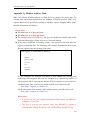
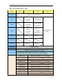
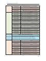
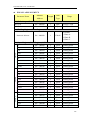
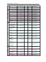
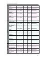
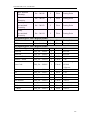
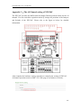
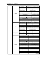
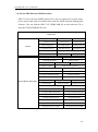
Appendix I:Modbus Address Table ................................................................ 180
Appendix II:Reset to Factory Default Setting and send password to Administrator ...... 251
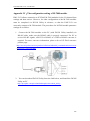
Appendix III:Setup the GTM-201-USB with PMC-5151 .................................. 254
Appendix IV:The configuration setting of M-7000 module .............................. 258
Appendix V:The AI Channel setting of XW310C ............................................ 262
Appendix VI:The SNMP Variables for PMC-5151........................................... 263
ICP DAS PMC-5151 User Manual
List of Figures
Figure1-1 :
Figure3-1 :
Figure4-1 :
Figure4-2 :
Figure4-3 :
Figure4-4 :
PMC-5151 System Architecture...................................................... 1
PMC-5151 Login page .................................................................. 5
PMC-5151 Main Page ................................................................... 6
System Function Area (login as a Administrator) .............................. 7
System Function Area(login as a General user) ................................ 7
Rules management toolbar (login as a Administrator) ....................... 7
Figure4-5 :
Figure4-6 :
Figure4-7 :
Figure4-8 :
Figure4-9 :
Figure4-10 :
Figure4-11 :
Figure4-12 :
Figure4-13 :
Rules management toolbar (login as a General user) ......................... 8
Confirm to clear settings ................................................................ 8
Confirm to load settings ................................................................. 8
Confirm to save settings................................................................. 9
Confirm to logout (The settings are saved) ....................................... 9
Confirm to logout (The settings are not saved) ................................. 9
Real-time information area ........................................................... 10
Real-time information list ............................................................ 10
Current function path ................................................................... 11
Figure4-14 :
Figure4-15 :
Figure4-16 :
Figure5-1 :
Figure5-2 :
Figure5-3 :
Figure5-4 :
Figure5-5 :
Figure5-6 :
Power data Overview page ........................................................... 12
Select the classification of Power data ........................................... 12
Display power data of the selected classification ............................ 13
Information display options on Main Page ..................................... 14
Power Meter Information Overview .............................................. 15
The attribute of PM-3133 Power Meter ......................................... 15
The attribute of PM-3133-MTCP Power Meter............................... 16
Real Time Power Information of PM-3133 .................................... 16
Real Time Power Information of PM-3114 .................................... 17
Figure5-7 :
Figure5-8 :
Figure5-9 :
Figure5-10 :
Figure5-11 :
Figure5-12 :
Figure5-13 :
Figure5-14 :
Real Time Power Information of PM-3112 .................................... 17
Power Meter Statistics Information ............................................... 18
Power Data Overview Mode ........................................................ 20
Change Display List Button ......................................................... 21
The Power Meter List .................................................................. 21
Power Data Group Overview Mode .............................................. 21
Realtime Chart (Power Meter Mode) ............................................. 23
Realtime Chart (Group Mode) ...................................................... 25
Figure5-15 :
Historical Chart Inquiry ............................................................... 26
Figure5-16 :
Figure5-17 :
Historical Data Chart for power data ............................................. 27
Historical Data Table for power data ............................................. 28
ICP DAS PMC-5151 User Manual
Figure5-18 :
Figure5-19 :
Figure5-20 :
Figure5-21 :
Figure5-22 :
Figure5-23 :
Figure5-24 :
Figure5-25 :
Figure5-26 :
Historical Data Report inquiry ...................................................... 28
Daily Report for PM-3133 ........................................................... 29
Daily Report for PM-3114 ........................................................... 30
Electricity Usage Analysis of Trend .............................................. 31
Inquiry by Group Mode ............................................................... 32
Inquiry by User-defined Mode ...................................................... 32
PM-3114 Electricity Usage Analysis Trend Chart ........................... 33
Electricity Usage Analysis of Time ............................................... 34
Time Histogram Chart for PM-3114 Loop 1 ................................... 35
Figure5-27 :
Figure5-28 :
Figure5-29 :
Figure5-30 :
Figure5-31 :
Figure5-32 :
Figure5-33 :
Figure5-34 :
Figure5-35 :
Electricity Usage Analysis of Proportion ....................................... 36
Inquiry by Group Mode ............................................................... 37
Inquiry by User-defined Mode ...................................................... 37
Electricity Usage Analysis of Proportion Chart ............................... 38
PUE information - Realtime ......................................................... 39
PUE information - History(1) ....................................................... 40
PUE information - History(2) ....................................................... 40
I/O Information(login as Administrator) ........................................ 41
I/O Information(login as General User) ......................................... 41
Figure5-36 :
Figure5-37 :
Figure5-38 :
Figure5-39 :
Figure5-40 :
Figure6-1 :
Figure6-2 :
Figure6-3 :
Figure6-4 :
Event Log information display ..................................................... 42
User-Defiend HMI page............................................................... 43
Polling Time Information ............................................................. 44
The User Interface of Modbus Table Information ........................... 45
Inquiry result of Modbus Table Information ................................... 45
System Setting Overview Page ..................................................... 47
Time Setting Page ....................................................................... 48
Time Synchronization Setting ....................................................... 49
Network Setting Page .................................................................. 50
Figure6-5 :
Figure6-6 :
Figure6-7 :
Figure6-8 :
Figure6-9 :
Figure6-10 :
Figure6-11 :
Figure6-12 :
Setting interface of VPN function ................................................. 51
Setting interface of VPN function ................................................. 52
Security setting interface of VPN function ..................................... 53
SNMP Setting Page ..................................................................... 54
SNMP Manager List .................................................................... 55
The Address Setting for SNMP Manager ....................................... 55
The Working Model Setting for SNMP Manager ............................ 55
Save the SNMP Manager Setting .................................................. 56
Figure6-13 :
Security Setting Page ................................................................... 57
Figure6-14 :
Figure6-15 :
Password Setting Page ................................................................. 58
Local FTP Server Setting Page ..................................................... 58
ICP DAS PMC-5151 User Manual
Figure6-16 :
Figure6-17 :
Figure6-18 :
Figure6-19 :
Figure6-20 :
Figure6-21 :
Figure6-22 :
Figure6-23 :
Figure6-24 :
Idle Time Setting Page ................................................................. 59
I/O Interface Setting Page ............................................................ 59
Function setting to connect to HMI or SCADA .............................. 60
Function setting to connect to Modbus RTU slave device ................ 60
I/O Function setting about LAN.................................................... 61
Other setting page ....................................................................... 62
Power Meter Group Setting .......................................................... 63
Group and Subgroup Viewing ...................................................... 63
Group Setting ............................................................................. 64
Figure6-25 :
Figure6-26 :
Figure6-27 :
Figure6-28 :
Figure6-29 :
Figure6-30 :
Figure6-31 :
Figure6-32 :
Figure6-33 :
Subgroup Setting ........................................................................ 64
Subgroup Setting Window ........................................................... 64
Configurations for Subgroup ........................................................ 65
Loops/Phases of subroup Setting .................................................. 66
Choose Loops/Phased of Subgroup ............................................... 66
Add Loops/Phases for Subgroup ................................................... 67
Configurations for Loops/Phased of Subgroup ............................... 67
Firmware Update(1) .................................................................... 68
Firmware Update(2) .................................................................... 69
Figure6-34 :
Figure6-35 :
Figure6-36 :
Figure6-37 :
Figure7-1 :
Figure7-2 :
Figure7-3 :
Figure7-4 :
Figure7-5 :
Firmware Update(3) .................................................................... 69
Firmware Update(4) .................................................................... 69
Firmware Update(5) .................................................................... 70
Firmware Update(6) .................................................................... 70
Meter / Module Setting Page ........................................................ 71
Power Meter Setting Page ............................................................ 72
The “Scan” button to search Power Meter ...................................... 73
Set up the Scanning Range for the Power Meters ............................ 73
Scaning the Power Meters ............................................................ 74
Figure7-6 :
Figure7-7 :
Figure7-8 :
Figure7-9 :
Figure7-10 :
Figure7-11 :
Figure7-12 :
Figure7-13 :
The Power Meter List after Scan operation .................................... 74
Select the actual Power Meter connected to PMC-5151 ................... 74
Set up the No and Address of the power meter ............................... 75
Select Modbus RTU Power Meter model ....................................... 75
Add the Modbus RTU Power Meter mannually .............................. 76
Add Modbus TCP Power Meter .................................................... 76
Select Modbus TCP Power Meter model........................................ 76
Add the Modbus TCP Power Meter mannually ............................... 77
Figure7-14 :
Power Meter List Interface ........................................................... 77
Figure7-15 :
Figure7-16 :
PM-3133 Setting Page ................................................................. 78
PM-3114 Setting Page ................................................................. 80
ICP DAS PMC-5151 User Manual
Figure7-17 :
Figure7-18 :
Figure7-19 :
Figure7-20 :
Figure7-21 :
Figure7-22 :
Figure7-23 :
Figure7-24 :
Figure7-25 :
PM-3114-MTCP Setting Page ...................................................... 81
XW-Board Setting Page ............................................................... 83
XW-Board DI attribute setting page .............................................. 84
XW-Board DO attribute setting page ............................................. 85
XW-Board AI attribute setting page .............................................. 86
AI Deadband Operation(> or >= a numerical value)........................ 87
AI Deadband Operation(< or <= a numerical value)........................ 88
AI Deadband Operation(= a numerical value) ................................ 88
XW-Board AO attribute setting page ............................................. 89
Figure7-26 :
Figure7-27 :
Figure7-28 :
Figure7-29 :
Figure7-30 :
Figure7-31 :
Figure7-32 :
Figure7-33 :
Figure7-34 :
I/O Module Setting Page .............................................................. 90
The “Scan” button to search M-7000 module ................................. 91
Set up the Scanning Range for the M-7000 module......................... 91
Scaning the M-7000 modules ....................................................... 92
The M-7000 List after Scan operation ........................................... 92
Select the actual M-7000 modules connected to PMC-5151 ............. 92
Set up the No and Address of the Modbus RTU module .................. 93
Select the model of the Modbus RTU Module ................................ 93
Add the Modbus RTU Module mannually...................................... 94
Figure7-35 :
Figure7-36 :
Figure7-37 :
Figure7-38 :
Figure7-39 :
Figure7-40 :
Figure7-41 :
Figure7-42 :
Figure7-43 :
Add Modbus TCP Module ........................................................... 94
Add the Modbus RTU Power Meter mannually .............................. 95
Modbus module List Interface ...................................................... 95
M-7000 DI Channel Setting Page.................................................. 97
M-7000 DO Channel Setting Page ................................................ 98
M-7000 AI Channel Setting Page .................................................. 99
M-7000 AO Channel Setting Page .............................................. 100
Modbus RTU Slave Module Setting Page .................................... 101
Coil Output Setting Page............................................................ 103
Figure7-44 :
Figure7-45 :
Figure7-46 :
Figure7-47 :
Figure7-48 :
Figure7-49 :
Figure7-50 :
Figure7-51 :
Coil Output Setting Example for Modbus RTU Module ................ 104
Discrete Input Setting Page ........................................................ 105
Discrete Input Setting Example for Modbus RTU Module ............. 106
Input Register Setting Page ........................................................ 107
Input Register Setting Example for Modbus RTU Module ............. 109
Holding Register Setting Page .................................................... 110
Input Register Setting Example for Modbus RTU Module ............. 112
Modbus TCP Slave Module Setting Page(1)................................. 113
Figure7-52 :
Modbus TCP Slave Module Setting Page(2)................................. 114
Figure8-1 :
Figure8-2 :
Data Logger Setting Page........................................................... 115
Data Logger Setting Page........................................................... 116
ICP DAS PMC-5151 User Manual
Figure8-3 :
Figure8-4 :
Figure9-1 :
Figure9-2 :
Figure9-3 :
Figure9-4 :
Figure9-5 :
Figure9-6 :
Figure9-7 :
Event Logger Setting Page ......................................................... 119
FTP Upload Setting Page ........................................................... 119
Email setting page ..................................................................... 129
Email setting page(Name & Description)) ................................... 130
Email setting page(SMTP Server) ............................................... 130
Email setting page(Email Address) ............................................. 131
Email setting page(Email Content) .............................................. 131
SMS Setting Page (1) ................................................................ 133
SMS Setting Page (2) ................................................................ 133
Figure9-8 :
Figure9-9 :
Figure9-10 :
Figure9-11 :
Figure9-12 :
Figure9-13 :
Figure9-14 :
Figure9-15 :
Figure9-16 :
SMS Command Setting Page (1)) ............................................... 135
SMS Command Setting for GET Command ................................. 136
SMS Command Setting for SET Command ................................. 137
SMS Command list ................................................................... 137
SNMP Trap Setting Page ........................................................... 139
SNMP Trap Parameter Setting Page ............................................ 139
“Channel Data”Type Setting Page ............................................... 140
Example of “Channel Data” Type Variable Binding List ................ 141
“User-Defined Data” Type Setting Page ...................................... 141
Figure9-17 :
Figure9-18 :
Figure9-19 :
Figure9-20 :
Figure9-21 :
Figure9-22 :
Figure9-23 :
Figure9-24 :
Figure9-25 :
“User-Defined Data” Interface in Edit Mode ................................ 142
“User-Defined Data” Interface in View Mode .............................. 143
SNMP Trap setting with variable bindings list .............................. 143
Timer creating Page................................................................... 145
Timer setting Page(Assign Period) .............................................. 145
Timer setting page(Internal Register) .......................................... 145
Schedule setting page ................................................................ 146
Calendar mode of Schedule setting ............................................. 147
Repeat mode of Schedule setting ................................................ 148
Figure9-26 :
Figure9-27 :
Figure9-28 :
Figure9-29 :
Figure10-1 :
Figure10-2 :
Figure10-3 :
Figure10-4 :
PUE Setting Page(1).................................................................. 149
PUE Setting Page(2).................................................................. 150
Internal Register setting page(1) ................................................. 151
Internal Register setting page(2) ................................................. 151
Rules overview page ................................................................. 153
Rules setting page ..................................................................... 154
DI condition setting page ........................................................... 156
DI Counter condition setting page ............................................... 157
Figure10-5 :
AI condition setting page ........................................................... 158
Figure10-6 :
Figure10-7 :
Discrete Input condition setting page ........................................... 160
Coil Output condition setting page .............................................. 161
ICP DAS PMC-5151 User Manual
Figure10-8 :
Figure10-9 :
Figure10-10 :
Figure10-11 :
Figure10-12 :
Figure10-13 :
Figure10-14 :
Figure10-15 :
Figure10-16 :
Input Register condition setting page ........................................... 161
Holding Register condition setting page ...................................... 162
Power Meter condition setting page ............................................ 163
Connection Status condition setting page ..................................... 164
Timer condition setting page ...................................................... 164
Schedule condition setting page .................................................. 165
FTP Upload Status condition setting page .................................... 165
SD Card Status condition setting page ......................................... 166
Rule Status condition setting page............................................... 166
Figure10-17 :
Figure10-18 :
Figure10-19 :
Figure10-20 :
Figure10-21 :
Figure10-22 :
Figure10-23 :
Figure10-24 :
Figure10-25 :
Internal register condition setting page ........................................ 167
DI Counter action setting page ................................................... 169
DO action setting page............................................................... 169
AO action setting page............................................................... 170
Coil Output action setting page ................................................... 172
Holding Register action setting page ........................................... 173
Power Meter Relay Action setting page ....................................... 174
Timer action setting page ........................................................... 174
Email action setting page ........................................................... 175
Figure10-26 :
Figure10-27 :
Figure10-28 :
Figure10-29 :
Figure10-30 :
SMS Alarm action setting page ................................................... 175
SNMP Trap Action Setting Page ................................................. 177
Data Logger action setting page .................................................. 178
Rule Status action setting page ................................................... 178
Internal Register action setting page ............................................ 179
ICP DAS PMC-5151 User Manual
1
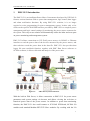
PMC-5151 Introduction
The PMC-5151 is an intelligent Power Meter Concentrator developed by ICP DAS. It
features various functions such as: power data management, logic control, data logger
and alarm notification functions. By using PMC-5151 solution; it is no longer
required to write programming for power management system. It takes only a few
clicks on the specific Web HMI Interface provided by PMC-5151 to complete power
management and logic control settings for monitoring the power meters connected to
the system. This easy-to-use solution will dramatically reduce the labor and cost spent
on power monitoring and management system.
PMC-5151 allows connections to ICP DAS power meters via RS-485 or Ethernet
interface to read the power data of the devices measured by the power meters; and
then real-time record the power data in the data file. PMC-5151 also provides data
logger file auto send-back function; together with PMC Data Server software or
SCADA software, it allows collection and analysis of the power data.
Figure1-1 :
PMC-5151 System Architecture
With the built-in Web Server, it allows connection to PMC-5151 for power meter
parameters and system settings via browser and allows viewing the real time or
historical power data of the power meters. In addition to power data monitoring
function, the PMC-5151 also could connect to ICP DAS XW-Board, M-7000 I/O
modules and standard Modbus RTU/TCP Slave modules. By working with the I/O
1
ICP DAS PMC-5151 User Manual
modules, and functions such as IF-THEN-ELSE logic rule execution and Email/SMS
Alarm Notification, PMC-5151 offers more thought-out power demand management
and alarm notification functions, and is able to perform load shedding of the devices if
required, and enables real-time monitoring and control of the power consumption of
the devices. At the same time, with the Data Logger function on microSD card, the
PMC-5151 could real-time record the power data and I/O channel data, and
automatically sends back the data file to management center for further statistics and
analysis.
In addition to the standard power data review page, by using the Flash HMI web page
editor function on PMC-5151, the users could easily design a specific power
monitoring page by a few clicks on browsers. PMC-5151 also offers Modbus
TCP/RTU Slave function that allows SCADA software or HMI devices to connect to
PMC-5151 to get real-time power data of the devices via Modbus TCP/RTU protocol.
When using PMC-5151 to build a power management and monitoring system, during
the whole process of system development, no programming is required; it takes a few
clicks on web page to complete all settings; it is easy for the user to quickly view the
power data of the devices and furthermore process the data for statistics and analysis.
The PMC-5151 is an easy-to-use and easy-to-build total solution for power
management and monitoring that makes more efficient energy usage.
PMC-5151 features:
Web-Based Operation
No extra software tool is required; all operations can be done through the
Web browsers to build a power monitoring & management solution.
Built-in Web Server allows to set up the parameters of the power meters
and view power data via browsers.
Power Data Display
Support ICP DAS Modbus TCP/RTU power meters.
Display real-time or historical power data (in data table or chart form).
Provides Daily and Monthly power data report.
Offer Flash HMI Tools for easy HMI Web interface design.
Power Data Log
Provides real-time power data log of the power meters (in csv format).
Automatically send back power data files at scheduled time via FTP.
Allow to recover Data Log files when the network is resumed after
temporary network disconnection.
2
ICP DAS PMC-5151 User Manual
Together with PMC Data Server software, it allows to import the content
of the power data files into the Database system.
Power Demand Management and Alarm Notification
With built-in IF-THEN-ELSE logic engine that enables thought-out power
demand management functions.
Support ICP DAS XW-Board, M-7000 I/O modules and standard Modbus
RTU/TCP Slave modules for real-time I/O control and monitoring.
Provides Schedule function for device operation control.
Provides alarm message notification function via Email or SMS (for SMS
message sending, GTM-201-USB is required).
Others
Support Modbus TCP/RTU Slave protocol that allows seamless integration
with SCADA software.
Offers access management for logic rule settings and encoded function for
the content to avoid unauthorized access to the system.
This document is intended to give you a full-range instruction to PMC-5151. You will
be able to learn how to connect to power meters and I/O modules, how to display and
log the power data, how to edit logic of the rules and how to download the rules to the
PMC-5151 for conditional execution.
3
ICP DAS PMC-5151 User Manual
2
Before Installation
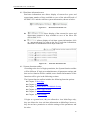
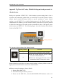
Modify PMC-5151‘s network settings to fit current network environment settings, and
the default network settings of PMC-5151 is as follow:
IP:192.168.255.1
Subnet mask:255.255.0.0
Gateway address:192.168.0.1
DNS Server address:8.8.8.8 (default: Google DNS Server)
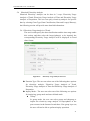
Steps
(1) Modify the network settings of the PC or Notebook to be the same network
segment as PMC-5151. For example:
IP:192.168.255.10
Subnet mask:255.255.0.0
Gateway address:192.168.0.1
(2) Connect PMC-5151 LAN1 to PC by network cable. (PMC-5151 is capable of
auto-crossover)
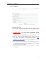
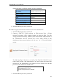
(3)Start the browser and input http://192.168.255.1 in the address bar.
(4)Input default administrator password “Admin” to login into the page.
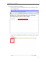
(5) After login in PMC-5151 web page, go to System Setting Network Setting,
modify the network setting to fit current network environment. More detailed
setting information please refer to 6.2 Network Setting.
(6) Save the settings and connect PMC-5151 to the network.
Please Note:
1. Before installing PMC-5151, please finish the hardware installation of the
ICP DAS Power meter modules, and make sure all wiring connections are
accurate.
2. If there are the M-7000 modules or Modbus TCP/RTU Slave modules which
will connect with PMC-5151, please also finish the hardware installation of
the M-7000 modules or Modbus TCP/RTU Slave modules, and make sure all
wiring connections are accurate.
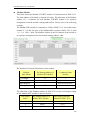
3. One PMC-5151 allows connections to at most 24 ICP DAS Modbus power
meters (including Modbus RTU and Modbus TCP power meters.).
4. One PMC-5151 allows connections to at most 8 Modbus TCP/RTU Slave I/O
modules.
5. A single I/O interface (COM2, COM3 or LAN) allows connections to at most
16 devices (Power meters and I/O modules).
4
ICP DAS PMC-5151 User Manual
3
System Login
When connect to PMC-5151 webpage server via Web browser (IE 8 / Firefox 3.6 /
Chrome 14.0.8 version or above are recommended), in order to get a better operation
experience, 1280x1024 resolution is recommended. The Login page of PMC-5151 is
shown as below:
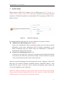
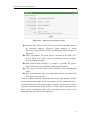
Figure3-1 :
PMC-5151 Login page
By inputing different passwards, two levels of authority are granted as follow:
Administrator (Default password: Admin)
Login as an administrator allows performing settings and reviewing of system
information, power meter information and I/O modules information, it also
allows performing Logic rule edition. Only one administrator is allowded to
login into the system at the same time.
General User (Default password: User)
General users are allowed to view power meter data and I/O module information
only; they are not allowed to perform any settings. It allows maximum 5 general
users to login and get into the system at the same time.
Select your preferred language from the dropdown list in the “Language” field for the
Web page user interface (English, Traditional Chinese, Simplified Chinese). After
login into the system, if the user want to change the language again, logout and
re-select the language on the Login page.
Please note: Before starting the system, please make sure the browser you are using
already enable JavaScript support and has the latest version of Adobe Flash Player
installed, otherwise the system will not function properly.
5
ICP DAS PMC-5151 User Manual
4
System Main Page
After login into the system, PMC-5151 default home page will be displayed, and will
automatically read settings of the PMC-5151 to the webpage.
A
B
C
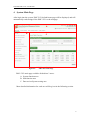
Figure4-1 :
PMC-5151 Main Page
PMC-5151 main page could be divided into 3 areas:
A. System function area
B. Sub-function area
C. Data review/System setting area
More detailed information for each area will be given in the following section.
6
ICP DAS PMC-5151 User Manual
4.1
System function area
System function area provides immediately access to the main functions of
PMC-5151, such as: system settings, system real-time information display,
rule files management, etc, shown as below:
A1
A3
A2
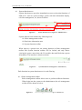
Figure4-2 :
System Function Area (login as a Administrator)
System function area includes the following areas:
A1. Rules management toolbar
A2. Real-time information area
A3. System function toolbar
When login as a general user, the setting functions in Rules management
toolbar and System function toolbar will be locked, and only allows
viewing the power meter data, the I/O module data and Real-time system
information. The interface is shown as below:
Figure4-3 :
System Function Area(login as a General user)
Each function in system function area is as the flowing:
4.1.1 Rules management toolbar
Rules management toolbar allows user to perform different functions.
When login into the system as the administrator, the rule management
toolbar will be shown as below:
Figure4-4 :
Rules management toolbar (login as a Administrator)
7
ICP DAS PMC-5151 User Manual
If login as a general user, the rule management toolbar will be shown
as below:
Figure4-5 :
Rules management toolbar (login as a General user)
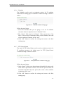
The functions of the Rules management toolbar are as follow:
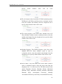
“New” button allows resetting the settings of all parameters
and Rules. Click on
button and click on “OK”, the settings on
PMC-5151 webpage on the browser will be cleared. If the user
would like to clear the setting on PMC-5151, then continue to click
on
“Save” button to save the new settings (cleared settings)
to the PMC-5151.
Please note: once the settings are cleared and save to the
PMC-5151, the settings will be cleared permanently.
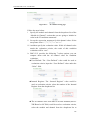
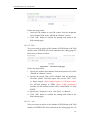
Figure4-6 :
Confirm to clear settings
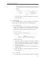
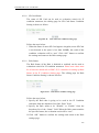
“Load” button allows to load all parameter settings and rule
settings on PMC-5151. Click on
button and click “OK” to
load all parameter settigns and rules settings from PMC-5151 to
the web page for further edition.
Figure4-7 :
Confirm to load settings
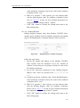
“Save” button allows to save all parameter settings and Rule
settings to PMC-5151. Click on
button and click “OK” to
save all parameter settings and Rule settings from the web page of
PMC-5151 to the PMC-5151.
8
ICP DAS PMC-5151 User Manual
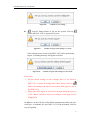
Figure4-8 :
Confirm to save settings
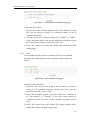
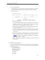
“Logout” button allows to log out the system, click on
button and click “OK” to logout the system.
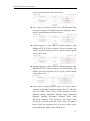
Figure4-9 :
Confirm to logout (The settings are saved)
If the settings are not saved to the PMC-5151 before performing
logout, a warming message will appear as below:
Figure4-10 :
Confirm to logout (The settings are not saved)
Please note:
1. All the edited settings on the webpage have to be saved to
PMC-5151 to make all settings take effect; before click on
button, the settings will only be saved on the Web page site, not in
the PMC-5151.
2. Please DO NOT logout or close the web page during the process
of the edition, otherwise all pre-set settings on the page will be
disappeared.
In addition, on the left side of the Rules management toolbar, the user
could give a nickname for this PMC-5151 in the nickname field for
easy recognition.
9
ICP DAS PMC-5151 User Manual
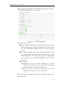
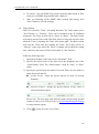
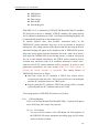
4.1.2 Real-time information area
Real-time information area allows display of current free space and
approximate number of days available to save of the microSD card of
the PMC-5151 and the real-time system information, shown as below:
Figure4-11 :
Real-time information area
Allows display of the current free space and
approxmiate number of days available to save of the micro SD
card in PMC-5151.
Allows display of real-time system information, click
on “Instant Message”to open up the list of real-time information,
maximum 10 information will be kept on the list.
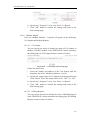
Figure4-12 :
Real-time information list
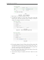
4.1.3 System function toolbar
According to the level of login permission, the System function toolbar
will be different. If login as an administrator, all parameter settings and
data review function will be enabled; more detailed information of the
functions will be give in the following sections.
The System function toolbar includes the following function options:
Chapter 5: Main Page
Chapter 6: System Setting
Chapter 7: Power Meter/ I/O Module Setting
Chapter 8: Data Logger Setting
Chapter 9: Advanced Setting
Chapter 10: Rule Setting
If login as a general user, they are allowed to view Main Page only;
they are allowed to view real-time information on Main Page, however,
they do not have permission to edit the settings of the parameters and
the rules.
10
ICP DAS PMC-5151 User Manual
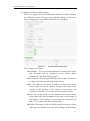
4.2
Sub-function area
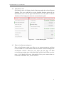
Sub-function area will display detailed functions under the selected System
function. The user could edit or review detailed function options in the
Sub-function area. On the upper Sub-function area, the path of current
function will be displayed to show the current function path.
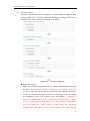
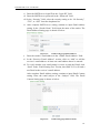
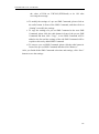
Figure4-13 :
4.3
Current function path
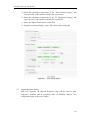
Data review/System setting area
Data review/System setting area allows to set system parameters and data
review of PMC-5151, the content of this area will be varied according to the
sub-function selected. When the user login into the page, the Data
review/System setting Area of the Main Page will be Power Data overview
page, it will display all power information of the power meters that are
connected to the PMC-5151, shown as below:
11
ICP DAS PMC-5151 User Manual
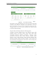
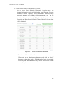
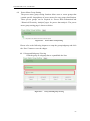
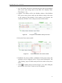
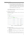
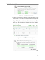
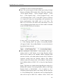
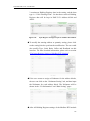
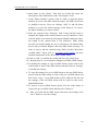
Figure4-14 :
Power data Overview page
Power data overview page display the power data of the power meters that
connected to the PMC-5151. Depend on the requirement to select the
desired classification of the power data to display the desired power data.
The page refreshes every 20 sec, the user could also click “Refresh” button
to refresh the data immediately.
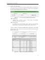
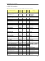
The power data classification includes the following options:
V(Voltage), I(Current), kW(Real Power), kvar (Reactive Power), kVA
(Apparent Power), PF (Power Factor), kWh, kvarh, kVAh, Daily
Accumulated Electricity, Monthly Accumulated
Electricity, Yearly
Accumulated Electricity, Daily Carbon Emissions, Monthly Carbon
Emissions, Yearly Carbon Emissions, Hourly Maximum Demand, Daily
Maximum Demand, Monthly Maximum Demand, Actual Demand and
Forecast Demand. The displayed power data will be varied according to the
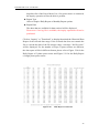
selected power data classification.
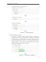
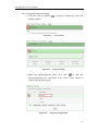
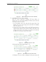
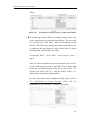
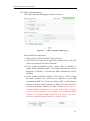
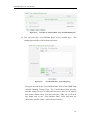
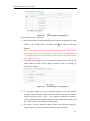
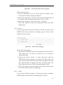
Figure4-15 :
Select the classification of Power data
12
ICP DAS PMC-5151 User Manual
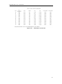
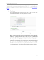
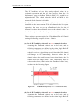
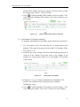
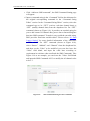
Figure4-16 :
Display power data of the selected classification
“Connection Status” will reveal the connection status between the
power meter and PMC-5151, the graphic indicators are as follow:
: Online
: Offline
: Connecting
13
ICP DAS PMC-5151 User Manual
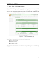
5
Main Page
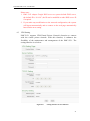
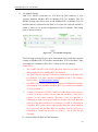
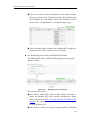
On the Main Page, 10 information display options are as follow: Power Meter
Information, Power Data Information, Realtime Chart, Historical Chart, Historical
Data Report, Historical Electricity Analysis, PUE Information, I/O Information, Event
Log, Polling Time Information, Modbus Table Information and UID information,
shown as follow:
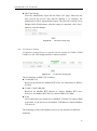
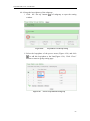
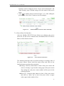
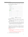
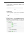
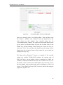
Figure5-1 :
5.1
Information display options on Main Page
Power Meter Information
Power Meter Information page displays detailed power data information
including: Power Meter Information Overview and Power Meter Statistics
Information Overview.
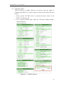
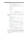
5.1.1 Power Meter Information Overview
After getting into this page, the system will display real-time power
information of the selected power meter. To display desired power
meter data information, select the power meter from the dropdown list
of the “Power Meter List”. The page refreshes every 20 seconds, the
user could also click “Refresh” button to refresh the data immediately.
Power Meter Information Overview includes the following sections:
14
ICP DAS PMC-5151 User Manual
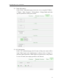
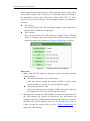
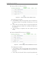
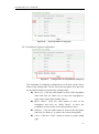
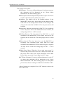
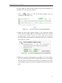
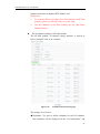
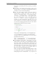
Figure5-2 :
Power Meter Information Overview
Power Meter Attribute
The Power Meter Attribute section will display different information
according to different power meters and the ways they are connected
to the PMC-5151. Currently PMC-5151 supports connecting to
power meter via Modbus RTU (Figure 5-3) or Modbus TCP(Figure
5-4). If the power meter is connected via Modbus RTU, it will
display the Power Meter Number (No.), Com Port, Address, Module
Name. If the power meter is connected via Modbus TCP, it will
display the Power Meter Number (No.), IP, Port, NetID, Module
Name.
Figure5-3 :
The attribute of PM-3133 Power Meter
15
ICP DAS PMC-5151 User Manual
Figure5-4 :
The attribute of PM-3133-MTCP Power Meter
Real Time Power Information
In this section, it provides real time power data information of the
selected Power Meter. For 3 phase power meter, it will display real
time information of Phase A, Phase B and Phase C(Figure 5-5).For
single phase power meter, it will display real time information of
Loop 1, Loop2, Loop3, and Loop4(Figure 5-6). For PM-3112 will
display real time information of Loop 1 and Loop2 (Figure 5-7).
Figure5-5 :
Real Time Power Information of PM-3133
16
ICP DAS PMC-5151 User Manual
Figure5-6 :
Real Time Power Information of PM-3114
Figure5-7 :
Real Time Power Information of PM-3112
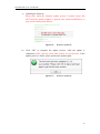
Reset Accumulated Value of the Power Meter
When login as the Administrator, it allows to click on “Reset” to
reset the value of kWh, kvarh, and kVAh to be 0 if required.
Please Note: After performing the reset function to reset the value of
the kWh, kvarh, and kVAh of the selected power meter, the resetting
operation is irreversible.
17
ICP DAS PMC-5151 User Manual
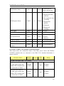
5.1.2 Power Meter Statistics Information Overview
On the Power Meter Statistics Information Overview page, the
Demand Information section will display the Actual Demand, Forecast
Demand, Contract Capacity, Hourly Maximum Demand, Daily
Maximum Demand and Monthly Maximum Demand, etc. In the
Statistics Information section, the Daily/Monthly/Yearly Accumulated
Electricity and Daily/Monthly/Yearly Carbon Emissions for each loop
will be displayed.
Figure5-8 :
Power Meter Statistics Information
Reset Power Meter Statistics information
When login as an administrator; the user could click on “Reset”
button to set the values such as: Daily/Monthly/Yearly Accumulated
Electricity and Daily/Monthly/Yearly Carbon Emissions to default
values if required.
18
ICP DAS PMC-5151 User Manual
5.1.3 Other Information
In the "Other" information page, users can view or setup the PT Ratio、
CT Ratio、Phase Sequence、Wiring Mode、Voltage Mode and other
specific parameters of the power meter.
5.1.4 I/O Information
In the "I/O" information page, the I/O status of the power meter will be
listed. When login as the Administrator, it allows click on “Status” to
perform output operations. When login as a general user, it only allows
to view I/O status, the output operation is not allowed.
19
ICP DAS PMC-5151 User Manual
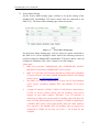
5.2
Power Data Information
Power data information can be displayed in two modes (Overview and
Group Overview), user can change the viewing mode according to the
requirements; more detailed information will be introduced in the following
sections.
5.2.1 Overview
Power Data Information overview mode allows display of power data of
different power meters at the same time. Select the classification from
the dropdown list of the Data Classification field; it will list the
requested data from various power meters for easy comparison. The page
refreshes every 20 seconds, the user could also click “Refresh” button to
refresh the data immediately.
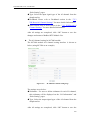
Figure5-9 :
Power Data Overview Mode
The graphic indicators next to the power meter will reveal the connection
status of the power meter, the indicators are as follow:
:Online
:Offline
:Connecting
Click on “Change display list”
(Figure 5-11) to bring up the Power
Meter List window(Figure 5-12). Select the power meter to be displayed
in the power meter list, click “OK” to complete the settings.
20
ICP DAS PMC-5151 User Manual
Figure5-10 :
Change Display List Button
Figure5-11 :
The Power Meter List
5.2.2 Group Overview
Power Data Information group overview mode allows display of power
data of pre-set group of power meters (please refer to 6.8 Power Meter
Group Setting). The page refreshes every 20 seconds, the user could also
click “Refresh” button to refresh the data immediately.
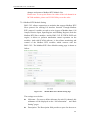
Figure5-12 :
Power Data Group Overview Mode
21
ICP DAS PMC-5151 User Manual
Select Group
Select the group from the dropdown list in the “Select Group” field. If
no group is pre-set, the inquiry operation will be disabled.
Select Subgroup
Select the subgroup from the dropdown list in the “Select Subgroup”
field. User can select one subgroup to view or select “All” to view
power datas of all subgroups.
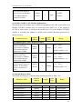
Data Classification
The power data classification includes the following options:
V(Voltage), I(Current), kW(Real Power), kvar (Reactive Power), kVA
(Apparent Power), PF (Power Factor), kWh, kvarh, kVAh, Daily
Accumulated Electricity, Monthly Accumulated Electricity, Yearly
Accumulated Electricity, Daily Carbon Emissions, Monthly Carbon
Emissions, Yearly Carbon Emissions, Hourly Maximum Demand,
Daily Maximum Demand, Monthly Maximum Demand, Actual
Demand and Forecast Demand. The displayed power data will be
varied according to the selected power data classification.
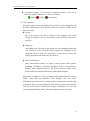
5.3
Realtime Chart
Realtime Chart allows display of power information of the power meter in
real-time trend and pie chart. Realtime Chart can be displayed in two modes
(Power Meter mode and Group mode). The users can change the viewing
mode according to their requirements. The detailed description is as follow:
5.3.1 Power Meter Mode
Select the power meter from the dropdown list of the Power Meter List
and select the classification from the dropdown list of the Data
Classification field, and then click on “Inquiry” button, it will show the
chart.
Power Meter List
All power meter connected to the PMC-5151 will be list on the
dropdown list of the Power Meter List, if no power meter is connected,
the inquiry operation will not be able to perform.
Data Classification
Data Classification allows to inquire various power data options,
including: V(Voltage), I(Current), kW(Real Power), kvar (Reactive
Power), kVA (Apparent Power), PF (Power Factor), kWh, kvarh, kVAh,
Daily Accumulated Electricity, and Actual Demand.
22
ICP DAS PMC-5151 User Manual
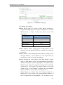
Please refer to Figure 5-14 for an example of Realtime Chart for “Power
Meter Mode”. Each time the Realtime Chart displays only one power
information classification. If a different power information classification is
inquired, previously displayed chart will be closed automatically. The user
could choose desired power data classification to view the corresponding
Realtime Chart. The chart refreshes every 5 seconds.
Figure5-13 :
Realtime Chart (Power Meter Mode)
There are three function icons on the upper area of the Power Meter
Realtime Chart:
The
icon allows to pause the update of the chart, only the data
within the 25 minutes will be displayed. The user could click and drag
on the chart and move forward or backward to show desired time zone.
Click
to resume the update of the chart. To view the data on a
specific marker, move the mouse over the marker to display the data
value.
icon allows to hide the markers on the chart; click on
show the markers on the chart.
button to
23
ICP DAS PMC-5151 User Manual
“Connection Status” will reveal the connection status of the power
meter, the graphic indicators are shown as follow:
: Online
: Offline
: Connecting
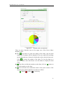
5.3.2 Group Mode
Select the option from the dropdown lists of the Group, Subgroup and
the Data Classification field, and then click on “Inquiry” button, it will
show the chart.
Group
The preset group lists will be shown on the dropdown list of the
Group, if no group is pre-set, the inquiry operation will not be able to
perform.
Subgroup
According to the selected Group option, the corresponding subgroups
will be listed. If the selected Group contains no subgroup or the
subgroup doesn’t setup any loop/phase of the power meter, the
inquiry operation will not be able to perform.
Data Classification
Data Classification allows to inquire various power data options,
including: V(Voltage), I(Current), kW(Real Power), kvar (Reactive
Power), kVA (Apparent Power), PF (Power Factor), kWh, kvarh,
kVAh, Daily Accumulated Electricity, and Actual Demand.
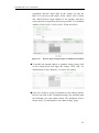
Please refer to Figure 5-15 for an example of Realtime Chart for “Group
Mode”. Each time the Realtime Chart displays only one power
information classification. If a different power information classification
is inquired, the previously displayed chart will be closed automatically.
The user could choose desired power data classification to view the
corresponding Realtime Chart. The chart refreshes every 5 seconds.
24
ICP DAS PMC-5151 User Manual
Figure5-14 :
Realtime Chart (Group Mode)
There are three function icons on the upper area of the Power Meter
Realtime Chart:
The
icon allows to pause the update of the chart, only the data
within the 25 minutes will be displayed. The user could click and drag
on the chart and move forward or backward to show desired time zone.
Click
to resume the update of the chart. To view the data on a
specific marker, move the mouse over the marker to display the data
value.
icon allows to hide the markers on the chart; click on
show the markers on the chart.
icon will show the connection status of the power meters of the
subgroup, the graphic indicators are shown as follow:
: Online
: Offline
button to
: Connecting
25
ICP DAS PMC-5151 User Manual
5.4
Historical Chart
Historical Chart allows display of the value and chart of power data in
historical trend. Select the power meter from the dropdown list of the Power
Meter List, choose the classification from the dropdown list of the Data
Classification and then specify the date from the dropdown list of the Date.
The interface is shown as below:
Figure5-15 :
Historical Chart Inquiry
Power Meter List
All power meter connected to the PMC-5151 will be list on the
dropdown list of the Power Meter List, if no power meter is connected,
the inquiry operation will not be able to perform.
Data Classification
Data Classification allows to inquire various power data options,
including: V(Voltage), I(Current), kW(Real Power), kvar (Reactive
Power), kVA (Apparent Power), PF (Power Factor), kWh, kvarh, kVAh,
Daily Accumulated Electricity, and Actual Demand.
Date
The dates that are available for power data retrieval will be displayed.
Please note, if no log file is available, the inquiry operation will not be
performed.
Click on “Inquiry” to display the power data historical statistic chart (Figure
5-17) and table (Figure 5-18) of the selected date range. If the selected date
does not contain the file or exceeds the date of the file storage range, a
message “No file exists” will be displayed. The Historical Data Chart and
Historical Data Table are shown as below:
26
ICP DAS PMC-5151 User Manual
Historical Data Chart
The historical power data of specified classification will be displayed
in historical chart. The user could select the range on the below region
or drag and move on the chart to adjust the viewing range. Move the
mouse cursor close to the marker, the value will be displayed.
Figure5-16 :
Historical Data Chart for power data
On the upper left of the Historical Chart, there are 4 function icons.
Set the Historical Chart to be default status.
Zoom in the Y-axis of the Historical Chart
Zoom out the Y-axis of the Historical Chart
Hide the markers on the Historical Chart.
markers on the Historical Chart
Show the
Historical Data Table
Historical Data Table will display the requested historical power data;
the historical power data of selected classification of each loop (or
phase) will be listed.
27
ICP DAS PMC-5151 User Manual
Figure5-17 :
Historical Data Table for power data
On the lower left of the Historical Data Table, there are 5 function
icons.
5.5
Go to the first page.
Go to previous page.
Go to specific page.
Go to next page.
Go to last page.
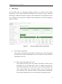
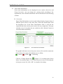
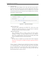
Historical Data Report
The Historical Data Report allows display of the power data report of
desired power meter; specify the power meter, power classification and date
range to inquire the data, shown as below:
Figure5-18 :
Historical Data Report inquiry
Power Meter List
All power meter connected to the PMC-5151 will be listed on the
28
ICP DAS PMC-5151 User Manual
dropdown list of the Power Meter List, if no power meter is connected,
the inquiry operation will not be able to perform.
Report Type
Allow to inquire Daily Report or Monthly Report options.
Report Date
The dates that are available for data retrieval will be displayed.
Please note: if no log file is available, the inquiry operation will not be
performed.
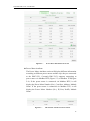
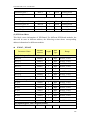
Click on “Inquiry” or ”Download” to display/download the Historical Data
Report of the selected date range. If the selected date does not contain the
file or exceeds the date of the file storage range, a message “No file exists”
will be displayed. For the number of loops of power meters are different,
the data report will be in different format, please refer to Figure 5-20 for the
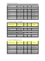
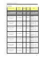
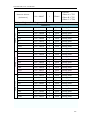
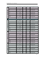
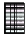
Daily Report of 3-phase power meter and Figure 5-21 for the Daily Report
of single phase power meter.
Figure5-19 :
Daily Report for PM-3133
29
ICP DAS PMC-5151 User Manual
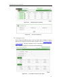
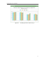
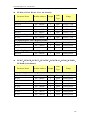
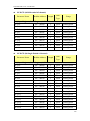
Figure5-20 :
Daily Report for PM-3114
30
ICP DAS PMC-5151 User Manual
5.6
Historical Electricity Analysis
Historical Electricity Analysis can be done in 3 ways: Electricity Usage
Analysis of Trend, Electricity Usage Analysis of Time and Electricity Usage
Analysis of Proportion. The user can query electricity analysis for specific
date by selecting Chart Type, Data Classification, Date and Loop(s)/Phase(s);
the following section will provide more detailed information:
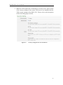
5.6.1 Electricity Usage Analysis of Trend
The users could specify the data classification and the time range under
this section, and then select the loop(s)/phase(s) to be inquired; the
corresponding Electricity Usage Analysis will be displayed in Trend
chart format.
Figure5-21 :
Electricity Usage Analysis of Trend
Function Type: The user can select one of the following three options
for electricity analysis: Electricity Usage Analysis of Trend,
Electricity Usage Analysis of Time and Electricity Usage Analysis of
Proportion.
Inquiry Mode:The user can select one of the following two options
for inquirying: group mode and user-defined mode.
Group:
In group mode, the user can select group and subgroup to
inquire the electricity usage analysis of loops/phases of the
power meters in the format of trend chart. If no group is pre-set,
the user will not be able to perform inquiry operation.
31
ICP DAS PMC-5151 User Manual
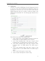
Figure5-22 :
Inquiry by Group Mode
User-defined:
In user-defined mode, all power meters connected to the
PMC-5151 will be listed. If no power meter is connected, the
user will not be able to perform inquiry operation. The
minimum loop/phase to be queried is 1 loop/phase.
Figure5-23 :
Inquiry by User-defined Mode
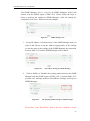
Click on “Inquiry” button to display the trend of Electricity Usage
Analysis for the specified date range. If the selected date does not
contain the file or exceeds the date of the file storage range, a message
“No file exists” will be displayed. The trend of Electricity Usage
Analysis data of specified classification will be displayed in historical
chart. The user could select the range on the below region or drag and
move on the chart to adjust the viewing range. Move the mouse cursor
close to the marker, the value will be displayed.
32
ICP DAS PMC-5151 User Manual
Figure5-24 :
PM-3114 Electricity Usage Analysis Trend Chart
On the upper left of the Electricity Usage Analysis of Trend Chart, there
are 4 function icons.
Set the Electricity Usage Analysis of Trend Chart to be
default status.
Zoom in the Y-axis of the Electricity Usage Analysis of
Trend Chart.
Zoom out the Y-axis of the Electricity Usage Analysis of
Trend Chart.
Hide the markers on the Electricity Usage Analysis of Trend
Chart.
Show the markers on the Electricity Usage Analysis
of Trend Chart.
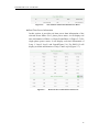
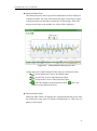
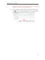
5.6.2 Electricity Usage Analysis of Time
The users could specify the data classification and the time range under
this section, and then select the loop(s)/phase(s) to be inquired; the
corresponding Electricity Usage Analysis of Time will be displayed in
histogram chart to show the annual, quarterly or monthly electricity
usage comparison for each year.
33
ICP DAS PMC-5151 User Manual
Figure5-25 :
Electricity Usage Analysis of Time
Function Type: The user can select one of the following three options
for electricity analysis: Electricity Usage Analysis of Trend,
Electricity Usage Analysis of Time and Electricity Usage Analysis of
Proportion.
Select Loop/Phase: All power meters connected to the PMC-5151
will be listed. If no power meter is connected, the user couldn’t
perform inquiry operation.
Data Classification: includes V (voltage), I (current), PF (power
factor), Electricity Usage (KWh), and Maximum Demand.
Chart Type: Provides Yearly Chart, Quarterly Chart and Monthly
Chart.
Date: Select the date range to be queried (the system will provide the
date range can be queried)
Click on “Inquiry” button to display the Electricity Usage Analysis of Time
for the specified date range. If the selected date does not contain the file or
exceeds the date of the file storage range, a message “No file exists” will be
displayed. The Electricity Usage Analysis of Time will be displayed in the
lower region in histogram chart. Move the mouse cursor close to the
histogram chart, the value will be displayed.
34
ICP DAS PMC-5151 User Manual
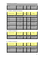
Figure5-26 :
Time Histogram Chart for PM-3114 Loop 1
35
ICP DAS PMC-5151 User Manual
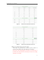
5.6.3 Electricity Usage Analysis of Proportion
The users could specify the data classification and the time range under
this section, and then select the loop(s)/phase(s) to be inquired; the
corresponding Electricity Usage Analysis of Proportion will be
displayed in category pie chart to show the Electricity Usage
Proportion of the loops/phases.
Figure5-27 :
Electricity Usage Analysis of Proportion
Function Type: The user can select one of the following three options
for electricity analysis: Electricity Usage Analysis of Trend,
Electricity Usage Analysis of Time and Electricity Usage Analysis of
Proportion.
Data Classification: includes V (voltage), I (current), PF (power
factor), Electricity Usage (KWh), and Maximum Demand.
Chart Type: Provides Yearly Chart, Monthly Chart and Daily Chart.
Date: Select the date range to be queried (the system will provide the
date range can be queried).
Inquiry Mode:The user can select one of the following two options
for inquirying: group mode and user-defined mode.
Group:
In group mode, the user can select group and subgroup to
inquiry the electricity usage analysis of loops/phases of the
power meters in the format of proportion chart. If no group is
pre-set, the user will not be able to perform inquiry operation.
36
ICP DAS PMC-5151 User Manual
Figure5-28 : Inquiry by Group Mode
User-defined:
In user-defined mode, all power meters connected to the
PMC-5151 will be listed. If no power meter is connected, the
user will not be able to perform inquiry operation. The
minimum loop/phase to be queried is 1 loop/phase.
Figure5-29 :
Inquiry by User-defined Mode
37
ICP DAS PMC-5151 User Manual
Click on “Inquiry” button to display the Electricity Usage Analysis of
Proportion for the specified date range. If the selected date does not contain
the file or exceeds the date of the file storage range, a message “No file
exists” will be displayed. The Electricity Usage Analysis of Proportion will
be displayed as category pie chart in the lower region. Move the mouse
cursor close to the category pie chart, the value will be displayed. The
electricity usage information will be listed as table below. The maximum
and minimum value of the loop/phase will be listed on the table. If the Data
Classification of the inquired data is Electricity Usage (KWh), the statistic
information of total Electricity Usage will also be listed on the table.
Figure5-30 :
Electricity Usage Analysis of Proportion Chart
38
ICP DAS PMC-5151 User Manual
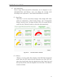
5.7
PUE Information
Power Usage Effectiveness(PUE) information can be displayed in two
modes(Real-Time and History), users can change the viewing mode
according to the requirement;more detailed information is as below:
5.7.1 Real-Time
"Real-Time" overview mode allows display of the mutiple PUE values
which are calculated by "Total Facility Energy" and "IT Equipment
Energy" preset by users. The page refreshes every 20 seconds, the user
could also click "Refresh" button to refresh the data immediately.
Figure5-31 :
PUE information - Realtime
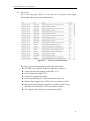
5.7.2 History
"History" overview mode allows display of the PUE data in historical
trend. Select the PUE option from the dropdown list of the PUE List,
choose the classification from the dropdown list of the Chart Type and
then specify the date from the dropdown list of the Date. The interface
is shown as below:
39
ICP DAS PMC-5151 User Manual
Figure5-32 :
PUE information - History(1)
PUE List:All PUE options which are preset by users will be listed
on the dropdown list of the PUE List, if no PUE option is preset,
the inquiry operation will not be able to perform.
Chart Type:Provides Daily Chart and Monthly Chart.
Date:The dates which are available for PUE data retrieval will be
displayed. Please note, if no log file is available, the inquiry
operation will not be performed.
Click on “Inquiry” to display the PUE data historical statistic chart
(Figure 5-34) of the selected date range. If the selected date does not
contain the file or exceeds the date of the file storage range, a message
“No file exists” will be displayed.
Figure5-33 :
PUE information - History(2)
40
ICP DAS PMC-5151 User Manual
5.8
I/O Information
The I/O Information page will display the real-time values of the Internal
Registers of the PMC-5151and the real-time I/O channels values of all I/O
modules (including XW Board, M-7000 Modules, Modbus RTU Modules
and Modbus TCP modules) that are connected to the PMC-5151. If login as
the Administrator, it allows to modify the values of Internal Registers or
output values of the DO/AO channels (Figure 5-35). If login as a general
user, they are allowed to view the values of Internal Registers and the I/O
channels (Figure 5-36) only.
Figure5-34 :
I/O Information(login as Administrator)
Figure5-35 :
I/O Information(login as General User)
The graphic indicator on the right side of the I/O modules will reveal the
connection status of the module, the graphic indicators are as follow:
: Online
: Offline
: Connecting
41
ICP DAS PMC-5151 User Manual
5.9
Event Log
The Event Log page allows to view the list of system event logger
information when login as the Administrator.
Figure5-36 :
Event Log information display
The Event Log record including the following information:
The PMC-5151 failed to read data of the power meter(s).
Change the network settings on the PMC-5151.
Save settings to the PMC-5151.
Change the system time setting.
Reset accumulated power data of the power meter to 0.
Transfer Data Logger files to FTP server succeeded or failed.
When performing firmware upgrade, record the transfer of the
firmware file to the PMC-5151 is succeeded or failed.
The upgrade of the firmware is succeeded or failed.
42
ICP DAS PMC-5151 User Manual
5.10 HMI User-Defiend HMI
User-Defined HMI will not be shown on the main page by default. When
you login as the administrator, you can set the Flash HMI project as the
default system page, and then the Flash HMI page will be shown on the
main page.
(For more detailed information about HMI project edition and settings,
please refer to Flash HMI Tools Quick Start.)
Figure5-37 :
User-Defiend HMI page
43
ICP DAS PMC-5151 User Manual
5.11 Polling Time Information
Users can check the polling time of each modules and power meters which
are connected with PMC-5151 currently. The "Polling" Time Infomation
Page" is as below:
Figure5-38 :
Polling Time Information
The graphic indicator on the right side of the No. will reveal the connection
status of the module, the graphic indicators are as follow:
: Online
: Offline
: Connecting
44
ICP DAS PMC-5151 User Manual
5.12 Modbus Table Information
The user can query and print the detailed modbus address information of
the modules which are connected to PMC-5151. Please refer to Appendix I
for more detailed Modbus address description.
Figure5-39 :
The User Interface of Modbus Table Information
Module Type
“Module Type” includes 4 options : Power Meter, I/O Module,
XW-Board, and Other Information
Module Name
According to the selected “Module Type” option, the corresponding
module name or information of “Module Name” will be listed.
Click on “Inquiry” to display the Modbus table information of the selected
module (Figure 5-39). The users can click on the "Print" button to print this
Modbus address table.
Figure5-40 :
Inquiry result of Modbus Table Information
45
ICP DAS PMC-5151 User Manual
5.13 UID Information
Users can check the UID information of each power meters which are
connected with PMC-5151 currently. The "UID Infomation" page is as
below:
Users can click "Export" button to export the UID information as CSV file.
46
ICP DAS PMC-5151 User Manual
6
System Setting
System Setting includes 6 options: Time Setting, Network Setting, SNMP Setting,
Security Setting, I/O Interface Setting and Other Setting. When you get into the
System Setting page, the system settings information of this PMC-5151 will be
displayed, as shown below:
Figure6-1 :
System Setting Overview Page
47
ICP DAS PMC-5151 User Manual
The user could view system setting information of PMC-5151 or perform firmware
update on this page. For firmware update operations, please refer to 6.9 Firmware
Update.
6.1
Time Setting
On the Time Setting page, it allows to set the time of PMC-5151 and Time
Synchronization function. The setting interface is as below:
Figure6-2 :
Time Setting Page
When get into this page, the system will read and display current time of the
PMC-5151. To modify the system time of PMC-5151, set up the date and
time on the “Time Setting page section” and then click “save” to complete
the settings. The user could click on “Load” in the “Time Duplication” to
synchronize the system time of the computer where the browser located and
the system time of the PMC-5151. The PMC-5151 also provides SNTP
Time Server function that allows to set up Time Synchronization to sync the
clock through network. The following figure illustrates the set up interface:
48
ICP DAS PMC-5151 User Manual
Figure6-3 :
Time Synchronization Setting
Follow the steps below to set up Time Synchronization Setting:
i. In the “Function Status” field, check “Enable”to enable the Time
Synchronization function.
ii. In the “SNTP Time Server” field, input the IP address or domain name of
the SNTP Time Server. There are 3 default SNTP Time Servers, the user
could modify the address to use other server. Click “Use Default SNTP
Time Servers” to restore the default Time Server settings.
iii. The default Port number setting is “123”, currently it is not allowed to be
modified.
iv. In the “Sync Interval” field, select the time interval to specify how often
will the PMC-5151 automatically connect to SNTP time server for time
synchronization through the network. The user could set the time
interval to be 6, 12, or 24 hours.
v. In the “Time Zone” field, select the time zone of the PMC-5151’s
location from the dropdown list.
vi. In the “Daylight Saving Time” field, enable the daylight saving time
function if required.
After all settings are completed, click “Save” button to save the changes.
49
ICP DAS PMC-5151 User Manual
6.2
Network Setting
Network Setting allows making a change to network configuration, web
server port or Modbus settings on the PMC-5151. The following figure
illustrates the configuration interface:
Figure6-4 :
Network Setting Page
Each time when the user enters this page, it will read and display current
network configuration (LAN1/LAN2) and port settings from the PMC-5151.
In the “Network Settings” section, the user can modify IP/Mask/
Gateway/DNS Server IP configuration. After all settings are completed,
click “Save” button to save the changes. After the network configuration is
completed, the user could login into PMC-5151 webpage via LAN1 or
LAN2, and is able to retrieve data via Modbus TCP. In the “Port Setting”
section, the user can modify the Web Server Port/ Modbus TCP Port/
Modbus NetID. After all settings are completed, click “Save” button to save
the changes.
50
ICP DAS PMC-5151 User Manual
Please note:
1. PMC-5151 adopts Google DNS server as system default DNS server,
the default IP is “8.8.8.8”, the IP can be modified to other DNS server IP
if required.
2. If you make any modification to the network configuration, the system
will logout automatically and re-connect to the web page automatically
based on the new setting.
6.3
VPN Setting
PMC-5151 supports VPN(Virtual Private Network) function to connect
with the virtual private network. With this function, it enhances the
flexibility of the maintenance and management of the PMC-5151. The
setting interface is as below:
Figure6-5 :
Setting interface of VPN function
51
ICP DAS PMC-5151 User Manual
When setting up the parameters of the VPN connection, please setup correct
and suitable settings of the VPN server, TCP/IP and security according to
the parameters of the remote VPN server. Please click "Test" or "Save"
button to test or save the settings. The description of these two buttons are
as below:
Test" button
The system will test the VPN connection settings. If the connection is
failed, please confirm the settings again.
"Save" button
The system will save the VPN connection settings. If the "Function
Status" is "Enable", the system will start the VPN connection, and the
connection status will be shown on "System Setting Page" as below:
Figure6-6 :
Setting interface of VPN function
Please note:
1. When using VPN IP address to login the system, the below functions
will be disabled:
The network settings of LAN1 and LAN2
If the user wants to modify the settings of LAN1 or LAN2, please
use the IP address of LAN1 or LAN2 to login the system.
The testing function of VPN
If the user wants to test the settings of VPN connection, please use
the IP address of LAN1 or LAN2 to login the system.
2. When the user is using the VPN IP address to login the system and save
the VPN settings, the system will logout the user and redirect the
webpage to the new VPN IP address automatically. If the user is not sure
about the new VPN IP address, please use the IP address of LAN1 or
LAN2 to login the system and go to the "System Setting Page" to
inquiry the VPN settings.
52
ICP DAS PMC-5151 User Manual
3. When the VPN connection is failed due to security issues, please check
if the security settings of the remote VPN servers are matched with the
VPN security settings of the PMC-5151. Please refer to the description
of the web setting page as below:
Figure6-7 :
Security setting interface of VPN function
53
ICP DAS PMC-5151 User Manual
6.4
SNMP Setting
The PMC-5151 provides SNMP(Simple Network Management Protocol)
V1 and V2c to work with the SNMP Network Management software for
monitoring the system data, power meter data and I/O module data.The
SNMP Setting page allows you to enable or modify the settings of the
SNMP function on the PMC-5151. The following figure illustrates the set
up interface:
Figure6-8 :
SNMP Setting Page
Please follow the steps below for the SNMP Settings:
i.
In the “Version” field, select the SNMP version that you want to use.
Currently PMC-5151 supports SNMP V2c and V1 protocol,
In the “Read Community Name” field, input a string for “Read
Community Name” for SNMP function. The default string is “public”.
iii. In the “Write Community Name” field, input a string for “Write
Community Name” for SNMP function. The default string is
“private”.
iv. In the “Trap Community Name” field, input a string for “Trap
Community Name” for the SNMP function. The default string is
“public”.
ii.
v.
In the “Contact” field, input the “Contact” string.
vi.
In the “Location” field, input the “Location” string,
54
ICP DAS PMC-5151 User Manual
The SNMP Manager List is a list for all SNMP Managers which will
interact with the SNMP Agent of PMC-5151. Please follow the steps as
below to perform the setting for SNMP Managers. After all settings are
completed, click “Save” button to save the changes.
Figure6-9 :
i.
Set up IP Address or domain name of the SNMP Manager that you
want to add. Please set up the Address appropriately, if the settings
are not the same as the settings of the SNMP Manager, the interaction
between PMC-5151 and the SNMP Manager will be failed.
Figure6-10 :
ii.
SNMP Manager List
The Address Setting for SNMP Manager
Click to Enable (or Disable) the working model between the SNMP
Manager and the SNMP Agent of PMC-5151. Currently PMC-5151
provides two working models as Read/Write (Polling) and Trap for
SNMP Manager.
Figure6-11 :
The Working Model Setting for SNMP Manager
Please Note: If no "Read/Write" field on the list is enabled to accept
55
ICP DAS PMC-5151 User Manual
the Read/Write commands, indicating that it will allow accepting the
Read/Write commands from ANY SNMP Manager.
iii.
After completing the IP address and working model setting, please
click
button to add the SNMP Manager to the list. After adding
the SNMP Manager, click “Save” button to save the changes.
Figure6-12 :
Save the SNMP Manager Setting
56
ICP DAS PMC-5151 User Manual
6.5
Security Setting
Security Setting allows user to change the password that is required when
access to PMC-5151. The user could also modify the settings of FTP Server
and Idle Time. The Security Setting page is as follow:
Figure6-13 :
Security Setting Page
Password Setting
PMC-5151 provides two passwords sets, one for Administrator, the other
for Guest. The default password for Administrator is “Admin” and “User”
for Guest. The user can modify the password in the “Password Setting”
section; the Password length is limited to 16 characters. After all settings
are completed, click “Save” button to save the changes. In addition, if
login as the Administrator, in the “Administrator Profile Setting” section,
the users could input an email address, once the password is forgotten or
lost, the PMC-5151 could send an email with the passwords
(administrator and guest) to this email address, for more detailed
57
ICP DAS PMC-5151 User Manual
information, please refer to Appendix II.
Figure6-14 :
Password Setting Page
Local FTP Server Setting
In this section, it allows to enable or disable the FTP Server function on
the PMC-5151 side. The user could connect to PMC-5151 FTP Server
via FTP software to remotely retrieve event log or data record file. To
enable this function, check “Enable” in the “Server Status” field. The
default password is “Admin”, the user could modify the password of the
FTP Server on the PMC-5151 side if required.
Figure6-15 :
Local FTP Server Setting Page
58
ICP DAS PMC-5151 User Manual
Idle Time Setting
After the administrator login into the PMC-5151 page, when the idle
time exceeds the pre-set time interval (default is 10 minutes), the
administrator will be automatically logout. The idle time could be set as
Disable/10/20/30/60 minutes, after the setting is completed, click “Save”
button to save the changes.
Figure6-16 :
6.6
Idle Time Setting Page
I/O Interface Setting
I/O Interface Setting allows to setup the function settings on COM1, COM2,
COM3 or LAN. The setting interface is shown as below:
Figure6-17 :
I/O Interface Setting Page
The I/O interface on PMC-5151 includes:
COM1(RS-232)
Reserved specifically for Modbus RTU Slave for connections to HMI or
SCADA.
COM2 / COM3 (RS-485)
Reserved for Modbus RTU Master to connect Modbus RTU slave
devices or for Modbus RTU Slave to connect HMI or SCADA.
LAN
LAN connection is by default set for Modbus TCP Slave to connect HMI
or SCADA. It can also be set for Modbus TCP Mater to connect Modbus
TCP devices.
The following section will introduce how to set I/O interface for different
functions:
59
ICP DAS PMC-5151 User Manual
Connect to HMI or SCADA via COM Port
Figure6-18 :
Function setting to connect to HMI or SCADA
The settings steps are as below:
vii. In the “Baudrate” field, select the Baudrate from the dropdown list,
the Baudrate of PMC-5151 and HMI or SCADA have to be set the
same.
viii. In the “Parity” and “Stop bits” fields, set up the Parity and Stop bits.
The Parity and Stop bits of PMC-5151 and HMI or SCADA have to
be set the same.
ix.
After all settings are completed, click “Save” button to save the
changes.
Connect to Modbus RTU slave device via COM Port.
Figure6-19 :
Function setting to connect to Modbus RTU slave device
The settings steps are as below:
i. In the “Baudrate” field, select the Baudrate from the dropdown list,
the Baudrate of PMC-5151 and Modbus RTU slave device have to be
set the same.
ii. In the “Parity” and “Stop bits” fields, set up the Parity and Stop bits.
60
ICP DAS PMC-5151 User Manual
The Parity and Stop bits of PMC-5151 and Modbus RTU slave device
have to be set the same.
iii. In the “Silent Interval” field, input the the time interval between
successive sending of commands from the PMC-5151to the Modbus
RTU slave device, the unit will be millisecond (ms).
Please Note: After the “Baudrate” is selected, the system will
automatically generate a proper value in the “Silent Interval” field.
For each Modbus RTU Slave device has different Modbus command
process capability, the response time for sending result from Modbus
RTU Slave device to PMC-5151 might be different. The user can
adjust this value to most appropriate time interval, such as: extend
this value to make sure every Modbus RTU Slave device connected to
the PMC-5151 has enough time to process the Modbus command, or
shorten this value to improve the efficiency of the poll mechanism
between Modbus RTU Slave device and PMC-5151.
iv. After all settings are completed, click “Save” button to save the
changes.
Connect to HMI (or SCADA) and Modbus TCP Slave device via LAN
Figure6-20 :
I/O Function setting about LAN
The LAN function on PMC-5151 is by default set for Modbus TCP
Slave to connect HMI or SCADA. User can also select the “Modbus
TCP Master” Checkbox to enable the Modbus TCP Mater function for
connecting to Modbus TCP Slave devices through Ethernet.
61
ICP DAS PMC-5151 User Manual
6.7
Other Setting
In the “Other Setting” section, it allows to set up Contract Capacity Setting,
Demand Interval Setting and Carbon Footprint Setting. The setting interface
is shown as below:
Figure6-21 :
Other setting page
Contract Capacity Setting
In this section, it allows to enable and set Contract Capacity. To enable
the Contract Capacity function, click on “Enable” and input the Contract
Capacity. Click “Save” button to save the settings. The Contract
Capacity being set will be displayed on the System Setting main page.
Demand Interval Setting
In this section, it allows to set Demand Interval Setting. The system will
calculate the demand according to this demand interval. The default
interval is 15 minutes; the user could set the interval to be 15/30/60
minutes. Click “Save” button to save the settings.
Carbon Footprint Setting
In this section, it allows to set Carbon Footprint Setting. Please input the
Carbon Footprint factor based on the Carbon Footprint factors for
countries worldwide that the International Energy Agency (IEA)
published.
62
ICP DAS PMC-5151 User Manual
6.8
Power Meter Group Setting
The power meter group setting function allows user to create groups that
contain specific loops/phases of power meters for easy group classification.
These pre-set groups can be inquired in “Power Data Information”and
“Historical Electricity Analysis”pages for power data analysis. The power
meter group setting page is shown as below:
Figure6-22 :
Power Meter Group Setting
Please refer to the following chapters to setup the group/subgroup and click
the “Save” button to save the chages.
6.8.1 Group and Subgroup Viewing
Click the group or subgroup bar to expand/hide the lists.
Figure6-23 :
Group and Subgroup Viewing
63
ICP DAS PMC-5151 User Manual
6.8.2 Group and Subgroup Setting
i Click the “Set up” button (
setting window.
Figure6-24 :
Figure6-25 :
) of group or subgroup to open the
Group Setting
Subgroup Setting
ii Input the group/subgroup name and click
to add this
group/subgroup to the lists(Figure 6-26). Click “Close” button to
return to group setting page.
Figure6-26 :
Subgroup Setting Window
64
ICP DAS PMC-5151 User Manual
6.8.3 Group and Subgroup configuration
Figure6-27 :
Configurations for Subgroup
The group/subgroup configurations can be done on the
Group/Subgroup Setting page. Please select the group/subgroup first
and click on the function button to perform the configurations:
Change Name:Click the radio button in front of the group
and click on “Change Name” to change the name of selected
group. Click “OK” button to save the changes.
Move Up:Click the radio button in front of the group name
and click on “Move Up” to move the group to upper order
(upper index number (No.)).
Move Down:Click the radio button in front of the group and
click on “Move Down” to move the group to lower order
(lower index number (No.)).
Copy:To copy the settings of a pre-set group to the new
group, please click the radio button in front of the pre-set
group and then click on “Copy”, a new group (in sequence)
will be added to the list and the settings of the old group will
be copied to this newly added group.
Remove:Click the radio button in front of the group and
click on “Remove” to remove the selected group.
Close:Click the “Close” button to return to group setting
page.
65
ICP DAS PMC-5151 User Manual
6.8.4 Setup the loops/phases of the subgroup
i Click the “Set up” button (
window.
Figure6-28 :
) of subgroup to open the setting
Loops/Phases of subroup Setting
ii Select the loop/phase of the power meter (Figure 6-29) and click
to add this loop/phase to the lists(Figure 6-30). Click “Close”
button to return to group setting page.
Figure6-29 :
Choose Loops/Phased of Subgroup
66
ICP DAS PMC-5151 User Manual
Figure6-30 :
Add Loops/Phases for Subgroup
6.8.5 Loop/Phase of group configuration
Figure6-31 :
Configurations for Loops/Phased of Subgroup
The loop/phase of subgroup configurations can be done on the Power
Meter Loop Setting page.. Please select the loop/phase first and click
on the function button to perform the configurations:
Move Up:Click the radio button in front of the loop/phase
name and click on “Move Up” to move the loop/phase to
upper order (upper index number (No.)).
Move Down : Click the radio button in front of the
loop/phase and click on “Move Down” to move the
loop/phase to lower order (lower index number (No.)).
Remove:Click the radio button in front of the loop/phase
and click on “Remove” to remove the selected loop/phase.
Close:Click the “Close” button to return to group setting
page.
67
ICP DAS PMC-5151 User Manual
6.9
Firmware Update
PMC-5151allows to update firmware via browser, after the update is
completed; the PMC-5151 doesn’t require to reboot. Please follow the steps
below:
i. Please contact ICP DAS service to obtain the latest version of the
PMC-5151 firmware file.
ii. Go to “System Setting” page, under the “Firmware Update Setting”,
click on “Browse”.
Figure6-32 :
Firmware Update(1)
68
ICP DAS PMC-5151 User Manual
iii. Browse through to select the new firmware file and click “Open”.
Figure6-33 :
Firmware Update(2)
iv. Click “Update” to update the firmware.
Figure6-34 :
Firmware Update(3)
v. Click “OK” to start the firmware update, to cancel the firmware update,
click “Cancel”.
Figure6-35 :
Firmware Update(4)
69
ICP DAS PMC-5151 User Manual
vi. Updating the firmware
Please note: when the firmware update process is started, please DO
NOT close the update window or perform any system modification, or
may result in unexpected failures.
Figure6-36 :
Firmware Update(5)
vii. Click “OK” to complete the update process. After the update is
completed, please clear the cache and cookies on your browser. If the
update process is failed, please perform the update again.
Figure6-37 :
Firmware Update(6)
70
ICP DAS PMC-5151 User Manual
7
Power Meter / I/O Module Setting
Meter / Module Setting page allows to perform settings of the power meters and I/O
Modules that are connected to the PMC-5151. After getting into the setting page, the
overview page will display current setting of the power meters and I/O Modules that
are connected to the PMC-5151, shown as below:
Figure7-1 :
Meter / Module Setting Page
Meter/Module Setting includes the following 3 setting options:
Power Meter Setting
XW-Board Setting
I/O Module Setting
More detailed information for each function setting will be given in the following
sections:
71
ICP DAS PMC-5151 User Manual
7.1
Power Meter Setting
On the “Power Meter Setting” page, it allows to set up the settings of the
Modbus RTU and Modbus TCP power meters that are connected to the
PMC-5151. The Power Meter Setting page is shown as below:
Figure7-2 :
Power Meter Setting Page
On the Power Meter Setting page, a list for all power meters connected to
the PMC-5151 will be displayed. Please follow the following sections to
perform settings for Modbus RTU and Modbus TCP power meters. After all
settings are completed, click “Save” button to save the changes.
Please note:
1. PMC-5151 provides COM2(RS-485) and COM3(RS-485) interface
that allows connections to Modbus RTU power meters.
2. PMC-5151 provides LAN interface that allows connections to Modbus
TCP power meters. For more detailed information about LAN settings
please refer to “6.4 I/O Interface setting”.
3. One PMC-5151 allows connections to at most 24 ICP DAS Modbus
power meters (including Modbus RTU and Modbus TCP power
meters.)
4.
A single I/O interface (COM2, COM3 or LAN) allows connections to
at most 16 devices (Power meters and I/O modules); each device
requires its own index number. Therefore, if an I/O interface is
connecting to both power meters and I/O modules, they will share the
same set of the index numbers. For example, if COM2 is connecting to
2 Modbus RTU power meters and already takes the index numbers
No.1 and No.2, the Modbus RTU I/O modules that are going to be
connected to COM2 can be only set as No.3 ~ No.16 that are not
occupied.
72
ICP DAS PMC-5151 User Manual
7.1.1 Scan to add Modbus RTU Power Meters
Perform “Scan” to automatically build a list of Modbus RTU power
meters that are connected to the PMC-5151. The steps are as below:
i Before performing the scan of the power metters, please make sure
the RS-485 wirings connecting to the PMC-5151 and the power
meters function well, and make sure the settings of the addresses of
the power meters are completed.
ii Click
to start the scan of Modbus RTU power meters that are
connected to the PMC-5151.
Figure7-3 :
The “Scan” button to search Power Meter
iii When the Scan page appears (Figure 7-4), input the starting address
and the ending address of the Modbus address that are going to
perform scan. Click on “Scan”, the system will start to scan the
power meters that match the settings previously set, to cancel the
scan, click on “Cancel”.
Figure7-4 :
Set up the Scanning Range for the Power Meters
iv When the system is performing the scan (Figure 7-5), the address
that are performing scan will be dynamically shown on the upper
left side, please wait till the scan operation is completed. To stop the
scan operation, click on “Cancel” to terminal the scan and leave the
page.
73
ICP DAS PMC-5151 User Manual
Figure7-5 :
Scaning the Power Meters
v After the Scan operation is completed, a Power Meter List will
appear (Figure 7-6). If the newly scaned module doesn’t match the
module previously set on the same address, a window will appear
(Figure 7-7), please select the actual device that are connected to
PMC-5151. After all settings are completed, click “Save” button to
save the changes.
Figure7-6 :
Figure7-7 :
The Power Meter List after Scan operation
Select the actual Power Meter connected to PMC-5151
7.1.2 Add Modbus RTU Power Meter manually
In addition to perform Scan operation to automatically add Modbus
RTU power meters to the list, the user could also add the Modbus RTU
power meter manually one by one, the steps are as below:
74
ICP DAS PMC-5151 User Manual
i No: The number will be the order that the power data of the Modbus
RTU power meter being stored in the PMC-5151 Modbus Table.
The range is 1~16.
ii Address: The address will be the Modbus address of this Modbus
RTU power meter, please make sure the address setting is the same
as the settings of the module, if the setting is not accurate, the
connection for PMC-5151 to the power meter will be failed.
Figure7-8 :
Set up the No and Address of the power meter
iii Select the Power meter model:
Figure7-9 :
Select Modbus RTU Power Meter model
iv Nickname: For user to define a nickname for this power meter, this
nickname will be displayed on the “Power meter Information” and
“Rule Setting” pages. Default setting will be the model of the power
meter.
v Click
to add the meter to the list (Figure 7-10). After adding the
power meter, click “Save” button to save the changes.
75
ICP DAS PMC-5151 User Manual
Figure7-10 :
Add the Modbus RTU Power Meter mannually
7.1.3 Add Modbus TCP Power Meter manually
PMC-5151 allows connection to Modbus TCP Power Meters via
Ethernet, the user could add the Modbus TCP Power meter to the list
manually; the steps are as below:
i No: The Number will be the order that the power data of the
Modbus TCP power meter being stored in the PMC-5151 Modbus
Table. The range is 1~16.
ii Network: Set up the settings of IP, Port and NetID appropriately as
required. Please make sure the network setting is the same as the
settings of the module, if the setting is not accurate, the connection
for PMC-5151 to the power meter will be failed.
Figure7-11 :
Add Modbus TCP Power Meter
iii Select the Power meter model (Figure 7-12):
Figure7-12 :
Select Modbus TCP Power Meter model
iv Nickname: For user to define a nickname for this power meter, this
76
ICP DAS PMC-5151 User Manual
nickname will be displayed on the “Power meter Information” and
“Rule Setting” pages. Default seting will be the model of the power
meter.
v Click
to add the meter to the list (Figure 7-13). After adding the
power meter, click “Save” button to save the changes.
Figure7-13 :
Add the Modbus TCP Power Meter mannually
7.1.4 Power Meter List Interface
After the Modbus RTU/TCP Power Meters are added to the power
meter list via auto scan or manual work, the Modbus RTU/TCP Power
Meters will be listed as below:
Figure7-14 :
Power Meter List Interface
The following functions allow to perform settings or rearrange order of
the power meters. Please select the power meter and click on the
function button to perform the operations:
Setting: Click the radio button in front of the power meter and
click on “Setting” to get into the setting page of the power meter.
The settings for each power meter module will be given in the
following section.
Move Up: Click the radio button in front of the power meter
and click on “Move Up” to move the power meter to upper
order (upper index number (No)).
77
ICP DAS PMC-5151 User Manual
Move Down: Click the radio button in front of the power meter
and click on “Move Down” to move the power meter to lower
order (lower index number (No)).
Copy: To copy the settings of a pre-set power meter to the new
power meter, please click the radio button in front of the pre-set
power meter and then click on “Copy”, a new power meter (in
sequence) will be added to the list and the settings of the old
power meter will be copied to this newly added power meter.
Remove: Click the radio button in front of the power meter and
click on “Remove” to remove the selected power meter.
After all settings are completed, click “Save” button to save the
changes.
7.1.5 Modbus RTU Powe Meter Setting
PMC-5151 support ICP DAS Single-phase and Three-phase Modbus
RTU Powe Meters, the following section will give more detailed
settings of each power meter setting page.
The Three-Phase Modbus RTU Powe Meter Setting page is shown
as follow (using PM-3133 as an example):
Figure7-15 :
PM-3133 Setting Page
78
ICP DAS PMC-5151 User Manual
The settings are as follow:
Nickname:For user to define nicknames for each power meter,
this nickname will be displayed on the “Power Meter
Information” and “Rule Setting” pages.
Description: The Description field provides a space for the user
to make a brief description of this power meter.
Address: The address will be the Modbus address of this
Modbus RTU power meter, please make sure the address setting
is the same as the settings of the module, if the setting is not
accurate, the connection for PMC-5151 to the power meter will
be failed.
Scan Rate: Input the time interval for PMC-5151 to periodically
retrieve the power data of this Modbus RTU Power Meter, the
setting range will be 0 ~ 65535 seconds.
Polling Timeout: The time interval for PMC-5151 to send
command to the Modbus RTU Power Meter and wait for the
response, the unit will be ms. The setting range will be 1-10000
ms.
Retry Interval: The time interval to wait for PMC-5151 to
repeatedly send command again when PMC-5151 sends
command to the Modbus RTU Power Meter and get no response.
The unit will be second. the setting range will be 3 ~ 65535
seconds.
Main Power Meter: When the “Set as main power meter” is
selected, this power meter will be set as main power meter and
the power data of this meter will be displayed on the Main
Power Meter area on the “Power Data Overview” page.
CT/Phase Nickname: For user to define nicknames for each CT
(or phase), this nickname will be displayed on the “Power
Meter Information” and “Rule Setting” pages. For three-phase
power meter, the user could give nicknames to the Phase A/B/C.
After all settings are completed, click “OK” button to return to the
Power Meter List.
79
ICP DAS PMC-5151 User Manual
The Single-Phase Modbus RTU Powe Meter Setting page is shown
as follow (using PM-3114 as an example):
Figure7-16 :
PM-3114 Setting Page
The settings are as follow:
For the settings of Nickname, Description, Address, Scan Rate,
Polling Timeout, Retry Interval and Main Power Meter, please
refer to “Three-Phase Modbus RTU Powe Meter Setting”
section.
CT / Phase Nickname: For user to define nicknames for each
CT (or phase), this nickname will be displayed on the “Power
Meter Information” and “Rule Setting” pages. For single-phase
power meter, the user could give nicknames to the CT1/CT2/
CT3/CT4.
DO Attribute:
Nickname:For user to define nicknames for each DO
channel, this nickname will be displayed on the“Power
Meter Information” and “Rule Setting” pages.
Power On Value: Set up the initial value for the DO
channels when the power meter is powered on.
After all settings are completed, click “OK” button to return to the
Power Meter List.
80
ICP DAS PMC-5151 User Manual
7.1.6 Modbus TCP Powe Meter Setting
PMC-5151 support ICP DAS Single-phase Modbus TCP Powe Meters,
the following section will give more detailed settings of the power
meter setting page. (Using PM-3144-MTCP as an example):
Figure7-17 :
PM-3114-MTCP Setting Page
The settings are as follow:
Nickname:For user to define nicknames for each power meter,
this nickname will be displayed on the “Power Meter
Information” and “Rule Setting” pages.
Description: The Description field provides a space for the user
to make a brief description of this power meter.
IP: The address will be the IP address of this power meter,
please make sure the IP address setting is the same as the
settings of the module, if the setting is not accurate, the
connection for PMC-5151 to the power meter will be failed.
Port: The setting will be the Port number of this power meter,
please make sure the Port number is the same as the settings of
the module, if the setting is not accurate, the connection for
PMC-5151 to the power meter will be failed.
NetID: The setting will be the NetID of this power meter, please
make sure the NetID is the same as the settings of the module,
81
ICP DAS PMC-5151 User Manual
if the setting is not accurate, the connection for PMC-5151 to
the power meter will be failed.
Scan Rate: Input the time interval for PMC-5151 to periodically
retrieve the power data of this Modbus TCP Power Meter, the
setting range will be 0 ~ 65535 seconds.
Polling Timeout: The time interval for PMC-5151 to send
command to the Modbus TCP Power Meter and wait for the
response, the unit will be ms. The setting range will be 1-10000
ms.
Retry Interval: The time interval to wait for PMC-5151 to
repeatedly send command again when PMC-5151 sends
command to the Modbus TCP Power Meter and get no response.
The unit will be second. the setting range will be 3 ~ 65535
seconds.
Main Power Meter: When the “Set as main power meter” is
selected, this power meter will be set as main power meter and
the power data of this meter will be displayed on the Main
Power Meter area on the “Power Data Overview” page.
CT/Phase Nickname: For user to define nicknames for each CT
(or phase), this nickname will be displayed on the “Power
Meter Information” and “Rule Setting” pages. For single-phase
power meter, the user could give nicknames to the CT1/ CT2/
CT3/ CT4.
DO Attribute:
Nickname:For user to define nicknames for each DO
channel, this nickname will be displayed on the“Power
Meter Information” and “Rule Setting” pages.
Power On Value: Set up the initial value for the DO
channels when the power meter is powered on.
After all settings are completed, click “OK” button to return to the
Power Meter List.
82
ICP DAS PMC-5151 User Manual
7.2
XW-Board Setting
XW-Board Setting page allows the user to set up the configuration of the 5
XW-Boards (XW107, XW110, XW304, XW310 and XW310C) that are
connected to the PMC-5151. The XW-Board Setting page is shown as
follow:
Please note: Each time PMC-5151 is allowed to connect to one XW-Board
module only.
Figure7-18 :
XW-Board Setting Page
Select the XW-Board that are connected to the PMC-5151 from the drop
down list and click “Setting”, a window for setting up the parameters of
XW-Board and its I/O channel will appear. The setting for the module is
shown as below:
Nickname: For user to define a nickname for the module, this
nickname will be displayed on the “I/O Information” and “Rule
Setting” pages.
Description: The Description field provides a space for the user to
make a brief description of this XW-Board.
The following section will introduce the DI, DO, AI and AO channel
settings of the XW-Board. After all settings are completed, click “Save”
button to save the changes.
7.2.1 XW-Board DI Channel Settings
The XW-Board DI Channel Setting page is shown as follow (using
XW107 as an example):
83
ICP DAS PMC-5151 User Manual
Figure7-19 :
XW-Board DI attribute setting page
The settings are as follow:
Nickname:For user to define nicknames for each I/O channel, this
nickname will be displayed on the “I/O Information” and “Rule
Setting” pages.
Counter Type:Specify the counter type to be “Falling” (ON-to-OFF)
or “Rising” (OFF-to-ON); if you select “Disable” indicates that the
counter of this DI channel will not function.
Counter Initial Value:Set the initial value of the counter in the
“Counter Initial Value” field. This counter will start counting from
the initial count value. The default initial value is 0.
After the DI channel settings are completed, continue to perform
settings of other channels, after all settings are completed click “Save”
button to save the changes and return to XW-Board Setting page.
7.2.2 XW-Board DO Channel Settings
The XW-Board DO Channel Setting page is shown as follow (using
XW107 as an example):
84
ICP DAS PMC-5151 User Manual
Figure7-20 :
XW-Board DO attribute setting page
The settings are as follow:
Nickname:For user to define nicknames for each I/O channel, this
nickname will be displayed on the “I/O Information” and “Rule
Setting” pages.
Power On Value: Specify the initial status to be “ON” or to be
“OFF” when PMC-5151 power on. Select the value from the
dropdown list of “Power On Value” field. The default value is
“OFF”.
PMC-5151 provides 3 advanced functions, select the function
from the dropdown list:
Pulse Output: If the Pulse Output is selected, it will allow this
DO channel to perform pulse output and form a periodic
pulse cycle. In Pulse Output mode, the selected DO channel
will generate a square wave according to specified parameters
(Pulse High and Pulse Low). Pulse High indicates the “ON”
time duration and Pulse Low indicates the “OFF” time
duration in a periodic Pulse cycle. The unit is 100ms.
Auto OFF: When “Auto OFF” is selected, it allows this DO
channel to enable Auto OFF function. It is required to set up a
time interval, when this DO channel is set to be “ON” and the
duration of the ON status reaches the pre-set time interval ,
the DO will automatically be set to OFF. The unit is second.
85
ICP DAS PMC-5151 User Manual
DI Status Mapping: When “DI Status Mapping” is selected,
the status of the DI channel with the same channel number on
the XW-Board will be copied to the DO channel. For example,
when the “DI Status Mapping” is enabled on DO0, when the
DI0 status is ON, DO0 will set to be ON, and when the DI0
status is OFF, DO0 will set to be OFF as well.
After all settings of the channels are completed, click “OK” button to
return to XW-Board Setting page.
7.2.3 XW-Board AI Channel Settings
The XW-Board AI Channel Setting page is shown as follow (using
XW310C as an example):
Figure7-21 :
XW-Board AI attribute setting page
The settings are as follow:
Nickname:For user to define nicknames for each I/O channel, this
nickname will be displayed on the “I/O Information” and “Rule
Setting” pages.
Type: Select the input signal type of the AI channel from the
dropdown list.
Scale: In the “Scale” field, AI channel raw data can be set to
operate with linear proportion between “MIN” and “MAX” values.
86
ICP DAS PMC-5151 User Manual
The IF Condition will use this already-adjusted value in the
evaluation operation, and the AI value retrieved from the “I/O
Information” page or Modbus Table via PMC-5151 would be the
adjusted value. The default value for MAX and MIN is 0, it
means the Scale function is disabled.
Deadband: In order to avoid signal oscillation that may result in
instability to the measurement of the AI channel value or system
operations, the user can set up a Deadband value for the AI
channel to reduce the oscillation effect to the channel value. The
detailed description of Deadband operation is as below:
There are three operation styles for AI Deadband. The AI Channel
setting in following examples is 0mA ~ 20mA.
(a) In the IF Condition, when AI > or >= a numerical value:
Assuming the Deadband value is set to be 2 mA, and the
following statements are defined in the related logic Rule: IF
AI>10mA, THEN DO=ON, ELSE DO=OFF, that means,
when AI receives a signal that exceed 10mA, the DO channel
will change to ON immediately, however, when the AI
channel value drops and becomes lower than 10mA, the DO
channel will not change back to OFF immediately until the
value reaches 8mA (10mA minus the Deadband value 2mA),
as shown in the following figure.
Figure7-22 :
AI Deadband Operation(> or >= a numerical value)
(b) In the IF Condition, when AI < or <= a numerical value:
Assuming the Deadband value is set to be 2 mA, and the
following statements are defined in the related logic Rule: IF
87
ICP DAS PMC-5151 User Manual
AI<10mA, THEN DO=ON, ELSE DO=OFF, that means,
when AI receives a signal which is lower than 10mA, the DO
channel will change to ON immediately, however, when the
AI channel value exceed 10mA, the DO channel will not
change back to OFF immediately until the value reaches
12mA (10mA plus the Deadband value 2mA), as shown in the
following figure.
Figure7-23 :
AI Deadband Operation(< or <= a numerical value)
(c) In the IF Condition, when AI = a numerical value:
Assuming the Deadband value is set to be 1 mA, and the
following statements are defined in the related logic Rule: IF
AI = 9mA, THEN DO=ON, ELSE DO=OFF, that means,
when AI receives a signal between 8mA (9mA minus the
deadband value 1mA) and 10mA (9mA plus the deadband
value 1mA), the DO channel will change to ON immediately.
However, when the AI channel value exceed 10mA, or is
lower than 8mA, the DO channel will change to OFF, as
shown in the following figure.
Figure7-24 :
AI Deadband Operation(= a numerical value)
88
ICP DAS PMC-5151 User Manual
After all settings of the channels are completed, click “OK” button to
return to XW-Board Setting page.
Please Note: XW-310C supports two AI type: Differential and
Single-ended. When the “Differential” is selected, the number of the AI
channels will be 4, and when the “Single-ended” is selected, the
number of the AI channels will be 8. To complete the settings, in
addition to specifying the AI type on the PMC-5151 web page, it also
required to adjust the jumper on the XW310C, for more detailed
information about jumper adjustment on XW310C, please refer to
Appendix 5.
7.2.4 XW-Board AO Channel Settings
The XW-Board AO Channel Setting page is shown as follow (using
XW304 as an example):
Figure7-25 :
XW-Board AO attribute setting page
The settings are as follow:
Nickname:For user to define nicknames for each I/O channel, this
nickname will be displayed on the “I/O Information” and “Rule
Setting” pages.
Type: Select the output signal type of the AO channel from the
dropdown list.
Power On Value: You can set the initial value of the AO channel
in the “Power On Value” field. The default initial value is 0.
After all settings of the channels are completed, click “OK” button to
return to XW-Board Setting page.
89
ICP DAS PMC-5151 User Manual
7.3
I/O Module Setting
PMC-5151 allows connections to ICP DAS M-7000 modules. It also
supports standard Modbus RTU or Modbus TCP I/O modules. The I/O
Module Setting page allows user to add Modbus RTU or Modbus TCP I/O
modules that are connected to the PMC-5151 to the list. After the module is
added, it allows to set up the configuration of the I/O module. The setting
page is shown as below:
Figure7-26 :
I/O Module Setting Page
The following section will give more information how to add and complete
settings of Modbus RTU I/O modules and Modbus TCP I/O modules. After
all settings are completed, click “Save” button to save the changes.
Please Note:
1. The COM2 (RS-485) and COM3 (RS-485) interfaces on PMC-5151
allows connections to Modbus RTU I/O modules.
2. The LAN interface on PMC-5151 allows connections to Modbus TCP
I/O modules. For more detailed information of the LAN settings,
please refer to “6.4 I/O Interface Setting”.
3. One PMC-5151 allows connections to at most 8 Modbus I/O modules
(including M-7000 modules, Modbus RTU I/O modules and Modbus
4.
TCP I/O modules.)
A single I/O interface (COM2, COM3 or LAN) allows connections to
at most 16 devices (Power meters and I/O modules); each device
requires its own index number. Therefore, if an I/O interface is
connecting to both power meters and I/O modules, they will share the
same set of the index numbers. For example, if COM2 is connecting to
2 Modbus RTU power meters and already takes the index numbers
No.1 and No.2, the Modbus RTU I/O modules that are going to be
connected to COM2 can be only set as No.3 ~ No.16 that are not
occupied.
7.3.1 Scan to Add ICP DAS M-7000 Modules
90
ICP DAS PMC-5151 User Manual
The user could use Scan function to add ICP DAS M-7000 Modules to
the PMC-5151, the steps are as below:
i Click on
button to scan the M-7000 modules that are
connected to the PMC-5151.
Figure7-27 :
The “Scan” button to search M-7000 module
ii When the Scan page appears (Figure 7-28), input the starting
address and the ending address of the Modbus address that are going
to perform scan. Click on “Scan”, the system will start to scan the
M-7000 modules that match the settings previously set, to cancel the
scan, click on “Cancel”.
Figure7-28 :
Set up the Scanning Range for the M-7000 module
iii When the system is performing the scan (Figure 7-29), the address
that are performing scan will be dynamically shown on the upper
left side, please wait till the scan operation is completed. To stop the
scan operation, click on “Cancel” to terminal the scan and leave the
page.
91
ICP DAS PMC-5151 User Manual
Figure7-29 :
Scaning the M-7000 modules
iv After the Scan operation is completed, an M-7000 module list will
appear (Figure 7-30). If the newly scaned module doesn’t match the
module previously set on the same address, a window will appear
(Figure 7-31), please select the actual device that are connected to
PMC-5151. After all settings are completed, click “Save” button to
save the changes.
Figure7-30 :
Figure7-31 :
The M-7000 List after Scan operation
Select the actual M-7000 modules connected to PMC-5151
92
ICP DAS PMC-5151 User Manual
7.3.2 Add Modbus RTU Module (or M-7000 Module) manually
In addition to perform Scan operation to automatically add M-7000
modules to the list, the user could also add the Modbus RTU module
(or M-7000 module) manually one by one, the steps are as below:
i No: The number will be the order that the I/O channel data of the
Modbus RTU module being stored in the PMC-5151 Modbus Table.
The range is 1~16.
ii Address: The address will be the Modbus address of this Modbus
RTU module, please make sure the address is the same as the
settings of the module, if the setting is not accurate, the connection
for PMC-5151 to the Modbus RTU module will be failed.
Figure7-32 :
Set up the No and Address of the Modbus RTU module
iii Select the module name: For ICP DAS M-7000 modules, the user
could select the default model name from the dropdown list for
further modification. For other Modbus RTU module (non M-7000
module), please input the module name.
Figure7-33 :
Select the model of the Modbus RTU Module
iv Polling Timeout: The time interval for PMC-5151 to send command
to the Modbus RTU module and wait for the response, the unit will
be ms. The setting range will be 1-10000 ms.
v Retry Interval: The time interval to wait for PMC-5151 to repeatedly
send command again when PMC-5151 sends command to the
93
ICP DAS PMC-5151 User Manual
Modbus RTU module and get no response. The unit will be second.
the setting range will be 3 ~ 65535 seconds.
vi Click
to add the Modbus RTU module to the list (Figure 7-34).
After adding the Modbus RTU module, click “Save” button to save
the changes.
Figure7-34 :
Add the Modbus RTU Module mannually
7.3.3 Add Modbus TCP Module manually
To manually add Modbus TCP modules, please follow the steps below:
i No: The number will be the order that the I/O channel data of the
Modbus TCP module being stored in the PMC-5151 Modbus Table.
The range is 1~16.
ii Network: Set up the settings of IP, Port and NetID appropriately as
required. If the settings are not the same as the settings of the
module, the connection for PMC-5151 to the Modbus TCP module
will be failed.
Figure7-35 :
Add Modbus TCP Module
iii Nickname:For user to define nicknames for the Modbus TCP
module, this nickname will be displayed on the “Module
Information” pages.
iv Click
to add the Modbus TCP module to the list (Figure 7-36).
After adding the module, click “Save” button to save the changes.
94
ICP DAS PMC-5151 User Manual
Figure7-36 :
Add the Modbus RTU Power Meter mannually
7.3.4 I/O Module List Interface
After the Modbus RTU I/O module or Modbus TCP I/O module are
added to the I/O Module list via auto scan or manual work, the Modbus
RTU I/O modules and Modbus TCP I/O modules will be listed as
below:
Figure7-37 :
Modbus module List Interface
The following functions allow to perform settings or rearrange order of
the Modbus I/O modules. Please select the Modbus I/O module and
click on the function button to perform the operations:
Setting: Click the radio button in front of the Modbus I/O
module and click on “Setting” to get into the setting page of the
Modbus I/O module. The settings for each Modbus I/O module
will be given in the following section.
Move Up: Click the radio button in front of the Modbus I/O
module and click on “Move Up” to move the Modbus I/O
module to upper order (upper index number (No)).
Move Down: Click the radio button in front of the Modbus I/O
module and click on “Move Down” to move the Modbus I/O
module to lower order (lower index number (No)).
Copy: To copy the settings of a pre-set Modbus I/O module to
the new Modbus I/O module, please click the radio button in
95
ICP DAS PMC-5151 User Manual
front of the pre-set Modbus I/O module and then click on
“Copy”, a new Modbus I/O module (in sequence) will be added
to the list and the settings of the old Modbus I/O module will be
copied to this newly added Modbus I/O module.
Remove: Click the radio button in front of the Modbus I/O
module and click on “Remove” to remove the selected Modbus
I/O module.
After all settings are completed, click “Save” button to save the
changes.
7.3.5 M-7000 Module Setting
PMC-5151 support ICP DAS M-7000 module, the following section
will give more detailed settings of ICP DAS M-7000 module setting
page. (Figure 7-38)
Nickname:For user to define nicknames for each M-7000
module, this nickname will be displayed on the “I/O
Information ” and “Rule Setting” pages.
Description: The Description field provides a space for the user
to make a brief description of this M-7000 module.
Address: The address will be the Modbus address of this
M-7000 module, please make sure the address is the same as the
settings of the module, if the setting is not accurate, the
connection for PMC-5151 to the M-7000 module will be failed.
Scan Rate: Input the time interval for PMC-5151 to periodically
retrieve the I/O channel data of this M-7000 module, the setting
range will be 0 ~ 65535 seconds.
Polling Timeout: The time interval for PMC-5151 to send
command to the M-7000 module and wait for the response, the
unit will be ms. The setting range will be 1-10000 ms.
Retry Interval: The time interval to wait for PMC-5151 to
repeatedly send command again when PMC-5151 sends
command to the M-7000 module and get no response. The unit
will be second. the setting range will be 3 ~ 65535 seconds.
The settings interfaces of the DI, DO, AI and AO channels on the
M-7000 Module are as below:
The DI channel setting for M-7000 module
96
ICP DAS PMC-5151 User Manual
The M-7000 module DI channel setting interface is shown as
below (using M-7052 as an example)
Figure7-38 :
M-7000 DI Channel Setting Page
The settings are as below:
Nickname:For user to define nickname for each I/O channel,
this nickname will be displayed on the “I/O Information” and
“Rule Setting” pages.
Reset counter when power on: If the “Reset counter when
power on” is selected for the DI channel, the DI channel counter
of this M-7000 module will be reset to the default value when
the PMC-5151 is powered on or after loading the rules.
After all settings of the DI channels are completed, continue the
configuration of other channel, and after all channel settings are
completed, click “OK” button to save the changes and return to
Modbus RTU Module List.
Please Note:
1. For M-7000 modules, the counting mode of the DI channel
counter is Falling.
2. To set up the default value of the DI channels on M-7000
modules, please use DCON Utility to set the value.
The DO channel setting for M-7000 module
97
ICP DAS PMC-5151 User Manual
The M-7000 module DO channel setting interface is shown as
below (using M-7060 as an example)
Figure7-39 :
M-7000 DO Channel Setting Page
The settings are as below:
Nickname:For user to define nickname for each I/O channel,
this nickname will be displayed on the “I/O Information” and
“Rule Setting” pages.
For M-7000 DO channels, PMC-5151 provides the following
options for advanced function:
Disable: Disable the advanced function
Auto OFF: When “Auto OFF” is selected, it allows this
DO channel to enable Auto OFF function. It is required to set
up a time interval, when this DO channel is set to be “ON”
and the duration of the ON status reaches the pre-set time
interval , the DO will automatically be set to OFF. The unit is
second.
DI Status Mapping: When “DI Status Mapping” is selected,
the status of the DI channel with the same channel number
on the M-7000 module will be copied to the DO channel. For
example, when the “DI Status Mapping” is enabled on DO0,
when the DI0 status is ON, DO0 will set to be ON, and when
the DI0 status is OFF, DO0 will set to be OFF as well.
After all settings are completed, click “OK” button to save the
98
ICP DAS PMC-5151 User Manual
changes and return to Modbus RTU Module List.
Please Note:
1. To set up the Power On value of the DO channels on M-7000
modules, please use DCON Utility to set the value.
2. The DO channels on M-7000 modules do not offer Pulse
Output function.
The AI channel setting for M-7000 module
The M-7000 module AI channel setting interface is shown as
below (using M-7018 as an example)
Figure7-40 :
M-7000 AI Channel Setting Page
The settings are as below:
Nickname:For user to define nickname for each I/O channel,
this nickname will be displayed on the “I/O Information” and
99
ICP DAS PMC-5151 User Manual
“Rule Setting” pages.
Type: Select the input signal type of the AI channel from the
dropdown list.
Deadband: Please refer to Deadband section in the “7.2.3
XW-Board AI Channel Settings” for more detailed information.
Scale: Please refer to Scale section in the “7.2.3 XW-Board AI
Channel Settings” for more detailed information.
After all settings are completed, click “OK” button to save the
changes and return to Modbus RTU Module List.
The AO channel setting for M-7000 module
The M-7000 module AO channel setting interface is shown as
below (using M-7024 as an example)
Figure7-41 :
M-7000 AO Channel Setting Page
The settings are as below:
Nickname:For user to define nickname for each I/O channel,
this nickname will be displayed on the “I/O Information” and
“Rule Setting” pages.
Type: Select the output signal type of the AO channel from the
dropdown list.
After all settings are completed, click “OK” button to save the
100
ICP DAS PMC-5151 User Manual
changes and return to Modbus RTU Module List.
Please note: To set up the Power On value of the AO channels on
M-7000 modules, please use DCON Utility to set the value.
7.3.6 Modbus RTU Module Setting
PMC-5151 allows connections to modules that support Modbus RTU
Slave protocol for offering I/O interface function. Through Modbus
RTU protocol, it enables to read or write 4 types of Modbus data (Coil
Output, Discrete Input, Input Register and Holding Register) from the
Modbus RTU Slave modules. And by PMC-5151 IF-THEN-ELSE rule
engine, it allows to perform automation control operation on the
modules. And with SCADA software, it also allows monitoring and
control of the Modbus RTU modules which connect with the
PMC-5151. The Modbus RTU Slave Module setting page is shown as
follow:
Figure7-42 :
Modbus RTU Slave Module Setting Page
The settings are as below:
Nickname:For user to define nickname for each I/O channel, this
nickname will be displayed on the “I/O Information” and “Rule
Setting” pages.
Description: The Description field provides a space for the user to
101
ICP DAS PMC-5151 User Manual
make a brief description of this module.
Address: The address will be the Modbus address of this Modbus
RTU module, please make sure the address is the same as the
settings of the module, if the setting is not accurate, the
connection for PMC-5151 to the Modbus RTU module will be
failed.
Scan Rate: Input the time interval for PMC-5151 to periodically
retrieve the I/O channel data of this Modbus RTU module, the
setting range will be 0 ~ 65535 seconds.
Polling Timeout: The time interval for PMC-5151 to send
command to the Modbus RTU module and wait for the response,
the unit will be ms. The setting range will be 1-10000 ms.
Retry Interval: The time interval to wait for PMC-5151 to
repeatedly send command again when PMC-5151 sends command
to the Modbus RTU module and get no response. The unit will be
second. The setting range will be 3 ~ 65535 seconds.
After all settings are completed, click “Save” button to save the
changes.
Please refer to the following sections for more detailed information of
Coil Output, Discrete Input, Input Register and Holding Register
configurations on Modbus RTU Slave module.
Please Note: The number of Modbus address setting blocks will affect
the data update rate for the Modbus RTU Slave module. Please
minimize the number of Modbus address setting blocks; merge the
conjunctive setting blocks to speed up the data update rate for the
communication between PMC-5151 and Modbus RTU Slave module.
The Coil Output Setting of Modbus RTU Module
The Modbus RTU Module Coil Output Setting page is shown as
follow:
102
ICP DAS PMC-5151 User Manual
Figure7-43 :
Coil Output Setting Page
The settings are as follow:
Data Model: PMC-5151 offers 4 Data Model selections to
match the Modbus RTU Slave module configuration. The Data
Model list is as follow. In this case, please select ”Coil
Output(0x)”.
Data Model
The Modbus Address of
Modbus RTU Slave Modules
Coil Output
0xxxx
Discrete Input
1xxxx
Input Register
3xxxx
Holding Register
4xxxx
Start Address: Allows setting up the starting address of Coil
Output (0x) on the Modbus RTU Slave module you would like
to retrieve.
Data Number: After finishing the Start Address setting, specify
the Data Number, it is the number of Coil Output data you
would like to retrieve from the Start Address.
After finishing the “Start Address” and “Data Number” setting,
click on “Add” button. A new Coil Output address block will be
added to the Modbus address mapping table. All added address
blocks will be located in sequences staring from the Starting
Addressof the Coil Output (The address number on the first
column of the “Local Address” indecates the local Modbus
address of PMC-5151 to keep the Coil Output data.).
Figure7-44 is an example about Coil Output setting for a
Modbus RTU Slave module. The starting Modbus address of
the Coil Output block is 00050(00000 + 50), it requires to set 4
103
ICP DAS PMC-5151 User Manual
continuous Coil Output data in the setting. So that the
PMC-5151 can access the 00050, 00051, 00052 and 00053 Coil
Output address of the module, and these retrieved Coil Output
data will be kept in PMC-5151 Modbus Address 00300, 00301,
00302 and 00303.
Figure7-44 :
Coil Output Setting Example for Modbus RTU Module
To modify the starting address or quantity setting, please click
on the setting block and input the setting. Click “OK” for
modification or click “Remove” to remove the setting.
If the user wants to assign a Nickname for the address blocks,
the user can click on the “Nickname Setting” tab, and then input
the Nickname for each address block. The Nickname will be
shown in the “I/O Information” and “Rule Setting” pages.
104
ICP DAS PMC-5151 User Manual
After all Coil Output settings of the Modbus RTU module are
completed, click “OK” button to save the changes.
The Discrete Input Setting of Modbus RTU Module
The Modbus RTU module Discrete Input Setting page is shown as
follow:
Figure7-45 :
Discrete Input Setting Page
The settings are as follow:
Data Model: WISE-580x offers 4 Data Model selections to
match the Modbus RTU Slave module configuration. Please
refer to the section “The Coil Output Setting of Modbus RTU
Module” for detailed information. In this case please
select ”Discrete Input(1x)”.
Start Address: Allows to set up the starting address of the data
on the PMC-5151 that would be retrieved to the Discrete
Input(1x) on the Modbus RTU module.
Data Number: After finishing the Start Address setting, specify
the Data Number, it is the number of Discrete Input data that
would be retrieved from the Start Address.
After finishing the “Start Address” and “Data Number” setting,
click on “Add” button. A new Discrete Input address block will
be added to the Modbus address mapping table. All added
address blocks will be located in sequences staring from the
Starting Address(The address number on the first column of the
“Local Address” indecates the local Modbus address of
PMC-5151 to keep the Discrete Input data.).
Figure7-46 shows an example about Discrete Input setting for a
Modbus RTU module. The starting Modbus address of the
Discrete Input block is 10020(10000 + 20), it requires to set 6
105
ICP DAS PMC-5151 User Manual
continuous Discrete Input data in the setting. So that the
PMC-5151 can access the 10020, 10021, 10022, 10023, 10024,
and 10025 Discrete Input address of the module, and these
retrieved Discrete Input data will be kept in PMC-5151 Modbus
Address 10300, 10301, 10302, 10303, 10304 and 10305.
Figure7-46 :
Discrete Input Setting Example for Modbus RTU Module
To modify the starting address or quantity setting, please click
on the setting block and input the setting. Click “OK” for
modification or click “Remove” to remove the setting.
If the user wants to assign a Nickname for the address blocks,
the user can click on the “Nickname Setting” tab, and then input
the Nickname for each address block. The Nickname will be
shown in the “I/O Information” and “Rule Setting” pages.
106
ICP DAS PMC-5151 User Manual
After all Discrete Input settings of the Modbus RTU module are
completed, click “OK” button to save the changes.
The Input Register Setting of Modbus RTU Module
The Modbus RTU module Input Register Setting page is shown as
follow:
Figure7-47 :
Input Register Setting Page
The settings are as below:
Data Model: WISE-580x offers 4 Data Model selections to
match the Modbus RTU Slave module configuration. Please
refer to the section “The Coil Output Setting of Modbus RTU
Module” for detailed information. In this case please
select ”Input Register (3x)”.
Start Address: Allows to set up the starting address of Input
Register(3x) on the Modbus RTU module the user would like to
retrieve.
Data Number: After finishing the Start Address setting, specify
the Data Number, it is the number of Input Register data you
107
ICP DAS PMC-5151 User Manual
would like to retrieve from the Start Address.
Type: The system support 6 kinds of data type setting for Input
Register of Modbus RTU module. The 6 Data Type options are
“16-bit Signed Integer”, “16-bit Unsigned Integer”, “16-bit
Hex”, “32-bit Signed Long”, “32-bit Unsigned Long”, and
“32-bit Floating Point”. If the “16-bit HEX” option is selected,
it is required to setup the corresponding scale parameters for
linear transformation from HEX value to real value. The
PMC-5151 will retrieve the HEX value and transfer it to real
value in floating point format, this real value could be included
in the IF-THEN-ELSE rule for edition.
If users select “32-bit Signed Long”, “32-bit Unsigned Long”,
or “32-bit Floating Point”, the option “Inverse(Big Endian)”
will appear. Enable “Inverse(Big Endian)” to receive the data in
big endian format correctly.
After finishing the “Start Address”, “Data Number”, and “Type”
setting, click on “Add” button. A new Input Register address
block will be added to the Modbus address mapping table
(shown as below). All added address blocks will be located in
sequences staring from the Starting Address (The address
number on the first column of the “Local Address” indecates the
local Modbus address of PMC-5151 to keep the Input Register
data.).
Figure 7-48 shows an example about Input Register setting for a
Modbus RTU module. The starting Modbus address of the Input
Register block is 30010(30000 + 10), it requires to set 3
continuous Input Register data in the setting, and the data type
is “32-bit Floating Point”. So that these retrieved Input Register
data will be kept in PMC-5151 Address 30300, 30302, and
108
ICP DAS PMC-5151 User Manual
30304.
Figure7-48 :
Input Register Setting Example for Modbus RTU Module
To modify the starting address or quantity setting, please click
on the setting block to perform the modification. The user could
also modify Type, Scale Ratio, Offset and Deadband on this
interface. The Scale Ratio setting and Offset setting allows user
to transform the Input Register value in this block by linear
transformation. The formula is as follow:
Transformed Value = Scale Ratio x Input Register value +
Offset
After the linear transformation, the Transformed Value will be
saved in floating point format on the PMC-5151(no matter what
format the raw Input Register value was in the device). The
default Scale Ratio will be 1 and the default Offset is 0,
indicating not using linear transformation.
For more information about Deadband setting, please refer to
“7.2.3 XW-Board AI Channel Settings”. Click “OK” for
modification or click “Remove” to remove the setting.
109
ICP DAS PMC-5151 User Manual
If the user wants to assign a Nickname for the address blocks,
the user can click on the “Nickname Setting” tab, and then input
the Nickname for each address block. The Nickname will be
shown in the “I/O Information” and “Rule Setting” pages.
After all Input Register settings of the Modbus RTU module are
completed, click “OK” button to save the changes.
The Holding Register Setting of Modbus RTU Module
The Modbus RTU Slave module Holding Register Setting page is
shown as follow:
Figure7-49 :
Holding Register Setting Page
The settings are as below:
Data Model: WISE-580x offers 4 Data Model selections to
match the Modbus RTU Slave module configuration. Please
refer to the section “The Coil Output Setting of Modbus RTU
Module” for detailed information. In this case please select ”
Holding Register (4x)”.
Start Address: Allows to set up the starting address of Holding
110
ICP DAS PMC-5151 User Manual
Register(4x) on the Modbus RTU Slave module you would like
to retrieve.
Data Number: After finishing the Start Address setting, specify
the Data Number, it is the number of Holding Register data you
would like to retrieve from the Start Address.
Type: The system support 6 kinds of data type setting for
Holding Register of Modbus RTU module. The 6 Data Type
options are “16-bit Signed Integer”, “16-bit Unsigned Integer”,
“16-bit Hex”, “32-bit Signed Long”, “32-bit Unsigned Long”,
and “32-bit Floating Point”. If the “16-bit HEX” option is
selected, it is required to setup the corresponding scale
parameters for linear transformation from HEX value to real
value. The PMC-5151 will retrieve the HEX value and transfer
it to real value in floating point format, this real value could be
included in the IF-THEN-ELSE rule for edition.
If users select “32-bit Signed Long”, “32-bit Unsigned Long”,
or “32-bit Floating Point”, the option “Inverse(Big Endian)”
will appear. Enable “Inverse(Big Endian)” to receive the data in
big endian format correctly.
After finishing the “Start Address”, “Data Number”, and “Type”
setting; click on “Add” button. A new Holding Register address
block will be added to the Modbus address mapping table. All
added address blocks will be located in sequences staring from
the Starting Address (The address number on the first column of
the “Local Address” indecates the local Modbus address of
PMC-5151 to keep the Holding Register data.).
Figure 7-50 shows an example about Holding Register setting
for a Modbus RTU module. The starting Modbus address of the
Holding Register block is 40060(40000 + 60), it requires to set
111
ICP DAS PMC-5151 User Manual
2 continuous Holding Register data in the setting, and the data
type is “32-bit Floating Point”. So that these retrieved Holding
Register data will be kept in PMC-5151 Address 40300 and
40302.
Figure7-50 :
Input Register Setting Example for Modbus RTU Module
To modify the starting address or quantity setting, please click
on the setting block to perform the modification. The user could
also modify Type, Scale Ratio, Offset and Deadband on this
interface. For more detailed information, please refer to section
“The Input Register Setting of Modbus RTU Module”.
If the user wants to assign a Nickname for the address blocks,
the user can click on the “Nickname Setting” tab, and then input
the Nickname for each address block. The Nickname will be
shown in the “I/O Information” and “Rule Setting” pages.
After all Holding Register settings of the Modbus RTU module
112
ICP DAS PMC-5151 User Manual
are completed, click “OK” button to save the changes.
7.3.7 Modbus TCP Module Setting
PMC-5151 allows connections to modules that support Modbus TCP
Slave protocol for offering I/O interface function. Through Modbus
TCP protocol, it enables to read or write 4 types of Modbus data (Coil
Output, Discrete Input, Input Register and Holding Register) from the
Modbus TCP Slave modules. And by PMC-5151 IF-THEN-ELSE rule
engine, it allows to perform automation control operation on the
modules. And with SCADA software, it also allows monitoring and
control of the Modbus TCP modules which connect with the
PMC-5151. The Modbus TCP Slave Module setting page is shown as
follow:
Figure7-51 :
Modbus TCP Slave Module Setting Page(1)
The settings are as below:
Nickname:For user to define nickname for each I/O channel, this
nickname will be displayed on the “I/O Information” and “Rule
Setting” pages.
Description:The Description field provides a space for the user to
make a brief description of this module.
IP:Allows modification of the IP address of this Modbus TCP
Slave module, make sure the IP setting is the same as the settings
of the module. If the setting is not accurate, the connection for
PMC-5151 to the module will be failed.
Port:Allows modification of the Port number of this Modbus TCP
Slave module, make sure the Port number is the same as the
settings of the module. If the setting is not accurate, the
connection for PMC-5151 to the module will be failed.
113
ICP DAS PMC-5151 User Manual
NetID:Allows modification of the NetID of this Modbus TCP
Slave module, make sure the NetID is the same as the settings of
the module. If the setting is not accurate, the connection for
PMC-5151 to the module will be failed.
Scan Rate: Input the time interval for PMC-5151 to periodically
retrieve the I/O channel data of this Modbus TCP module, the
setting range will be 0 ~ 65535 seconds.
Polling Timeout: The time interval for PMC-5151 to send
command to the Modbus TCP module and wait for the response,
the unit will be ms. The setting range will be 1-10000 ms.
Retry Interval: The time interval to wait for PMC-5151 to
repeatedly send command again when PMC-5151 sends command
to the Modbus TCP module and get no response. The unit will be
second. The setting range will be 3 ~ 65535 seconds.
Figure7-52 :
Modbus TCP Slave Module Setting Page(2)
For more detailed information about the data setting of the Coil Output,
Discrete Input, Input Register and Holding Register of the Modbus
TCP module, please refer to section “7.3.6 Modbus RTU Module
Setting”. After all settings are completed, click “Save” button to save
the changes.
114
ICP DAS PMC-5151 User Manual
8
Logger Setting
The Logger Setting function of the PMC-5151 provides recording of the power data
from power meters and the I/O channel data from I/O modules. It includes Power
Data Logger and User-Defined Data Logger. The Power Data Logger is exclusive for
the recording of the power data, and User-Defined Data Logger allows user to define
his own data recording options from power data, I/O channel data or Internal Register
data. The data log files of these two data loggers are both in CSV format that enables
easy intergration with the backend database system. In addition, PMC-5151 also
provides function to set the “Log File Retention Time” to specify how long will the
files be kept in the PMC-5151, and then the file will be automatically sent to backend
FTP Server at a scheduled time. The data logger setting page is shown as below:
Figure8-1 :
Data Logger Setting Page
There are some setting options on the Data Logger Setting page:
Data Logger Setting
Power Data Logger
User-Defined Data Logger
Event Logger Setting
FTP Upload Setting
More detailed information of these options will be given in the following section.
115
ICP DAS PMC-5151 User Manual
8.1
Data Logger Setting
On the Data Logger Setting page, the user could enable the Power Data
Logger or User-Defined Data Logger of the PMC-5151 if required. The
Power Data Logger allows recording the power data of the power meters
that are connected to the PMC-5151, and the User-Defined Data Logger
allows recording user-defined data such as: power data, I/O channel data,
internal register values, etc. The setting page is shown as below:
Figure8-2 :
Data Logger Setting Page
116
ICP DAS PMC-5151 User Manual
Follow the steps below:
i Check “Enable” in the “Function Status” field under the Power Data
Logger section to enable the Power Data Logger function.
ii Set the data log mode to be “Average” or “Instantaneous” from the
dropdown list of the “Log Mode”. If “Average” is selected, the system
will record the average value of the power data during the time interval
set in “Log Interval”. If “Instantaneous” is selected, the system will
record the instantaneous value of the power data when the time reaches
the the time interval set in “Log Interval”.
iii If user would like to add a header to the power data to specify the name
of the power data; click “Add” in the “Column Header”; the system
will add the “Column Header” at the beginning of the power data
logger file to specify the name of the power data.
iv Check “Enable” in the “Function Status” field under the User-Defined
Data Logger section to enable the User-Defined Data Logger function.
v Set up the data format in the “Data Format” field in the “User-Defined
Data Logger” section. The User-Defined Data Logger provides
encoded strings for user to add real-time power data or I/O channel
data to the Data Format content. User can select the “Edit” tab or click
on any blank area in the “Data Format” field, and then the “Real-time
variable editor” will be shown as below.
Select the “Source”, “Module” and “Channel” from the dropdown list
and click “Insert” to add channel value encoded string into the “Data
Format” content. The system will record the data the user pre-set in the
Data Format, and will save the real data values in the data log file.
When editing the content, the user can select the “View” tab , and then
117
ICP DAS PMC-5151 User Manual
the channel encoded string will be displayed in the real index format of
the channel for user to check the settings in an easy way.
The figure above shows an example of the encoded strings, the variable
$C2M3ri4352 indicates the V value of PM-3112 Loop 1 on the module
3 connected to COM2. When user select the “View” tab, the channel
value encoded string will de displayed as “PM-3112 Loop1 V” for user
to check if the setting is appropriate (please refer to the figure as
below).
vi In the “Log Interval” field, select from the dropdown list to set the time
interval of the recording session. The Log Interval could be 1 min, 5
mins, 15 min, 1 hour, 3 hours, 6 hours, 12 hours and 24 hours. Default
is 5 mins. Each time when reaches the Log Interval, it will perform
one-time data recording for the Power Data and User-Defined Data.
vii In the “File Name Format” field, select the File Name Format of the
log file from the dropdown list, YYYY indicates western year, MM
indicates month, DD indicates date, and the file format is CSV.
viii In the “End of Line Character” field, select the appropriate End of Line
Character format from the dropdown list: CRLF (applies to Windows),
LF (applies to Unix/Linux) or CR (applies to Mac).
ix In the “Log File Retention Time” field, select the file retention time for
the log file from the dropdown list. The retention time can be 1 month,
2 months, 3 months or 6 months. The default setting will be 3 months.
x After all settings are completed, click “Save” button to save the
changes.
Please Note: The settings in “Log Attribute Setting” section apply to both
Power Data Logger and User-Defined Data Logger.
118
ICP DAS PMC-5151 User Manual
8.2
Event Logger Setting
The Event Logger allows to record system event of the PMC-5151, the
setting page is shown as below:
Figure8-3 :
Event Logger Setting Page
Follow the steps below:
i In the “Log File Retention Time” field, select the file retention time for
the log file from the dropdown list. The retention time can be 1 month,
6 months or 12 months. The default setting will be12 months.
ii After all settings are completed, click “Save” button to save the
changes.
8.3
FTP Upload Setting
Both Power Data logger files and User-Defined Data logger files can be
upload to remote FTP server of the manage center via FTP protocol. The
FTP Upload Setting page allows to set up parameters for FTP Upload, the
setting page is shown as below:
Figure8-4 :
FTP Upload Setting Page
119
ICP DAS PMC-5151 User Manual
Follow the steps below:
i In the “Function Status”, check “Enable” to enable the FTP Upload
function.
ii In the “Remote FTP Server” section, input Address, Port, ID, Password
and Path
iii The user could test if the FTP settings are correct in the "Remote FTP
Server Setting Test" section. After clicking “Send”, the system will
create a folder on the remote FTP server and will generate a test file
under this folder.
iv In the “Data Log Upload Function” section, select the data log type
user would like to upload. The data log type could be “Power Data Log”
or “User-Defined Data Log”. And then select the Frequency from the
dropdown list of the “Frequency” field. The Frequency can be set as: 5
mins, 15 mins, 1 hour, 3 hours, 6 hours, 12 hours, or 24 hours. The
default setting will be 1 hour.
v In the Event Log Upload Function section, if the user would like to
enable the Upload Event Log function, check “Upload Event Log”
field. And then select the Frequency from the dropdown list of the
“Frequency” field. The Frequency can be set as: once a day, once a
week or once a month.
vi After all settings are completed, click “Save” button to save the
changes.
Please Note:
1. All data logger files of PMC-5151 will be saved in the microSD card.
Before enable the Data Logger function, please make sure the microSD
card you use for PMC-5151 is FAT32 format.
2. The microSD card given with the PMC-5151 is in FAT32 format
already before delivery.
120
ICP DAS PMC-5151 User Manual
8.4
The Path of Data Log File
The data logger files of PMC-5151 will all be saved in the microSD card.
The following section will explain the path of the data logger files saved in
the microSD card:
The power data files will be saved in the Log file folder, each power
meter will create a specific file folder with the name of its ID, the data
file architecture is shown as below:
Modbus RTU Power Meter
Power Meter Data File
Log \ 01A3851F140000D3_2[3133]7 \_info.txt
Historical Data
Log \ 01A3851F140000D3_2[3133]7 \ 2013-05-23.csv
Daily Report
Log \ 01A3851F140000D3_2[3133]7 \ 2013-05-23Rpt.csv
Monthly Report
Log \ 01A3851F140000D3_2[3133]7 \ 2013-05Rpt.csv
01A3851F140000D3_2[3133]7 is the ID of this power meter.
01A3851F140000D3 indicates the serial number of the PMC-5151;
2 indicates the power meter is connected to the COM2 of the
PMC-5151; [3133] indicates the module type of the power meter; 7
is the Modbus Address of the power meter; and 2013-05-23
indicates the date the data is recorded. The power meter information
file (_info.txt) is used to record the nickname of the power meter
and the related information of the PMC-5151 which connect to the
power meter.
Modbus TCP Power Meter
Power Meter Data File
Log \ 192.168.100.20_502_00D3 [3112]1 \_info.txt
Historical Data
Log \ 192.168.100.20_502_00D3 [3112]1 \ 2013-05-23.csv
121
ICP DAS PMC-5151 User Manual
Daily Report
Log \ 192.168.100.20_502_00D3 [3112]1 \ 2013-05-23Rpt.csv
Monthly Report
Log \ 192.168.100.20_502_00D3 [3112]1 \ 2013-05Rpt.csv
192.168.100.20_502_00D3[3112]1 為該電表的 ID;
192.168.100.20_502_00D3[3112]1 is the ID of this power meter.
192.168.100.20 indicates the connection IP of the power meter; 502
indicates the port number of the power meter; 00D3 indicates the
last 4 digits of the serial number of PMC-5151; [3112] indicates the
module type of the power meter; 1 indicates the NetID of the power
meter; and 2013-05-23 indicates the date the data is recorded. The
power meter information file (_info.txt) is used to record the
nickname of the power meter and the related information of the
PMC-5151 which connect to the power meter.
The User-Defined Data Log file is also saved under the Log file folder;
the data file architecture is shown as below:
Log \ Custom_01A3851F140000D3 \ 2013-05-23.csv
Custom indicates this file folder is for User-Defined Data Log;
01A3851F140000D3 indicates the serial number of the PMC-5151 and
2013-05-23 indicates the date the data is recorded.
The Event Log file is saved under the EventLog folder, the data file
architecture is shown as below:
EventLog \ Event-2013-05-23.log
20130523 indicates that the first event recorded in the Event Log file is
starting from May 23, 2013
122
ICP DAS PMC-5151 User Manual
8.5
The format of the Power Data Logger file
The power data logger files generated are in CSV format. Each line
represents one record; each field in the line is separated by a comma. The
data sequences from left to right in the line of the power data are as follows:
PM-2133 / PM-3133(-MTCP) Data Logger Field
Date, Time, Power meter ID, Phase A [ Voltage, Current, kW, kvar, kVA,
PF, kWh, kvarh, kVAh, Daily tot. Electricity(kWh), Current demand(15/30/60
mins)
], Phase B [ Voltage, Current, kW, kvar, kVA, PF, kWh, kvarh, kVAh,
Daily tot. Electricity(kWh), Current demand(15/30/60 mins) ], Phase C
[ Voltage, Current, kW, kvar, kVA, PF, kWh, kvarh, kVAh, Daily tot.
Electricity(kWh), Current demand(15/30/60 mins) ], Average/Total [ Voltage,
Current, kW, kvar, kVA, PF, kWh, kvarh, kVAh, Daily tot. Electricity(kWh),
Current demand (15/30/60 mins) ], [Reserved Field].
PM-2134 / PM-3112(-MTCP) / PM-3114(-MTCP) Data Logger Field
Date, Time, Power meter ID, CT1 [ Voltage, Current, kW, kvar, kVA, PF,
kWh, kvarh, kVAh, Daily tot. Electricity(kWh), Current demand(15/30/60
], CT2 [ Voltage, Current, kW, kvar, kVA, PF, kWh, kvarh, kVAh,
Daily tot. Electricity(kWh), Current demand(15/30/60 mins) ], ........ , CTN
[ Voltage, Current, kW, kvar, kVA, PF, kWh, kvarh, kVAh, Daily tot.
Electricity(kWh), Current demand(15/30/60 mins) ], [Reserved Field].
mins)
PM-4324 Data Logger Field
Date, Time, Power meter ID, Submeter 1 Phase A/CT1 [ Voltage, Current,
kW, kvar, kVA, PF, kWh, kvarh, kVAh, Daily tot. Electricity(kWh), Current
demand(15/30/60 mins) ], Phase B/CT2 [ Voltage, Current, kW, kvar, kVA,
PF, kWh, kvarh, kVAh, Daily tot. Electricity(kWh), Current demand(15/30/60
], Phase C/CT3 [ Voltage, Current, kW, kvar, kVA, PF, kWh, kvarh,
kVAh, Daily tot. Electricity(kWh), Current demand(15/30/60 mins) ],
mins)
Average/Total [ Voltage, Current, kW, kvar, kVA, PF, kWh, kvarh, kVAh,
Daily tot. Electricity(kWh), Current demand (15/30/60 mins) ], Submeter 2
Phase A/CT4 [ Voltage, Current, kW, kvar, kVA, PF, kWh, kvarh, kVAh,
Daily tot. Electricity(kWh), Current demand(15/30/60 mins) ], Phase B/CT5
[ Voltage, Current, kW, kvar, kVA, PF, kWh, kvarh, kVAh, Daily tot.
Electricity(kWh), Current demand(15/30/60 mins) ], Phase C/CT6 [ Voltage,
Current, kW, kvar, kVA, PF, kWh, kvarh, kVAh, Daily tot. Electricity(kWh),
Current demand(15/30/60 mins) ], Average/Total [ Voltage, Current, kW, kvar,
123
ICP DAS PMC-5151 User Manual
kVA, PF, kWh, kvarh, kVAh, Daily tot. Electricity(kWh), Current demand
] , ........ , Submeter 8 Phase A/CT22 [ Voltage, Current, kW,
kvar, kVA, PF, kWh, kvarh, kVAh, Daily tot. Electricity(kWh), Current
(15/30/60 mins)
demand(15/30/60 mins) ], Phase B/CT23 [ Voltage, Current, kW, kvar, kVA,
PF, kWh, kvarh, kVAh, Daily tot. Electricity(kWh), Current demand(15/30/60
], Phase C/CT24 [ Voltage, Current, kW, kvar, kVA, PF, kWh, kvarh,
kVAh, Daily tot. Electricity(kWh), Current demand(15/30/60 mins) ],
mins)
Average/Total [ Voltage, Current, kW, kvar, kVA, PF, kWh, kvarh, kVAh,
Daily tot. Electricity(kWh), Current demand (15/30/60 mins) ] , [Reserved
Field].
124
ICP DAS PMC-5151 User Manual
8.6
The format of the Power Report file
The power report files are saved in CSV format. Each line represents one
record; each field in the line is separated by a comma. The data sequences
from left to right in the line of the power report are as follows.
PM-2133 / PM-3133(-MTCP) Daily Report
Index of hour, Date, Power meter ID, Timing of hourly max kW, hourly max
kW, Hourly total Electricity, Average hourly PF, Average hourly current (Phase
A), Average hourly current(Phase B), Average hourly current(Phase C), Average
hourly voltage(Phase A), Average hourly voltage(Phase B), Average hourly
voltage(Phase C), Total hourly kVA, Total hourly kvar, [Reserved Field].
PM-2133 / PM-3133(-MTCP) Monthly Report
Index of Date, Date, Power meter ID, Timing of daily max kW, Daily max kW,
Daily total Electricity, Average daily PF, Average daily current (Phase A),
Average daily current(Phase B), Average daily current(Phase C), Average daily
voltage(Phase A), Average daily voltage(Phase B), Average daily voltage(Phase C),
Total daily kVA, Total daily kvar, [Reserved Field].
PM-2134 / PM-3112(-MTCP) / PM-3114(-MTCP) Daily Report
Index of hour, Date, Power meter ID, CT1 [ Timing of hourly max kW,
hourly max kW, Hourly total Electricity, Average hourly PF, Average hourly
current, Average hourly voltage, Average hourly kVA, Average hourly
kvar ], CT2 [ Timing of hourly max kW, hourly max kW, Hourly total
Electricity, Average hourly PF, Average hourly current, Average hourly
voltage, Average hourly kVA, Average hourly kvar ], ........ , CTN [ Timing of
hourly max kW, hourly max kW, Hourly total Electricity, Average hourly PF,
Average hourly current, Average hourly voltage, Average hourly kVA,
Average hourly kvar ] ,[Reserved Field].
PM-2134 / PM-3112(-MTCP) / PM-3114(-MTCP) Monthly Report
Index of date, Date, Power meter ID, CT1 [ Timing of daily max kW, daily
max kW, daily total Electricity, Average daily PF, Average daily current,
Average daily voltage, Average daily kVA, Average daily kvar ], CT2
[ Timing of daily max kW, daily max kW, daily total Electricity, Average
daily PF, Average daily current, Average daily voltage, Average daily kVA,
Average daily kvar ] , ........ , CTN [ Timing of daily max kW, daily max kW,
daily total Electricity, Average daily PF, Average daily current, Average
daily voltage, Average daily kVA, Average daily kvar ], [Reserved Field].
125
ICP DAS PMC-5151 User Manual
PM-4324 Daily Report
Date, Time, Power meter ID, Submeter 1 CT1 [Timing of hourly max kW,
hourly max kW, hourly total Electricity, Average hourly PF, Average hourly
current, Average hourly voltage, Average hourly kVA, Average hourly kvar],
CT2 [Timing of hourly max kW, hourly max kW, hourly total Electricity,
Average hourly PF, Average hourly current, Average hourly voltage,
Average hourly kVA, Average hourly kvar], CT3 [Timing of hourly max
kW, hourly max kW, hourly total Electricity, Average hourly PF, Average
hourly current, Average hourly voltage, Average hourly kVA, Average
hourly kvar], Average/Total [Timing of hourly max kW, hourly max kW,
hourly total Electricity, Average hourly PF, Average hourly current, Average
hourly voltage, Total hourly kVA, Total hourly kvar], Submeter 2 CT4
[Timing of hourly max kW, hourly max kW, hourly total Electricity,
Average hourly PF, Average hourly current, Average hourly voltage,
Average hourly kVA, Average hourly kvar], CT5 [Timing of hourly max
kW, hourly max kW, hourly total Electricity, Average hourly PF, Average
hourly current, Average hourly voltage, Average hourly kVA, Average
hourly kvar], CT6 [Timing of hourly max kW, hourly max kW, hourly total
Electricity, Average hourly PF, Average hourly current, Average hourly
voltage, Average hourly kVA, Average hourly kvar], Average/Total
[Timing of hourly max kW, hourly max kW, hourly total Electricity,
Average hourly PF, Average hourly current, Average hourly voltage, Total
hourly kVA, Total hourly kvar] , ........ , Submeter 8 CT22 [Timing of
hourly max kW, hourly max kW, hourly total Electricity, Average hourly PF,
Average hourly current, Average hourly voltage, Average hourly kVA,
Average hourly kvar], CT23 [Timing of hourly max kW, hourly max kW,
hourly total Electricity, Average hourly PF, Average hourly current, Average
hourly voltage, Average hourly kVA, Average hourly kvar ], CT24 [Timing
of hourly max kW, hourly max kW, hourly total Electricity, Average hourly
PF, Average hourly current, Average hourly voltage, Average hourly kVA,
Average hourly kvar], Average/Total [Timing of hourly max kW, hourly
max kW, hourly total Electricity, Average hourly PF, Average hourly current,
Average hourly voltage, Total hourly kVA, Total hourly kvar] , [Reserved
Field].
126
ICP DAS PMC-5151 User Manual
PM-4324 Monthly Report
Date, Time, Power meter ID, Submeter 1 CT1 [Timing of daily max kW,
daily max kW, daily total Electricity, Average daily PF, Average daily
current, Average daily voltage, Average daily kVA, Average daily kvar],
CT2 [Timing of daily max kW, daily max kW, daily total Electricity,
Average daily PF, Average daily current, Average daily voltage, Average
daily kVA, Average daily kvar], CT3 [Timing of daily max kW, daily max
kW, daily total Electricity, Average daily PF, Average daily current, Average
daily voltage, Average daily kVA, Average daily kvar], Average/Total
[Timing of daily max kW, daily max kW, daily total Electricity, Average
daily PF, Average daily current, Average daily voltage, Total daily kVA,
Total daily kvar], Submeter 2 CT4 [Timing of daily max kW, daily max
kW, daily total Electricity, Average daily PF, Average daily current, Average
daily voltage, Average daily kVA, Average daily kvar], CT5 [Timing of
daily max kW, daily max kW, daily total Electricity, Average daily PF,
Average daily current, Average daily voltage, Average daily kVA, Average
daily kvar], CT6 [Timing of daily max kW, daily max kW, daily total
Electricity, Average daily PF, Average daily current, Average daily voltage,
Average daily kVA, Average daily kvar], Average/Total [Timing of daily
max kW, daily max kW, daily total Electricity, Average daily PF, Average
daily current, Average daily voltage, Total daily kVA, Total daily
kvar] , ........ , Submeter 8 CT22 [Timing of daily max kW, daily max kW,
daily total Electricity, Average daily PF, Average daily current, Average
daily voltage, Average daily kVA, Average daily kvar], CT23 [Timing of
daily max kW, daily max kW, daily total Electricity, Average daily PF,
Average daily current, Average daily voltage, Average daily kVA, Average
daily kvar ], CT24 [Timing of daily max kW, daily max kW, daily total
Electricity, Average daily PF, Average daily current, Average daily voltage,
Average daily kVA, Average daily kvar], Average/Total [Timing of daily
max kW, daily max kW, daily total Electricity, Average daily PF, Average
daily current, Average daily voltage, Total daily kVA, Total daily kvar] ,
[Reserved Field].
127
ICP DAS PMC-5151 User Manual
8.7
The Format of User-Defined Data File
The User-Defined Data files are saved in CSV format. Each line represents
one record, after the log format of the data being set in User-Defined Data
Logger, the User-Defined Data Logger will record the data according to the
data format and content set by the user. In addition, the system will tag each
data log with information such as: date, time and type of the data, etc. The
log type could be Period Recording that will record the file periodically or
Trigger Recording that will record the file when an event is triggered. The
User-Defined Data log file format is shown as below:
2013/06/01,12:35:00,XXXX,…,…,…,Period
Date and time of the
User-define data log
Specify the data log is
Data Log item
content string in the
Period recording (P) or
User-Defined Data
Event trigger recording (E)
Logger.
128
ICP DAS PMC-5151 User Manual
9
Advanced Setting
Advanced Setting provides additional features and allows you to perform more setting
on the PMC devices. Click on the Advanced Setting button, a column of buttons will
appear on the left of the page:
Email Setting
SMS Setting
SNMP Trap Setting
Timer Setting
Schedule Setting
PUE Setting
Internal Register Setting
Flash HMI Setting
After complete the Advanced Setting, all the setting you define in the section will be
the property in the IF-THEN-ELSE rule setting page. Please note: In order to avoid
possible error when performing rule definition (IF-THEN-ELSE), please always
finish configuration in Advanced Setting before starting to define Rules. Avoid
unnecessary change in Advanced Setting after you finish rule definition. Unexpected
errors might occur if you violate this sequence: Advanced Setting Rule Setting. In
case you make any modification, please double check your settings and Rules
definition to make sure no errors are present. The following sections will describe
more detailed information for these configurations.
9.1
Email Setting
PMC-5151 support Email messages sending function. This function allows
sending pre-input Email message(s) to pre-set Email receiver(s) under
certain conditions. The configuration page is shown as below:
Figure9-1 :
Email setting page
129
ICP DAS PMC-5151 User Manual
The settings steps are as below:
i Click on “Add new email” to add a new email setting.
ii After clicking the “Add new email”, a setting page will appear, input
name in the “Name” field and you could also input the description of
this email in the “Description” field; shown as below:
Figure9-2 :
Email setting page(Name & Description))
iii In the “SMTP Server” field, enter the IP or the domain name of the
SMTP server; or select the SMTP server from the dropdown list. In the
dropdown list, PMC-5151 provide four public SMTP servers for
selection as below:
Google Gmail
Yahoo Mail
Microsoft Outlook / Hotmail
AOL Mail
After select SMTP server from the dropdown list, PMC will
automatically complete the “Port Number” and “Security” setting
related to the SMTP server you select. The SMTP Setting page is
shown as below:
Figure9-3 :
Email setting page(SMTP Server)
iv Input the Port number, the default port number is set as 25.
v If the SMTP server requires account and password validation, please
select the “Enable” checkbox, and continue steps vi~viii to login into
the SMTP server. If the SMTP server doesn’t need account and
password validation, uncheck the “Enable” checkbox and go directly to
step ix.
130
ICP DAS PMC-5151 User Manual
vi Enter the SMTP server login ID in the “Login ID” field.
vii Enter the SMTP server password in the “Password” field.
viii In the “Security” field, select the security setting to be “No Security”,
“TLS”, or “SSL” from the dropdown list.
ix After complete SMTP server setting, continue to input Email address
setting. In the “Sender Name” field, input the name of the sender. The
Email Address Setting page is shown as below:
Figure9-4 :
Email setting page(Email Address)
x Enter the sender’s email address in the “Sender Email Address” field.
xi In the “Receiver Email Address” section, click on “Add” to add the
receiver’s email address. At least one email address has to be entered.
xii To verify whether your email setting is correct to send the Email, click
“Send” in the “Email Setting Test” section, then PMC-5151 will send a
test Email to the receiver’s email address.
After complete Email Address setting, continue to input Email Content
setting. Enter the email subject in the “Subject” field. The Email
Content Setting page is shown as below:
Figure9-5 :
Email setting page(Email Content)
131
ICP DAS PMC-5151 User Manual
xiii Enter the content in the “Content” section. In addition, it provides
encoded strings for users to add current I/O channel value, power data
or Internal Register value into the Email content. To make it easy to
add the encoded string, PMC provides “Real-time variable editor”.
Please refer to "8.1 Data Logger Setting“ for more detailed information
of the “Real-time variable editor”.
xiv Click on “OK” to confirm the setting and leave the setting page.
xv Repeat steps i~ xv to complete settings of all Emails
To modify the settings of a pre-set Email, please click on the radio
button in front of the Email, and then click on “Setting” to modify the
settings.
xvi To copy the settings of a pre-set Email to the new Email, please click
the radio button in front of the pre-set Email and then click “Copy”, a
new Email will be added to the list and the settings of the old Email
will be copied to this newly added Email.
xvii To remove a pre-set Email, please click the radio button in front of
the pre-set Email and then click “Remove”.
xviii After you finish all the Email selections and settings, click “Save”
button to save the settings.
9.2
SMS Setting
PMC-5151 offers SMS Alarm message sending and SMS Command
receiving functions (Required ICP DAS GTM-201-USB modem. Please
refer to Appendix III for detail). For SMS Alarm function; it allows to send
pre-set SMS alarm message to specific phone numbers. For SMS command
function; it allows to set up authorized phone numbers to receive SMS
commands. PMC-5151 will execute the commands received from
authorized phone numbers only. There are 2 types of SMS commands:
Retrieve channel data (GET): The user can retrieve specific channel
real-time data. One SMS Command message can require up to 10
channel data values. The user could add the encoded string to the
message to retrieve the related channel data.
Modify channel data (SET): The user could modify channel data by
SMS command. Each SMS command message allows to modify one
channel value.
132
ICP DAS PMC-5151 User Manual
9.2.1 SMS Alarm Setting
The SMS Alarm Setting page is shown as below:
Figure9-6 :
SMS Setting Page (1)
Please follow the steps below:
i Make sure the “SMS Alarm” Tab is selected.
ii In the PIN field, input the 4 digit SIM card PIN code. If the PIN
code is not required, leave the field blank.
iii Click “Add new SMS alarm”, the SMS Alarm Setting page will
appear as follow:
Figure9-7 :
SMS Setting Page (2)
133
ICP DAS PMC-5151 User Manual
iv Input name in the “Name” field and you could also input the
description of this SMS Alarm in the “Description” field.
v In the “Phone Number” section, click on “Add’’ to input the phone
numbers to receive the SMS Alarm messages. The SMS can be sent
to multiple receivers. Keep on clicking “Add” to add all phone
numbers to receive the Alarm message, click “Remove” to remove
the phone numbers you want to delete.
vi Enter the content in the “Message” field. If the Unicode mode is
adopted, the length of the content cannot exceed 70 characters. If the
Unicode mode is not selected (will support English characters only),
the length of the content limit is 160 characters. SMS Alarm
provides an encoded string for you to add current I/O channel data,
power data or Internal Register data into SMS Alarm message. To
make it easy to add the encoded string, PMC provides “Real-time
variable editor”. Please refer to “8.1 Data Logger Setting” for more
detailed information of the “Real-time variable editor”.
vii Click on “OK” to confirm the setting and leave the setting page.
viii Repeat steps iii~vii to complete settings of all SMS Alarm setting.
ix To modify the settings of a pre-set SMS Alarm, please click on the
radio button in front of the SMS Alarm, and then click on “Setting”
to modify the settings.
x To copy the settings of a pre-set SMS Alarm to the new SMS Alarm,
please click the radio button in front of the pre-set SMS Alarm and
then click “Copy”, a new SMS Alarm will be added to the list and
the settings of the old SMS Alarm will be copied to this newly
added SMS Alarm.
xi To remove a pre-set SMS Alarm, please click the radio button in
front of the pre-set SMS Alarm and then click “Remove”.
xii After you finish all the SMS Alarm selections and settings, click
“Save” button to save the settings.
134
ICP DAS PMC-5151 User Manual
9.2.2 SMS Command Setting
The SMS Command Setting page is shown as below:
Figure9-8 :
SMS Command Setting Page (1))
Please follow the steps below:
i Make sure the “SMS Command” Tab is selected.
ii In the PIN field, input the 4 digit SIM card PIN code. If the PIN
code is not required, leave the field blank.
iii In the “SMS Command Function” section, click on “Enable” to
enable SMS Command function. The SMS Command list will be
displayed. If “Disable” is selected, the SMS Command list will be
disabled.
iv In the “Authorized Phone Number” field, click on “Add” to input
the phone numbers you would like to authorize to send SMS
commands to PMC-5151. Keep on clicking “Add” to add all phone
numbers to send the SMS commands to PMC-5151, click “Remove”
to remove the phone numbers you want to delete. Please note: the
Authorized Phone Number has to be input in the format: “Country
code, area code and number”. For example, if the Authorized Phone
Number is a cell phone number 0987654321 in Taiwan area, please
input the Authorized Phone Number as “886987654321”.
135
ICP DAS PMC-5151 User Manual
v Click “Add new SMS command”, the SMS Command Setting page
will appear.
vi Input a command string in the “Command” field as the nickname for
the original corresponding command in the “Command String
Editor” section. In the “Command String Editor” section, select the
command type to be “GET” (retrieve real-time channel data) or
“SET” (modify channel data) from the dropdown list. For “GET”
command (shown as Figure 9-9); It provides an encoded string for
you to add current I/O channel data, power data or Internal Register
data into SMS command. To make it easy to add the encoded string,
PMC provides “Real-time variable editor”. Please refer to “8.1 Data
Logger Setting” for more detailed information of the “Real-time
variable editor”. For “SET” command (shown as Figure 9-10),
select “Source”, “Module” and “Channel” from the dropdown list,
and then set the “Value” to be modified (you can also leave the
“Value” field blank, and input the value later according to
requirement in real-time when send back the SMS Command). Take
Figure 9-10 as an example, you can leave the “Value “field blank
and input the SMS Command AI/2.3 to modify the AI channel value
to be 2.3.
Figure9-9 :
SMS Command Setting for GET Command
136
ICP DAS PMC-5151 User Manual
Figure9-10 :
SMS Command Setting for SET Command
vii Click on “OK” to confirm the setting and leave the setting page.
viii Repeat steps v~vii to complete settings of all SMS Command
setting. The SMS Command (and its original corresponding
command) will be listed in the SMS Command List on the SMS
Command setting page.
Figure9-11 :
SMS Command list
On Figure 9-11, taking the first SMS Command on the list as an
example, when user send SMS message “DATA” to PMC-5151,
PMC-5151 will send back the data of DI0, DI1, & DI2 of the
XW310C(XW-Board), the Total/Average value of the kW from
module PM-2133(2) on COM2, and value of Internal Register 1 to
the command sender.
Taking the second SMS Command on the list as an example, when
user send SMS message “AO” to PMC-5151, PMC-5151 will set
the value of AO0 on XW310C(XW-Board) to be 2.3 after
receiving the message.
Taking the third SMS Command on the list as an example, when
user send SMS message “DO” to PMC-5151, PMC-5151 will set
137
ICP DAS PMC-5151 User Manual
the value of DO0 on XW310C(XW-Board) to be ON after
receiving the message.
ix To modify the settings of a pre-set SMS Command, please click on
the radio button in front of the SMS Command, and then click on
“Setting” to modify the settings.
x To copy the settings of a pre-set SMS Command to the new SMS
Command, please click the radio button in front of the pre-set SMS
Command and then click “Copy”, a new SMS Command will be
added to the list and the settings of the old SMS Command will be
copied to this newly added SMS Command.
xi To remove a pre-set SMS Command, please click the radio button in
front of the pre-set SMS Command and then click “Remove”.
After you finish all the SMS Command selections and settings, click “Save”
button to save the settings.
138
ICP DAS PMC-5151 User Manual
9.3
SNMP Trap Setting
SNMP Trap function allows PMC-5151 to initiative sending of the system
data, power meter data and IO channel data to the SNMP Manager
(pre-defined in the SNMP Setting page) in real time automatically when
unusual events occur; so that the SNMP Manager can respond immediately
with corresponding operations. The configuration page for SNMP Trap
setting is shown as below:
Figure9-12 :
SNMP Trap Setting Page
The settings steps are as below:
i
ii
Input “Nickname” and “Specific ID” and then click
button to
create a new SNMP Trap.
To modify the settings of a pre-set SNMP Trap, please click on the
radio button in front of the SNMP Trap, and then click on “Setting”,
then the SNMP Trap Parameter Setting page will be showen as below.
You can modify the settings of the SNMP Trap you selected if required.
Figure9-13 :
SNMP Trap Parameter Setting Page
139
ICP DAS PMC-5151 User Manual
iii In the SNMP Trap Parameter Setting page, you can input or modify the
name of the SNMP Trap in the “Nickname” field and you could also
input the description of this SNMP Trap in the “Description” field.
iv Input the Specifid ID value of the SNMP Trap in the “Specifid ID”
field.
v Click on “Add new variable bindings” to add a new variable binding
for the SNMP Trap.
vi After clicking the “Add new variable bindings”, the Variable Binding
Setting Page will appear. Select the variable type first. PMC-5151
provides two variable types as “Channel Data” and “User-Defined Data”
for selection. If you select the variable type as “Channel Data” type,
The setting page interface will be shown as below:
Figure9-14 :
“Channel Data”Type Setting Page
Based on the “Channel Data” type interface, it provides the encoded
string for user to easily add one real-time power data or I/O channel
data as the variable binding in SNMP Trap each time. Select the
“Source”, “Module”, “Channel” and “Format” from the dropdown list,
and click the “OK” button to add the power data or I/O channel to the
variable bindings list of the SNMP Trap.
The following figure shows two variable binding examples in “Channel
Data” type are included in the SNMP Trap. The first variable binding is
the voltage value of PM-3114 Loop 1 on the module 1 that is connected
to COM2. The second variable binding is the kW value of PM-3114
Loop 1 on the module 1 that is connected to COM2.
140
ICP DAS PMC-5151 User Manual
Figure9-15 :
Example of “Channel Data” Type Variable Binding List
vii You can select the “User-Defined Data” as the variable type.
setting page interface will be shown as below:
Figure9-16 :
The
“User-Defined Data” Type Setting Page
Set up the content in the “User-Defined Data” field of the SNMP Trap
Variable Binding Setting Page. The User-Defined Data provides
encoded strings for user to add real-time power data or I/O channel
data to the content easily. User can select the “Edit” tab or click on
any blank area in the “User-Defined Data” field, and then the
“Real-time variable editor” will be shown as below.
141
ICP DAS PMC-5151 User Manual
Figure9-17 :
“User-Defined Data” Interface in Edit Mode
Input your message in the “User-Defined Data” field, and then select
the “Source”, “Module” and “Channel” from the dropdown list and
click “Insert” to add channel value encoded string into the
“User-Defined Data” content. The system will record the data the user
pre-set in the User-Defined Data, and save the real data values in the
SNMP Trap Variable Binding. When editing the content, the user can
select the “View” tab, and then the channel encoded string will be
displayed in the real index format of the channel for user to check the
settings in an easy way.
The figure above (Figure9-17) shows an example of the encoded
strings, the variable $C2M1ri4352 indicates the voltage value of
PM-3114 Loop 1 on the module 1 that is connected to COM2, the
variable $C2M1ri4356 indicates the kW value of PM-3114 Loop 1 on
the module 1 that is connected to COM2. When users select the “View”
tab, the channel value encoded string will be displayed as “PM-3114
Loop1 V” and “PM-3114 Loop1 kW” for user to check if the setting is
appropriate (Figure9-18).
142
ICP DAS PMC-5151 User Manual
Figure9-18 :
“User-Defined Data” Interface in View Mode
After completing the setting, click the “OK” button to save the
parameters and variable bindings setting, and return to the SNMP Trap
Setting Page
Figure9-19 :
SNMP Trap setting with variable bindings list
viii To copy the settings of a pre-set SNMP Trap to the new SNMP Trap,
please click the radio button in front of the pre-set SNMP Trap and then
click “Copy”, a new SNMP Trap (in sequence) will be added to the list
and the settings of the old SNMP Trap will be copied to this newly
added SNMP Trap.
143
ICP DAS PMC-5151 User Manual
ix To remove a pre-set SNMP Trap, please click the radio button in front
of the pre-set SNMP Trap and then click “Remove”.
x After you finishing all the SNMP Traps creation and setting, click
“Save” button to save the settings.
9.4
Timer Setting
PMC-5151 provides “Timer” for timing functions. The Timer status can be
“Not Timeout” or “Timeout”. They can be included in the IF Condition
statements. The Timer Action can be “Start” or “Reset”. The Start Action
will start to run the Timer and if the Start Action is triggered one more time
when the Timer is running, the Timer will restart again. The Reset action
will reset the Timer and stop running the Timer. The Timer will be in
“Timeout” status only when the Timer is running and reached the setting
time, otherwise, the status of Timer will remain in “Not Timeout”.
Follow the following steps:
i Input the nickname of the timer in the “Nickname” field.
ii Specify the initial status of the timer from the dropdown list of the
“Initial Status” field. The “Initial Status” could be “Stop” or “Start”
status.
iii Specify the period interval in units of seconds. There are two modes to
setup the period interval:
Assign Period : Input the period interval in units of seconds
manually。
Internal Register:Assign the period interval as the value of
selected internal register.
Please note: The user must setup internal register before using internal
register as timer period. Please refer to ch 9.6 Internal Register Setting
to setup internal register.
iv Click
button to create a new Timer.
144
ICP DAS PMC-5151 User Manual
Figure9-20 :
Timer creating Page
v Repeat steps i~iv to complete settings of all Timer.
vi To modify the settings of a pre-set timer, please click on the radio
button in front of the timer, and then click on “Setting” to modify the
settings. The setting user interface is as following:
Figure9-21 :
Figure9-22 :
Timer setting Page(Assign Period)
Timer setting page(Internal Register)
vii To copy the settings of a pre-set Timer to the new Timer, please click
the radio button in front of the pre-set Timer and then click “Copy”, a
new Timer (in sequence) will be added to the list and the settings of the
old Timer will be copied to this newly added Timer.
viii To remove a pre-set Timer, please click the radio button in front of the
pre-set Timer and then click “Remove”.
ix After all timer settings are completed, click “Save” button to save the
changes.
145
ICP DAS PMC-5151 User Manual
9.5
Schedule Setting
PMC-5151 provides Schedules to setup prescheduled routine tasks. The
setting of Schedule can be used to check if the system time of the PMC is in
the range of date/time setting of the schedule or not. The checking status
can be included in the IF Condition statements. Schedule setting page is
shown as below:
Figure9-23 :
Schedule setting page
The settings steps are as below:
i Click on “Add new schedule” to add a new schedule.
ii After clicking the “Add new schedule”, a setting page will appear,
input name in the “Name” field and you could also input the
description of this schedule in the “Description” field.
iii Select Mode to be “Calendar” or “Repeat”.
Calendar:
(a.) In the “Date” field, select the “Starting Month” and “Duration”
from the dropdown list. The maximum duration can be set is 12
months. After you specify the Year and Month in the Date
section, the calendars corresponding to the Year and Month you
specified will appear as shown below:
146
ICP DAS PMC-5151 User Manual
Figure9-24 :
Calendar mode of Schedule setting
(b.) In the “Time Range(s)” section, click “Add” to add new Time
Range to execute this schedule. Select the start time and the end
time from the dropdown list. Each Schedule is required to set at
least one Time Range; click on “Add” to add more Time Range.
Please note: the time zones you specified can’t be overlapped. If
you specify an end time that is earlier than the start time, such
as 20:00:00 ~ 06:00:00, it indicates the end time will be set one
day after the start date. Click “Remove” to remove a pre-set
Time Range.
(c.) On the calendars, click to toggle highlight on the dates you’d
like to execute or not execute the operations for this Schedule.
If the date shows a light green background, it indicates the date
is “In Range” of the schedule, that is, that date falls into the
range that will execute the operations. On the contrary, if the
date shows a light grey background, it indicates that date is
“Out of Range” of the schedule, that is, that date falls out of the
range and will not execute the operations. By default, all dates
will be “In Range”, that is, during the date range you select, the
147
ICP DAS PMC-5151 User Manual
operation will be executed every day. “Select All” button is
used to set all dates to be “In Range”; whereas “Unselect All”
button is for marking all dates to be “Out of Range”. The
Weekday button is for you to select all Mondays to Fridays to
be “In Range”, and Saturdays and Sundays to be “Out of
Range”, that is, the operations will be executed during
weekdays only. On the contrary, the Weekend button is for you
to set all Saturdays and Sundays to be “In Range”, and all
Mondays to Fridays to be “Out of Range”, that is, the
operations will be executed during weekends only.
Repeat:
(a.) In the “Day(s) of week” section, click on the day(s) in a week
that is going to execute the schedule; shown as below:
Figure9-25 :
Repeat mode of Schedule setting
(b.) In the “Exception Date(s)” selection, click on “Add” to add the
date(s) that is/are not going to execute the schedule. Click
“Remove” to remove a pre-set Exception Date.
(c.) In the “Time Range(s)” section, click “Add” to add new Time
Range to execute this schedule. Select the start time and the end
time from the dropdown list. Each Schedule is required to set at
least one Time Range; click on “Add” to add more Time Range.
Please note: the time zones you specified can’t be overlapped. If
you specify an end time that is earlier than the start time, such
as 20:00:00 ~ 06:00:00, it indicates the end time will be set one
148
ICP DAS PMC-5151 User Manual
day after the start date. Click “Remove” to remove a pre-set
Time Range.
iv Click on “OK” to confirm the setting and leave the setting page.
v Repeat steps i~iv to complete settings of all Schedule.
vi To modify the settings of a pre-set Schedule, please click on the radio
button in front of the Schedule, and then click on “Setting” to modify
the settings.
vii To copy the settings of a pre-set Schedule to the new Schedule, please
click the radio button in front of the pre-set Schedule and then click
“Copy”, a new Schedule (in sequence) will be added to the list and the
settings of the old Schedule will be copied to this newly added
Schedule.
viii To remove a pre-set Schedule, please click the radio button in front of
the pre-set Schedule and then click “Remove”.
ix After all schedule settings are completed, click “Save” button to save
the changes.
9.6
PUE Setting
PMC-5151 provides 10 PUEs; The configuration is shown as below:
Figure9-26 :
PUE Setting Page(1)
The settings steps are as below:
i Click on "Add new PUE" to add a new PUE option.
ii After clicking the “Add new PUE”, a setting page will appear, select the
number of the PUE from the dropdown list, input name in the “Name”
field and you could also input the description of this PUE in the
“Description” field.
149
ICP DAS PMC-5151 User Manual
iii Setup the calculation expressions of the "Total Facility Energy", and
users can click "add" button to modify the expressions.
iv Setup the calculation expressions of the "IT Equipment Energy", and
users can click "add" button to modify the expressions
v Select the "Data Classification" of the PUE.
vi Setup the maximum display value of the chart on the main page.
Figure9-27 :
9.7
PUE Setting Page(2)
Internal Register Setting
PMC-5151 provides 48 Internal Registers; they can be used to hold
temporary variables and to read/write data via Modbus address. The
configuration page is shown as follow.
150
ICP DAS PMC-5151 User Manual
Figure9-28 :
Internal Register setting page(1)
The settings steps are as below:
ii Select the number of the Internal Register from the dropdown list, input
“Name” and “Initial Value” and then click
to add new Internal
Register.
Please Note: there are up to 48 Internal Register can be enabled, if the
name of the register is not inputted, the name will be automatically set
as “Internal Register#”(#is the number of the register), the default initial
value will be set as 0.
ii To modify the settings of a pre-set internal register, please click on the
radio button in front of the register, and then click on “Setting” to
modify the settings.
Figure9-29 :
Internal Register setting page(2)
iii To copy the settings of a pre-set internal register to the new internal
register, please click the radio button in front of the pre-set internal
register and then click “Copy”, a new internal register(in sequence)
will be added to the list and the settings of the old internal register will
be copied to this newly added internal register.
iv To remove a pre-set internal register, please click the radio button in
front of the pre-set internal register and then click “Remove”.
151
ICP DAS PMC-5151 User Manual
v
9.8
After you finish all the Internal Registers selections and settings, click
“Save” button to save the settings.
Flash HMI Setting
Please refer to the document: Flash HMI Tools Quick Start.
152
ICP DAS PMC-5151 User Manual
10 Rules Setting
After finishing all Advanced Setting configurations, you can start to edit
IF-THEN-ELSE rules. Click the “Rules Setting” button, a list of rules will be
displayed on the left side of the page, and at the right side of the page will show
detailed content of each rule that was previously defined. The rule setting page is
shown as below:
Figure10-1 :
Rules overview page
In addition to the list of the rules, Rule Management interface will also be shown on
the left side of the page. Detailed description is as below:
Add new rule:To add a new rule, please click “Add new rule”.
Copy:To copy the settings of an old rule to the new rule, please click on the
button on the right side of the old rule, a new rule will be added to the list
and the settings of the old rule will be copied to this newly added rule.
Remove:To remove a pre-set rule, please click on the
button on the right
side of the pre-set rule.
Arrange the order:Right click on the pre-set rule and drag them up or down
to arrange the rules into the proper order.
Click “Add new rule” to get into the “Rule Information Setting” page for logic rule
edition (shown as below).
153
ICP DAS PMC-5151 User Manual
Figure10-2 :
Rules setting page
Nickname: Input name in the “Nickname” field and you could also input
the description of this Rule in the “Description” field.
Status: Select “Enable” or “Disable”. If you select “Enable”, the rule will
be executed after being downloaded. If you select “Disable” the rule will
only be stored temporarily and will not be executed after being downloaded.
IF Condition Setting: More detailed information, please refer to 10.1 IF
Condition.
THEN/ELSE Action Setting: More detailed information, please refer to
10.2 THEN/ELSE Action.
Save: After finish all IF Condition and THEN/ELSE Action setting, click on
“Save” to save the settings.
Please note: if you make modification in Power meter setting, IO module
setting or in Advanced Setting after finish defining the rules, it might cause
unexpected error due to the changes, some variables may no longer exist.
Therefore, in case you make any modification, please double check your
settings and Rules definition to make sure no errors are present.
When user finish settings of an IF Condition or THEN/ELSE Action, after going back
to the Rule Information Setting page, a function component will be displayed under
the IF Condition or THEN/ELSE Action section(shown as below), the function
component will display the settings information of the IF-THEN-ELSE logic rule.
The function component (IF Condition, THEN Action or ELSE Action) provides
various functions such as:
154
ICP DAS PMC-5151 User Manual
Setting: to edit a pre-set function component, click on
setting page of the function component.
to get in to the
Copy: to copy a pre-set function component, click on
to generate a new
component with the same pre-set component settings. The new function
component will be listed under the pre-set component.
Remove: to remove a pre-set function component, click on
to remove the
component.
Arrange order: the order of the function component might result in different
outcomes of IF-THEN- ELSE rule execution, therefore, user could click on
and drag the component to arrange the components into appropriate order.
The following section will give more detailed information of IF Condition and
THEN/ELSE Action settings.
10.1 IF Condition Setting
To add an IF Condition, please select and set the Condition from the
dropdown list in the “Add a new Condition” field under the IF Condition
setting section.
IF Condition provides the following Condition setting options:
ICP DAS Module
Modbus Module
Power Meter
Connection Status
Timer
Schedule
FTP Upload Status
SD Card Status
Rule Status
Internal Register
If the PMC-5151 is connected to ICP DAS XW-Board/M-7000 I/O modules,
ICP DAS power meters or Modbus TCP/RTU modules, the setting options
for I/O channel information (AI, DI, Discrete Input, Coil Output, Input
Register and Holding Register) or power data on these modules will be
automatically displayed on the dropdown list.
To include subjects other than modules mentioned above in the IF
Condition statement; they have to be pre-defined in Advanced Setting first.
155
ICP DAS PMC-5151 User Manual
The setting options of the subjects that already being defined in Advanced
Setting will appear on the dropdown list of IF Condition. Select the
Condition option from the dropdown list in the “Add a new Condition”
field under the IF Condition setting section, a window will pop up for you
to edit detailed information. The setting options of IF Condition are as
follow:
10.1.1 ICP DAS Module
Click on ICP DAS Module (XW-Board/M-7000), 3 options will appear
as the following: DI, DI Counter, and AI.
10.1.1.1 DI
DI channel value from XW-Board or M-7000 module can be used
as evaluation criteria for IF condition statement; the setting page
for DI Condition Setting is shown as below:
Figure10-3 :
DI condition setting page
Follow the steps below:
i Specify the module and channel from the dropdown list of the
“Module & Channel” section that you are going to include its
value in the IF condition statements.
ii Define the evaluation criteria of the status in IF statement to be
“OFF”, “ON”, “ON to OFF”, “OFF to ON” or “Change”. Once
the DI channel value matches the evaluation criteria, the result
of this condition evaluation will be “true”. Please note: If the
statement involves state transitions: “ON to OFF”, “OFF to ON”
and “Change”, the action will be executed only once and only
at the moment when the state transition occurs.
iii Click “OK” button to confirm the settings and return to the
Rule settings page.
156
ICP DAS PMC-5151 User Manual
10.1.1.2 DI Counter
DI counter value from XW-Board or M-7000 module can be used
as evaluation criteria for IF condition statement; the editing page
for DI Counter Condition Setting is shown as follow:
Figure10-4 :
DI Counter condition setting page
Follow the steps below:
i Specify the module and channel from the dropdown list of the
“Module & Channel” section that you are going to include its
value in the IF condition statements.
ii Set up the expression statement for this counter value. Select
an operator from “=”,”>”,”<”,”>=”,“<=” or “Change”.
iii Set up the value for comparison; select the value from the
dropdown list to be “User-Defined” or “Internal Register”. If
“User-Defined” is selected, input the “User-Defined” value
under the “Value” section. If “Internal Register” is selected,
select the number of the Internal Register from the dropdown
list. If the DI counter value match the evaluation criteria, the
result of this condition evaluation will be “true”. If the operator
is “Change”, there is no need to set the comparison value; the
condition will be “true” when there is a change to the counter
value. The action will be executed only once and only at the
moment when DI Counter experience a change.
iv Click “OK” button to confirm the settings and return to the
Rule settings page.
10.1.1.3 AI
AI channel value from XW-Board or M-7000 module can be
included in the IF condition statements; the editing page for AI
Condition Setting is shown as below:
157
ICP DAS PMC-5151 User Manual
Figure10-5 :
AI condition setting page
Follow the steps below:
i Specify the module and channel from the dropdown list of the
“Module & Channel” section that you are going to include its
value in the IF condition statements.
ii Set up the expression statement for this channel value. Select
an operator from “=”,”>”,”<”,”>=” or “<=”.
iii And then specify the evaluation value. If this AI channel value
match the evaluation criteria, the result of this condition
evaluation will be “true”.
iv PMC-5151 provides the following 7 values options; you can
compare them with the AI channel value for condition
evaluation:
User-Defined: The “User-Defined” value could be used as
evaluation criteria; input the “User-Defined” value under the
“Value” field.
Internal Register: The “Internal Register” value could be
used as evaluation criteria; select the number of the Internal
Register from the dropdown list.
The AI channel value from other ICP DAS modules(such as:
XW-Board or M-7000) could be used as evaluation criteria;
select the module and channel from the dropdown list to
158
ICP DAS PMC-5151 User Manual
specify
which
channel
value
will
be
used.
The AO channel value from other ICP DAS modules(such as:
XW-Board or M-7000) could be used as evaluation criteria;
select the module and channel from the dropdown list to
specify which channel value will be used.
The Input Register value from other Modbus RTU/TCP
Slave modules could be used as evaluation criteria; select the
module and channel from the dropdown list to specify which
channel value will be used.
Holding Register: The Holding Register value from other
Modbus RTU/TCP Slave modules could be used as
evaluation criteria; select the module and channel from the
dropdown list to specify which channel value will be used.
Power Meter: The power data of the Power Meter could be
used as evaluation criteria; select the power data from the
dropdown list: V, I, kW, kvar, kVA, PF, kWh, kvarh, kVAh,
Actual Demand, Forecast Demand, Hourly Maximum
Demand, Daily Maximum Demand, Monthly Maximum
Demand, Daily Accumulated Electricity, Monthly
Accumulated Electricity and Yearly Accumulated Electricity.
159
ICP DAS PMC-5151 User Manual
And then select module and channel from the dropdown list
to specify which power meter and loop(or phase) value will
be used.
v Click “OK” button to confirm the settings and return to the
Rule settings page.
10.1.2 Modbus Module
Click on “Modbus Module”, 4 options will appear as the following:
Discrete Input, Coil Output, Input Register and Holding Register.
10.1.2.1 Discrete Input
Discrete Input channel value from Modbus TCP/RTU Slave
module can be included in the IF condition statements; the editing
page for Discrete Input Condition Setting is shown as below:
Figure10-6 :
Discrete Input condition setting page
Follow the steps below:
i
Specify the module and address of the Modbus TCP/RTU
Slave module from the dropdown list of the “Module &
Address” section that you are going to include its value in the
IF condition statements.
ii Define the evaluation criteria of the status in IF statement to be
“OFF” or “ON”.
iii Click “OK” button to confirm the settings and return to the
Rule settings page.
10.1.2.2 Coil Output
Coil Output channel value from Modbus TCP/RTU Slave module
160
ICP DAS PMC-5151 User Manual
can be included in the IF condition statements; the editing page for
Coil Output Condition Setting is shown as below:
Figure10-7 :
Coil Output condition setting page
Follow the steps below:
i Specify the module and address of the Modbus TCP/RTU
Slave module from the dropdown list of the “Module &
Address” section that you are going to include its value in the
IF condition statements.
ii Define the evaluation criteria of the status in IF statement to be
“OFF” or “ON”.
iii Click “OK” button to confirm the settings and return to the
Rule settings page.
10.1.2.3 Input Register
Input Register channel value from Modbus TCP/RTU Slave
module can be included in the IF condition statements; the editing
page for Input Register Condition Setting is shown as below:
Figure10-8 :
Input Register condition setting page
Follow the steps below:
i Specify the module and address of the Modbus TCP/RTU
Slave module from the dropdown list of the “Module &
Address” section that you are going to include its value in the
IF condition statements.
ii Set up the expression statement for this Input Register address
value. Select an operator from “=”,”>”,”<”,”>=” or “<=”.
iii And then specify the evaluation value. If this Input Register
161
ICP DAS PMC-5151 User Manual
value match the evaluation criteria, the result of this condition
evaluation will be “true”.
iv PMC-5151 provides 7 value options; you can compare them
with the Input Register value for condition evaluation. Please
refer to “10.1.1.3” section for more detailed information for
comparison value settings of these 7 options.
v Click “OK” button to confirm the settings and return to the
Rule settings page.
10.1.2.4 Holding Register
Holding Register channel value from Modbus TCP/RTU Slave
module can be included in the IF condition statements; the editing
page for Holding Register Condition Setting is shown as below:
Figure10-9 :
Holding Register condition setting page
Follow the steps below:
i Specify the module and address of the Modbus TCP/RTU
Slave module from the dropdown list of the “Module &
Address” section that you are going to include its value in the
IF condition statements.
ii Set up the expression statement for this Holding Register
address value. Select an operator from “=”,”>”,”<”,”>=” or
“<=”.
iii And then specify the evaluation value. If this Holding Register
value match the evaluation criteria, the result of this condition
evaluation will be “true”.
iv PMC-5151 provides 7 value options; you can compare them
with the Holding Register value for condition evaluation.
Please refer to “10.1.1.3” section for more detailed information
for comparison value settings of these 7 options.
v Click “OK” button to confirm the settings and return to the
Rule settings page.
162
ICP DAS PMC-5151 User Manual
10.1.3 Power Meter
The power data of the Power Meter could be used as evaluation criteria;
the power data options are as follow: V, I, kW, kvar, kVA, PF, kWh,
kvarh, kVAh, Actual Demand, Forecast Demand, Hourly Maximum
Demand, Daily Maximum Demand, Monthly Maximum Demand,
Daily Total Electricity, Monthly Total Electricity and Yearly Total
Electricity. The setting page for Power Meter Condition Setting is
shown as below:
Figure10-10 : Power Meter condition setting page
Select which power data of the Power Meter is going to be used and
then continue the following steps (taking option V as an example):
i Specify the power meter and loop/phase from the dropdown list of
the “Module & Address” section that you are going to include its
value in the IF condition statements.
ii Set up the expression statement for this power data value of the
Power Meter. Select an operator from “=”,”>”,”<”,”>=” or “<=”.
iii And then specify the evaluation value. If this power data value of
the Power Meter match the evaluation criteria, the result of this
condition evaluation will be “true”.
iv PMC-5151 provides 7 value options; you can compare them with
the power data value of the Power Meter for condition evaluation.
Please refer to “10.1.1.3” section for more detailed information for
comparison value settings of these 7 options.
v Click “OK” button to confirm the settings and return to the Rule
settings page.
10.1.4 Connection Status
Connection Status can be included in the IF condition statements; the
editing page for Connection Status Condition Setting is shown as
below:
163
ICP DAS PMC-5151 User Manual
Figure10-11 : Connection Status condition setting page
Follow the steps below:
i Specify the module from the dropdown list of the “Module” section
that you are going to include its Connection Status in the IF
condition statements.
ii And then specify the Connection Status to be “Offline” or “Online”.
If the Connection Status of the module match the evaluation criteria,
the result of this condition evaluation will be “true”.
iii Click “OK” button to confirm the settings and return to the Rule
settings page.
10.1.5 Timer
Timer condition can be used as evaluation criteria for IF condition
statement; the editing page for timer condition setting is shown as
follow:
Figure10-12 : Timer condition setting page
Follow the following steps:
i Select the timer that you are going to use its status as evaluation
criteria for IF condition statement. Specify the timer from the
dropdown list of the “Timer” field.
ii Define the evaluation criteria of the timer status in IF statement to
be “Not timeout” or “Timeout”. If the timer status match the
evaluation criteria, the result of this condition evaluation will be
“true”.
iii Click “OK” button to save the settings. The popup window will be
closed and return to the Rule settings page.
164
ICP DAS PMC-5151 User Manual
10.1.6 Schedule
The Schedule can be used as evaluation criteria for IF condition
statement; the editing page for Schedule Condition Setting is shown as
follow:
Figure10-13 : Schedule condition setting page
Follow the steps below:
i Select the Schedule that you are going to use for IF condition
statement from the dropdown list of “Schedule” field.
ii The “Status” field must be “In Range”. If the system time of the
PMC is in the range of date/time setting of the schedule, the result
of this condition evaluation will be “true”.
iii Click “OK” button to confirm the settings and return to the Rule
settings page.
10.1.7 FTP Upload Status
The status of FTP Upload Status can be used as evaluation criteria for
IF condition statement; the editing page for FTP Upload Status
Condition Setting is shown as follow:
Figure10-14 : FTP Upload Status condition setting page
Follow the steps below:
ii In the “Status” field, set up the maximum allowable idle time period
when fails to upload files via FTP; once the time period reaches the
maximum allowable idle time period, the result of this condition
evaluation will be “true”.
iii Click “OK” button to confirm the settings and return to the Rule
settings page.
165
ICP DAS PMC-5151 User Manual
10.1.8 SD Card Status
The status of SD Card can be used as evaluation criteria for IF
condition statement; the editing page for SD Card Status Condition
Setting is shown as follow:
Figure10-15 : SD Card Status condition setting page
Follow the steps below:
i When the status of micro SD Card appears irregular (micro SD Card
is not detected or the space is less than 100MB), the result of this
condition evaluation will be “true” Click “OK” button to confirm
the settings and return to the Rule settings page.
10.1.9
Rule Status
The Rule Status (if the Rule is disabled or enabled) can be used as
evaluation criteria for IF condition statement. Please note: there must
be at least one edited rule on PMC-5151 controller for setting up Rule
Status in the IF Condition Setting page. The editing page for Rule
Status Condition Setting is shown as below:
Figure10-16 : Rule Status condition setting page
Follow the steps below:
i Specify the Rule that is going to be used in the IF Condition
statement from the dropdown list of the “Rule” field.
ii Specify the Rule status to be “Disable” or “Enable” from the
dropdown list of the “Status” field. When the Rule status matches
the specified status, the evaluation result will be “true”.
iii Click “OK” button to confirm the settings and return to the Rule
settings page.
166
ICP DAS PMC-5151 User Manual
10.1.10 Internal Register
Internal Register value can be used as evaluation criteria for IF condition
statement; the editing page for Internal Register Condition Setting is
shown as follow:
Figure10-17 : Internal register condition setting page
Follow the steps below:
i Select the Internal Register that you are going to use the value as
evaluation criteria for IF condition statement. Specify the Internal
Register Index from the dropdown list of “No.” field.
ii Set up the expression statement for this Internal Register value.
Select an operator from “=”,”>”,”<”,”>=” or “<=”.
iii And then specify the evaluation value. If this Internal Register value
match the evaluation criteria, the result of this condition evaluation
will be “true”.
iv PMC-5151 provides 7 value options; you can compare them with
the Input Register value for condition evaluation. Please refer to
“10.1.1.3” section for more detailed information for comparison
value settings of these 7 options.
v Click “OK” button to confirm the settings and return to the Rule
settings page.
10.2 THEN/ELSE Action Setting
To add a THEN/ELSE Action, please select and set the Action from the
dropdown list in the “Add a new Action” field under the THEN/ELSE
Action setting section.
ICP DAS Module
Modbus Module
Power Meter
Timer
Email
167
ICP DAS PMC-5151 User Manual
SMS Alarm
SNMP Trap
Data Logger
Rule Status
Internal Register
If the PMC-5151 is connected to ICP DAS XW-Board/M-7000 I/O modules,
ICP DAS power meters or Modbus TCP/RTU modules, the setting options
for I/O channel information (AO、DO、Coil Output 和 Holding Register) will
be automatically displayed on the dropdown list.
To include subjects other than modules mentioned above in the
THEN/ELSE Action statement; they have to be pre-defined in Advanced
Setting first. The setting options of the subjects that already being defined in
Advanced Setting will appear on the dropdown list of THEN/ELSE Action.
Select the Action option from the dropdown list in the “Add a new Action”
field under the THEN/ELSE Action setting section, a window will pop up
for you to edit detailed information. The THEN Action statement will be
executed only when the result of IF condition statement is found “true”;
otherwise the ELSE Action statement will be executed. In order to meet
application requirement, for some Actions, PMC-5151 offers options to
execute the Action one-time or repeatedly. The setting options of
THEN/ELSE Action are as follow:
One-Time: when the IF Condition is TRUE, this Action will be
executed once and only once. This Action will not be executed again
until the IF Condition turns to be TRUE again.
Repeat: when the IF Condition is TRUE, this Action will be executed
repeatedly until the IF Condition turns to be FALSE.
The setting options of THEN/ELSE Action are as follow:
10.2.1 ICP DAS Module
Click on ICP DAS Module(XW-Board/M-7000), 3 options will appear
as the following: DI Counter, DO, and AO.
10.2.1.1 DI Counter
You can reset DI counter of the XW-Board/ M-7000 modules in
the THEN/ELSE Action statement; the editing page for DI counter
Action is shown as follow:
168
ICP DAS PMC-5151 User Manual
Figure10-18 : DI Counter action setting page
Follow the steps below:
i Select the DI channel to reset DI counter from the dropdown
list of channel field in the “Module & Channel” section.
ii Click “OK” button to confirm the settings and return to the
Rule settings page.
10.2.1.2 DO
You can execute an action in DO channel of XW-Board or M-7000
module in the THEN/ELSE Action statement; the editing page for
DO Action is shown as follow:
Figure10-19 : DO action setting page
Follow the steps below:
i Specify the module and channel from the dropdown list of the
“Module & Channel” section.
ii Specify the output value of DO Channel from the dropdown
list of the “Status” field. The output value can be “OFF”, “ON”
or “Pulse Output” (Pulse Output applies to XW-Board only).
For M-7088 belongs to PWM (Pulse width modulation)
modules, the DO channel Action will be “Start PWM” or “Stop
PWM”.
iii Specify the “Frequency” to be “One-Time” or “Repeat”.
iv Click “OK” button to confirm the settings and return to the
Rule settings page.
10.2.1.3 AO
You can execute an action in AO channel of XW-Board or M-7000
module in THEN/ELSE Action statement; the editing page for AO
169
ICP DAS PMC-5151 User Manual
Action is shown as follow:
Figure10-20 : AO action setting page
Follow the steps below:
i From the dropdown list of the “Module & Channel” field,
select the AO channel to execute actions.
ii Specify the Operator to be “=”, “+=”, or “-=” from the
dropdown list in the “Operator” field. The 3 operators are as
follow:
“=”:Indicate assign the new AO channel value as the value
in “Value” field
“+=”:Indicate assign the new AO channel value as the
original AO channel value plus the value in “Value” field.
“-=”:Indicate assign the new AO channel value as the
original AO channel value minus the value in “Value” field.
iii Set up the value in the “Value” field, PMC-5151 provides the
following 7 value options to be used in the “Value” field:
User-Defined: Input a User-Defined value under the “Value”
field.
Internal Register: Select the number of the Internal Register
from the dropdown list.
AI: Using AI channel values from XW-Board/M-7000,
select the module and channel from the dropdown list to
170
ICP DAS PMC-5151 User Manual
specify which channel value will be used.
AO: using AO channel values from XW-Board/M-7000,
select the module and channel from the dropdown list to
specify which channel value will be used.
Internal Register: using value of Internal Register from
Modbus RTU/TCP Slave modules, select the module and
address from the dropdown list to specify which channel
value will be used.
Holding Register: using value of Holding Register from
Modbus RTU/TCP Slave modules, select the module and
address from the dropdown list to specify which channel
value will be used.
Power Meter: using the power data of the Power Meter;
select the power data from the dropdown list: V, I, kW, kvar,
kVA, PF, kWh, kvarh, kVAh, Actual Demand, Forecast
Demand, Hourly Maximum Demand, Daily Maximum
Demand, Monthly Maximum Demand, Daily Total
Electricity, Monthly Total Electricity and Yearly Total
Electricity. And then select the power meter and loop(or
phase) from the dropdown list to specify which power
meter and loop(or phase) value will be used.
171
ICP DAS PMC-5151 User Manual
iv Specify the “Frequency” to be “One-Time” or “Repeat”.
v Click “OK” button to confirm the settings and return to the
Rule settings page.
10.2.2 Modbus Module
Click on “Modbus Module”, 2 options will appear as the following:
Coil Output and Holding Register.
10.2.2.1 Coil Output
You can execute an action to change the status of Coil Output of
Modbus TCP/RTU module in the THEN/ELSE Action statement;
the editing page for Coil Output Action is shown as follow:
Figure10-21 : Coil Output action setting page
Follow the steps below:
i Select the module and address of the Coil Output from the
dropdown list of the “Module & Address” section.
ii Specify the output value of Coil Output from the dropdown list
of the “Status” field. The output value can be “OFF” or, “ON”.
iii Specify the “Frequency” to be “One-Time” or “Repeat”.
iv Click “OK” button to confirm the settings and return to the
Rule settings page.
10.2.2.2 Holding Register
You can execute an action to change the value of Holding Register
in the THEN/ELSE Action statement; the editing page for Holding
Register Action is shown as follow:
172
ICP DAS PMC-5151 User Manual
Figure10-22 : Holding Register action setting page
Follow the steps below:
i Select the module and address of the Holding Register from
the dropdown list of the “Module & Address” section.
ii Specify the Operator in the “Operator” field. The 3 operators
are as follow:
“=”:Indicate assign the new Holding Register value as the
value in “Value” field.
“+=”:Indicate assign the new Holding Register value as the
original Holding Register value plus the value in “Value”
field.
“-=”:Indicate assign the new Holding Register value as the
original Holding Register value minus the value in “Value”
field.
iii Set up the value in the “Value” field, PMC-5151 provides 7
value options. Please refer to “10.2.1.3” section for more
detailed information for value settings of these 7 options.
iv Specify the “Frequency” to be “One-Time” or “Repeat”.
v Click “OK” button to confirm the settings and return to the
Rule settings page.
10.2.3 Power Meter
Click on “Power Meter”, 1 option “Power Relay” will appear. You can
execute an action to change the Power Relay status of the Power Meter
in the THEN/ELSE Action statement; the editing page for Power Relay
Action of Power Meter is shown as follow:
173
ICP DAS PMC-5151 User Manual
Figure10-23 : Power Meter Relay Action setting page
Follow the steps below:
i From the dropdown list of the “Power Meter & Channel” field,
select the Power Meter module and Channel.
ii Specify the output value of Power Relay from the dropdown list of
the “Status” field. The output value can be “OFF” or, “ON”.
iii Specify the “Frequency” to be “One-Time” or “Repeat”.
Click “OK” button to confirm the settings and return to the Rule
settings page.
10.2.4 Timer
You can change the Timer status (to Start or to Reset the Timer) in the
THEN/ELSE Action statement; the editing page for Timer Action
Setting is shown as below:
Figure10-24 : Timer action setting page
Follow the following steps:
i Select the pre-defined Timer from the dropdown list of the “Timer”
field. Please note: the Timer you select has to be created in
Advanced Setting.
ii Specify you want to “Reset” or “Start” this Timer when this
THEN/ELSE Action statement is executed. The Start Action will
start to run the Timer and if the Start Action is triggered one more
time when the Timer is running, the Timer will restart again. The
Reset action will reset the Timer and stop running the Timer.
iii Click “OK” button to save the settings. The popup window will be
closed and return to the Rule settings page.
10.2.5
Email
You can send a Email message to an Email group when executing a
THEN/ELSE Action statement; the editing page is as below:
174
ICP DAS PMC-5151 User Manual
Figure10-25 : Email action setting page
Follow the steps below:
i Select a pre-set Email group from the dropdown list of the “Index”
field. Please note: the Email you select has to be enabled in
Advanced Setting. The Email group information will be displayed
for you to verify if this is the Email group you are going to send the
message to.
ii Click “OK” button to confirm the settings and return to the Rule
settings page.
10.2.6 SMS Alarm
You can send a specific SMS Alarm message (ICP DAS
GTM-201-USB is required) when executing a THEN/ELSE Action
statement.The setting page is show as below:
Figure10-26 : SMS Alarm action setting page
Follow the steps below:
ii In the “SMS Alarm” field, specify the SMS Alarm you want to
execute in Action from the dropdown list. Please note: the SMS
Alarm you select has to be enabled in Advanced Setting. The
selected SMS Alarm message such as phone numbers and message
content will be displayed for you to verify if this is the SMS Alarm
175
ICP DAS PMC-5151 User Manual
you want to send.
iii Click “OK” button to confirm the settings and return to the Rule
settings page.
176
ICP DAS PMC-5151 User Manual
10.2.7
SNMP Trap
You can send a specific SNMP Trap when executing a THEN/ELSE
Action statement.The setting page is show as below:
Figure10-27 : SNMP Trap Action Setting Page
Follow the steps below:
i In the “Trap” field, specify the SNMP Trap you want to execute in
Action from the dropdown list. Please note, the SNMP Trap you
select has to be the pre-set SNMP Trap in the SNMP Trap Setting of
Advanced Setting. The selected SNMP Trap message such as
“Variable Bindings” and message content will be displayed for you
to verify if this is the SNMP Trap you want to send.
ii Select the Action Execution Frequency, there are two options as
“One Time” and “Repeat” for selection. Please refer to “10.2
THEN/ELSE Action Setting” section for the description of “One
Time” and “Repeat” operation.
iii Input the value in the “Waiting Time” field, it means after the action
be exectued, how long the system will delay to execute the next
Action. The unit will be second(s).
iv Click “OK” button to confirm the settings and return to the Rule
settings page.
177
ICP DAS PMC-5151 User Manual
10.2.8
Data Logger
You can execute “One-Time Log” in the Action statements to perform
data recording one-time only when an event is triggered. The setting
page is show as below:
Figure10-28 : Data Logger action setting page
Follow the steps below:
i Click “OK” button to confirm the settings and return to the Rule
settings page.
10.2.9 Rule Status
The Rule Status can be modified to be Disable or Enable in the Action.
The editing page for Rule Status Action Setting is shown as below:
Figure10-29 : Rule Status action setting page
Follow the steps below:
i Specify the Rule (It has to be a previously saved Rule) that is going
to be changed in the Action Condition statement from the dropdown
list of the “Rule” field.
ii Specify the Rule status to be Disable or Enable from the dropdown
list of the “Action” field. When the Action being executed, the Rule
status will be changed to specified status.
iii Click “OK” button to confirm the settings and return to the Rule
settings page.
178
ICP DAS PMC-5151 User Manual
10.2.10 Internal Register
You can modify the value of Internal Register in the THEN/ELSE
Action statement; the editing page for Internal Register Action Setting
is shown as below:
Figure10-30 : Internal Register action setting page
Follow the steps below:
i Select the pre-defined Internal Register from the dropdown list of
the “No” field. Please note: the Internal Register you select has to be
enabled in Advanced Setting.
ii Specify the Operator in the “Operator” field. The 5 operators are as
follow:
“=”:Indicate assign the new Internal Register value as the value
in “Value” field.
“+=”:Indicate assign the new Internal Register value as the
original Internal Register value plus the value in “Value” field.
“-=”:Indicate assign the new Internal Register value as the
original Internal Register value minus the value in “Value”
field.
“*=”:Indicate assign the new Internal Register value as the
original Internal Register value times the value in “Value” field.
“/=”:Indicate assign the new Internal Register value as the
original Internal Register value divided by the value in “Value”
field.
iii Set up the value in the “Value” field, PMC-5151 provides 7 value
options. Please refer to “10.2.1.3” section for more detailed
information for value settings of these 7 options.
iv Specify the “Frequency” to be “One-Time” or “Repeat”.
v Click “OK” button to confirm the settings and return to the Rule
settings page.
179
ICP DAS PMC-5151 User Manual
Appendix I:Modbus Address Table
PMC-5151 allows SCADA software or HMI device to retrieve the power data, I/O
channel data and system information via Modbus TCP/RTU protocol. PMC-5151
register addresses are specified according to Modbus register mapping tables (more
detailed information will follow).
Please Note:
The addresses are in Base 0 format
The addresses are in Decimal format
The default value of NetID is 1, and you can modify the NetID value in the
Network Setting page. (Please refer to 6.2 Network Setting).
If the data is displayed in Floating format, each record of data will take two
registers to hold the data. The following code example demonstrates how to join
the two registers into one floating point value.
float register_to_float(short r1, short r2)
{
float f;
int *a = &f;
*a = r1;
a++;
*a = r2;
return f;
}
}
For the compilers are different (big endian or little endian) the floating point
composing order might be different. For example: if r1 represent the address of
30100 register and r2 represent the address of 30101 register, to join r1 and r2 to
a floating point, if the system is big endian system you will need to call:
float value = register_to_float(r1, r2);
On the other hand, if the system is little endian system, you will need to call:
float value = register_to_float(r2, r1);
Please Note:
1. If you are not sure your compiler belongs to which system, try both ways
to find the accurate one.
2. The way to join the two registers value into DWORD is similar to
Floating point; change the return value to DWORD or Unsigned Long.
180
ICP DAS PMC-5151 User Manual
PMC-5151 Modbus Address Table
Modbus
Address
Coil Output
(0x)
Discrete Input
(1x)
0~59
60~75
Holding Register
(4x)
PMC-5151 System Data(1)
COM2 module
connection
status(2)
COM3 module
76~91
92~107
Input Register
(3x)
connection
status(2)
COM2 module
Information(3)
COM3 module
Information(3)
LAN(Modbus TCP)
module
connection
status(2)
LAN(Modbus TCP)
module
Information(3)
Internal Register
Data(4)
108~123
124~139
140~155
200~299
XW Board Data(5)
300~319
PUE Data(6)
Module / Power Meter Data of COM2
1000~20999
(1) Each Module/Power Data block contains 1200 addresses.
(2) Each Power Meter Information block contains 50 addresses.
1000~2199
Module/Power Data (Index=1) of COM2(7)
2200~3399
Module/Power Data (Index=2) of COM2(7)
3400~4599
Module/Power Data (Index=3) of COM2(7)
4600~5799
Module/Power Data (Index=4) of COM2(7)
5800~6999
Module/Power Data (Index=5) of COM2(7)
7000~8199
Module/Power Data (Index=6) of COM2(7)
8200~9399
Module/Power Data (Index=7) of COM2(7)
9400~10599
Module/Power Data (Index=8) of COM2(7)
10600~11799
Module/Power Data (Index=9) of COM2(7)
11800~12999
Module/Power Data (Index=10) of COM2(7)
13000~14199
Module/Power Data (Index=11) of COM2(7)
181
ICP DAS PMC-5151 User Manual
14200~15399
Module/Power Data (Index=12) of COM2(7)
15400~16599
Module/Power Data (Index=13) of COM2(7)
16600~17799
Module/Power Data (Index=14) of COM2(7)
17800~18999
Module/Power Data (Index=15) of COM2(7)
19000~20199
Module/Power Data (Index=16) of COM2(7)
20200~20249
Power Meter Information (Index=1) of COM2(7)
20250~20299
Power Meter Information (Index=2) of COM2(7)
20300~20349
Power Meter Information (Index=3) of COM2(7)
20350~20399
Power Meter Information (Index=4) of COM2(7)
20400~20449
Power Meter Information (Index=5) of COM2(7)
20450~20499
Power Meter Information (Index=6) of COM2(7)
20500~20549
Power Meter Information (Index=7) of COM2(7)
20550~20599
Power Meter Information (Index=8) of COM2(7)
20600~20649
Power Meter Information (Index=9) of COM2(7)
20650~20699
Power Meter Information (Index=10) of COM2(7)
20700~20749
Power Meter Information (Index=11) of COM2(7)
20750~20799
Power Meter Information (Index=12) of COM2(7)
20800~20849
Power Meter Information (Index=13) of COM2(7)
20850~20899
Power Meter Information (Index=14) of COM2(7)
20900~20949
Power Meter Information (Index=15) of COM2(7)
20950~20999
Power Meter Information (Index=16) of COM2(7)
Module / Power Meter Data of COM3
21000~40999
(1) Each Module/Power Data block contains 1200 addresses.
(2) Each Power Meter Information block contains 50 addresses.
21000~22199
Module/Power Data (Index=1) of COM3(7)
22200~23399
Module/Power Data (Index=2) of COM3(7)
23400~24599
Module/Power Data (Index=3) of COM3(7)
24600~25799
Module/Power Data (Index=4) of COM3(7)
25800~26999
Module/Power Data (Index=5) of COM3(7)
27000~28199
Module/Power Data (Index=6) of COM3(7)
28200~29399
Module/Power Data (Index=7) of COM3(7)
29400~30599
Module/Power Data (Index=8) of COM3(7)
30600~31799
Module/Power Data (Index=9) of COM3(7)
31800~32999
Module/Power Data (Index=10) of COM3(7)
33000~34199
Module/Power Data (Index=11) of COM3(7)
182
ICP DAS PMC-5151 User Manual
34200~35399
Module/Power Data (Index=12) of COM3(7)
35400~36599
Module/Power Data (Index=13) of COM3(7)
36600~37799
Module/Power Data (Index=14) of COM3(7)
37800~38999
Module/Power Data (Index=15) of COM3(7)
39000~40199
Module/Power Data (Index=16) of COM3(7)
40200~40249
Power Meter Information (Index=1) of COM3(7)
40250~40299
Power Meter Information (Index=2) of COM3(7)
40300~40349
Power Meter Information (Index=3) of COM3(7)
40350~40399
Power Meter Information (Index=4) of COM3(7)
40400~40449
Power Meter Information (Index=5) of COM3(7)
40450~40499
Power Meter Information (Index=6) of COM3(7)
40500~40549
Power Meter Information (Index=7) of COM3(7)
40550~40599
Power Meter Information (Index=8) of COM3(7)
40600~40649
Power Meter Information (Index=9) of COM3(7)
40650~40699
Power Meter Information (Index=10) of COM3(7)
40700~40749
Power Meter Information (Index=11) of COM3(7)
40750~40799
Power Meter Information (Index=12) of COM3(7)
40800~40849
Power Meter Information (Index=13) of COM3(7)
40850~40899
Power Meter Information (Index=14) of COM3(7)
40900~40949
Power Meter Information (Index=15) of COM3(7)
40950~40999
Power Meter Information (Index=16) of COM3(7)
Module / Power Meter Data of LAN
41000~60999
(1) Each Module/Power Data block contains 1200 addresses.
(2) Each Power Meter Information block contains 50 addresses.
41000~42199
Module/Power Data (Index=1) of LAN(7)
42200~43399
Module/Power Data (Index=2) of LAN(7)
43400~44599
Module/Power Data (Index=3) of LAN(7)
44600~45799
Module/Power Data (Index=4) of LAN(7)
45800~46999
Module/Power Data (Index=5) of LAN(7)
47000~48199
Module/Power Data (Index=6) of LAN(7)
48200~49399
Module/Power Data (Index=7) of LAN(7)
49400~50599
Module/Power Data (Index=8) of LAN(7)
50600~51799
Module/Power Data (Index=9) of LAN(7)
51800~52999
Module/Power Data (Index=10) of LAN(7)
53000~54199
Module/Power Data (Index=11) of LAN(7)
183
ICP DAS PMC-5151 User Manual
54200~55399
Module/Power Data (Index=12) of LAN(7)
55400~56599
Module/Power Data (Index=13) of LAN(7)
56600~57799
Module/Power Data (Index=14) of LAN(7)
57800~58999
Module/Power Data (Index=15) of LAN(7)
59000~60199
Module/Power Data (Index=16) of LAN(7)
60200~60249
Power Meter Information (Index=1) of LAN(7)
60250~60299
Power Meter Information (Index=2) of LAN(7)
60300~60349
Power Meter Information (Index=3) of LAN(7)
60350~60399
Power Meter Information (Index=4) of LAN(7)
60400~60449
Power Meter Information (Index=5) of LAN(7)
60450~60499
Power Meter Information (Index=6) of LAN(7)
60500~60549
Power Meter Information (Index=7) of LAN(7)
60550~60599
Power Meter Information (Index=8) of LAN(7)
60600~60649
Power Meter Information (Index=9) of LAN(7)
60650~60699
Power Meter Information (Index=10) of LAN(7)
60700~60749
Power Meter Information (Index=11) of LAN(7)
60750~60799
Power Meter Information (Index=12) of LAN(7)
60800~60849
Power Meter Information (Index=13) of LAN(7)
60850~60899
Power Meter Information (Index=14) of LAN(7)
60900~60949
Power Meter Information (Index=15) of LAN(7)
60950~60999
Power Meter Information (Index=16) of LAN(7)
More detailed information for each block please refer to the number in quotes and
find the related information in the following section.
184
ICP DAS PMC-5151 User Manual
(1) PMC-5151 System Data
This block stores the system information of PMC-5151, shown as below:
Parameter Name
Modbus
Address
Length
Data
Type
1
Byte
0=Disable
1=Enable
0~65535
Range
[1x] Discrete Input, Unit : Coil(8 Bits)
Local FTP Server
100000
[3x] Input Register, Unit : Register(16 Bits)
Module Name
300000
1
UInt16
Firmware Version
300002
2
Float
Serial Number 1
300004
1
UInt16
0~65535
Serial Number 2
300005
1
UInt16
0~65535
Serial Number 3
300006
1
UInt16
0~65535
Serial Number 4
300007
1
UInt16
0~65535
Serial Number 5
300008
1
UInt16
0~65535
Serial Number 6
300009
1
UInt16
0~65535
Serial Number 7
300010
1
UInt16
0~65535
Serial Number 8
300011
1
UInt16
0~65535
Boot Date(Year)
300012
1
UInt16
1752~
Boot Date(Month)
300013
1
UInt16
1~12
Boot Date(Day)
300014
1
UInt16
1~31
Boot Time(Hour)
300015
1
UInt16
0~23
Boot Time(Minute)
300016
1
UInt16
0~59
Boot Time(Second)
300017
1
UInt16
0~59
Alive Count
300018
1
UInt16
0~65535
Cycle Time
300019
1
UInt16
0~65535(ms)
XW-Board Name
300020
1
UInt16
0~65535
COM2 Connection Status
300021
1
UInt16
COM3 Connection Status
300022
1
UInt16
LAN Connection Status
300023
1
UInt16
0=Offline, 1=Online
Each bit represents a
module.
XW-Board Update Rate
300024
1
UInt16
0~65535(ms)
COM2 Update Rate
300025
1
UInt16
0~65535(ms)
COM3 Update Rate
300026
1
UInt16
0~65535(ms)
Modbus Slave NetID
300028
1
UInt16
1~247
Modbus TCP Port
300029
1
UInt16
1~65535
Web Port
300030
1
UInt16
1~65535
Floating Point
185
ICP DAS PMC-5151 User Manual
SMS Modem Status
SMS Register Status
300031
300032
1
UInt16
1
UInt16
0=Initial success
Others=Initializing
0=Not registered
1=Registered, home
network
2=Not registered, and
searching
3=Registration
denied
4=Unknown
5=Registered,
roaming
SMS Signal
300033
1
UInt16
0~65535
micro SD Free Space
300034
1
UInt16
0~65535(MB)
FTP Upload Status
300035
1
Int16
-1=Initializing
0=Failed
1=Success
Contract Capacity
300036
2
Float
0~99999999(kW)
Carbon Footprint Factor
300038
2
Float
0.001~99999999
Calculation Interval for
Demand
300040
1
UInt16
15/30/60(minutes)
(2) COM2 / COM3 / LAN Modules Connection Status
This block stores the connection status of M-7000, power meter and Modbus
TCP/RTU modules that are connected to the PMC-5151, detailed information is
shown as below:
Parameter Name
Modbus
Address
Length
Data
Type
100060100075
1
Byte
0=Offline
1=Online
100076100091
1
Byte
0=Offline
1=Online
Range
[1x] Discrete Input, Unit : Coil (8 Bits)
The connection status of
M-7000, power meter and
Modbus RTU modules that
are connected to COM2.
The connection status of
M-7000, power meter and
Modbus RTU modules that
are connected to COM3.
186
ICP DAS PMC-5151 User Manual
The connection status of
power meter and Modbus
TCP modules that are
connected to LAN.
100092100107
1
Byte
0=Offline
1=Online
(3) COM2 / COM3 / LAN Modules Information
This block stores the module type or address information of M-7000, power meter and
Modbus TCP/RTU modules that are connected to the PMC-5151. If the module is
M-7000 or power meter, it will show the module type. If it is the Modbus TCP/RTU
module, it will show the Address or NetID of the module. Detailed information is
shown as below:
Parameter Name
Modbus
Address
Data
Type
Length
[3x] Input Register, Unit : Register(16 Bits)
The module type or
address of M-7000,
300060power meter or Modbus
1
300075
RTU modules that are
connected to COM2.
The module type or
address of M-7000,
300076power meter or Modbus
1
300091
RTU modules that are
connected to COM3.
The module type or
NetID of power meter or
300092Modbus TCP modules
1
300107
that are connected to
LAN.
Range
UInt16
7002 ~ 7088 /
2133 ~ 4324 /
Module Address(1~64)
UInt16
7002 ~ 7088 /
2133 ~ 4324 /
ModuleAddress(1~64)
UInt16
2133 ~ 4324 /
Module NetID(1~247)
(4) Internal Register Data
This block stores 48 sets of Internal Register data provided by PMC-5151.
Parameter Name
Modbus
Address
Length
Data
Type
Range
[4x] Holding Register, Unit : Register(16 Bits)
Internal Register 1
400060
2
Float
Floating Point
Internal Register 2
400062
2
Float
Floating Point
Internal Register 3
400064
2
Float
Floating Point
Internal Register 4
400066
2
Float
Floating Point
Internal Register 5
400068
2
Float
Floating Point
Internal Register 6
400070
2
Float
Floating Point
187
ICP DAS PMC-5151 User Manual
400072
2
Float
Floating Point
Internal Register 8
400074
2
Float
Floating Point
Internal Register 45
400148
2
Float
Floating Point
Internal Register 46
400150
2
Float
Floating Point
Internal Register 47
400152
2
Float
Floating Point
Internal Register 48
400154
2
Float
Floating Point
…
Internal Register 7
(5) XW Board Data
This block stores information of XW-Board. For different XW-Board modules, the
data will be store in different address, the following section shows corresponding
address information for different modules.
XW107、XW107i
Parameter Name
Modbus
Address
Length
Data
Type
Range
[0x] Coil Output, Unit : Coil(8 Bits)
DO Ch.0
000200
1
Byte
0=OFF, 1=ON
DO Ch.1
000201
1
Byte
0=OFF, 1=ON
DO Ch.2
000202
1
Byte
0=OFF, 1=ON
DO Ch.3
000203
1
Byte
0=OFF, 1=ON
DO Ch.4
000204
1
Byte
0=OFF, 1=ON
DO Ch.5
000205
1
Byte
0=OFF, 1=ON
DO Ch.6
000206
1
Byte
0=OFF, 1=ON
DO Ch.7
000207
1
Byte
0=OFF, 1=ON
[1x] Discrete Input, Unit : Coil (8 Bits)
DI Ch.0
100200
1
Byte
0=OFF, 1=ON
DI Ch.1
100201
1
Byte
0=OFF, 1=ON
DI Ch.2
100202
1
Byte
0=OFF, 1=ON
DI Ch.3
100203
1
Byte
0=OFF, 1=ON
DI Ch.4
100204
1
Byte
0=OFF, 1=ON
DI Ch.5
100205
1
Byte
0=OFF, 1=ON
DI Ch.6
100206
1
Byte
0=OFF, 1=ON
DI Ch.7
100207
1
Byte
0=OFF, 1=ON
[3x] Input Register, Unit : Register(16 Bits)
DI Counter 0
300200
1
UInt16
0~65535
188
ICP DAS PMC-5151 User Manual
DI Counter 1
300201
1
UInt16
0~65535
DI Counter 2
300202
1
UInt16
0~65535
DI Counter 3
300203
1
UInt16
0~65535
DI Counter 4
300204
1
UInt16
0~65535
DI Counter 5
300205
1
UInt16
0~65535
DI Counter 6
300206
1
UInt16
0~65535
DI Counter 7
300207
1
UInt16
0~65535
Modbus
Address
Length
Data
Type
XW110i
Parameter Name
Range
[1x] Discrete Input, Unit : Coil (8 Bits)
DI Ch.0
100200
1
Byte
0=OFF, 1=ON
DI Ch.1
100201
1
Byte
0=OFF, 1=ON
DI Ch.2
100202
1
Byte
0=OFF, 1=ON
DI Ch.3
100203
1
Byte
0=OFF, 1=ON
DI Ch.4
100204
1
Byte
0=OFF, 1=ON
DI Ch.5
100205
1
Byte
0=OFF, 1=ON
DI Ch.6
100206
1
Byte
0=OFF, 1=ON
DI Ch.7
100207
1
Byte
0=OFF, 1=ON
DI Ch.8
100208
1
Byte
0=OFF, 1=ON
DI Ch.9
100209
1
Byte
0=OFF, 1=ON
DI Ch.10
100210
1
Byte
0=OFF, 1=ON
DI Ch.11
100211
1
Byte
0=OFF, 1=ON
DI Ch.12
100212
1
Byte
0=OFF, 1=ON
DI Ch.13
100213
1
Byte
0=OFF, 1=ON
DI Ch.14
100214
1
Byte
0=OFF, 1=ON
DI Ch.15
100215
1
Byte
0=OFF, 1=ON
[3x] Input Register, Unit : Register(16 Bits)
DI Counter 0
300200
1
UInt16
0~65535
DI Counter 1
300201
1
UInt16
0~65535
DI Counter 2
300202
1
UInt16
0~65535
DI Counter 3
300203
1
UInt16
0~65535
DI Counter 4
300204
1
UInt16
0~65535
DI Counter 5
300205
1
UInt16
0~65535
DI Counter 6
300206
1
UInt16
0~65535
DI Counter 7
300207
1
UInt16
0~65535
189
ICP DAS PMC-5151 User Manual
DI Counter 8
300208
1
UInt16
0~65535
DI Counter 9
300209
1
UInt16
0~65535
DI Counter 10
300210
1
UInt16
0~65535
DI Counter 11
300211
1
UInt16
0~65535
DI Counter 12
300212
1
UInt16
0~65535
DI Counter 13
300213
1
UInt16
0~65535
DI Counter 14
300214
1
UInt16
0~65535
DI Counter 15
300215
1
UInt16
0~65535
Modbus
Address
Length
Data
Type
XW304
Parameter Name
Range
[0x] Coil Output, Unit : Coil(8 Bits)
DO Ch.0
000200
1
Byte
0=OFF, 1=ON
DO Ch.1
000201
1
Byte
0=OFF, 1=ON
DO Ch.2
000202
1
Byte
0=OFF, 1=ON
DO Ch.3
000203
1
Byte
0=OFF, 1=ON
[1x] Discrete Input, Unit : Coil (8 Bits)
DI Ch.0
100200
1
Byte
0=OFF, 1=ON
DI Ch.1
100201
1
Byte
0=OFF, 1=ON
DI Ch.2
100202
1
Byte
0=OFF, 1=ON
DI Ch.3
100203
1
Byte
0=OFF, 1=ON
[3x] Input Register, Unit : Register(16 Bits)
AI Ch.0
300200
2
Float
Floating Point
AI Ch.1
300202
2
Float
Floating Point
AI Ch.2
300204
2
Float
Floating Point
AI Ch.3
300206
2
Float
Floating Point
AI Ch.4
300208
2
Float
Floating Point
AI Ch.5
300210
2
Float
Floating Point
DI Counter 0
300212
1
UInt16
0~65535
DI Counter 1
300213
1
UInt16
0~65535
DI Counter 2
300214
1
UInt16
0~65535
DI Counter 3
300215
1
UInt16
0~65535
[4x] Holding Register, Unit : Register(16 Bits)
AO Ch.0
400200
2
Float
Floating Point
190
ICP DAS PMC-5151 User Manual
XW310、XW310C(Differential)
Parameter Name
Modbus
Address
Length
Data
Type
Range
[0x] Coil Output, Unit : Coil(8 Bits)
DO Ch.0
000200
1
Byte
0=OFF, 1=ON
DO Ch.1
000201
1
Byte
0=OFF, 1=ON
DO Ch.2
000202
1
Byte
0=OFF, 1=ON
[1x] Discrete Input, Unit : Coil (8 Bits)
DI Ch.0
100200
1
Byte
0=OFF, 1=ON
DI Ch.1
100201
1
Byte
0=OFF, 1=ON
DI Ch.2
100202
1
Byte
0=OFF, 1=ON
[3x] Input Register, Unit : Register(16 Bits)
AI Ch.0
300200
2
Float
Floating Point
AI Ch.1
300202
2
Float
Floating Point
AI Ch.2
300204
2
Float
Floating Point
AI Ch.3
300206
2
Float
Floating Point
DI Counter 0
300208
1
UInt16
0~65535
DI Counter 1
300209
1
UInt16
0~65535
DI Counter 2
300210
1
UInt16
0~65535
[4x] Holding Register, Unit : Register(16 Bits)
AO Ch.0
400200
2
Float
Floating Point
AO Ch.1
400202
2
Float
Floating Point
Modbus
Address
Length
Data
Type
XW310C(Single-Ended)
Parameter Name
Range
[0x] Coil Output, Unit : Coil(8 Bits)
DO Ch.0
000200
1
Byte
0=OFF, 1=ON
DO Ch.1
000201
1
Byte
0=OFF, 1=ON
DO Ch.2
000202
1
Byte
0=OFF, 1=ON
[1x] Discrete Input, Unit : Coil (8 Bits)
DI Ch.0
100200
1
Byte
0=OFF, 1=ON
DI Ch.1
100201
1
Byte
0=OFF, 1=ON
DI Ch.2
100202
1
Byte
0=OFF, 1=ON
[3x] Input Register, Unit : Register(16 Bits)
AI Ch.0
300200
2
Float
Floating Point
AI Ch.1
300202
2
Float
Floating Point
191
ICP DAS PMC-5151 User Manual
AI Ch.2
300204
2
Float
Floating Point
AI Ch.3
300206
2
Float
Floating Point
AI Ch.4
300208
2
Float
Floating Point
AI Ch.5
300210
2
Float
Floating Point
AI Ch.6
300212
2
Float
Floating Point
AI Ch.7
300214
2
Float
Floating Point
DI Counter 0
300216
1
UInt16
0~65535
DI Counter 1
300217
1
UInt16
0~65535
DI Counter 2
300218
1
UInt16
0~65535
[4x] Holding Register, Unit : Register(16 Bits)
AO Ch.0
400200
2
Float
Floating Point
AO Ch.1
400202
2
Float
Floating Point
192
ICP DAS PMC-5151 User Manual
(6) PUE Data
This block stores information of 10 user-defined PUEs.
Parameter Name
Modbus
Address
Length
Data
Type
Range
[3x] Input Register, Unit : Register(16 Bits)
PUE 1
300300
2
Float
Floating Point
PUE 2
300302
2
Float
Floating Point
PUE 3
300304
2
Float
Floating Point
PUE 4
300306
2
Float
Floating Point
PUE 5
300308
2
Float
Floating Point
PUE 6
300310
2
Float
Floating Point
PUE 7
300312
2
Float
Floating Point
PUE 8
300314
2
Float
Floating Point
PUE 9
300316
2
Float
Floating Point
PUE 10
300318
2
Float
Floating Point
193
ICP DAS PMC-5151 User Manual
194
ICP DAS PMC-5151 User Manual
(7) Module Data
This block stores all I/O channel data of M-7000 modules, power data of power
meters and I/O channel data of Modbus TCP/RTU modules. Depend on different
configuration of I/O modules and power meters, the arrangement of data block will be
different. Detailed information is shown as below:
1. Make sure which connection port (COM2, COM3 or LAN), and which index
number the module is.
Connection
port
Starting Modbus address of
Module/Power data(1)
Starting Modbus address of
Power Meter Information(2)
COM2
1000
20200
COM3
21000
40200
LAN
41000
60200
2. [Module/Power Data]Calculate the value of SA (The starting Modbus address of
the data block of the module) based on the type of the connection port and the
index number.
SA = The starting Modbus address of Module/Power data(1) of the
connection port + (Module/Power Meter Index number - 1) x 1200
3. [Power Meter Information] Calculate the value of PM_SA (The starting Modbus
address of basic information block of the power meter) based on the type of the
connection port and the index number.
PM_SA = The starting Modbus address of Power Meter Information(2) of
the connection port + (Power Meter Index number - 1) x 50
4. Check the Modbus Address Table of each type module (shown as below), to
calculate the real I/O channel Modbus Address or real Loop (or Phase) power
data Modbus Address with SA value for the M-7000, power meter and Modbus
TCP/RTU module that are connected to PMC-5151.
5. Check the Modbus Address Table of each type power meter (shown as below),
to calculate the real power meter attributes Modbus Address with PM_SA value
for the power meter that are connected to PMC-5151.
For example: Assume there is an M-7024 module connected to the COM3 of
PMC-5151. Its module index number is 3. So the SA value of the M-7024 is 21000 +
(3 – 1) x 200) = 23400. The Modbus Address of the AO channel 2 of the module is
23400 + 04 = 23404. The M-7000 module Modbus Address Table is shown as below:
195
ICP DAS PMC-5151 User Manual
M-7002 (5 DI、4 DO、4 AI channel)
Parameter Name
Modbus Address
Length
Data
Type
Range
[0x] Coil Output, Unit : Coil(8 Bits)
DO Ch.0
SA + 000000
1
Byte
0=OFF, 1=ON
DO Ch.1
SA + 000001
1
Byte
0=OFF, 1=ON
DO Ch.2
SA + 000002
1
Byte
0=OFF, 1=ON
DO Ch.3
SA + 000003
1
Byte
0=OFF, 1=ON
DO Ch.4
SA + 000000
1
Byte
0=OFF, 1=ON
[1x] Discrete Input, Unit : Coil (8 Bits)
DI Ch.0
SA + 100000
1
Byte
0=OFF, 1=ON
DI Ch.1
SA + 100001
1
Byte
0=OFF, 1=ON
DI Ch.2
SA + 100002
1
Byte
0=OFF, 1=ON
DI Ch.3
SA + 100003
1
Byte
0=OFF, 1=ON
DI Ch.4
SA + 100004
1
Byte
0=OFF, 1=ON
[3x] Input Register, Unit : Register(16 Bits)
AI Ch.0
SA + 300000
2
Float
Floating Point
AI Ch.1
SA + 300002
2
Float
Floating Point
AI Ch.2
SA + 300004
2
Float
Floating Point
AI Ch.3
SA + 300006
2
Float
Floating Point
DI Counter 0
SA + 300008
1
UInt16
0~65535
DI Counter 1
SA + 300009
1
UInt16
0~65535
DI Counter 2
SA + 300010
1
UInt16
0~65535
DI Counter 3
SA + 300011
1
UInt16
0~65535
DI Counter 4
SA + 300012
1
UInt16
0~65535
Length
Data
Type
M-7005 (6 DO、8 AI channel)
Parameter Name
Modbus Address
Range
[0x] Coils Output, Unit : Coil(8 Bits)
DO Ch.0
SA + 000000
1
Byte
0=OFF, 1=ON
DO Ch.1
SA + 000001
1
Byte
0=OFF, 1=ON
DO Ch.2
SA + 000002
1
Byte
0=OFF, 1=ON
DO Ch.3
SA + 000003
1
Byte
0=OFF, 1=ON
DO Ch.4
SA + 000004
1
Byte
0=OFF, 1=ON
196
ICP DAS PMC-5151 User Manual
DO Ch.5
SA + 000005
1
Byte
0=OFF, 1=ON
[3x] Input Register, Unit : Register(16 Bits)
AI Ch.0
SA + 300000
2
Float
Floating Point
AI Ch.1
SA + 300002
2
Float
Floating Point
AI Ch.2
SA + 300004
2
Float
Floating Point
AI Ch.3
SA + 300006
2
Float
Floating Point
AI Ch.4
SA + 300008
2
Float
Floating Point
AI Ch.5
SA + 300010
2
Float
Floating Point
AI Ch.6
SA + 300012
2
Float
Floating Point
AI Ch.7
SA + 300014
2
Float
Floating Point
Length
Data
Type
M-7011 (1 DI、2 DO、1 AI channel)
Parameter Name
Modbus Address
Range
[0x] Coils Output, Unit : Coil(8 Bits)
DO Ch.0
SA + 000000
1
Byte
0=OFF, 1=ON
DO Ch.1
SA + 000001
1
Byte
0=OFF, 1=ON
1
Byte
0=OFF, 1=ON
Floating Point
[1x] Discrete Input, Unit : Coil (8 Bits)
DI Ch.0
SA + 100000
[3x] Input Register, Unit : Register(16 Bits)
AI Ch.0
SA + 300000
2
Float
DI Counter 0
SA + 300002
1
UInt16
Length
Data
Type
0~65535
M-7015、M-7015P (6 AI channel)
Parameter Name
Modbus Address
Range
[3x] Input Register, Unit : Register(16 Bits)
AI Ch.0
SA + 300000
2
Float
Floating Point
AI Ch.1
SA + 300002
2
Float
Floating Point
AI Ch.2
SA + 300004
2
Float
Floating Point
AI Ch.3
SA + 300006
2
Float
Floating Point
AI Ch.4
SA + 300008
2
Float
Floating Point
AI Ch.5
SA + 300010
2
Float
Floating Point
197
ICP DAS PMC-5151 User Manual
M-7016 (1 DI、4 DO、2 AI、1 AO channel)
Parameter Name
Modbus Address
Length
Data
Type
Range
[0x] Coils Output, Unit : Coil(8 Bits)
DO Ch.0
SA + 000000
1
Byte
0=OFF, 1=ON
DO Ch.1
SA + 000001
1
Byte
0=OFF, 1=ON
DO Ch.2
SA + 000002
1
Byte
0=OFF, 1=ON
DO Ch.3
SA + 000003
1
Byte
0=OFF, 1=ON
1
Byte
0=OFF, 1=ON
[1x] Discrete Input, Unit : Coil (8 Bits)
DI Ch.0
SA + 100000
[3x] Input Register, Unit : Register(16 Bits)
AI Ch.0
SA + 300000
2
Float
Floating Point
AI Ch.1
SA + 300002
2
Float
Floating Point
DI Counter 0
SA + 300004
1
UInt16
2
Float
0~65535
[4x] Holding Register, Unit : Register(16 Bits)
AO Ch.0
SA + 400000
Floating Point
M-7017、M-7017R、M-7017C、M-7017RC、M-7017R-A5、M-7018、M-7018R、
M-7019R (8 AI channel)
Parameter Name
Modbus Address
Length
Data
Type
Range
[3x] Input Register, Unit : Register(16 Bits)
AI Ch.0
SA + 300000
2
Float
Floating Point
AI Ch.1
SA + 300002
2
Float
Floating Point
AI Ch.2
SA + 300004
2
Float
Floating Point
AI Ch.3
SA + 300006
2
Float
Floating Point
AI Ch.4
SA + 300008
2
Float
Floating Point
AI Ch.5
SA + 300010
2
Float
Floating Point
AI Ch.6
SA + 300012
2
Float
Floating Point
AI Ch.7
SA + 300014
2
Float
Floating Point
198
ICP DAS PMC-5151 User Manual
M-7017Z (10 Differential AI channel)
Parameter Name
Modbus Address
Length
Data
Type
Range
[3x] Input Register, Unit : Register(16 Bits)
AI Ch.0
SA + 300000
2
Float
Floating Point
AI Ch.1
SA + 300002
2
Float
Floating Point
AI Ch.2
SA + 300004
2
Float
Floating Point
AI Ch.3
SA + 300006
2
Float
Floating Point
AI Ch.4
SA + 300008
2
Float
Floating Point
AI Ch.5
SA + 300010
2
Float
Floating Point
AI Ch.6
SA + 300012
2
Float
Floating Point
AI Ch.7
SA + 300014
2
Float
Floating Point
AI Ch.8
SA + 300016
2
Float
Floating Point
AI Ch.9
SA + 300018
2
Float
Floating Point
M-7017Z (20 Single-Ended AI channel)
Parameter Name
Modbus Address
Length
Data
Type
Range
[3x] Input Register, Unit : Register(16 Bits)
AI Ch.0
SA + 300000
2
Float
Floating Point
AI Ch.1
SA + 300002
2
Float
Floating Point
AI Ch.2
SA + 300004
2
Float
Floating Point
AI Ch.3
SA + 300006
2
Float
Floating Point
AI Ch.4
SA + 300008
2
Float
Floating Point
AI Ch.5
SA + 300010
2
Float
Floating Point
AI Ch.6
SA + 300012
2
Float
Floating Point
AI Ch.7
SA + 300014
2
Float
Floating Point
AI Ch.8
SA + 300016
2
Float
Floating Point
AI Ch.9
SA + 300018
2
Float
Floating Point
AI Ch.10
SA + 300020
2
Float
Floating Point
AI Ch.11
SA + 300022
2
Float
Floating Point
AI Ch.12
SA + 300024
2
Float
Floating Point
AI Ch.13
SA + 300026
2
Float
Floating Point
AI Ch.14
SA + 300028
2
Float
Floating Point
AI Ch.15
SA + 300030
2
Float
Floating Point
AI Ch.16
SA + 300032
2
Float
Floating Point
199
ICP DAS PMC-5151 User Manual
AI Ch.17
SA + 300034
2
Float
Floating Point
AI Ch.18
SA + 300036
2
Float
Floating Point
AI Ch.19
SA + 300038
2
Float
Floating Point
Length
Data
Type
M-7018Z、M-7019Z (10 AI channel)
Parameter Name
Modbus Address
Range
[3x] Input Register, Unit : Register(16 Bits)
AI Ch.0
SA + 300000
2
Float
Floating Point
AI Ch.1
SA + 300002
2
Float
Floating Point
AI Ch.2
SA + 300004
2
Float
Floating Point
AI Ch.3
SA + 300006
2
Float
Floating Point
AI Ch.4
SA + 300008
2
Float
Floating Point
AI Ch.5
SA + 300010
2
Float
Floating Point
AI Ch.6
SA + 300012
2
Float
Floating Point
AI Ch.7
SA + 300014
2
Float
Floating Point
AI Ch.8
SA + 300016
2
Float
Floating Point
AI Ch.9
SA + 300018
2
Float
Floating Point
Length
Data
Type
M-7022 (2 AO channel)
Parameter Name
Modbus Address
Range
[4x] Holding Register, Unit : Register(16 Bits)
AO Ch.0
SA + 400000
2
Float
Floating Point
AO Ch.1
SA + 400002
2
Float
Floating Point
Length
Data
Type
M-7024 (4 AO channel)
Parameter Name
Modbus Address
Range
[4x] Holding Register, Unit : Register(16 Bits)
AO Ch.0
SA + 400000
2
Float
Floating Point
AO Ch.1
SA + 400002
2
Float
Floating Point
AO Ch.2
SA + 400004
2
Float
Floating Point
AO Ch.3
SA + 400006
2
Float
Floating Point
200
ICP DAS PMC-5151 User Manual
M-7024R (5 DI、4 AO channel)
Parameter Name
Modbus Address
Length
Data
Type
Range
[1x] Discrete Input, Unit : Coil (8 Bits)
DI Ch.0
SA + 100000
1
Byte
0=OFF, 1=ON
DI Ch.1
SA + 100001
1
Byte
0=OFF, 1=ON
DI Ch.2
SA + 100002
1
Byte
0=OFF, 1=ON
DI Ch.3
SA + 100003
1
Byte
0=OFF, 1=ON
DI Ch.4
SA + 100004
1
Byte
0=OFF, 1=ON
[3x] Input Register, Unit : Register(16 Bits)
DI Counter 0
SA + 300000
1
UInt16
0~65535
DI Counter 1
SA + 300001
1
UInt16
0~65535
DI Counter 2
SA + 300002
1
UInt16
0~65535
DI Counter 3
SA + 300003
1
UInt16
0~65535
DI Counter 4
SA + 300004
1
UInt16
0~65535
[4x] Holding Register, Unit : Register(16 Bits)
AO Ch.0
SA + 400000
2
Float
Floating Point
AO Ch.1
SA + 400002
2
Float
Floating Point
AO Ch.2
SA + 400004
2
Float
Floating Point
AO Ch.3
SA + 400006
2
Float
Floating Point
M-7000 DI/DO Module (Maximum 16 DI channel / 16 DO channel)
By the channel numbers of M-7000 DI/DO Module, the user can look up the
address of the M-7000 DI/DO Module channel from the following table:
Parameter Name
Modbus Address
Length
Data
Type
Range
[0x] Coil Output, Unit : Coil(8 Bits)
DO Ch.0
SA + 000000
1
Byte
0=OFF, 1=ON
DO Ch.1
SA + 000001
1
Byte
0=OFF, 1=ON
DO Ch.2
SA + 000002
1
Byte
0=OFF, 1=ON
DO Ch.3
SA + 000003
1
Byte
0=OFF, 1=ON
DO Ch.4
SA + 000004
1
Byte
0=OFF, 1=ON
DO Ch.5
SA + 000005
1
Byte
0=OFF, 1=ON
DO Ch.6
SA + 000006
1
Byte
0=OFF, 1=ON
DO Ch.7
SA + 000007
1
Byte
0=OFF, 1=ON
201
ICP DAS PMC-5151 User Manual
DO Ch.8
SA + 000008
1
Byte
0=OFF, 1=ON
DO Ch.9
SA + 000009
1
Byte
0=OFF, 1=ON
DO Ch.10
SA + 000010
1
Byte
0=OFF, 1=ON
DO Ch.11
SA + 000011
1
Byte
0=OFF, 1=ON
DO Ch.12
SA + 000012
1
Byte
0=OFF, 1=ON
DO Ch.13
SA + 000013
1
Byte
0=OFF, 1=ON
DO Ch.14
SA + 000014
1
Byte
0=OFF, 1=ON
DO Ch.15
SA + 000015
1
Byte
0=OFF, 1=ON
[1x] Discrete Input, Unit : Coil (8 Bits)
DI Ch.0
SA + 100000
1
Byte
0=OFF, 1=ON
DI Ch.1
SA + 100001
1
Byte
0=OFF, 1=ON
DI Ch.2
SA + 100002
1
Byte
0=OFF, 1=ON
DI Ch.3
SA + 100003
1
Byte
0=OFF, 1=ON
DI Ch.4
SA + 100004
1
Byte
0=OFF, 1=ON
DI Ch.5
SA + 100005
1
Byte
0=OFF, 1=ON
DI Ch.6
SA + 100006
1
Byte
0=OFF, 1=ON
DI Ch.7
SA + 100007
1
Byte
0=OFF, 1=ON
DI Ch.8
SA + 100008
1
Byte
0=OFF, 1=ON
DI Ch.9
SA + 100009
1
Byte
0=OFF, 1=ON
DI Ch.10
SA + 100010
1
Byte
0=OFF, 1=ON
DI Ch.11
SA + 100011
1
Byte
0=OFF, 1=ON
DI Ch.12
SA + 100012
1
Byte
0=OFF, 1=ON
DI Ch.13
SA + 100013
1
Byte
0=OFF, 1=ON
DI Ch.14
SA + 100014
1
Byte
0=OFF, 1=ON
DI Ch.15
SA + 100015
1
Byte
0=OFF, 1=ON
[3x] Input Register, Unit : Register(16 Bits)
DI Counter 0
SA + 300000
1
UInt16
0~65535
DI Counter 1
SA + 300001
1
UInt16
0~65535
DI Counter 2
SA + 300002
1
UInt16
0~65535
DI Counter 3
SA + 300003
1
UInt16
0~65535
DI Counter 4
SA + 300004
1
UInt16
0~65535
DI Counter 5
SA + 300005
1
UInt16
0~65535
DI Counter 6
SA + 300006
1
UInt16
0~65535
DI Counter 7
SA + 300007
1
UInt16
0~65535
DI Counter 8
SA + 300008
1
UInt16
0~65535
DI Counter 9
SA + 300009
1
UInt16
0~65535
DI Counter 10
SA + 300010
1
UInt16
0~65535
202
ICP DAS PMC-5151 User Manual
DI Counter 11
SA + 300011
1
UInt16
0~65535
DI Counter 12
SA + 300012
1
UInt16
0~65535
DI Counter 13
SA + 300013
1
UInt16
0~65535
DI Counter 14
SA + 300014
1
UInt16
0~65535
DI Counter 15
SA + 300015
1
UInt16
0~65535
M-7080、M-7080B (2 Counter/Frequency、2 DO channel)
Parameter Name
Modbus Address
Length
Data
Type
Range
[0x] Coils Output, Unit : Coil(8 Bits)
DO Ch.0
SA + 000000
1
Byte
0=OFF, 1=ON
DO Ch.1
SA + 000001
1
Byte
0=OFF, 1=ON
[3x] Input Register, Unit : Register(16 Bits)
DI Counter 0
SA + 300000
2
UInt32
0~4294967295
DI Counter 1
SA + 300002
2
UInt32
0~4294967295
Length
Data
Type
M-7084 (8 Counter/Frequency)
Parameter Name
Modbus Address
Range
[3x] Input Register, Unit : Register(16 Bits)
DI Counter 0
SA + 300000
2
UInt32
0~4294967295
DI Counter 1
SA + 300002
2
UInt32
0~4294967295
DI Counter 2
SA + 300004
2
UInt32
0~4294967295
DI Counter 3
SA + 300006
2
UInt32
0~4294967295
DI Counter 4
SA + 300008
2
UInt32
0~4294967295
DI Counter 5
SA + 300010
2
UInt32
0~4294967295
DI Counter 6
SA + 300012
2
UInt32
0~4294967295
DI Counter 7
SA + 300014
2
UInt32
0~4294967295
Length
Data
Type
M-7088 (8 DI、8 PWM Output channel)
Parameter Name
Modbus Address
Range
[0x] Coils Output, Unit : Coil(8 Bits)
PWM Output Ch.0
SA + 000000
1
Byte
0=OFF, 1=ON
PWM Output Ch.1
SA + 000001
1
Byte
0=OFF, 1=ON
203
ICP DAS PMC-5151 User Manual
PWM Output Ch.2
SA + 000002
1
Byte
0=OFF, 1=ON
PWM Output Ch.3
SA + 000003
1
Byte
0=OFF, 1=ON
PWM Output Ch.4
SA + 000004
1
Byte
0=OFF, 1=ON
PWM Output Ch.5
SA + 000005
1
Byte
0=OFF, 1=ON
PWM Output Ch.6
SA + 000006
1
Byte
0=OFF, 1=ON
PWM Output Ch.7
SA + 000007
1
Byte
0=OFF, 1=ON
[1x] Discrete Input, Unit : Coil (8 Bits)
DI Ch.0
SA + 100000
1
Byte
0=OFF, 1=ON
DI Ch.1
SA + 100001
1
Byte
0=OFF, 1=ON
DI Ch.2
SA + 100002
1
Byte
0=OFF, 1=ON
DI Ch.3
SA + 100003
1
Byte
0=OFF, 1=ON
DI Ch.4
SA + 100004
1
Byte
0=OFF, 1=ON
DI Ch.5
SA + 100005
1
Byte
0=OFF, 1=ON
DI Ch.6
SA + 100006
1
Byte
0=OFF, 1=ON
DI Ch.7
SA + 100007
1
Byte
0=OFF, 1=ON
[3x] Input Register, Unit : Register(16 Bits)
DI Counter 0
SA + 300000
2
UInt32
0~4294967295
DI Counter 1
SA + 300002
2
UInt32
0~4294967295
DI Counter 2
SA + 300004
2
UInt32
0~4294967295
DI Counter 3
SA + 300006
2
UInt32
0~4294967295
DI Counter 4
SA + 300008
2
UInt32
0~4294967295
DI Counter 5
SA + 300010
2
UInt32
0~4294967295
DI Counter 6
SA + 300012
2
UInt32
0~4294967295
DI Counter 7
SA + 300014
2
UInt32
0~4294967295
204
ICP DAS PMC-5151 User Manual
PM-2133
Parameter Name
Modbus
Address
Length
Data
Type
Range
Total / Average
Phase C
Phase B
Phase A
[3x] Input Register, Unit : Register(16 Bits)
V
SA + 300000
2
Float
Floating Point
I
SA + 300002
2
Float
Floating Point
kW
SA + 300004
2
Float
Floating Point
kvar
SA + 300006
2
Float
Floating Point
kVA
SA + 300008
2
Float
Floating Point
PF
SA + 300010
2
Float
Floating Point
kWh
SA + 300012
2
Float
Floating Point
kvarh
SA + 300014
2
Float
Floating Point
kVAh
SA + 300016
2
Float
Floating Point
V
SA + 300018
2
Float
Floating Point
I
SA + 300020
2
Float
Floating Point
kW
SA + 300022
2
Float
Floating Point
kvar
SA + 300024
2
Float
Floating Point
kVA
SA + 300026
2
Float
Floating Point
PF
SA + 300028
2
Float
Floating Point
kWh
SA + 300030
2
Float
Floating Point
kvarh
SA + 300032
2
Float
Floating Point
kVAh
SA + 300034
2
Float
Floating Point
V
SA + 300036
2
Float
Floating Point
I
SA + 300038
2
Float
Floating Point
kW
SA + 300040
2
Float
Floating Point
kvar
SA + 300042
2
Float
Floating Point
kVA
SA + 300044
2
Float
Floating Point
PF
SA + 300046
2
Float
Floating Point
kWh
SA + 300048
2
Float
Floating Point
kvarh
SA + 300050
2
Float
Floating Point
kVAh
SA + 300052
2
Float
Floating Point
V
SA + 300054
2
Float
Floating Point
I
SA + 300056
2
Float
Floating Point
kW
SA + 300058
2
Float
Floating Point
kvar
SA + 300060
2
Float
Floating Point
kVA
SA + 300062
2
Float
Floating Point
205
ICP DAS PMC-5151 User Manual
PF
SA + 300064
2
Float
Floating Point
kWh
SA + 300066
2
Float
Floating Point
kvarh
SA + 300068
2
Float
Floating Point
kVAh
SA + 300070
2
Float
Floating Point
15/30/60 mins
Actual Demand
SA + 300072
2
Float
Floating Point
15/30/60 mins
Forecast Demand
SA + 300074
2
Float
Floating Point
SA + 300076
2
Float
Floating Point
SA + 300078
2
Float
Floating Point
SA + 300080
2
Float
Floating Point
SA + 300082
2
Float
Floating Point
SA + 300084
2
Float
Floating Point
Yearly
Accumulated
Electricity
SA + 300086
2
Float
Floating Point
15/30/60 mins
Actual Demand
SA + 300088
2
Float
Floating Point
15/30/60 mins
Forecast Demand
SA + 300090
2
Float
Floating Point
SA + 300092
2
Float
Floating Point
Max. Demand
(Daily)
SA + 300094
2
Float
Floating Point
Max. Demand
(Monthly)
SA + 300096
2
Float
Floating Point
Daily Accumulated
Electricity
SA + 300098
2
Float
Floating Point
SA + 300100
2
Float
Floating Point
Max. Demand
(Hourly)
Phase A
Max. Demand
(Daily)
Max. Demand
(Monthly)
Daily Accumulated
Electricity
Monthly
Accumulated
Electricity
Max. Demand
Phase B
(Hourly)
Monthly
Accumulated
Electricity
206
Total / Average
Phase C
ICP DAS PMC-5151 User Manual
Yearly
Accumulated
Electricity
SA + 300102
2
Float
Floating Point
15/30/60 mins
Actual Demand
SA + 300104
2
Float
Floating Point
15/30/60 mins
Forecast Demand
SA + 300106
2
Float
Floating Point
Max. Demand
(Hourly)
SA + 300108
2
Float
Floating Point
Max. Demand
(Daily)
SA + 300110
2
Float
Floating Point
Max. Demand
(Monthly)
SA + 300112
2
Float
Floating Point
Daily Accumulated
Electricity
SA + 300114
2
Float
Floating Point
Monthly
Accumulated
Electricity
SA + 300116
2
Float
Floating Point
Yearly
Accumulated
Electricity
SA + 300118
2
Float
Floating Point
15/30/60 mins
Actual Demand
SA + 300120
2
Float
Floating Point
15/30/60 mins
Forecast Demand
SA + 300122
2
Float
Floating Point
Max. Demand
(Hourly)
SA + 300124
2
Float
Floating Point
Max. Demand
(Daily)
SA + 300126
2
Float
Floating Point
Max. Demand
(Monthly)
SA + 300128
2
Float
Floating Point
Daily Accumulated
Electricity
SA + 300130
2
Float
Floating Point
SA + 300132
2
Float
Floating Point
Monthly
Accumulated
Electricity
207
ICP DAS PMC-5151 User Manual
Yearly
Accumulated
Electricity
SA + 300134
2
Float
Floating Point
2133
[3x] Input Register, Unit : Register(16 Bits)
Power Meter Type
PM_SA + 300000
1
Int16
Reserved
PM_SA + 300001
1
-
Reserved
Reserved
PM_SA + 300002
1
-
Reserved
Firmware Version
PM_SA + 300003
1
BCD
0x0100~
Address
PM_SA + 300004
1
UInt16
1~247
-1=Initializing
0=Failed
1=Success
Error Code
PM_SA + 300005
1
UInt16
Reserved
PM_SA + 300011
1
-
PT Ratio
PM_SA + 300012
2
Float
0.01~655.35
CTRatio
PM_SA + 300014
2
Float
1~65535
Reserved
PM-2134
Parameter Name
Modbus
Address
Length
Data
Type
Range
CT2
CT1
[3x]Input Register, Unit : Register(16 Bits)
V
SA + 300000
2
Float
Floating Point
I
SA + 300002
2
Float
Floating Point
kW
SA + 300004
2
Float
Floating Point
kvar
SA + 300006
2
Float
Floating Point
kVA
SA + 300008
2
Float
Floating Point
PF
SA + 300010
2
Float
Floating Point
kWh
SA + 300012
2
Float
Floating Point
kvarh
SA + 300014
2
Float
Floating Point
kVAh
SA + 300016
2
Float
Floating Point
V
SA + 300018
2
Float
Floating Point
I
SA + 300020
2
Float
Floating Point
kW
SA + 300022
2
Float
Floating Point
kvar
SA + 300024
2
Float
Floating Point
kVA
SA + 300026
2
Float
Floating Point
PF
SA + 300028
2
Float
Floating Point
208
CT4
CT3
ICP DAS PMC-5151 User Manual
kWh
SA + 300030
2
Float
Floating Point
kvarh
SA + 300032
2
Float
Floating Point
kVAh
SA + 300034
2
Float
Floating Point
V
SA + 300036
2
Float
Floating Point
I
SA + 300038
2
Float
Floating Point
kW
SA + 300040
2
Float
Floating Point
kvar
SA + 300042
2
Float
Floating Point
kVA
SA + 300044
2
Float
Floating Point
PF
SA + 300046
2
Float
Floating Point
kWh
SA + 300048
2
Float
Floating Point
kvarh
SA + 300050
2
Float
Floating Point
kVAh
SA + 300052
2
Float
Floating Point
V
SA + 300054
2
Float
Floating Point
I
SA + 300056
2
Float
Floating Point
kW
SA + 300058
2
Float
Floating Point
kvar
SA + 300060
2
Float
Floating Point
kVA
SA + 300062
2
Float
Floating Point
PF
SA + 300064
2
Float
Floating Point
kWh
SA + 300066
2
Float
Floating Point
kvarh
SA + 300068
2
Float
Floating Point
kVAh
SA + 300070
2
Float
Floating Point
15/30/60 mins
Actual Demand
SA + 300072
2
Float
Floating Point
15/30/60 mins
Forecast Demand
SA + 300074
2
Float
Floating Point
SA + 300076
2
Float
Floating Point
Max. Demand
(Daily)
SA + 300078
2
Float
Floating Point
Max. Demand
(Monthly)
SA + 300080
2
Float
Floating Point
Daily Accumulated
Electricity
SA + 300082
2
Float
Floating Point
SA + 300084
2
Float
Floating Point
Max. Demand
CT1
(Hourly)
Monthly
Accumulated
Electricity
209
CT3
CT2
ICP DAS PMC-5151 User Manual
Yearly
Accumulated
Electricity
SA + 300086
2
Float
Floating Point
15/30/60 mins
Actual Demand
SA + 300088
2
Float
Floating Point
15/30/60 mins
Forecast Demand
SA + 300090
2
Float
Floating Point
Max. Demand
(Hourly)
SA + 300092
2
Float
Floating Point
Max. Demand
(Daily)
SA + 300094
2
Float
Floating Point
Max. Demand
(Monthly)
SA + 300096
2
Float
Floating Point
Daily Accumulated
Electricity
SA + 300098
2
Float
Floating Point
Monthly
Accumulated
Electricity
SA + 300100
2
Float
Floating Point
Yearly
Accumulated
Electricity
SA + 300102
2
Float
Floating Point
15/30/60 mins
Actual Demand
SA + 300104
2
Float
Floating Point
15/30/60 mins
Forecast Demand
SA + 300106
2
Float
Floating Point
Max. Demand
(Hourly)
SA + 300108
2
Float
Floating Point
Max. Demand
(Daily)
SA + 300110
2
Float
Floating Point
Max. Demand
(Monthly)
SA + 300112
2
Float
Floating Point
Daily Accumulated
Electricity
SA + 300114
2
Float
Floating Point
SA + 300116
2
Float
Floating Point
Monthly
Accumulated
Electricity
210
CT4
ICP DAS PMC-5151 User Manual
Yearly
Accumulated
Electricity
SA + 300118
2
Float
Floating Point
15/30/60 mins
Actual Demand
SA + 300120
2
Float
Floating Point
15/30/60 mins
Forecast Demand
SA + 300122
2
Float
Floating Point
Max. Demand
(Hourly)
SA + 300124
2
Float
Floating Point
Max. Demand
(Daily)
SA + 300126
2
Float
Floating Point
Max. Demand
(Monthly)
SA + 300128
2
Float
Floating Point
Daily Accumulated
Electricity
SA + 300130
2
Float
Floating Point
Monthly
Accumulated
Electricity
SA + 300132
2
Float
Floating Point
Yearly
Accumulated
Electricity
SA + 300134
2
Float
Floating Point
2134
[3x]Input Register, Unit : Register(16 Bits)
Power Meter Type
PM_SA + 300000
1
Int16
Reserved
PM_SA + 300001
1
-
Reserved
Reserved
PM_SA + 300002
1
-
Reserved
Firmware Version
PM_SA + 300003
1
BCD
0x0100~
Address
PM_SA + 300004
1
UInt16
1~247
-1=Initializing
0=Failed
1=Success
Error Code
PM_SA + 300005
1
UInt16
Reserved
PM_SA + 300011
1
-
PT Ratio
PM_SA + 300012
2
Float
0.01~655.35
CTRatio
PM_SA + 300014
2
Float
1~65535
Reserved
211
ICP DAS PMC-5151 User Manual
PM-3133、PM-3133-MTCP
Parameter Name
Modbus
Address
Length
Data
Type
Range
[0x] Coils Output, Unit : Coil(8 Bits)
DO Ch.0
SA + 000000
1
Byte
0=OFF, 1=ON
DO Ch.1
SA + 000001
1
Byte
0=OFF, 1=ON
[4x] Holding Register, Unit : Register(16 Bits)
0: Disable
Harmonic Selector
SA + 400000
1
UInt16
1: Phase A
2: Phase B
3: Phase C
Phase C
Phase B
Phase A
[3x] Input Register, Unit : Register(16 Bits)
V
SA + 300000
2
Float
Floating Point
I
SA + 300002
2
Float
Floating Point
kW
SA + 300004
2
Float
Floating Point
kvar
SA + 300006
2
Float
Floating Point
kVA
SA + 300008
2
Float
Floating Point
PF
SA + 300010
2
Float
Floating Point
kWh
SA + 300012
2
Float
Floating Point
kvarh
SA + 300014
2
Float
Floating Point
kVAh
SA + 300016
2
Float
Floating Point
V
SA + 300018
2
Float
Floating Point
I
SA + 300020
2
Float
Floating Point
kW
SA + 300022
2
Float
Floating Point
kvar
SA + 300024
2
Float
Floating Point
kVA
SA + 300026
2
Float
Floating Point
PF
SA + 300028
2
Float
Floating Point
kWh
SA + 300030
2
Float
Floating Point
kvarh
SA + 300032
2
Float
Floating Point
kVAh
SA + 300034
2
Float
Floating Point
V
SA + 300036
2
Float
Floating Point
I
SA + 300038
2
Float
Floating Point
kW
SA + 300040
2
Float
Floating Point
kvar
SA + 300042
2
Float
Floating Point
kVA
SA + 300044
2
Float
Floating Point
PF
SA + 300046
2
Float
Floating Point
212
Phase A
Total / Average
ICP DAS PMC-5151 User Manual
kWh
SA + 300048
2
Float
Floating Point
kvarh
SA + 300050
2
Float
Floating Point
kVAh
SA + 300052
2
Float
Floating Point
V
SA + 300054
2
Float
Floating Point
I
SA + 300056
2
Float
Floating Point
kW
SA + 300058
2
Float
Floating Point
kvar
SA + 300060
2
Float
Floating Point
kVA
SA + 300062
2
Float
Floating Point
PF
SA + 300064
2
Float
Floating Point
kWh
SA + 300066
2
Float
Floating Point
kvarh
SA + 300068
2
Float
Floating Point
kVAh
SA + 300070
2
Float
Floating Point
15/30/60 mins
Actual Demand
SA + 300072
2
Float
Floating Point
15/30/60 mins
Forecast Demand
SA + 300074
2
Float
Floating Point
Max. Demand
(Hourly)
SA + 300076
2
Float
Floating Point
Max. Demand
(Daily)
SA + 300078
2
Float
Floating Point
Max. Demand
(Monthly)
SA + 300080
2
Float
Floating Point
Daily Accumulated
Electricity
SA + 300082
2
Float
Floating Point
SA + 300084
2
Float
Floating Point
Yearly
Accumulated
Electricity
SA + 300086
2
Float
Floating Point
15/30/60 mins
Actual Demand
SA + 300088
2
Float
Floating Point
15/30/60 mins
Forecast Demand
SA + 300090
2
Float
Floating Point
SA + 300092
2
Float
Floating Point
SA + 300094
2
Float
Floating Point
Monthly
Accumulated
Phase B
Electricity
Max. Demand
(Hourly)
Max. Demand
213
ICP DAS PMC-5151 User Manual
(Daily)
Max. Demand
(Monthly)
SA + 300096
2
Float
Floating Point
Daily Accumulated
Electricity
SA + 300098
2
Float
Floating Point
Monthly
Accumulated
Electricity
SA + 300100
2
Float
Floating Point
SA + 300102
2
Float
Floating Point
15/30/60 mins
Actual Demand
SA + 300104
2
Float
Floating Point
15/30/60 mins
Forecast Demand
SA + 300106
2
Float
Floating Point
Max. Demand
(Hourly)
SA + 300108
2
Float
Floating Point
SA + 300110
2
Float
Floating Point
Max. Demand
(Monthly)
SA + 300112
2
Float
Floating Point
Daily Accumulated
Electricity
SA + 300114
2
Float
Floating Point
Monthly
Accumulated
Electricity
SA + 300116
2
Float
Floating Point
SA + 300118
2
Float
Floating Point
15/30/60 mins
Actual Demand
SA + 300120
2
Float
Floating Point
15/30/60 mins
Forecast Demand
SA + 300122
2
Float
Floating Point
Max. Demand
(Hourly)
SA + 300124
2
Float
Floating Point
SA + 300126
2
Float
Floating Point
Yearly
Accumulated
Electricity
Max. Demand
Phase C
(Daily)
Yearly
Total / Average
Accumulated
Electricity
Max. Demand
(Daily)
214
ICP DAS PMC-5151 User Manual
Max. Demand
(Monthly)
SA + 300128
2
Float
Floating Point
Daily Accumulated
Electricity
SA + 300130
2
Float
Floating Point
Monthly
Accumulated
Electricity
SA + 300132
2
Float
Floating Point
SA + 300134
2
Float
Floating Point
Yearly
Accumulated
Electricity
[3x] Input Register, Unit : Register(16 Bits)
VTHD
SA + 300136
2
Float
Floating Point
ITHD
SA + 300138
2
Float
Floating Point
3133
[3x] Input Register, Unit : Register(16 Bits)
Power Meter Type
PM_SA + 300000
1
Int16
Reserved
PM_SA + 300001
1
-
Reserved
Reserved
PM_SA + 300002
1
-
Reserved
Firmware Version
PM_SA + 300003
1
BCD
0x0100~
Address / NetID
PM_SA + 300004
1
UInt16
1~247
-1=Initializing
0=Failed
1=Success
Error Code
PM_SA + 300005
1
UInt16
IP1
PM_SA + 300006
1
Int16
0~255
IP2
PM_SA + 300007
1
Int16
0~255
IP3
PM_SA + 300008
1
Int16
0~255
IP4
PM_SA + 300009
1
Int16
0~255
Port Number
PM_SA + 300010
1
UInt16
1~65535
Reserved
PM_SA + 300011
1
-
Reserved
PT Ratio
PM_SA + 300012
2
Float
0.01~655.35
CT Ratio
PM_SA + 300014
2
Float
1~65535
215
ICP DAS PMC-5151 User Manual
PM-3112、PM-3112-MTCP (2 Loops 1 Phase)
Parameter Name
Modbus
Address
Length
Data
Type
Range
[0x] Coils Output, Unit : Coil(8 Bits)
DO Ch.0
SA + 000000
1
Byte
0=OFF, 1=ON
DO Ch.1
SA + 000001
1
Byte
0=OFF, 1=ON
CT2
CT1
[3x] Input Register, Unit : Register(16 Bits)
V
SA + 300000
2
Float
Floating Point
I
SA + 300002
2
Float
Floating Point
kW
SA + 300004
2
Float
Floating Point
kvar
SA + 300006
2
Float
Floating Point
kVA
SA + 300008
2
Float
Floating Point
PF
SA + 300010
2
Float
Floating Point
kWh
SA + 300012
2
Float
Floating Point
kvarh
SA + 300014
2
Float
Floating Point
kVAh
SA + 300016
2
Float
Floating Point
V
SA + 300018
2
Float
Floating Point
I
SA + 300020
2
Float
Floating Point
kW
SA + 300022
2
Float
Floating Point
kvar
SA + 300024
2
Float
Floating Point
kVA
SA + 300026
2
Float
Floating Point
PF
SA + 300028
2
Float
Floating Point
kWh
SA + 300030
2
Float
Floating Point
kvarh
SA + 300032
2
Float
Floating Point
kVAh
SA + 300034
2
Float
Floating Point
SA + 300036
2
Float
Floating Point
15/30/60 mins
Forecast Demand
SA + 300038
2
Float
Floating Point
Max. Demand
(Hourly)
SA + 300040
2
Float
Floating Point
Max. Demand
(Daily)
SA + 300042
2
Float
Floating Point
Max. Demand
(Monthly)
SA + 300044
2
Float
Floating Point
Daily Accumulated
SA + 300046
2
Float
Floating Point
15/30/60 mins
CT1
Actual Demand
216
ICP DAS PMC-5151 User Manual
CT2
Electricity
Monthly
Accumulated
Electricity
SA + 300048
2
Float
Floating Point
Yearly
Accumulated
Electricity
SA + 300050
2
Float
Floating Point
15/30/60 mins
Actual Demand
SA + 300052
2
Float
Floating Point
15/30/60 mins
Forecast Demand
SA + 300054
2
Float
Floating Point
Max. Demand
(Hourly)
SA + 300056
2
Float
Floating Point
Max. Demand
(Daily)
SA + 300058
2
Float
Floating Point
Max. Demand
(Monthly)
SA + 300060
2
Float
Floating Point
SA + 300062
2
Float
Floating Point
Monthly
Accumulated
Electricity
SA + 300064
2
Float
Floating Point
Yearly
Accumulated
Electricity
SA + 300066
2
Float
Floating Point
3112
Daily Accumulated
Electricity
[3x] Input Register, Unit : Register(16 Bits)
Power Meter Type
PM_SA + 300000
1
Int16
Reserved
PM_SA + 300001
1
-
Reserved
Reserved
PM_SA + 300002
1
-
Reserved
Firmware Version
PM_SA + 300003
1
BCD
0x0100~
Address / NetID
PM_SA + 300004
1
UInt16
1~247
-1=Initializing
0=Failed
1=Success
Error Code
PM_SA + 300005
1
UInt16
IP1
PM_SA + 300006
1
Int16
0~255
IP2
PM_SA + 300007
1
Int16
0~255
IP3
PM_SA + 300008
1
Int16
0~255
217
ICP DAS PMC-5151 User Manual
IP4
PM_SA + 300009
1
Int16
Port Number
PM_SA + 300010
1
UInt16
1~65535
Reserved
PM_SA + 300011
1
-
Reserved
PT Ratio
PM_SA + 300012
2
Float
0.01~655.35
CT Ratio
PM_SA + 300014
2
Float
1~65535
0~255
PM-3114、PM-3114-MTCP (4 Loops 1 Phase)
Parameter Name
Modbus
Address
Length
Data
Type
Range
[0x] Coils Output, Unit : Coil(8 Bits)
DO Ch.0
SA + 000000
1
Byte
0=OFF, 1=ON
DO Ch.1
SA + 000001
1
Byte
0=OFF, 1=ON
CT3
CT2
CT1
[3x] Input Register, Unit : Register(16 Bits)
V
SA + 300000
2
Float
Floating Point
I
SA + 300002
2
Float
Floating Point
kW
SA + 300004
2
Float
Floating Point
kvar
SA + 300006
2
Float
Floating Point
kVA
SA + 300008
2
Float
Floating Point
PF
SA + 300010
2
Float
Floating Point
kWh
SA + 300012
2
Float
Floating Point
kvarh
SA + 300014
2
Float
Floating Point
kVAh
SA + 300016
2
Float
Floating Point
V
SA + 300018
2
Float
Floating Point
I
SA + 300020
2
Float
Floating Point
kW
SA + 300022
2
Float
Floating Point
kvar
SA + 300024
2
Float
Floating Point
kVA
SA + 300026
2
Float
Floating Point
PF
SA + 300028
2
Float
Floating Point
kWh
SA + 300030
2
Float
Floating Point
kvarh
SA + 300032
2
Float
Floating Point
kVAh
SA + 300034
2
Float
Floating Point
V
SA + 300036
2
Float
Floating Point
I
SA + 300038
2
Float
Floating Point
kW
SA + 300040
2
Float
Floating Point
kvar
SA + 300042
2
Float
Floating Point
kVA
SA + 300044
2
Float
Floating Point
218
CT1
CT4
ICP DAS PMC-5151 User Manual
PF
SA + 300046
2
Float
Floating Point
kWh
SA + 300048
2
Float
Floating Point
kvarh
SA + 300050
2
Float
Floating Point
kVAh
SA + 300052
2
Float
Floating Point
V
SA + 300054
2
Float
Floating Point
I
SA + 300056
2
Float
Floating Point
kW
SA + 300058
2
Float
Floating Point
kvar
SA + 300060
2
Float
Floating Point
kVA
SA + 300062
2
Float
Floating Point
PF
SA + 300064
2
Float
Floating Point
kWh
SA + 300066
2
Float
Floating Point
kvarh
SA + 300068
2
Float
Floating Point
kVAh
SA + 300070
2
Float
Floating Point
15/30/60 mins
Actual Demand
SA + 300072
2
Float
Floating Point
15/30/60 mins
Forecast Demand
SA + 300074
2
Float
Floating Point
Max. Demand
(Hourly)
SA + 300076
2
Float
Floating Point
Max. Demand
(Daily)
SA + 300078
2
Float
Floating Point
Max. Demand
(Monthly)
SA + 300080
2
Float
Floating Point
Daily Accumulated
Electricity
SA + 300082
2
Float
Floating Point
Monthly
Accumulated
Electricity
SA + 300084
2
Float
Floating Point
Yearly
Accumulated
Electricity
SA + 300086
2
Float
Floating Point
SA + 300088
2
Float
Floating Point
SA + 300090
2
Float
Floating Point
CT2
15/30/60 mins
Actual Demand
15/30/60 mins
219
ICP DAS PMC-5151 User Manual
Forecast Demand
Max. Demand
(Hourly)
SA + 300092
2
Float
Floating Point
Max. Demand
(Daily)
SA + 300094
2
Float
Floating Point
Max. Demand
(Monthly)
SA + 300096
2
Float
Floating Point
Daily Accumulated
Electricity
SA + 300098
2
Float
Floating Point
Monthly
Accumulated
Electricity
SA + 300100
2
Float
Floating Point
Yearly
Accumulated
Electricity
SA + 300102
2
Float
Floating Point
15/30/60 mins
Actual Demand
SA + 300104
2
Float
Floating Point
SA + 300106
2
Float
Floating Point
Max. Demand
(Hourly)
SA + 300108
2
Float
Floating Point
Max. Demand
(Daily)
SA + 300110
2
Float
Floating Point
Max. Demand
(Monthly)
SA + 300112
2
Float
Floating Point
Daily Accumulated
Electricity
SA + 300114
2
Float
Floating Point
Monthly
Accumulated
Electricity
SA + 300116
2
Float
Floating Point
Yearly
Accumulated
Electricity
SA + 300118
2
Float
Floating Point
15/30/60 mins
Actual Demand
SA + 300120
2
Float
Floating Point
SA + 300122
2
Float
Floating Point
15/30/60 mins
CT4
CT3
Forecast Demand
15/30/60 mins
Forecast Demand
220
ICP DAS PMC-5151 User Manual
Max. Demand
(Hourly)
SA + 300124
2
Float
Floating Point
Max. Demand
(Daily)
SA + 300126
2
Float
Floating Point
Max. Demand
(Monthly)
SA + 300128
2
Float
Floating Point
Daily Accumulated
Electricity
SA + 300130
2
Float
Floating Point
SA + 300132
2
Float
Floating Point
SA + 300134
2
Float
Floating Point
3114
Monthly
Accumulated
Electricity
Yearly
Accumulated
Electricity
[3x] Input Register, Unit : Register(16 Bits)
Power Meter Type
PM_SA + 300000
1
Int16
Reserved
PM_SA + 300001
1
-
Reserved
Reserved
PM_SA + 300002
1
-
Reserved
Firmware Version
PM_SA + 300003
1
BCD
0x0100~
Address / NetID
PM_SA + 300004
1
UInt16
1~247
-1=Initializing
0=Failed
1=Success
Error Code
PM_SA + 300005
1
UInt16
IP1
PM_SA + 300006
1
Int16
0~255
IP2
PM_SA + 300007
1
Int16
0~255
IP3
PM_SA + 300008
1
Int16
0~255
IP4
PM_SA + 300009
1
Int16
0~255
Port Number
PM_SA + 300010
1
UInt16
1~65535
Reserved
PM_SA + 300011
1
-
Reserved
PT Ratio
PM_SA + 300012
2
Float
0.01~655.35
CT Ratio
PM_SA + 300014
2
Float
1~65535
221
ICP DAS PMC-5151 User Manual
PM-4324
Parameter Name
Modbus
Address
Length
Data
Type
Range
[0x] Coils Output, Unit : Coil(8 Bits)
DO Ch.0
SA + 000000
1
Byte
0=OFF, 1=ON
DO Ch.1
SA + 000001
1
Byte
0=OFF, 1=ON
[4x] Holding Register, Unit : Register(16 Bits)
0: Disable
Harmonic Selector
[Submeter 1]
Harmonic Selector
[Submeter 2]
Harmonic Selector
[Submeter 3]
Harmonic Selector
[Submeter 4]
Harmonic Selector
[Submeter 5]
Harmonic Selector
[Submeter 6]
Harmonic Selector
[Submeter 7]
SA + 400000
SA + 400001
SA + 400002
SA + 400003
SA + 400004
SA + 400005
SA + 400006
1
1
1
1
1
1
1
UInt16
UInt16
UInt16
UInt16
UInt16
UInt16
UInt16
1: Phase A / CT1
2: Phase B / CT2
3: Phase C / CT3
0: Disable
1: Phase A / CT4
2: Phase B / CT5
3: Phase C / CT6
0: Disable
1: Phase A / CT7
2: Phase B / CT8
3: Phase C / CT9
0: Disable
1: Phase A / CT10
2: Phase B / CT11
3: Phase C / CT12
0: Disable
1: Phase A / CT13
2: Phase B / CT14
3: Phase C / CT15
0: Disable
1: Phase A / CT16
2: Phase B / CT17
3: Phase C / CT18
0: Disable
1: Phase A / CT19
2: Phase B / CT20
3: Phase C / CT21
222
ICP DAS PMC-5151 User Manual
Harmonic Selector
[Submeter 8]
SA + 400007
1
UInt16
0: Disable
1: Phase A / CT22
2: Phase B / CT23
3: Phase C / CT24
[3x] Input Register, Unit : Register(16 Bits)
Phase C / CT3
Phase B / CT2
Phase A / CT1
Submeter 1
V
SA + 300000
2
Float
Floating Point
I
SA + 300002
2
Float
Floating Point
kW
SA + 300004
2
Float
Floating Point
kvar
SA + 300006
2
Float
Floating Point
kVA
SA + 300008
2
Float
Floating Point
PF
SA + 300010
2
Float
Floating Point
kWh
SA + 300012
2
Float
Floating Point
kvarh
SA + 300014
2
Float
Floating Point
kVAh
SA + 300016
2
Float
Floating Point
V
SA + 300018
2
Float
Floating Point
I
SA + 300020
2
Float
Floating Point
kW
SA + 300022
2
Float
Floating Point
kvar
SA + 300024
2
Float
Floating Point
kVA
SA + 300026
2
Float
Floating Point
PF
SA + 300028
2
Float
Floating Point
kWh
SA + 300030
2
Float
Floating Point
kvarh
SA + 300032
2
Float
Floating Point
kVAh
SA + 300034
2
Float
Floating Point
V
SA + 300036
2
Float
Floating Point
I
SA + 300038
2
Float
Floating Point
kW
SA + 300040
2
Float
Floating Point
kvar
SA + 300042
2
Float
Floating Point
kVA
SA + 300044
2
Float
Floating Point
PF
SA + 300046
2
Float
Floating Point
kWh
SA + 300048
2
Float
Floating Point
kvarh
SA + 300050
2
Float
Floating Point
kVAh
SA + 300052
2
Float
Floating Point
223
Total / Average
ICP DAS PMC-5151 User Manual
V
SA + 300054
2
Float
Floating Point
I
SA + 300056
2
Float
Floating Point
kW
SA + 300058
2
Float
Floating Point
kvar
SA + 300060
2
Float
Floating Point
kVA
SA + 300062
2
Float
Floating Point
PF
SA + 300064
2
Float
Floating Point
kWh
SA + 300066
2
Float
Floating Point
kvarh
SA + 300068
2
Float
Floating Point
kVAh
SA + 300070
2
Float
Floating Point
Phase C / CT6
Phase B / CT5
Phase A / CT4
Submeter 2
V
SA + 300072
2
Float
Floating Point
I
SA + 300074
2
Float
Floating Point
kW
SA + 300076
2
Float
Floating Point
kvar
SA + 300078
2
Float
Floating Point
kVA
SA + 300080
2
Float
Floating Point
PF
SA + 300082
2
Float
Floating Point
kWh
SA + 300084
2
Float
Floating Point
kvarh
SA + 300086
2
Float
Floating Point
kVAh
SA + 300088
2
Float
Floating Point
V
SA + 300090
2
Float
Floating Point
I
SA + 300092
2
Float
Floating Point
kW
SA + 300094
2
Float
Floating Point
kvar
SA + 300096
2
Float
Floating Point
kVA
SA + 300098
2
Float
Floating Point
PF
SA + 300100
2
Float
Floating Point
kWh
SA + 300102
2
Float
Floating Point
kvarh
SA + 300104
2
Float
Floating Point
kVAh
SA + 300106
2
Float
Floating Point
V
SA + 300108
2
Float
Floating Point
I
SA + 300110
2
Float
Floating Point
kW
SA + 300112
2
Float
Floating Point
kvar
SA + 300114
2
Float
Floating Point
kVA
SA + 300116
2
Float
Floating Point
PF
SA + 300118
2
Float
Floating Point
kWh
SA + 300120
2
Float
Floating Point
kvarh
SA + 300122
2
Float
Floating Point
224
Total / Average
ICP DAS PMC-5151 User Manual
kVAh
SA + 300124
2
Float
Floating Point
V
SA + 300126
2
Float
Floating Point
I
SA + 300128
2
Float
Floating Point
kW
SA + 300130
2
Float
Floating Point
kvar
SA + 300132
2
Float
Floating Point
kVA
SA + 300134
2
Float
Floating Point
PF
SA + 300136
2
Float
Floating Point
kWh
SA + 300138
2
Float
Floating Point
kvarh
SA + 300140
2
Float
Floating Point
kVAh
SA + 300142
2
Float
Floating Point
Phase C / CT9
Phase B / CT8
Phase A / CT7
Submeter 3
V
SA + 300144
2
Float
Floating Point
I
SA + 300146
2
Float
Floating Point
kW
SA + 300148
2
Float
Floating Point
kvar
SA + 300150
2
Float
Floating Point
kVA
SA + 300152
2
Float
Floating Point
PF
SA + 300154
2
Float
Floating Point
kWh
SA + 300156
2
Float
Floating Point
kvarh
SA + 300158
2
Float
Floating Point
kVAh
SA + 300160
2
Float
Floating Point
V
SA + 300162
2
Float
Floating Point
I
SA + 300164
2
Float
Floating Point
kW
SA + 300166
2
Float
Floating Point
kvar
SA + 300168
2
Float
Floating Point
kVA
SA + 300170
2
Float
Floating Point
PF
SA + 300172
2
Float
Floating Point
kWh
SA + 300174
2
Float
Floating Point
kvarh
SA + 300176
2
Float
Floating Point
kVAh
SA + 300178
2
Float
Floating Point
V
SA + 300180
2
Float
Floating Point
I
SA + 300182
2
Float
Floating Point
kW
SA + 300184
2
Float
Floating Point
kvar
SA + 300186
2
Float
Floating Point
kVA
SA + 300188
2
Float
Floating Point
PF
SA + 300190
2
Float
Floating Point
kWh
SA + 300192
2
Float
Floating Point
kvarh
SA + 300194
2
Float
Floating Point
225
Total / Average
ICP DAS PMC-5151 User Manual
kVAh
SA + 300196
2
Float
Floating Point
V
SA + 300198
2
Float
Floating Point
I
SA + 300200
2
Float
Floating Point
kW
SA + 300202
2
Float
Floating Point
kvar
SA + 300204
2
Float
Floating Point
kVA
SA + 300206
2
Float
Floating Point
PF
SA + 300208
2
Float
Floating Point
kWh
SA + 300210
2
Float
Floating Point
kvarh
SA + 300212
2
Float
Floating Point
kVAh
SA + 300214
2
Float
Floating Point
Phase C / CT12
Phase B / CT11
Phase A / CT10
Submeter 4
V
SA + 300216
2
Float
Floating Point
I
SA + 300218
2
Float
Floating Point
kW
SA + 300220
2
Float
Floating Point
kvar
SA + 300222
2
Float
Floating Point
kVA
SA + 300224
2
Float
Floating Point
PF
SA + 300226
2
Float
Floating Point
kWh
SA + 300228
2
Float
Floating Point
kvarh
SA + 300230
2
Float
Floating Point
kVAh
SA + 300232
2
Float
Floating Point
V
SA + 300234
2
Float
Floating Point
I
SA + 300236
2
Float
Floating Point
kW
SA + 300238
2
Float
Floating Point
kvar
SA + 300240
2
Float
Floating Point
kVA
SA + 300242
2
Float
Floating Point
PF
SA + 300244
2
Float
Floating Point
kWh
SA + 300246
2
Float
Floating Point
kvarh
SA + 300248
2
Float
Floating Point
kVAh
SA + 300250
2
Float
Floating Point
V
SA + 300252
2
Float
Floating Point
I
SA + 300254
2
Float
Floating Point
kW
SA + 300256
2
Float
Floating Point
kvar
SA + 300258
2
Float
Floating Point
kVA
SA + 300260
2
Float
Floating Point
PF
SA + 300262
2
Float
Floating Point
kWh
SA + 300264
2
Float
Floating Point
kvarh
SA + 300266
2
Float
Floating Point
226
Total / Average
ICP DAS PMC-5151 User Manual
kVAh
SA + 300268
2
Float
Floating Point
V
SA + 300270
2
Float
Floating Point
I
SA + 300272
2
Float
Floating Point
kW
SA + 300274
2
Float
Floating Point
kvar
SA + 300276
2
Float
Floating Point
kVA
SA + 300278
2
Float
Floating Point
PF
SA + 300280
2
Float
Floating Point
kWh
SA + 300282
2
Float
Floating Point
kvarh
SA + 300284
2
Float
Floating Point
kVAh
SA + 300286
2
Float
Floating Point
Phase C / CT15
Phase B / CT14
Phase A / CT13
Submeter 5
V
SA + 300288
2
Float
Floating Point
I
SA + 300290
2
Float
Floating Point
kW
SA + 300292
2
Float
Floating Point
kvar
SA + 300294
2
Float
Floating Point
kVA
SA + 300296
2
Float
Floating Point
PF
SA + 300298
2
Float
Floating Point
kWh
SA + 300300
2
Float
Floating Point
kvarh
SA + 300302
2
Float
Floating Point
kVAh
SA + 300304
2
Float
Floating Point
V
SA + 300306
2
Float
Floating Point
I
SA + 300308
2
Float
Floating Point
kW
SA + 300310
2
Float
Floating Point
kvar
SA + 300312
2
Float
Floating Point
kVA
SA + 300314
2
Float
Floating Point
PF
SA + 300316
2
Float
Floating Point
kWh
SA + 300318
2
Float
Floating Point
kvarh
SA + 300320
2
Float
Floating Point
kVAh
SA + 300322
2
Float
Floating Point
V
SA + 300324
2
Float
Floating Point
I
SA + 300326
2
Float
Floating Point
kW
SA + 300328
2
Float
Floating Point
kvar
SA + 300330
2
Float
Floating Point
kVA
SA + 300332
2
Float
Floating Point
PF
SA + 300334
2
Float
Floating Point
kWh
SA + 300336
2
Float
Floating Point
kvarh
SA + 300338
2
Float
Floating Point
227
Total / Average
ICP DAS PMC-5151 User Manual
kVAh
SA + 300340
2
Float
Floating Point
V
SA + 300342
2
Float
Floating Point
I
SA + 300344
2
Float
Floating Point
kW
SA + 300346
2
Float
Floating Point
kvar
SA + 300348
2
Float
Floating Point
kVA
SA + 300350
2
Float
Floating Point
PF
SA + 300352
2
Float
Floating Point
kWh
SA + 300354
2
Float
Floating Point
kvarh
SA + 300356
2
Float
Floating Point
kVAh
SA + 300358
2
Float
Floating Point
Phase C / CT18
Phase B / CT17
Phase A / CT16
Submeter 6
V
SA + 300360
2
Float
Floating Point
I
SA + 300362
2
Float
Floating Point
kW
SA + 300364
2
Float
Floating Point
kvar
SA + 300366
2
Float
Floating Point
kVA
SA + 300368
2
Float
Floating Point
PF
SA + 300370
2
Float
Floating Point
kWh
SA + 300372
2
Float
Floating Point
kvarh
SA + 300374
2
Float
Floating Point
kVAh
SA + 300376
2
Float
Floating Point
V
SA + 300378
2
Float
Floating Point
I
SA + 300380
2
Float
Floating Point
kW
SA + 300382
2
Float
Floating Point
kvar
SA + 300384
2
Float
Floating Point
kVA
SA + 300386
2
Float
Floating Point
PF
SA + 300388
2
Float
Floating Point
kWh
SA + 300390
2
Float
Floating Point
kvarh
SA + 300392
2
Float
Floating Point
kVAh
SA + 300394
2
Float
Floating Point
V
SA + 300396
2
Float
Floating Point
I
SA + 300398
2
Float
Floating Point
kW
SA + 300400
2
Float
Floating Point
kvar
SA + 300402
2
Float
Floating Point
kVA
SA + 300404
2
Float
Floating Point
PF
SA + 300406
2
Float
Floating Point
kWh
SA + 300408
2
Float
Floating Point
kvarh
SA + 300410
2
Float
Floating Point
228
Total / Average
ICP DAS PMC-5151 User Manual
kVAh
SA + 300412
2
Float
Floating Point
V
SA + 300414
2
Float
Floating Point
I
SA + 300416
2
Float
Floating Point
kW
SA + 300418
2
Float
Floating Point
kvar
SA + 300420
2
Float
Floating Point
kVA
SA + 300422
2
Float
Floating Point
PF
SA + 300424
2
Float
Floating Point
kWh
SA + 300426
2
Float
Floating Point
kvarh
SA + 300428
2
Float
Floating Point
kVAh
SA + 300430
2
Float
Floating Point
Phase C / CT21
Phase B / CT20
Phase A / CT19
Submeter 7
V
SA + 300432
2
Float
Floating Point
I
SA + 300434
2
Float
Floating Point
kW
SA + 300436
2
Float
Floating Point
kvar
SA + 300438
2
Float
Floating Point
kVA
SA + 300440
2
Float
Floating Point
PF
SA + 300442
2
Float
Floating Point
kWh
SA + 300444
2
Float
Floating Point
kvarh
SA + 300446
2
Float
Floating Point
kVAh
SA + 300448
2
Float
Floating Point
V
SA + 300450
2
Float
Floating Point
I
SA + 300452
2
Float
Floating Point
kW
SA + 300454
2
Float
Floating Point
kvar
SA + 300456
2
Float
Floating Point
kVA
SA + 300458
2
Float
Floating Point
PF
SA + 300460
2
Float
Floating Point
kWh
SA + 300462
2
Float
Floating Point
kvarh
SA + 300464
2
Float
Floating Point
kVAh
SA + 300466
2
Float
Floating Point
V
SA + 300468
2
Float
Floating Point
I
SA + 300470
2
Float
Floating Point
kW
SA + 300472
2
Float
Floating Point
kvar
SA + 300474
2
Float
Floating Point
kVA
SA + 300476
2
Float
Floating Point
PF
SA + 300478
2
Float
Floating Point
kWh
SA + 300480
2
Float
Floating Point
kvarh
SA + 300482
2
Float
Floating Point
229
Total / Average
ICP DAS PMC-5151 User Manual
kVAh
SA + 300484
2
Float
Floating Point
V
SA + 300486
2
Float
Floating Point
I
SA + 300488
2
Float
Floating Point
kW
SA + 300490
2
Float
Floating Point
kvar
SA + 300492
2
Float
Floating Point
kVA
SA + 300494
2
Float
Floating Point
PF
SA + 300496
2
Float
Floating Point
kWh
SA + 300498
2
Float
Floating Point
kvarh
SA + 300500
2
Float
Floating Point
kVAh
SA + 300502
2
Float
Floating Point
Phase C / CT24
Phase B / CT23
Phase A / CT22
Submeter 8
V
SA + 300504
2
Float
Floating Point
I
SA + 300506
2
Float
Floating Point
kW
SA + 300508
2
Float
Floating Point
kvar
SA + 300510
2
Float
Floating Point
kVA
SA + 300512
2
Float
Floating Point
PF
SA + 300514
2
Float
Floating Point
kWh
SA + 300516
2
Float
Floating Point
kvarh
SA + 300518
2
Float
Floating Point
kVAh
SA + 300520
2
Float
Floating Point
V
SA + 300522
2
Float
Floating Point
I
SA + 300524
2
Float
Floating Point
kW
SA + 300526
2
Float
Floating Point
kvar
SA + 300528
2
Float
Floating Point
kVA
SA + 300530
2
Float
Floating Point
PF
SA + 300532
2
Float
Floating Point
kWh
SA + 300534
2
Float
Floating Point
kvarh
SA + 300536
2
Float
Floating Point
kVAh
SA + 300538
2
Float
Floating Point
V
SA + 300540
2
Float
Floating Point
I
SA + 300542
2
Float
Floating Point
kW
SA + 300544
2
Float
Floating Point
kvar
SA + 300546
2
Float
Floating Point
kVA
SA + 300548
2
Float
Floating Point
PF
SA + 300550
2
Float
Floating Point
kWh
SA + 300552
2
Float
Floating Point
kvarh
SA + 300554
2
Float
Floating Point
230
Total / Average
ICP DAS PMC-5151 User Manual
kVAh
SA + 300556
2
Float
Floating Point
V
SA + 300558
2
Float
Floating Point
I
SA + 300560
2
Float
Floating Point
kW
SA + 300562
2
Float
Floating Point
kvar
SA + 300564
2
Float
Floating Point
kVA
SA + 300566
2
Float
Floating Point
PF
SA + 300568
2
Float
Floating Point
kWh
SA + 300570
2
Float
Floating Point
kvarh
SA + 300572
2
Float
Floating Point
kVAh
SA + 300574
2
Float
Floating Point
Submeter 1
15/30/60 mins
Actual Demand
SA + 300576
2
Float
Floating Point
15/30/60 mins
Forecast Demand
SA + 300578
2
Float
Floating Point
Max. Demand
(Hourly)
SA + 300580
2
Float
Floating Point
SA + 300582
2
Float
Floating Point
Max. Demand
(Monthly)
SA + 300584
2
Float
Floating Point
Daily Accumulated
Electricity
SA + 300586
2
Float
Floating Point
Monthly
Accumulated
Electricity
SA + 300588
2
Float
Floating Point
Yearly
Accumulated
Electricity
SA + 300590
2
Float
Floating Point
15/30/60 mins
Actual Demand
SA + 300592
2
Float
Floating Point
15/30/60 mins
Forecast Demand
SA + 300594
2
Float
Floating Point
Max. Demand
(Hourly)
SA + 300596
2
Float
Floating Point
Max. Demand
(Daily)
SA + 300598
2
Float
Floating Point
Phase B / CT2
Phase A / CT1
Max. Demand
(Daily)
231
ICP DAS PMC-5151 User Manual
Max. Demand
(Monthly)
SA + 300600
2
Float
Floating Point
Daily Accumulated
Electricity
SA + 300602
2
Float
Floating Point
Monthly
Accumulated
Electricity
SA + 300604
2
Float
Floating Point
SA + 300606
2
Float
Floating Point
15/30/60 mins
Actual Demand
SA + 300608
2
Float
Floating Point
15/30/60 mins
Forecast Demand
SA + 300610
2
Float
Floating Point
Max. Demand
(Hourly)
SA + 300612
2
Float
Floating Point
Max. Demand
(Daily)
SA + 300614
2
Float
Floating Point
Max. Demand
(Monthly)
SA + 300616
2
Float
Floating Point
Daily Accumulated
Electricity
SA + 300618
2
Float
Floating Point
Monthly
Accumulated
Electricity
SA + 300620
2
Float
Floating Point
SA + 300622
2
Float
Floating Point
15/30/60 mins
Actual Demand
SA + 300624
2
Float
Floating Point
15/30/60 mins
Forecast Demand
SA + 300626
2
Float
Floating Point
Max. Demand
(Hourly)
SA + 300628
2
Float
Floating Point
SA + 300630
2
Float
Floating Point
Yearly
Accumulated
Phase C / CT3
Electricity
Yearly
Accumulated
Total / Average
Electricity
Max. Demand
(Daily)
232
ICP DAS PMC-5151 User Manual
Max. Demand
(Monthly)
SA + 300632
2
Float
Floating Point
Daily Accumulated
Electricity
SA + 300634
2
Float
Floating Point
Monthly
Accumulated
Electricity
SA + 300636
2
Float
Floating Point
SA + 300638
2
Float
Floating Point
Yearly
Accumulated
Electricity
Submeter 2
15/30/60 mins
Actual Demand
SA + 300640
2
Float
Floating Point
15/30/60 mins
Forecast Demand
SA + 300642
2
Float
Floating Point
Max. Demand
(Hourly)
SA + 300644
2
Float
Floating Point
SA + 300646
2
Float
Floating Point
Max. Demand
(Monthly)
SA + 300648
2
Float
Floating Point
Daily Accumulated
Electricity
SA + 300650
2
Float
Floating Point
Monthly
Accumulated
Electricity
SA + 300652
2
Float
Floating Point
SA + 300654
2
Float
Floating Point
15/30/60 mins
Actual Demand
SA + 300656
2
Float
Floating Point
15/30/60 mins
Forecast Demand
SA + 300658
2
Float
Floating Point
Max. Demand
(Hourly)
SA + 300660
2
Float
Floating Point
SA + 300662
2
Float
Floating Point
Phase A / CT4
Max. Demand
(Daily)
Yearly
Phase B / CT5
Accumulated
Electricity
Max. Demand
(Daily)
233
ICP DAS PMC-5151 User Manual
Max. Demand
(Monthly)
SA + 300664
2
Float
Floating Point
Daily Accumulated
Electricity
SA + 300666
2
Float
Floating Point
Monthly
Accumulated
Electricity
SA + 300668
2
Float
Floating Point
SA + 300670
2
Float
Floating Point
15/30/60 mins
Actual Demand
SA + 300672
2
Float
Floating Point
15/30/60 mins
Forecast Demand
SA + 300674
2
Float
Floating Point
Max. Demand
(Hourly)
SA + 300676
2
Float
Floating Point
Max. Demand
(Daily)
SA + 300678
2
Float
Floating Point
Max. Demand
(Monthly)
SA + 300680
2
Float
Floating Point
Daily Accumulated
Electricity
SA + 300682
2
Float
Floating Point
Monthly
Accumulated
Electricity
SA + 300684
2
Float
Floating Point
SA + 300686
2
Float
Floating Point
15/30/60 mins
Actual Demand
SA + 300688
2
Float
Floating Point
15/30/60 mins
Forecast Demand
SA + 300690
2
Float
Floating Point
Max. Demand
(Hourly)
SA + 300692
2
Float
Floating Point
Max. Demand
(Daily)
SA + 300694
2
Float
Floating Point
Max. Demand
SA + 300696
2
Float
Floating Point
Yearly
Accumulated
Phase C / CT6
Electricity
Yearly
Accumulated
Total / Average
Electricity
234
ICP DAS PMC-5151 User Manual
(Monthly)
Daily Accumulated
Electricity
SA + 300698
2
Float
Floating Point
Monthly
Accumulated
Electricity
SA + 300700
2
Float
Floating Point
Yearly
Accumulated
Electricity
SA + 300702
2
Float
Floating Point
Phase A / CT7
Submeter 3
15/30/60 mins
Actual Demand
SA + 300704
2
Float
Floating Point
15/30/60 mins
Forecast Demand
SA + 300706
2
Float
Floating Point
Max. Demand
(Hourly)
SA + 300708
2
Float
Floating Point
Max. Demand
(Daily)
SA + 300710
2
Float
Floating Point
Max. Demand
(Monthly)
SA + 300712
2
Float
Floating Point
Daily Accumulated
Electricity
SA + 300714
2
Float
Floating Point
Monthly
Accumulated
Electricity
SA + 300716
2
Float
Floating Point
SA + 300718
2
Float
Floating Point
15/30/60 mins
Actual Demand
SA + 300720
2
Float
Floating Point
15/30/60 mins
Forecast Demand
SA + 300722
2
Float
Floating Point
Max. Demand
(Hourly)
SA + 300724
2
Float
Floating Point
SA + 300726
2
Float
Floating Point
Yearly
Accumulated
Phase B / CT8
Electricity
Max. Demand
(Daily)
235
ICP DAS PMC-5151 User Manual
Max. Demand
(Monthly)
SA + 300728
2
Float
Floating Point
Daily Accumulated
Electricity
SA + 300730
2
Float
Floating Point
Monthly
Accumulated
Electricity
SA + 300732
2
Float
Floating Point
SA + 300734
2
Float
Floating Point
15/30/60 mins
Actual Demand
SA + 300736
2
Float
Floating Point
15/30/60 mins
Forecast Demand
SA + 300738
2
Float
Floating Point
Max. Demand
(Hourly)
SA + 300740
2
Float
Floating Point
Max. Demand
(Daily)
SA + 300742
2
Float
Floating Point
Max. Demand
(Monthly)
SA + 300744
2
Float
Floating Point
Daily Accumulated
Electricity
SA + 300746
2
Float
Floating Point
Monthly
Accumulated
Electricity
SA + 300748
2
Float
Floating Point
SA + 300750
2
Float
Floating Point
15/30/60 mins
Actual Demand
SA + 300752
2
Float
Floating Point
15/30/60 mins
Forecast Demand
SA + 300754
2
Float
Floating Point
Max. Demand
(Hourly)
SA + 300756
2
Float
Floating Point
SA + 300758
2
Float
Floating Point
Yearly
Accumulated
Phase C / CT9
Electricity
Yearly
Accumulated
Total / Average
Electricity
Max. Demand
(Daily)
236
ICP DAS PMC-5151 User Manual
Max. Demand
(Monthly)
SA + 300760
2
Float
Floating Point
Daily Accumulated
Electricity
SA + 300762
2
Float
Floating Point
Monthly
Accumulated
Electricity
SA + 300764
2
Float
Floating Point
SA + 300766
2
Float
Floating Point
Yearly
Accumulated
Electricity
Submeter 4
15/30/60 mins
Actual Demand
SA + 300768
2
Float
Floating Point
15/30/60 mins
Forecast Demand
SA + 300770
2
Float
Floating Point
Max. Demand
(Hourly)
SA + 300772
2
Float
Floating Point
SA + 300774
2
Float
Floating Point
Max. Demand
(Monthly)
SA + 300776
2
Float
Floating Point
Daily Accumulated
Electricity
SA + 300778
2
Float
Floating Point
Monthly
Accumulated
Electricity
SA + 300780
2
Float
Floating Point
SA + 300782
2
Float
Floating Point
15/30/60 mins
Actual Demand
SA + 300784
2
Float
Floating Point
15/30/60 mins
Forecast Demand
SA + 300786
2
Float
Floating Point
Max. Demand
(Hourly)
SA + 300788
2
Float
Floating Point
SA + 300790
2
Float
Floating Point
Phase A / CT10
Max. Demand
(Daily)
Yearly
Phase B / CT11
Accumulated
Electricity
Max. Demand
(Daily)
237
ICP DAS PMC-5151 User Manual
Max. Demand
(Monthly)
SA + 300792
2
Float
Floating Point
Daily Accumulated
Electricity
SA + 300794
2
Float
Floating Point
Monthly
Accumulated
Electricity
SA + 300796
2
Float
Floating Point
SA + 300798
2
Float
Floating Point
15/30/60 mins
Actual Demand
SA + 300800
2
Float
Floating Point
15/30/60 mins
Forecast Demand
SA + 300802
2
Float
Floating Point
Max. Demand
(Hourly)
SA + 300804
2
Float
Floating Point
Max. Demand
(Daily)
SA + 300806
2
Float
Floating Point
Max. Demand
(Monthly)
SA + 300808
2
Float
Floating Point
Daily Accumulated
Electricity
SA + 300810
2
Float
Floating Point
Monthly
Accumulated
Electricity
SA + 300812
2
Float
Floating Point
SA + 300814
2
Float
Floating Point
15/30/60 mins
Actual Demand
SA + 300816
2
Float
Floating Point
15/30/60 mins
Forecast Demand
SA + 300818
2
Float
Floating Point
Max. Demand
(Hourly)
SA + 300820
2
Float
Floating Point
SA + 300822
2
Float
Floating Point
Yearly
Accumulated
Phase C / CT12
Electricity
Yearly
Accumulated
Total / Average
Electricity
Max. Demand
(Daily)
238
ICP DAS PMC-5151 User Manual
Max. Demand
(Monthly)
SA + 300824
2
Float
Floating Point
Daily Accumulated
Electricity
SA + 300826
2
Float
Floating Point
Monthly
Accumulated
Electricity
SA + 300828
2
Float
Floating Point
Yearly
Accumulated
SA + 300830
2
Float
Floating Point
Electricity
Submeter 5
15/30/60 mins
Actual Demand
SA + 300832
2
Float
Floating Point
15/30/60 mins
Forecast Demand
SA + 300834
2
Float
Floating Point
Max. Demand
(Hourly)
SA + 300836
2
Float
Floating Point
SA + 300838
2
Float
Floating Point
Max. Demand
(Monthly)
SA + 300840
2
Float
Floating Point
Daily Accumulated
Electricity
SA + 300842
2
Float
Floating Point
Monthly
Accumulated
Electricity
SA + 300844
2
Float
Floating Point
SA + 300846
2
Float
Floating Point
15/30/60 mins
Actual Demand
SA + 300848
2
Float
Floating Point
15/30/60 mins
Forecast Demand
SA + 300850
2
Float
Floating Point
Max. Demand
(Hourly)
SA + 300852
2
Float
Floating Point
SA + 300854
2
Float
Floating Point
Phase A / CT13
Max. Demand
(Daily)
Yearly
Phase B / CT14
Accumulated
Electricity
Max. Demand
(Daily)
239
ICP DAS PMC-5151 User Manual
Max. Demand
(Monthly)
SA + 300856
2
Float
Floating Point
Daily Accumulated
Electricity
SA + 300858
2
Float
Floating Point
Monthly
Accumulated
Electricity
SA + 300860
2
Float
Floating Point
SA + 300862
2
Float
Floating Point
15/30/60 mins
Actual Demand
SA + 300864
2
Float
Floating Point
15/30/60 mins
Forecast Demand
SA + 300866
2
Float
Floating Point
Max. Demand
(Hourly)
SA + 300868
2
Float
Floating Point
Max. Demand
(Daily)
SA + 300870
2
Float
Floating Point
Max. Demand
(Monthly)
SA + 300872
2
Float
Floating Point
Daily Accumulated
Electricity
SA + 300874
2
Float
Floating Point
Monthly
Accumulated
Electricity
SA + 300876
2
Float
Floating Point
SA + 300878
2
Float
Floating Point
15/30/60 mins
Actual Demand
SA + 300880
2
Float
Floating Point
15/30/60 mins
Forecast Demand
SA + 300882
2
Float
Floating Point
Max. Demand
(Hourly)
SA + 300884
2
Float
Floating Point
SA + 300886
2
Float
Floating Point
Yearly
Accumulated
Phase C / CT15
Electricity
Yearly
Accumulated
Total / Average
Electricity
Max. Demand
(Daily)
240
ICP DAS PMC-5151 User Manual
Max. Demand
(Monthly)
SA + 300888
2
Float
Floating Point
Daily Accumulated
Electricity
SA + 300890
2
Float
Floating Point
Monthly
Accumulated
Electricity
SA + 300892
2
Float
Floating Point
SA + 300894
2
Float
Floating Point
Yearly
Accumulated
Electricity
Submeter 6
15/30/60 mins
Actual Demand
SA + 300896
2
Float
Floating Point
15/30/60 mins
Forecast Demand
SA + 300898
2
Float
Floating Point
Max. Demand
(Hourly)
SA + 300900
2
Float
Floating Point
SA + 300902
2
Float
Floating Point
Max. Demand
(Monthly)
SA + 300904
2
Float
Floating Point
Daily Accumulated
Electricity
SA + 300906
2
Float
Floating Point
Monthly
Accumulated
Electricity
SA + 300908
2
Float
Floating Point
SA + 300910
2
Float
Floating Point
15/30/60 mins
Actual Demand
SA + 300912
2
Float
Floating Point
15/30/60 mins
Forecast Demand
SA + 300914
2
Float
Floating Point
Max. Demand
(Hourly)
SA + 300916
2
Float
Floating Point
SA + 300918
2
Float
Floating Point
Phase A / CT16
Max. Demand
(Daily)
Yearly
Phase B / CT17
Accumulated
Electricity
Max. Demand
(Daily)
241
ICP DAS PMC-5151 User Manual
Max. Demand
(Monthly)
SA + 300920
2
Float
Floating Point
Daily Accumulated
Electricity
SA + 300922
2
Float
Floating Point
Monthly
Accumulated
Electricity
SA + 300924
2
Float
Floating Point
SA + 300926
2
Float
Floating Point
15/30/60 mins
Actual Demand
SA + 300928
2
Float
Floating Point
15/30/60 mins
Forecast Demand
SA + 300930
2
Float
Floating Point
Max. Demand
(Hourly)
SA + 300932
2
Float
Floating Point
Max. Demand
(Daily)
SA + 300934
2
Float
Floating Point
Max. Demand
(Monthly)
SA + 300936
2
Float
Floating Point
Daily Accumulated
Electricity
SA + 300938
2
Float
Floating Point
Monthly
Accumulated
Electricity
SA + 300940
2
Float
Floating Point
SA + 300942
2
Float
Floating Point
15/30/60 mins
Actual Demand
SA + 300944
2
Float
Floating Point
15/30/60 mins
Forecast Demand
SA + 300946
2
Float
Floating Point
Max. Demand
(Hourly)
SA + 300948
2
Float
Floating Point
SA + 300950
2
Float
Floating Point
Yearly
Accumulated
Phase C / CT18
Electricity
Yearly
Accumulated
Total / Average
Electricity
Max. Demand
(Daily)
242
ICP DAS PMC-5151 User Manual
Max. Demand
(Monthly)
SA + 300952
2
Float
Floating Point
Daily Accumulated
Electricity
SA + 300954
2
Float
Floating Point
Monthly
Accumulated
Electricity
SA + 300956
2
Float
Floating Point
SA + 300958
2
Float
Floating Point
Yearly
Accumulated
Electricity
Submeter 7
15/30/60 mins
Actual Demand
SA + 300960
2
Float
Floating Point
15/30/60 mins
Forecast Demand
SA + 300962
2
Float
Floating Point
Max. Demand
(Hourly)
SA + 300964
2
Float
Floating Point
SA + 300966
2
Float
Floating Point
Max. Demand
(Monthly)
SA + 300968
2
Float
Floating Point
Daily Accumulated
Electricity
SA + 300970
2
Float
Floating Point
Monthly
Accumulated
Electricity
SA + 300972
2
Float
Floating Point
SA + 300974
2
Float
Floating Point
15/30/60 mins
Actual Demand
SA + 300976
2
Float
Floating Point
15/30/60 mins
Forecast Demand
SA + 300978
2
Float
Floating Point
Max. Demand
(Hourly)
SA + 300980
2
Float
Floating Point
SA + 300982
2
Float
Floating Point
Phase A / CT19
Max. Demand
(Daily)
Yearly
Phase B / CT20
Accumulated
Electricity
Max. Demand
(Daily)
243
ICP DAS PMC-5151 User Manual
Max. Demand
(Monthly)
SA + 300984
2
Float
Floating Point
Daily Accumulated
Electricity
SA + 300986
2
Float
Floating Point
Monthly
Accumulated
Electricity
SA + 300988
2
Float
Floating Point
SA + 300990
2
Float
Floating Point
15/30/60 mins
Actual Demand
SA + 300992
2
Float
Floating Point
15/30/60 mins
Forecast Demand
SA + 300994
2
Float
Floating Point
Max. Demand
(Hourly)
SA + 300996
2
Float
Floating Point
Max. Demand
(Daily)
SA + 300998
2
Float
Floating Point
Max. Demand
(Monthly)
SA + 301000
2
Float
Floating Point
Daily Accumulated
Electricity
SA + 301002
2
Float
Floating Point
Monthly
Accumulated
Electricity
SA + 301004
2
Float
Floating Point
SA + 301006
2
Float
Floating Point
15/30/60 mins
Actual Demand
SA + 301008
2
Float
Floating Point
15/30/60 mins
Forecast Demand
SA + 301010
2
Float
Floating Point
Max. Demand
(Hourly)
SA + 301012
2
Float
Floating Point
SA + 301014
2
Float
Floating Point
Yearly
Accumulated
Phase C / CT21
Electricity
Yearly
Accumulated
Total / Average
Electricity
Max. Demand
(Daily)
244
ICP DAS PMC-5151 User Manual
Max. Demand
(Monthly)
SA + 301016
2
Float
Floating Point
Daily Accumulated
Electricity
SA + 301018
2
Float
Floating Point
Monthly
Accumulated
Electricity
SA + 301020
2
Float
Floating Point
SA + 301022
2
Float
Floating Point
Yearly
Accumulated
Electricity
Submeter 8
15/30/60 mins
Actual Demand
SA + 301024
2
Float
Floating Point
15/30/60 mins
Forecast Demand
SA + 301026
2
Float
Floating Point
Max. Demand
(Hourly)
SA + 301028
2
Float
Floating Point
SA + 301030
2
Float
Floating Point
Max. Demand
(Monthly)
SA + 301032
2
Float
Floating Point
Daily Accumulated
Electricity
SA + 301034
2
Float
Floating Point
Monthly
Accumulated
Electricity
SA + 301036
2
Float
Floating Point
SA + 301038
2
Float
Floating Point
15/30/60 mins
Actual Demand
SA + 301040
2
Float
Floating Point
15/30/60 mins
Forecast Demand
SA + 301042
2
Float
Floating Point
Max. Demand
(Hourly)
SA + 301044
2
Float
Floating Point
SA + 301046
2
Float
Floating Point
Phase A / CT22
Max. Demand
(Daily)
Yearly
Phase B / CT23
Accumulated
Electricity
Max. Demand
(Daily)
245
ICP DAS PMC-5151 User Manual
Max. Demand
(Monthly)
SA + 301048
2
Float
Floating Point
Daily Accumulated
Electricity
SA + 301050
2
Float
Floating Point
Monthly
Accumulated
Electricity
SA + 301052
2
Float
Floating Point
SA + 301054
2
Float
Floating Point
15/30/60 mins
Actual Demand
SA + 301056
2
Float
Floating Point
15/30/60 mins
Forecast Demand
SA + 301058
2
Float
Floating Point
Max. Demand
(Hourly)
SA + 301060
2
Float
Floating Point
Max. Demand
(Daily)
SA + 301062
2
Float
Floating Point
Max. Demand
(Monthly)
SA + 301064
2
Float
Floating Point
Daily Accumulated
Electricity
SA + 301066
2
Float
Floating Point
Monthly
Accumulated
Electricity
SA + 301068
2
Float
Floating Point
SA + 301070
2
Float
Floating Point
15/30/60 mins
Actual Demand
SA + 301072
2
Float
Floating Point
15/30/60 mins
Forecast Demand
SA + 301074
2
Float
Floating Point
Max. Demand
(Hourly)
SA + 301076
2
Float
Floating Point
SA + 301078
2
Float
Floating Point
Yearly
Accumulated
Phase C / CT24
Electricity
Yearly
Accumulated
Total / Average
Electricity
Max. Demand
(Daily)
246
ICP DAS PMC-5151 User Manual
Max. Demand
(Monthly)
SA + 301080
2
Float
Floating Point
Daily Accumulated
Electricity
SA + 301082
2
Float
Floating Point
Monthly
Accumulated
Electricity
SA + 301084
2
Float
Floating Point
SA + 301086
2
Float
Floating Point
SA + 301088
2
Float
Floating Point
SA + 301090
2
Float
Floating Point
SA + 301092
2
Float
Floating Point
SA + 301094
2
Float
Floating Point
SA + 301096
2
Float
Floating Point
SA + 301098
2
Float
Floating Point
SA + 301100
2
Float
Floating Point
SA + 301102
2
Float
Floating Point
SA + 301104
2
Float
Floating Point
SA + 301106
2
Float
Floating Point
SA + 301108
2
Float
Floating Point
SA + 301110
2
Float
Floating Point
SA + 301112
2
Float
Floating Point
Yearly
Accumulated
Electricity
[3x] Input Register, Unit : Register(16 Bits)
Submeter 1
VTHD
Submeter 1
ITHD
Submeter 2
VTHD
Submeter 2
ITHD
Submeter 3
VTHD
Submeter 3
ITHD
Submeter 4
VTHD
Submeter 4
ITHD
Submeter 5
VTHD
Submeter 5
ITHD
Submeter 6
VTHD
Submeter 6
ITHD
Submeter 7
VTHD
247
ICP DAS PMC-5151 User Manual
Submeter 7
ITHD
Submeter 8
VTHD
Submeter 8
ITHD
SA + 301114
2
Float
Floating Point
SA + 301116
2
Float
Floating Point
SA + 301118
2
Float
Floating Point
4324
[3x] Input Register, Unit : Register(16 Bits)
Power Meter Type
PM_SA + 300000
1
Int16
Reserved
PM_SA + 300001
1
-
Reserved
Reserved
PM_SA + 300002
1
-
Reserved
Firmware Version
PM_SA + 300003
1
BCD
0x0100~
Address
PM_SA + 300004
1
UInt16
1~247
-1=Initializing
0=Failed
1=Success
Error Code
PM_SA + 300005
1
UInt16
Reserved
PM_SA + 300011
1
-
PT Ratio
PM_SA + 300012
2
Float
0.01~655.35
CT Ratio [1]
PM_SA + 300014
2
Float
1~65535
CT Ratio [2]
PM_SA + 300016
2
Float
1~65535
CT Ratio [3]
PM_SA + 300018
2
Float
1~65535
CT Ratio [4]
PM_SA + 300020
2
Float
1~65535
CT Ratio [5]
PM_SA + 300022
2
Float
1~65535
CT Ratio [6]
PM_SA + 300024
2
Float
1~65535
CT Ratio [7]
PM_SA + 300026
2
Float
1~65535
CT Ratio [8]
PM_SA + 300028
2
Float
1~65535
Reserved
248
ICP DAS PMC-5151 User Manual
Modbus Module
This block stores the Modbus TCP/RTU module I/O channel data in PMC-5151.
The start address of the block is from the SA value. The allocation of the Modbus
address of I / O channel for each Modbus TCP/RTU module is in sequence
arrangement from the module starting address(SA). Please refer to the following
example.
The Modbus RTU module is connected to COM2 of PMC-5151. Its module index
number is 3. So the SA value of the Modbus RTU module in PMC-5151 is 1000
+ (3 - 1) x 1200 = 3400. The Modbus address of the I/O channel of the module is
in sequence arrangement from the module starting address 3400.
The detailed I/O channel information of the module:
Modbus
Data Model
The Starting Address of
Modbus RTU Module
Continuous Data
Number
Coil Output
11
7
Discrete Input
0
10
Input Register
7
4(32-bit Floating Point)
Holding Register
20
3(32-bit Floating Point)
The allocation of the Modbus Address in PMC-5151 for the Coil Output setting
of this Modbus RTU module is shown as below:
Coil Output
Index
The Modbus Address in
Modbus RTU Module
The mapping Modbus
Address in PMC-5151
1
00011
03400
2
00012
03401
3
00013
03402
249
ICP DAS PMC-5151 User Manual
4
00014
03403
5
00015
03404
6
00016
03405
7
00017
03406
The allocation of the Modbus Address in PMC-5151 for the Discrete Input
setting of this Modbus RTU module is shown as below:
Discrete Input
Index
The Modbus Address in
Modbus RTU Module
The mapping Modbus
Address in PMC-5151
1
10000
13400
2
10001
13401
3
10002
13402
4
10003
13403
5
10004
13404
6
10005
13405
7
10006
13406
8
10007
13407
9
10008
13408
10
10009
13409
The allocation of the Modbus Address in PMC-5151 for the Input Register
setting of this Modbus RTU module is shown as below:
Input Register
Index
The Modbus Address in
Modbus RTU Module
The mapping Modbus
Address in PMC-5151
1
30007
33400
2
30009
33402
3
30011
33404
4
30013
33406
The allocation of the Modbus Address in PMC-5151 for the Holding Register
setting of this Modbus RTU module is shown as below:
Holding
Register Index
The Modbus Address in
Modbus RTU Module
The mapping Modbus
Address in PMC-5151
1
40020
43400
2
40022
43402
3
40024
43404
250
ICP DAS PMC-5151 User Manual
Appendix II:Reset to Factory Default Setting and send password to
Administrator
During the operation of PMC-5151, if the hardware system setting data is lost or
encounters any abnormal problem that you would like to reset the system to factory
default, please switch the Rotary Switch to specific positions to restore factory
settings or to ask PMC-5151 to send the login password to the Email account of the
Administrator. In addition, you can switch the Rotary Switch to the specific position
to delete the data logger files and reset the accumulated values of the power meter
which connect to PMC-5151. The following figure shows the location of the Rotary
Switch of the PMC-5151.
Rotary Switch
The function of the position of the Rotary Switch:
Rotary Switch
7
Function
Restore network settings to factory default.
Send the login password to the Email
8
account of the Administrator.
Delete the data logger files and reset the
accumulated values of the power meter.
Please follow the steps below to restore network settings to factory default or send the
login password to the Email account of the Administrator:
Restore network settings to factory default
1. Power off the PMC-5151.
2. Switch the Rotary Switch to position 7.
3. Power on the PMC-5151, when the RUN/PWR LED Indicator turns to be
251
ICP DAS PMC-5151 User Manual
Orange(ON state), it indicates that the setting is completed.
LAN1:192.168.255.1
IP Address
LAN2:192.168.255.2
Subnet
Mask
255.255.0.0
Gateway
192.168.0.1
DNS
8.8.8.8
Port for Web Server
80
Port for Modbus TCP
502
Modbus TCP NetID
1
4. Switch the Rotary Switch to position 0
Send the login password to the Email account of the Administrator
1. Switch the Rotary Switch to position 8.
2. Connect to PMC-5151 Login webpage via Web browser. Now a “Forget
password” messaage will be displayed under the password field. Click the
“Forget password” messaage, then the system will send the both passwords of
the Administrator and the General User to the Email account of the
administrator that was previously set by the user in “6.3 Security Setting”
section
The following figure illustrate an example of the Email the PMC-5151 sends
to the Email account of the Administrator. The Email content will include the
password of the Administrator, the password of the General User and the
password of the FTP Server of PMC-5151.
Administrator password is "Admin".
Guest password is "User".
Local FTP password is "Admin".
3. Switch the Rotary Switch to position 0.
252
ICP DAS PMC-5151 User Manual
Delete the data logger files and reset the accumulated values of the power meter.
1. Switch the Rotary Switch to position 8.
2. Connect to PMC-5151 login webpage via Web browser, and login as the
Administrator.
3. After login into the system, the message box of “Delete the data logger files
and reset the accumulated values of the power meter” will be displayed in the
PMC-5151 Main page. Click the “Execute” button for the reset and files delete
operation.
4. Switch the Rotary Switch to position 0.
253
ICP DAS PMC-5151 User Manual
Appendix III:Setup the GTM-201-USB with PMC-5151
Hardware installation
1. Install the SIM card and antenna on the GTM-201-USB, and connect the device
with Power(+10VDC ~ +30VDC).
Antenna
Power Supply
GTM-201-USB
SIM card
2. Connect the GTM-201-USB and PMC-5151 by USB cable.
USB cable
GTM-201-USB
PMC-5151
Please Note:The driver of GTM-201-USB has been pre-installed on
PMC-5151; user doesn’t need to install it. If user wants to install it again,
please follow the process as below.
254
ICP DAS PMC-5151 User Manual
GTM-201-USB Driver Installation:
1. Goto the link as below to download the latest version of GTM-201-USB
driver installation file.
http://ftp.icpdas.com/pub/cd/usbcd/napdos/gprs_gsm_modem/gtm-201_mo
dem/software/usb/wince_driver/winpac/
2. Copy the driver installation file to PMC-5151, and double click it to install
the driver.
255
ICP DAS PMC-5151 User Manual
3. Click “OK”button, and waiting for the installation process be completed.
4. Launch WINPAC_Utility.
256
ICP DAS PMC-5151 User Manual
5. Select “Save and Reboot” of the File menu.
6. Click “Yes” button to reboot PMC-5151. When the reboot process is
completed. The driver will take effect.
257
ICP DAS PMC-5151 User Manual
Appendix IV:The configuration setting of M-7000 module
PMC-5151 allows connection to ICP DAS M-7000 modules for the I/O channel data
settings and data retrieve. However, for other configuration of the M-7000 modules
must be completed via DCON Utility in advance, so that the PMC-5151 can
accurately connect to M-7000 module. The procedures for M-7000 module parameter
settings are as follow:
1. Connect the M-7000 modules to the PC (with DCON Utility installed) via
RS-485 cable, make sure the RS-485 cable is properly connected. For PC to
receive RS-485 signals, a RS-232 to RS-485 or a USB to RS-485 converter is
required. For more converter information, please refer to ICP DAS converter
product page:
http://www.icpdas.com/root/product/solutions/industrial_communication/converte
r/converter_selection.html
2. You can download DCON Utility from the link below, and Install the DCON
Utility on PC
http://ftp.icpdas.com/pub/cd/8000cd/napdos/driver/dcon_utility/
258
ICP DAS PMC-5151 User Manual
3. Start the DCON Utility and verify if the COM Port parameters are accurate.
4. Perform “Search” to find all M-7000 modules that are connected to the PC.
259
ICP DAS PMC-5151 User Manual
5. Click on the M-7000 module to bring up the “Configuration Window” and
setup the parameters (such as Address, Baudrate) for the module. The
“Configuration Window” will be shown as follow (using M-7019R as an
example):
Please note: The following parameters has to be accurate to connect with
PMC-5151 properly:
Communication Protocol: has to be set as Modbus RTU.
260
ICP DAS PMC-5151 User Manual
Address: the address has to be set between 1~64, please note: the
configuration of M-7000 module address on PMC-5151 has to be set
exactly the same.
Baudrate: the Baudrate has to be set the same as the Baudrate of PMC-5151
COM Port which the module will connect. All M-7000 modules’ Baudrate
have to be set the same as well
Data format: set to be “Engineering” format.
Please complete others setting of M-7000 module according to system’s requirement.
For more detailed information, please refer to DCON Utility manual as below.
http://ftp.icpdas.com/pub/cd/8000cd/napdos/driver/dcon_utility/manual/
261
ICP DAS PMC-5151 User Manual
Appendix V:The AI Channel setting of XW310C
The XW310C provides the Differential and Single-Ended operation modes for the AI
channel. User can switch the operation modes by change the positions of the Jumpers
and Switchs of the XW310C. Please refer to the figure as below for detailed
information.
After complete the hardware setting, remember to complete the setting of XW310C
AI channel operation mode on PMC-5151 Web page as well(shown as below).
262
ICP DAS PMC-5151 User Manual
Appendix VI:The SNMP Variables for PMC-5151
The PMC-5151 provides SNMP (Simple Network Management Protocol) Agent to
work with the SNMP Network Management software for monitoring the system data,
power meter data and I/O module data. The following table lists the SNMP variables
for the PMC-5151.
RFC1213 MIB II Supported SNMP Variables
The following SNMP variables are built into the PMC-5151 SNMP Agent and are
compliant with RFC1213 MIB II.
System
SysDescr
SysObjectID
SysUpTime
SysContact
SysName
SysLocation
IfNumber
ifIndex
ifDescr
IfType
ifMtu
ifSpeed
ifPhysAddress
ifAdminStatus
ifOperStatus
ifLastChange
ifInOctets
ifInUcastPkts
ifInNUcastPkts
ifInDiscards
ifInErrors
SysServices
Interface
ifInUnknownProtos
ifOutOctets
ifOutUcastPkts
ifOutNUcastPkts
ifOutDiscards
ifOutErrors
ifOutQLen
ifSpecific
ipForwarding
ipDefaultTTL
ipInReceives
ipInHdrErrors
ipInAddrErrors
ipForwDatagrams
MIB II
ipInUnknownProtos
ipInDiscards
ipInDelivers
ipOutRequests
ipOutDiscards
ipOutNoRoutes
ipReasmTimeout
ipReasmReqds
ipReasmOKs
ipReasmFails
ipFragOKs
ipFragFails
ipFragCreates
ipAdEntAddr
IP
ipAdEntIfIndex
ipAdEntNetMask
ipAdEntBcastAddr
ipAdEntReasmMaxSize
ipRouteDest
ipRouteIfIndex
ipRouteMetric1
ipRouteMetric2
ipRouteMetric3
ipRouteMetric4
ipRouteNextHop
ipRouteType
ipRouteProto
ipRouteAge
ipRouteMask
ipRouteMetric5
ipRouteInfo
pRoutingDiscards
263
ICP DAS PMC-5151 User Manual
icmpInMsgs
icmpInErrors
icmpInTimeExcds
icmpInParmProbs
icmpInSrcQuenchs
icmpInRedirects
icmpInEchoReps
ICMP
icmpInDestUnreachs
icmpInEchos
icmpInTimestamps
icmpInTimestampReps
icmpInAddrMasks
icmpInAddrMaskReps
icmpOutMsgs
icmpOutErrors
icmpOutDestUnreachs
icmpOutTimeExcds
icmpOutParmProbs
icmpSrcQuenchs
icmpRedirects
icmpOutEchos
icmpOutEchoReps
icmpOutTimestamps
impOutTimestampReps
impOutAddrMasks
impOutAddrMaskReps
TCP
tpRtoAlgorithm
tcpRtoMin
tcpRtoMax
tcpMaxConn
tcpActiveOpens
tcpPassiveOpens
tcpAttempFails
tcpEstabResets
tcpCurrEstab
tcpInSegs
tcpOutSegs
tcpRetransSegs
tcpConnState
tcpConnLocalAddress
tcpConnLocalPort
tcpConnRemAddress
tcpConnRemPort
tcpInErrs
tcpOutRsts
UdpInDatagrams
UdpNoPorts
UdpInErrors
UdpOutDatagrams
UdpLocalAddress
UdpLocalPort
UDP
SnmpInPkts
snmpOutPkts
snmpInBadVersions
snmpInBadCommunityNames
snmpInBadCommunityUses
snmpInASNParseErrs
snmpInTooBigs
snmpInNoSuchNames
snmpInBadValues
snmpInReadOnlys
snmpInGenErrs
snmpInTotalReqVars
snmpInTotalSetVars
snmpInGetRequests
snmpInGetNexts
snmpInSetRequests
snmpInGetResponses
snmpInTraps
snmpOutTooBigs
snmpOutNoSuchNames
snmpOutBadValues
snmpOutGenErrs
snmpOutGetRequests
snmpOutGetNexts
snmpOutSetRequests
snmpOutGetResponses
snmpOutTraps
SNMP
snmpEnableAuthenTraps
264
ICP DAS PMC-5151 User Manual
Private MIB File and SNMP Variables
PMC-5151 provides the SNMP Agent can be used to monitor the system status,
power meter status and I/O module status with the SNMP Network Management
software. You can find the PMC-5151 SNMP MIB file on the Software CD or
from the ICP DAS PMMS Web site.
PMC-5151
serialNumber
firmwareVersion
nickname
webserverPort
modbusTcpPort
modbusTcpNetID
microSDFreeSpace
xwBoardAmount
powerMeterAmount
ioModuleAmount
demandInterval
systemCurrentTime
System
contractCapacity
carbonFootprintFactor
modemStatus
registerStatus
signal
com2pm1Index
com2pm1Interface
com2pm1ModbusID
com2pm1Name
com2pm1PTIndex
com2pm1PTValue
com2pm1CTValue
com2pm1PTIndex
com2pm1PollingTimeout
om2pm1DOAmount
com2pm1RetryInterval c
com2pm1ScanRate
com2pm1StatusCode
com2pm1ChSubmeterIndex
com2pm1ChName
com2pm1ChVoltage
com2pm1ChCurrent
com2pm1ChKW
com2pm1ChKvar
com2pm1ChKVA
com2pm1ChPF
com2pm1ChKWh
com2pm1ChKvarh
Power Meter1 (On Com2)
com2pm1ChKVAh
com2pm1ChActualDemand
com2pm1ChForecastDemand
com2pm1ChMaxDemandH
com2pm1ChMaxDemandD
com2pm1ChMaxDemandM
com2pm1ChElectricityD
com2pm1ChElectricityM
com2pm1ChElectricityY
com2pm1DOIndex
com2pm1DOName
com2pm1DOValue
com2pm1HarmonicSubmeterIndex
com2pm1HarmonicSelector
com2pm1HarmonicVTHD
com2pm1HarmonicITHD
265
ICP DAS PMC-5151 User Manual
The SNMP Variables naming rule of the Power Meter connected with PMC-5151.
Every power meter that is connected to PMC-5151 provides the SNMP Variables as above (with
its specific prefix denoted).
The SNMP Variables naming rule of the power meters on Com2
The Power Meter1 SNMP Variables are shown as above (with prefix com2pm1), the Power
Meter2 SNMP Variables are similar to listed information above but with prefix com2pm2
instead, and the Power Meter16 SNMP Variables are also similar to the listed information above
but with prefix com2pm16 instead.
The SNMP Variables naming rule of the power meters on Com3
The Power Meter1 SNMP Variables are similar as listed information above but with prefix
com3pm1, the Power Meter2 SNMP Variables are similar to listed information above but with
prefix com3pm2 instead, and the Power Meter16 SNMP Variables are also similar to the listed
information above but with prefix com3pm16 instead.
The SNMP Variables naming rule of the power meters on LAN
The Power Meter1 SNMP Variables are similar as listed information above but with prefix
lanpm1, the Power Meter2 SNMP Variables are similar to listed information above but with
prefix lanpm2 instead, and the Power Meter16 SNMP Variables are also similar to the listed
information above but with prefix lanpm16 instead.
xwBoardName
xwBoardDIAmount
xwBoardDOAmount
xwBoardAIAmount
xwBoardAOAmount
xwBoardDIIndex
xwBoardDIName
xwBoardDIValue
xwBoardDICounterType
xwBoardDICounterInitValue
xwBoardDICounterValue
xwBoardDOIndex
xwBoardDOName
xwBoardDOValue
xwBoard
xwBoardDOPowerOnValue
xwBoardAIIndex
xwBoardAIName
xwBoardAIValue
xwBoardAIType
xwBoardAIDeadband
xwBoardAIScaleMin
xwBoardAIScaleMax
xwBoardAOIndex
I/O Module1(On Com2)
xwBoardDOAdvFunction
xwBoardAOName
xwBoardAOValue
xwBoardAOType
xwBoardAOPowerOnValue
com2io1Index
com2io1Interface
com2io1ModbusID
com2io1ModuleName
com2io1ConnectionStatus
com2io1DiscInputAmount
com2io1CoilOutputAmount
com2io1InputRegAmount
com2io1HoldingRegAmount
com2io1DiscInputIndex
266
ICP DAS PMC-5151 User Manual
com2io1DiscInputName
com2io1DiscInputValue
com2io1DiscInputModbusAdd
com2io1DiscInputCounterValue
com2io1DiscInputResetCounter
com2io1CoilOutputIndex
com2io1CoilOutputName
com2io1CoilOutputValue
com2io1CoilOutputModbusAdd
com2io1CoilOutputAdvFunction
com2io1InputRegIndex
com2io1InputRegName
com2io1InputRegValue
com2io1InputRegModbusAdd
com2io1InputRegType
com2io1InputRegScaleRatio
com2io1InputRegOffset
com2io1InputRegDeadband
com2io1InputRegScaleMin
com2io1InputRegScaleMax
com2io1HoldingRegIndex
com2io1HoldingRegName
com2io1HoldingRegValue
com2io1HoldingRegModbusAdd
com2io1HoldingRegType
com2io1HoldingRegScaleRatio
com2io1HoldingRegOffset
com2io1HoldingRegDeadband
The SNMP Variables naming rule of the I/O modules that are connected to PMC-5151.
Every I/O module that is connected to PMC-5151 provides the SNMP Variables as above (with
its specific prefix denoted).
The SNMP Variables naming rule of the I/O modules on Com2
The I/O Module1 SNMP Variables are shown as above (with prefix com2io1), the I/O Module2
SNMP Variables are similar to listed information above but with prefix com2io2 instead, and
the I/O Module16 SNMP Variables are also similar to the listed information above but with
prefix com2io16 instead.
The SNMP Variables naming rule of the I/O modules on Com3
The I/O Module1 SNMP Variables are similar as listed information above but with prefix
com3io1, the I/O Module2 SNMP Variables are similar to listed information above but with
prefix com3io2 instead, and the I/O Module16 SNMP Variables are also similar to the listed
information above but with prefix com3io16 instead.
The SNMP Variables naming rule of the I/O modules on LAN
The I/O Module1 SNMP Variables are similar as listed information above but with prefix
lanio1, the I/O Module2 SNMP Variables are similar to listed information above but with prefix
lanio2 instead, and the I/O Module16 SNMP Variables are also similar to the listed information
above but with prefix lanio16 instead.
irIndex
irName
irValue
otherInfo
pueIndex
pueName
pueTotalEnergy
pueITEnergy
pueValue
267