1
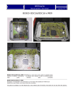
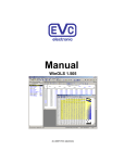
Manual
BDM100
Table of Contents
Title:
Page
Important ..................................................................................................... 3
The BDM100 Module ................................................................................... 3
Interconnections for Bosch EDC16 and ME9 ECUs ................................. 4
Interconnections for Bosch EDC7 ECUs .................................................. 5
Interconnections for Bosch ECUs using a BDM120 Cable ...................... 6
Interconnections for Bosch ME9.0 ECUs.................................................. 7
Interconnections for Bosch ME9.7 ECUs.................................................. 8
Interconnections for Bosch MED9.7 ECUs ............................................... 9
Interconnections for Daimler-Chrysler ETC5 ECUs ............................... 10
Interconnections for Delphi ECUs ........................................................... 11
Interconnections for Delphi DCM3.2 ECUs ............................................. 12
Interconnections for Delphi DCM3.2 (MB Version) ................................ 13
Interconnections for Marelli ECUs .......................................................... 14
Interconnections for Siemens HMC Theta PI ECUs ............................... 16
Interconnections for Siemens MS45 ECUs ............................................. 17
Interconnections for Siemens MSS65 ECUs .......................................... 18
Interconnections for Siemens MSS70 ECUs .......................................... 19
Interconnections for Siemens MSV70 ECUs .......................................... 20
Interconnections for Siemens PPD1.1 ECUs .......................................... 21
Interconnections for Siemens SID201 ECUs .......................................... 22
Interconnections for Siemens SID202 ECUs and SID803A .................... 23
Interconnections for Siemens SID203 ECUs .......................................... 24
Interconnections for Siemens SID204 ECUs .......................................... 25
Interconnections for Siemens SID206 ECUs .......................................... 26
Interconnections for Siemens SID803 ECUs .......................................... 27
Interconnections for Siemens SIM266 ECUs .......................................... 28
Interconnections for Siemens SIM2K ...................................................... 29
Interconnections for Siemens SIM90E ECUs ......................................... 30
Interconnections for Siemens SIM90P ECUs ......................................... 31
Interconnections for Siemens Simos6.x ECUs....................................... 32
The Alignment of the BDM-Port Pads ..................................................... 33
Pin Out BDM100 Module .......................................................................... 34
Pin Out BOSCH System Programming Pads .......................................... 34
Some ECUs with BDM capability ............................................................. 35
EVC electronic GmbH
Am Pfauenzehnt 11a
46539 Dinslaken
www.evc.de
EVC electronic GmbH
-2-
BDM100 Module
EVC electronic GmbH
-3-
BDM100 Module
Important
Disclaimer / Warranty
The BDM module is for use by qualified personnel only. A warranty on our part for direct
damages and consequential damages, caused by the improper handling of our product or
additional products is excluded.
The interconnection between the BDM100 Module and the appropriate ECU is very easy.
Nevertheless you should read this manual carefully, because any failure may result in the destruction
of the ECU.
! To avoid damages on your BDM100-module or on an ECU, please carefully read this manual
before you start running the BDM100 Module with an ECU !
The BDM100 Module
In all cases, always connect the BDM100
module with your PC or notebook, first!
The lower of the both blue LEDs on the
Front panel now should start flashing as
shown in picture A.
The BDM100 module has no own power
source. It’s an USB-Device and obtains
its power via the USB cable.
Pict. A: The BDM100 Module is always connected to
the USB cable first.
Always make sure that all necessary
connections are done, before you apply
power to an ECU!
The upper of the both blue LEDs
indicates that an ECU connected to the
BDM100 module is supplied with the
required voltage (picture B).
Pict. B: The BDM100 module connected to an
engaged ECU.
EVC electronic GmbH
-4-
BDM100 Module
Interconnections for Bosch EDC16 and ME9 ECUs
When the Bosch EDC16 or ME9 ECU is
opened, you may look for a typical 14-pads
arrangement near the back border of the
printed connection board of the ECU.
It should look like as shown in Picture A.
This is the BDM-Port of the Bosch ECUs.
Note that at all only 10 pads of the total 14
pads are used for the EDC16 or ME9
programming port.
The pads with the numbers 3, 4, 13 and 14
are not used.
Ensure that the pads are clean and free of
remaining flux agent.
Pict. A: These are the typical Bosch pads for BDM.
Now place the BDM143 probe into the
positioning frame and connect it to the
BDM100 module
Ensure that the switch of the BDM143 probe
is in its ‘OFF’-position.
Carefully put the tips of the spring contact
probes on the pads on the board as shown
in picture B.
The power supply of the BDM143 probe is
plugged into the power source connector as
shown in picture B.
Now put the switch of the BDM143 in its
‘ON’-position.
Pict. B: The BDM143 probe contacting the pads.
The red LED of the BDM143 and also the
upper of the two blue LEDs on the front
panel of the BDM100 module should light up
to indicate that the ECU board is supplied
with the required voltage.
The BDM100 module is now operational.
Pict. C: Finally the power will applied.
EVC electronic GmbH
-5-
BDM100 Module
Interconnections for Bosch EDC7 ECUs
On the EDC7 board the BDM port pads are
located very near the MPC555 processor.
On Picture A the orientation of the pads
arrangement is shown.
Note that at all only 10 pads of the total 14
are used for the EDC7 programming port.
The pads with the numbers 2,3,13 and 14
are not used.
Ensure that the pads are clean and free of
remaining flux agent.
On the EDC7 board the required pads are
also located in the very middle of the whole Pict. A: This is the characteristic arrangement of
board. Because of this you must not place the Bosch BDM pads.
the BDM143 probe completely into the
guide slot of the positioning frame (as
shown in picture B)
Now connect the BDM143 probe to the
BDM100 module
Ensure that the switch of the BDM143 probe
is in its ‘OFF’-position.
Carefully put the tips of the spring contact
probes on the pads on the board as shown
in picture B.
It is recommended to use an isolation foil, in
order to avoid that the arm of the positioning
frame produces short-circuits between
larger components on the top side of the
Pict. B: The BDM143 probe contacting the pads.
board.
The power for the board will applied over
the power jack on the BDM143 adapter.
If you prefer to use the other BDM port on
the side of the ECU where the main
connectors are mounted on, a BDM141
adapter is required (Pict. C).
In that case the power to the EDC7 board is
provided by the following pins of the main
connectors (A,B):
EDC7 IVECO
EDC7 MAN
GND
B2
A15
BAT+
B12
A7
IGN
B39
B36
Pict. C: The other BDM-port on the top side.
EVC electronic GmbH
-6-
BDM100 Module
Interconnections for Bosch ECUs using a BDM120 Cable
For connecting the BDM100 module to
the EDC16 or to the ME9 ECUs the
BDM120 cable is required which is
equipped with an own power supply
First solder the 12way pin header onto
the pads for the BDM port of the EDC16
or ME9 board (picture A).
Note that at all only 10 pads of the total
14 pads are used for the EDC16 or ME9
programming port.
Pict. A: This is the way the pin header will soldered..
Now take the BDM110 cable and connect
it with the BDM120 cable as shown in
picture B.
Then connect the other side of the
BDM100 cable to the BDM100 module.
Ensure that you have plugged the 12way
connector in the 12way header exactly
as shown in picture B!
Again, ensure that all connections are
plugged in the right direction.
Pict. B: The direction the BDM120 must plugged!
Finally, the power supply of the BDM120
cable is plugged into the power source
connector (picture C).
The upper of the two blue LEDs on the
front panel should light up to indicate that
the ECU board is now supplied with the
required voltage.
The BDM100 module is now operational.
After finishing your work always remove
the power supply from the power plug
connector first before disconnecting any
other connection!
Pict. C: Finally the power will applied.
EVC electronic GmbH
-7-
BDM100 Module
Interconnections Bosch ME9.0 ECUs
Pict. A: The main connector of the Bosch ME9.0 ECU.
On the Bosch ME9.0 ECU the power
distribution is provided by the pins of the
main connector.
Use separate wires with matching
connectors to connect GND and +12Vcc to
the pins of the main connector shown in
picture A.
Now place a BDM144 probe into the
positioning frame and carefully center the
tips of the spring contact probes on the
BDM-pads on the board as shown in picture
B.
The tips of the spring contact probes should
reach a spring travel of 1.5 mm minimum for Pict. B: These are the required pads for the BDM
best contact conditions.
Interface.
Then connect the BDM110 flat wire cable to
the BDM100 module which should already
be connected to your computer.
If you then applying power to the main
connector of the ECU the red LED on the
BDM144 probe lights up to indicate that the
logic on the board is supplied with the
required voltage
The BDM100 module is now operational.
Pict. C: This way the BDM144 probe contacts the
Bosch ME9.0 ECU board..
EVC electronic GmbH
-8-
BDM100 Module
Interconnections Bosch ME9.7 ECUs
Pict. A: The main connector of the Bosch ME9.7 ECU.
On the Bosch ME9.7 ECU the power
distribution is provided by the pins of the
main connector.
Use separate wires with matching
connectors to connect GND and +12Vcc to
the pins of the main connector shown in
picture A.
Now place a BDM141 probe into the
positioning frame and carefully center the
tips of the spring contact probes on the
BDM-pads on the board as shown in picture
B.
The tips of the spring contact probes should
reach a spring travel of 1.5 mm minimum for Pict. B: These are the required pads for the BDM
best contact conditions.
Interface.
Then connect the BDM110 flat wire cable to
the BDM100 module which should already
be connected to your computer.
If you then applying power to the main
connector of the ECU the red LED on the
BDM141 probe lights up to indicate that the
logic on the board is supplied with the
required voltage
The BDM100 module is now operational.
Pict. C: This way the BDM141 probe contacts the
board of the Bosch ME9.0 ECU..
EVC electronic GmbH
-9-
BDM100 Module
Interconnections Bosch MED9.7 ECUs
Pict. A: The main connector of the Bosch MED9.7 ECU.
On the Bosch ME9.7 ECU the power
distribution is provided by the pins of the
main connector.
Use separate wires with matching
connectors to connect GND and +12Vcc to
the pins of the main connector shown in
picture A.
Now place a BDM150 probe into the
positioning frame and carefully center the
tips of the spring contact probes on the
BDM-pads on the board as shown in picture
B.
The tips of the spring contact probes should
reach a spring travel of 1.5 mm minimum for Pict. B: These are the required pads for the BDM
best contact conditions.
Interface.
Then connect the BDM110 flat wire cable to
the BDM100 module which should already
be connected to your computer.
If you then applying power to the main
connector of the ECU the red LED on the
BDM150 probe lights up to indicate that the
logic on the board is supplied with the
required voltage
The BDM100 module is now operational.
Pict. C: This way the BDM150 probe contacts the
Bosch MED9.7 ECU board..
EVC electronic GmbH
-10-
BDM100 Module
Interconnections for Daimler-Crysler ETC5 (P02) V1.1
On the ETC5 ECU the power distribution ist
provided by the following contacts of the
"black" contact chamber (the other contact
chambers are marked with colour bars).
The required contacts for powering up the
ECU are shown in Picture A.
Use separate wires with matching
connectors to connect GND and +12Vcc to
these contact pins.
After removing the top lid of the ECU, you
can see that the PCB is embedded in a
clear but sticky and wobbly silicone mass.
For some versions of the ETC5 ECU, a Pict. A: The power connection on the ETC5 ECU.
BDM149 probe is used to contact the BDMpads on the board by poking the spring
contact pins through the silicone mass.
If you do not use a BDM149 probe, solder a
10-pin header onto the BDM-pads.
The position of pin1- location of the BDMpads is already marked in the PCB layout.
To make the P02- version of the ETC5 ECU
readable and programmable, a track on the
PCB must disrupted as shown in picture B.
For that operation, the silicone mass must
be removed.
If you then applying power to the main
connector of the ECU the red LED of the Pict. B: The position ot the track that must disBDM149 probe (if used) lights up to indicate rupted.
that the logic on the board is supplied with
the required voltage.
The BDM100 module is now operational.
After programming the ECU, it is
recommended to reconnect the disrupted
PCB-track as shown in Picture C.
Pict. C The reconnected track on the ETC5 board.
EVC electronic GmbH
-11-
BDM100 Module
Interconnections for Delphi ECUs
Pict. A: The main connector of the Delphi ECU
In case of a Delphi ECU the power
distribution cannot be provided by special
pads of the BDM port.
Use separate wires to connect GND and
+12Vcc to the pins of the main connector
shown in picture A.
The voltage is provided by a stabilized
power supply or by the main connector of
the ECU at the cable harness of the car.
! Warning ! Please always remind, if the
open ECU is connected to the cable
harness of the car, it is already connected to
the battery!
Please, ensure that the ignition is
switched off while plugging the con- Pict. B: The BDM pads of the Delphi ECU.
nections!
Now place the BDM142 probe into the
positioning frame and carefully put the tips
of the spring contact probes on the pads on
the board as shown in picture C.
The tips of the spring contact probes should
reach a spring travel of 2mm minimum for
best contact conditions.
If you then applying power to the main
connector of the ECU the red LED of the
BDM142 probe lights up to indicate that the
logic on the board is supplied with the
required voltage.
Pict. C: The BDM142 probe contacting the BDM
port pads of a Delphi ECU.
EVC electronic GmbH
-12-
BDM100 Module
Interconnections for Delphi DCM3.2 ECUs
Pict. A: The main connector of the Delphi DCM3.2 ECU.
On the DCM3.2 the required contacts are
located in the smaller chamber of the main
connector (Pict. A)
Use separate wires with matching
connectors to connect GND and +12Vcc to
the pins of the main connector shown in
picture A.
Compared to the standard BDM pin out, the
pin out of the BDM-pads on that board is
mirrored, probably due the board was
programmed first in the factory before
mounting it into the case (Pict. B).
Now place a BDM147 probe into the
positioning frame and carefully put the tips
of the spring contact probes on the pads on
the board as shown in picture C.
Pict. B: The location of the required Pads.
The tips of the spring contact probes should
reach a spring travel minimum of 2mm for
best contact conditions.
If you then applying power to the main
connector of the ECU the red LED of the
BDM147 probe lights up to indicate that the
logic on the board is supplied with the
required voltage.
The BDM100 module is now operational.
Pict. C: Like that the BDM147 probe will be
positioned over the DCM3.2 board.
EVC electronic GmbH
-13-
BDM100 Module
Interconnections for Delphi DCM3.x (MB Version)
Pict. A: The main connector of the Delphi DCM3.2 ECU from Daimler-Chrysler.
On the DCM3.2 the required contacts are
located in the smaller chamber of the main
connector (Pict. A)
Use separate wires with matching
connectors to connect GND and +12Vcc to
the pins of the main connector shown in
picture A
The PCB-Layout of the DCM3.2 from MB
differs slightly from the other versions.
You have to close two jumpers first before
this ECU is readable! (Pict. B)
Compared to the standard BDM pin out, the
pin out of the BDM-pads on that board is
mirrored, probably due the board was
programmed first in the factory before Pict. B: The location of the BDM pads and the two
mounting it into the case (Pict. B).
jumpers you have to close first.
Now place a BDM147 probe into the
positioning frame and carefully put the tips
of the spring contact probes on the pads on
the board as shown in picture C.
The tips of the spring contact probes should
reach a spring travel minimum of 2mm for
best contact conditions.
If you then applying power to the main
connector of the ECU the red LED of the
BDM147 probe lights up to indicate that the
logic on the board is supplied with the
required voltage.
The BDM100 module is now operational.
Pict. C: Like that the BDM147 probe will be
positioned over the DCM3.2 board.
EVC electronic GmbH
-14-
BDM100 Module
Interconnections for Marelli ECUs
Pict. A: The main connector of the Marelli ECU
In case of a Marelli ECU the power
distribution cannot be provided by special
pads of the BDM port.
Use separate wires to connect GND and
+12Vcc to the pins of the main connector
shown in picture A.
The voltage is provided by a stabilized
power supply or by the main connector of
the ECU at the cable harness of the car.
! Warning ! Please always remind, if the
open ECU is connected to the cable
harness, it is already connected to the
battery!
Please, ensure that the ignition is
switched off at beginning!
Before you can start to read out or program
a Marelli ECU, you must solder out the zeroohm resistor witch is next pin19 of the
component with SO28 package in the corner of the ECU board (Pict. B).
Pict. B: The location of the zero-ohm resistor witch
will be out-soldered.
There is also another Type of the Marelli
MJD- ECU which has another PCB-layout
and some other components. There the
zero-ohm resistor is placed near the flashEPROM (Pict. C).
Don’t forget to solder the zero-ohm resistor
on its place again when the work with the
BDM equipment is done.
Pict. C: On this Marelli MJD-ECU (with another
PCB-design) the resistor is already out-soldered.
EVC electronic GmbH
-15-
BDM100 Module
Interconnections Marelli ECUs
The
BDM110-cable
is
made
for
connecting the BDM100 module with
ECUs using a 10way standard BDM-port
with a 0.1’ pitch.
On a Marelli board you will find a 12pad
array with 0.05’ pitch for the BDM port.
Two of them, pad 11 and pad 12 are
unused (Pict. D).
Pict. D: The BDM pads of the Marelli ECU.
Now place the BDM144 probe into the
positioning frame and carefully put the tips
of the spring contact probes on the pads
on the board as shown in picture E.
If the length of the spring contact pins
should be to short, pull the spring contact
pins up to the first rest position from the
receptacles.
The tips of the spring contact probes
should reach a spring travel of 2mm
minimum for best contact conditions.
If you then applying power to the main
connector of the ECU the red LED of the
BDM144 probe lights up to indicate that
the logic on the board is supplied with the
required voltage.
EVC electronic GmbH
Pict. E: The BDM144 probe contacting the BDM port
pads of a Marelli ECU.
-16-
BDM100 Module
Interconnections Siemens HMC Theta PI ECUs
Pict. A: The main connector of the Siemens HMC Theta PI-ECU.
On the Siemens MS45 ECU the power
distribution is provided by the pins of the
main connector as shown in picture A.
Use separate wires to connect GND and
+12Vcc to the pins of the main connector
shown in picture A.
Now place the BDM144 probe into the
positioning frame and carefully put the tips
of the spring contact probes on the pads on
the board as shown in picture C.
If the length of the spring contact pins
should be to short, pull the spring contact
pins up to the first rest position from the
receptacles.
Pict. B: Only ten of the present 12 pads will be
used. The extra both are not connected.
The tips of the spring contact probes should
reach a spring travel of 1mm minimum for
best contact conditions.
If you then applying power to the main
connector of the ECU the red LED of the
BDM144 probe lights up to indicate that the
logic on the board is supplied with the
required voltage
The BDM100 module is now operational
Pict. C: The tips of the spring contact probes
should reach a spring travel of 2mm minimum for
best contact conditions
EVC electronic GmbH
-17-
BDM100 Module
Interconnections for Siemens MS45 ECUs
+12Vcc (1-7)
+12Vcc (4-26)
GND (1-4)
Pict.A: The main connector of the MS45 ECU.
In case of the Siemens MS45 ECU the
power distribution is provided by the pins of
the main connector marked in picture 19.
Use separate wires to connect GND and
+12Vcc to the pins of the main connector
shown in picture A.
The voltage is provided by a stabilized
power supply or by the main connector of
the ECU at the cable harness of the car.
! Warning ! Please always remind, if the
open ECU is connected to the cable
harness of the car, it is already connected to
the battery!
Please, ensure that the ignition is
switched off at beginning!
Pict. B: On the MS45 board the BDM-Pads are
Now place the BDM141 probe into the arranged very centrically.
positioning frame and carefully put the tips
of the spring contact probes on the pads on
the board as shown in picture C.
If the length of the spring contact pins
should be to short, pull the spring contact
pins up to the first rest position from the
receptacles.
The tips of the spring contact probes should
reach a spring travel of 1mm minimum for
best contact conditions.
If you then applying power to the main
connector of the ECU the red LED of the
BDM141 probe lights up to indicate that the
logic on the board is supplied with the
required voltage
The BDM100 module is now operational.
EVC electronic GmbH
Pict. C: The BDM141 contacting BDM- Pads.
-18-
BDM100 Module
Interconnections for Siemens MSS65 ECUs
Pict.A: The main connector of the MSS65 ECU.
On the Siemens MS45 ECU the power
distribution is provided by the pins of the
main connector as shown in picture 19a.
Use separate wires to connect GND and
+12Vcc to the pins of the main connector
shown in picture A.
On the MSS65 board there are two
processors which each own programming
port pad arrays. Each array consists of 30
pads but only the first 10 of them are used
for BDM purposes.
For connecting the BDM-pads controllable
the BDM141 and also the BDM144 probe
are required.
Now place the BDM probes in succession Pict. B: On the MSS65 board both the BDM144
into the positioning frame and carefully put (shown in this picture) and the BDM141 probes are
the tips of the spring contact probes on the required.
pads on the board as shown in picture B
and picture C.
If the length of the spring contact pins
should be to short, pull the spring contact
pins up to the first rest position from the
receptacles.
The tips of the spring contact probes should
reach a spring travel of 1mm minimum for
best contact conditions.
If you then applying power to the main
connector of the ECU the red LED of the
BDM14x probe lights up to indicate that the
logic on the board is supplied with the
required voltage
The BDM100 module is now operational
EVC electronic GmbH
Pict. C: The BDM141 probe contacting the BDMpads of the second processor..
-19-
BDM100 Module
Interconnections for Siemens MSS70 ECUs
Pict. A: The main connector of the Siemens MSS70 ECU like on the MSV70 ECU.
The programming of the MSS70 ECU is
very similarly to the programming of the
MSV70 ECU.
On the Siemens MSS70 ECU the power
distribution is provided by the pins of the
main connector as shown in picture A.
Use separate wires to connect GND and
+12Vcc to the pins of the main connector
shown in picture A
Don't forget to close the jumper pads shown
on picture B!
Now place the BDM141 probe into the
positioning frame and carefully centre the Pict. B: This are the pads which are required fo the
tips of the spring contact probes on the BDM interface.
BDM-pads on the board as shown in picture
B.
Then connect the BDM110 flat wire cable to
the BDM100 module which must already be
connected to your computer.
The tips of the spring contact probes should
reach a spring travel of 1mm minimum for
best contact conditions.
If you then applying power to the main
connector of the ECU the red LED of the
BDM141 probe lights up to indicate that the
logic on the board is supplied with the
required voltage
The BDM100 module is now operational.
EVC electronic GmbH
Pict.C: Make sure, that you are not producing
short circuits, if you are lowering the arm of the
positioning frame!
-20-
BDM100 Module
Interconnections for Siemens MSV70 ECUs
Pict. A: The main connector of the Siemens MSV70 ECU (equal to the one of the MSS65 ECU).
On the Siemens MSV70 ECU the power
distribution is provided by the pins of the
main connector as shown in picture 31.
Use separate wires to connect GND and
+12Vcc to the pins of the main connector
shown in picture A
To make the BDM100-Modul able to
recognize the ECU, a drop of solder or a
zero-Ohm resistor is required. Place it
between the both solder pads which are
marked by a yellow circle on picture B.
Now place the BDM141 probe into the
positioning frame and carefully center the
tips of the spring contact probes on the Pict. B: This are the pads which are required fo the
BDM-pads on the board as shown in picture BDM interface. The required jumper is marked by a
C.
yellow circle.
Then connect the BDM110 flat wire cable to
the BDM100 module which must already be
connected to your computer.
The tips of the spring contact probes should
reach a spring travel of 1mm minimum for
best contact conditions.
If you then applying power to the main
connector of the ECU the red LED of the
BDM141 probe lights up to indicate that the
logic on the board is supplied with the
required voltage
The BDM100 module is now operational.
Pict.C: Make sure, that you are not producing
short circuits, if you are lowering the arm of the
positioning frame!
EVC electronic GmbH
-21-
BDM100 Module
Interconnections for Siemens PPD1.1 ECUs
Pict. A: The main connector of the Siemens PPD1.1 ECU.
On the Siemens PPD1.1 ECU the power
distribution is provided by the pins of the
main connector as shown in picture A.
Use separate wires to connect GND and
+12Vcc to the pins of the main connector
shown in picture A
Now place the BDM144 probe into the
positioning frame and carefully center the
tips of the spring contact probes on the
BDM-pads on the board as shown in picture
B.
Then connect the BDM110 flat wire cable to
the BDM100 module which is already
connected to your computer.
Pict. B: This are the pads which are required for the
BDM interface.
The tips of the spring contact probes should
reach a spring travel of 1mm minimum for
good contact conditions.
If you then applying power to the main
connector of the ECU the red LED on the
BDM144 probe lights up to indicate that the
logic on the board is supplied with the
required voltage
The BDM100 module is now operational.
Pict. C: In this case the BDM144 probe is best
suited for contacting the BDM-pads on the PPD1.1.
EVC electronic GmbH
-22-
BDM100 Module
Interconnections for Siemens SID201 ECUs
Pict.A: The main connector of the Siemens SID201 ECU.
In case of the Siemens SID201 ECU the
power distribution is provided by the pins of
the main connector marked in picture A.
Use separate wires to connect GND and
+12Vcc to the pins of the main connector
shown in picture A.
The voltage is provided by a stabilized
power supply or by the main connector of
the ECU at the cable harness of the car.
! Warning ! Please always remind, if the
open ECU is connected to the cable
harness of the car, it is already connected to
the battery!
Please, ensure that the ignition is Pict. B: The location of the BDM- Pads on the board
switched off at beginning!
of the Siemens SID201 ECU.
Now place the BDM141 probe into the
positioning frame and carefully put the tips
of the spring contact probes on the pads on
the board. If the length of the spring contact
pins is not long enough, pull the spring
contact pins up to the first rast position from
the receptacles.
The tips of the spring contact probes should
reach a spring travel of 1mm minimum for
best contact conditions.
If you then apply power to the main
connector of the ECU, the red LED of the
BDM141 probe lights up to indicate that the
logic on the board is supplied with the
required voltage
EVC electronic GmbH
Pict. C: The BDM141 contacting the BDM- Pads.
-23-
BDM100 Module
Interconnections for Siemens SID202 and SID803A ECUs
Pict.A: The connections for power and ignition for the SID202 ECU are the same as on the
Siemens SID803(A) ECU.
This instruction for the SID202 ECU is also
valid for the SID803A ECU.
In case of the Siemens SID202 ECU the
power distribution is provided by the pins of
the main connector marked in picture 16a.
Use separate wires to connect GND and
+12Vcc to the pins of the main connector
shown in picture A.
The voltage is provided by a stabilized
power supply or by the main connector of
the ECU at the cable harness of the car.
! Warning ! Please always remind, if the
open ECU is connected to the cable
harness of the car, it is already connected to Pict. B: The location of the BDM- Pads on the board
the battery!
of the Siemens SID202 ECU
Please, ensure that the ignition is
switched off at beginning!
Now place the BDM141 probe into the
positioning frame and carefully put the tips
of the spring contact probes on the pads on
the board. If the length of the spring contact
pins is not long enough, pull the spring
contact pins up to the first rast position from
the receptacles.
The tips of the spring contact probes should
reach a spring travel of 1mm minimum for
best contact conditions.
If you then apply power to the main
connector of the ECU, the red LED of the
BDM141 probe lights up to indicate that the
logic on the board is supplied with the
required voltage
EVC electronic GmbH
-24-
BDM100 Module
Interconnections for Siemens SID203 ECUs
Pict.A: The connections for power and ignition for the SID203 ECU are the same as on the
Siemens SID201 ECU.
In case of the Siemens SID203 ECU the
power distribution is provided by the pins of
the main connector marked in picture 16a.
Use separate wires to connect GND and
+12Vcc to the pins of the main connector
shown in picture A.
The voltage is provided by a stabilized
power supply or by the main connector of
the ECU at the cable harness of the car.
! Warning ! Please always remind, if the
open ECU is connected to the cable
harness of the car, it is already connected to
the battery!
Please, ensure that the ignition is Pict. B: The location of the BDM- Pads on the board
switched off at beginning!
of the Siemens SID203 ECU.
Don't forget to close the jumper! For the BDMNow place the BDM141 probe into the module this is necessary to recognize the ECU.
positioning frame and carefully put the tips
of the spring contact probes on the pads on
the board. If the length of the spring contact
pins is not long enough, pull the spring
contact pins up to the first rast position from
the receptacles.
The tips of the spring contact probes should
reach a spring travel of 1mm minimum for
best contact conditions.
If you then apply power to the main
connector of the ECU, the red LED of the
BDM141 probe lights up to indicate that the
logic on the board is supplied with the
required voltage
EVC electronic GmbH
-25-
BDM100 Module
Interconnections for Siemens SID204 ECUs
Pict.A: The connections for power and ignition for the SID204 ECU are the same as on the
Siemens SID201 ECU.
In case of the Siemens SID204 ECU the
power distribution is provided by the pins of
the main connector marked in picture 16a.
Use separate wires to connect GND and
+12Vcc to the pins of the main connector
shown in picture A.
The voltage is provided by a stabilized
power supply or by the main connector of
the ECU at the cable harness of the car.
! Warning ! Please always remind, if the
open ECU is connected to the cable
harness of the car, it is already connected to
the battery!
Please, ensure that the ignition is Pict. B: The location of the BDM- Pads on the board
switched off at beginning!
of the Siemens SID204 ECU.
Now place the BDM141 probe into the
positioning frame and carefully put the tips
of the spring contact probes on the pads on
the board. If the length of the spring contact
pins is not long enough, pull the spring
contact pins up to the first rast position from
the receptacles.
The tips of the spring contact probes should
reach a spring travel of 1mm minimum for
best contact conditions.
If you then apply power to the main
connector of the ECU, the red LED of the
BDM141 probe lights up to indicate that the
logic on the board is supplied with the
Pict. C: The BDM141 probe contacting the BDM
required voltage
pads on the board of the Siemens SID204 ECU
EVC electronic GmbH
-26-
BDM100 Module
Interconnections for Siemens SID206 ECUs
Pict.A: The connections for power and ignition for the SID206 ECU are the same as on the
Siemens SID803 ECU.
In case of the Siemens SID206ECU the
power distribution is provided by the pins of
the main connector. The concerned pins are
marked in picture 16a.
Use separate wires to connect GND and
+12Vcc to the pins of the main connector
shown in picture A
The voltage is provided by a stabilized
power supply or by the main connector of
the ECU at the cable harness of the car.
! Warning ! Please always remind, if the
open ECU is connected to the cable
harness of the car, it is already connected to
the battery!
Please, ensure that the ignition is
switched off at beginning!
Now place the BDM141 probe into the
positioning frame and carefully put the tips
of the spring contact probes on the pads on
the board. If the length of the spring contact
pins is not long enough, pull the spring
contact pins up to the first rast position from
the receptacles.
The tips of the spring contact probes should
reach a spring travel of 1mm minimum for Pict. B: The BDM141 probe contacting the BDM
pads on the board of the Siemens SID206 ECU
best contact conditions.
If you then apply power to the main The position of pin1 you can infer from the BDM141
connector of the ECU, the red LED of the probe above the pads. Don't forget to close the
BDM141 probe lights up to indicate that the jumper (red arrow).
logic on the board is supplied with the
required voltage
EVC electronic GmbH
-27-
BDM100 Module
Interconnections for Siemens SID803 ECUs
Pict.A: The main connector of the Siemens SID803 ECU.
In case of the Siemens SID803 ECU the
power distribution is provided by the pins of
the main connector marked in picture 16.
Use separate wires to connect GND and
+12Vcc to the pins of the main connector
shown in picture A.
The voltage is provided by a stabilized
power supply or by the main connector of
the ECU at the cable harness of the car.
! Warning ! Please always remind, if the
open ECU is connected to the cable
harness of the car, it is already connected to
the battery!
Please, ensure that the ignition is
switched off at beginning!
Now place the BDM141 probe into the
positioning frame and carefully put the tips
of the spring contact probes on the pads on
the board as shown in picture 18. If the
length of the spring contact pins should be
to short, pull the spring contact pins up to
the first rest position from the receptacles.
Pin 1
Pict. B: The location of the BDM- Pads on the board
of the Siemens SID803 ECU.
The tips of the spring contact probes should
reach a spring travel of 1mm minimum for
best contact conditions.
If you then applying power to the main
connector of the ECU the red LED of the
BDM141 probe lights up to indicate that the
logic on the board is supplied with the
required voltage
Pict. C: The BDM141 contacting the BDM- Pads.
EVC electronic GmbH
-28-
BDM100 Module
Interconnections for Siemens SIM266 ECUs
Pict. A: The main connector of the SIM266 ECUs.
On the Siemens SIM266 ECU the power
distribution is provided by the pins of the
main connector as shown in picture A.
Use separate wires to connect GND and
+12Vcc to the pins of the main connector
shown in picture.A
Although the BDM pads don’t appear in a
well-known arrangement on the Siemens
SIM266 ECU board, the BDM145 probe
provides a solution to contact the required
BDM pads which are scattered all over the
top side of the ECU board.
After removing the back plate of the ECU
you will look for the PCP area the required Pict. B: This are the pads which are required for
pads are located in (as shown in Pict. B).
the BDM interface.
Use a support padding with 10mm thickness
and 100mm x 150mm in size under the ECU
to get a horizontally alignment of the ECU
board with the positioning frame base plate.
Now place the BDM145 probe into the
positioning frame and carefully put the tips
of the spring contact probes on the pads on
the board as shown in picture C.
Use the representation in Pict. 26 for orientation and make sure that the spring contact probe hits centrically the correct pads
before you switch on the power.
Pict. C: The tips of the spring contact probes
should reach a spring travel of 2mm minimum for
best contact conditions
EVC electronic GmbH
-29-
BDM100 Module
Interconnections for Siemens SIM2K ECUs
Pict. A: The main connector of the SIM2K ECU.
On the SIM2K ECU the power distribution is
provided by the stronger contact pins of the
lage contact chamber of the main
connector.
Use separate wires to connect GND, IGN
and +12Vcc to the pins of the main
connector shown in picture.A
Attention:
On the SIM2K board a 12-pad array is
located as shown in picture B
Two opposite pads of that pad-array are not
connected to a conductor trace and that is Pict. B: the text on the left explains why in this case
why they left uncontacted both.
Pin1 is on the second position.
The ten spring contacts of the BDM144
probe will only contact the lower ten
pads of the pad array.
The both pads in front of the array will not
be contacted as shown in picture C.
Now place the BDM144 probe into the
positioning frame and carefully put the tips
of the spring contact probes on the pads on
the board. If the length of the spring contact
pins is not long enough, pull the spring
contact pins up to the first rast position from
their receptacles.
Pict. C: The BDM144 probe contacts the board of
the SIM2K ECU.
EVC electronic GmbH
-30-
BDM100 Module
Interconnections for Siemens SIM90E
Pict. A: The main connector on the SIM90E ECU.
On the SIM90P ECU the power connections
are made to the smaller one of the two
contact chambers.
Use separate wires with matching
connectors to connect GND, IGN and
+12Vcc to the pins of the main connector as
shown in picture A.
The position of the required array and the
alignment of pin 1 is shown in picture B.
For contacting the pad array you best use a
BDM141 probe in the positioning frame.
Pict. B: the BDM-port on the Sim90E ECU.
EVC electronic GmbH
-31-
BDM100 Module
Interconnections for Siemens SIM90P
Pict. A: The main connector on the SIM90P ECU.
On the SIM90P ECU the power connections
are made to the smaller one of the two
contact chambers.
Use separate wires with matching
connectors to connect GND, IGN and
+12Vcc to the pins of the main connector as
shown in picture A.
Caution!
There are two pad arrays on the ECU board
which are looking like BDM-Ports.
Please ensure that you chose the right one.
The position of the required array and the
alignment of pin 1 is shown in picture B.
Bild B: This is the pad array of the BDM-port. Do
not take the wrong of the both pad arrays.!
For contacting the pad array you best use a
BDM141 probe in the positioning frame.
To make the ECU programmable, a jumper
must be made on the side of the board
where the microcontroller is placed.
On picture C, the both concerned pads
already are connected with a drop of solder.
That connection is necessary for making the
BDM-interface operable but it does not
affect the functionality of the ECU so it may
remain.
Bild C: This is the location for the required jumper.
EVC electronic GmbH
-32-
BDM100 Module
Interconnections for Siemens SIMOS-6.x ECUs
Pict. A: : The main connector of the SIMOS-6.x ECU series.
On the Siemens SIMOS-6.x ECU series the
power distribution is provided by the pins of
the main connector as shown in picture A.
Use separate wires to connect GND and
+12Vcc to the pins of the main connector
shown in picture A
Although the BDM pads do not appear in a
well-known arrangement on the ECU board,
the BDM146 probe provides a solution to
contact the required BDM pads which are
scattered all over the top side of the ECU
board like shown in Pict.B.
The required pads are marked with orange
circles and the resulting location of the
BDM146 probe board is shown like a blue Pict. B: This are the pads which are required for
shadow.
the BDM interface.
After removing the back plate of the ECU
you will look for the PCP area the required
pads are located in (as shown in Pict. B).
Now place the BDM146 probe into the
positioning frame and carefully put the tips
of the spring contact probes on the pads on
the board as shown in picture C.
Then connect the BDM110 flat wire cable to
the BDM100 module which must already be
connected to your computer.
Use the representation in Pict. B for
orientation and make sure that the spring
con-tact probe hits centrically the correct
pads before you switch on the power.
Pict. C: The tips of the spring contact probes
should reach a spring travel of 2mm minimum for
best contact conditions
EVC electronic GmbH
-33-
BDM100 Module
The Alignment of the BDM-Port Pads
On the most ECU Boards the location of
pin 1 of the BDM-port pads are not
marked in any way. This application
note will demonstrate how you can
estimate the location of Pin1 of the
BDM-port pads in the very most cases.
The figure on the right shows the
Motorola (TM) standard pinout of the
BDM-port:
VFLS0
GROUND
GROUND
HRESET
Power (+3.3 V)
1
3
5
7
9
2
4
6
8
10
SRESET
TCK/DSCK
VFLS1
TDI/DSDI
TDO/DSDO
Fig. 1: This is the standard BDM-port pinout.
Regarding the pinout of the standard
BDM-port it is obvious that two of them
are grounded. These are the pins 3 and
5. So the pin 1 is above them.
Which of the pads are grounded you can
find out simply using an ohmmeter or a
diode-tester.
Finally let us demonstrate this again in
the next three steps using a SMD
footprint of the BDM-port pads:
1st. step:
Fig. 2: This the typical arrangement of the BDM pads.
2nd. step:
Fig. 3: Then estimate which pads are grounded
2
4
6
8
10
1
3
5
7
9
3rd. step:
Fig. 4: The pin1 is left of the two grounded pins, as
agreed.
EVC electronic GmbH
-34-
BDM100 Module
Pin Out BDM100 Module
Picture A shows the pinout of the 10way
pin header located on the back of the
BDM100 Module.
This pinout appropriates the standard
BDM port pinout.
On ECUs equipped with a 10way BDMport the interconnection can made by
using a simple 10way flat- wire cable. In
this case the location of pin 1 of the BDMport on the ECU board should be known.
Pict. A: The pinout of the 10way pin header
Pin Out BOSCH System Programming Pads
The pad arrangement of the BOSCH
ECUs differs from the MOTOROLA
standard.
The 12Vcc clamp voltage from the battery
and also the 12Vcc from the Ignition or
wake up circuit are present in that pad
array.
Picture B shows which signals and
voltages were assigned to the pads.
Please consider that in early EDC16
ECUs the 3.3V pad is driven by a 5V
circuit.
Pict. B: The pinout of the BOSCH programming pads.
Signal Names Assignment
.The table on the right shows the signal
names assignment for both by Bosch and
by Motorola.
The pin numbering is only valid for the
BDM interface by Motorola.
In which manner the pad array by Bosch
will be counted, is unknown.
EVC electronic GmbH
Pin Nr.
Motorola
Bosch
1..............VFLS0................VF0
2..............SRESET#...........nicht vorhanden
3..............GND...................GND
4..............DSCK.................DSCK
5..............GND...................GND
6..............VFLS1................VF1
7..............HRESET#..........PORST
8..............DSDI..................DSDI
9..............VDD SENSE......3.3V
10..............DSDO................DSDO
-35-
BDM100 Module
Some ECUs with BDM capability
Producer
Bosch
Bosch
Bosch
Bosch
Delphi
Delphi
Marelli
Siemens
Siemens
Siemens
Siemens
Siemens
Siemens
Name
EDC16
EDC16+
ME9 Volvo
ME9 BMW
DCM3.2
MJD
SID201
SID803
MS45
MSS65
SIM266
Simos 6.x
Cars (e.g.)
VAG Diesel
PSA Diesel
Volvo Gasoline
BMW v8
Ford Mondeo
Ssangyong
Opel, Fiat
Jaguar 2.7D
Volvo Diesel
BMW 6-Zyl
BMW M5 V10
MB A200
Audi A6 2.4L V6
Processor
MPC556
MPC562
MPC562
MPC555
MPC555
MPC564
MPC555
MPC563
MPC555
MPC555
MPC555
MPC561
MPC561
Used Adapters
BDM143
BDM143
BDM143
BDM143
BDM142*
BDM147*
BDM144*
BDM141*
BDM141*
BDM141*
BDM141+BDM144*
BDM145*
BDM146*
* with this ECUs an external power supply is required. In the case of using a professional laboratory
power supply the knowledge of the main connector pinout of the ECU is necessary
BDM 100 Manual
BDM 100 Manual:
January 15th , 2013
15th edition, 0th revision
Publisher:
EVC electronic GmbH, 46539 Dinslaken
Author:
Matthias Billian
Although we were afforded to describe all details with the highest possible precision, nevertheless we
cannot guarantee an error free content of this manual.
EVC electronic GmbH
Am Pfauenzehnt 11a
46539 Dinslaken
www.evc.de
EVC electronic GmbH
-36-
BDM100 Module