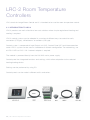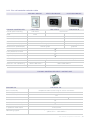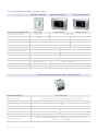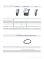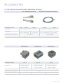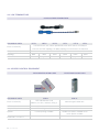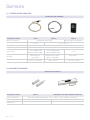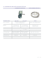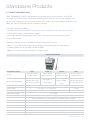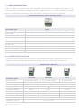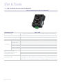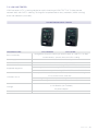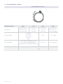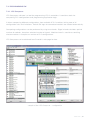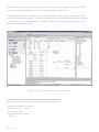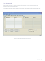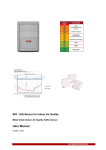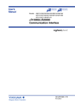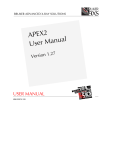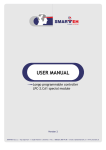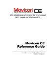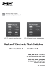
1
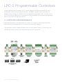
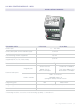
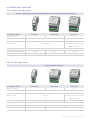
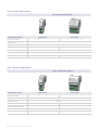
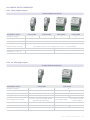
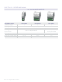
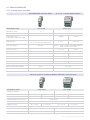
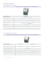
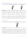
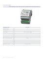
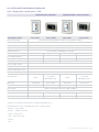
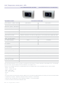
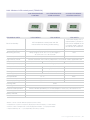
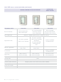
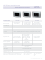
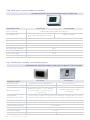
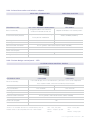
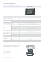
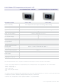
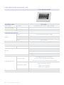
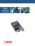
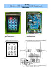
General catalogue
Product Overview
Product overview
SMARTEH PRODUCT LINE
4
1.1. Standards and provisions
4
1.2. Environment
4
LPC-2 PROGRAMMABLE CONTROLLERS
5
2.1. Controller configuration basics
6
2.2. Main Control Modules – MCU
7
2.3. Networking modules
8
2.4. Communication modules
8
2.5. Digital input modules
9
2.5.1. Voltage free digital input
9
2.5.2. 24 VDC digital inputs
9
2.5.3. 24 VAC digital inputs
10
2.5.4. 230 VAC digital inputs
10
2.6. Digital output modules
11
2.6.1. Relay digital outputs
11
2.6.2. Transistor 24 VDC digital outputs
11
2.6.3. Triac 24 .. 230 VAC digital outputs
12
2.7. Analog modules
13
13
2.7.1. Analog inputs & outputs
2.8. Dedicated modules
14
2.8.1. Stepper motor and encoder
14
2.8.2. Differential pressure module
14
2.8.3. DC special digital output
15
2.8.4. Dimmer output
15
2.8.5. Room module
16
2.9. Intelligent peripheral modules
17
2.9.1. Temperature control panel - LED
17
2.9.2. Temperature control panel – LCD
18
2.9.3. Wireless control panel – LCD
19
2.9.4. RFID access control and holder (wall mount)
20
2.9.5. RFID access control and holder (flush mount)
21
2.9.6. RFID access control (outdoor installation)
22
2.9.7. Temperature, humidity and air quality sensors
22
2.9.8. Infrared transceiver and wireless adapter
23
2.9.9. Custom design LCD panels
23
2.10. Operator terminals
24
2.10.1. Text display operation terminal - LCD
24
2.10.2. Modbus RTU Temperature control panel - LCD
25
2.10.3. Touch screen control panel – LCD
26
LRC-2 ROOM TEMPERATURE CONTROLLERS
27
3.1. Introduction to LRC-2
28
3.1.1. Fan coil controller selection table
29
3.1.2. Chilled beam controller selection table
30
3.1.3. LRC networking modules
31
3.1.4. Connection of LRC networking modules
31
ACCESSORIES
32
4.1. For connection of intelligent peripheral modules
33
4.2. LON terminators
34
4.3. Access control equipment
34
SENSORS
35
5.1. Temperature sensors
36
5.2. Magnetic sensors
36
5.3. Condensation and water leakage detectors
37
STANDALONE PRODUCTS
38
6.1. GSM COMMANDER GM-2
39
6.2. Silent motor drive LMD-2
40
6.3. Power supply modules
40
SW & TOOLS
41
7.1. USB to serial RS-232 / RS-485 adapter
42
7.2. LON line tester
43
7.3. Programming cables
44
7.4. Programming SW
45
7.4.1. LPC Composer
45
7.4.2. GSM Manager
47
Copyright © 2006-2014, SMARTEH d.o.o.
GENERAL CATALOGUE
Document Version: V.09, September 2014
Smarteh Product Line
Smarteh programmable controllers are developed to offer efficiency for building automation and small
automation systems. Do not be misguided by “small”, since networking capability can also support
big distributed systems as well. Moreover, dedicated modules for building automation make Smarteh
LPC-2 products very effective for building automation.
Openness & connectivity
Integrated or optional networking and communication possibilities allow you to create high
performance and economical solutions at the same time.
Simplicity
Smarteh programmable controllers provide simple & intuitive solutions to satisfy end-user’s needs by using
free programming software supporting all 5 programming languages defined in IEC 61131-3 standard.
Effectiveness
Parameterization is a candy for the integrators. It gives them possibility to simplify commissioning by making
standard software for similar applications. On site commissioning is reduced to simple parameter settings.
Comfort & economy
We offer cost effective and innovative solutions to provide comfort and energy savings. In building
automation many types of controls can be used. From classic light switches up to Smarteh color LCD touch
button panels and touch screens. Energy savings are achieved by effective management of lighting, heating,
air-conditioning, access control and other appliances, connected and controlled through our HW & SW.
1.1 Standards & Provisions
LPC-2
EMC
EN 61000-6-2 (EN 50082), EN 61000-6-4 (EN 50081)
LVD
IEC 61131-2
Vibrations and climatic, mechanical
EN 60068-2-6, EN 60068-2-27, EN 60068-2-29
LRC-2
EMC
EN 60945
LVD
IEC 61010-1
Vibrations and climatic, mechanical
IEC 68-2-6, IEC 68-2-27, IEC 68-2-14
1.2 Environment
LPC-2 & LRC-2
Temperature
Operation
0 to 50 °C
Storage
-20 to 60 °C
Relative humidity
max. 95%, no condensation
Permissible altitude
2000 m
Pollution degree
II
Protection class
IP 30
4 | Smarteh Product Line
lpc-2
Programmable
Controllers
LPC-2 Programmable Controllers
Longo Programmable Controller LPC-2 is open programmable logic controller for use in
automation, supervision and control solutions. Controller supports many possibilities in
programming, including all five IEC-61131-3 programming languages (FBD, LD, SFC, ST, IL)
and is easy to use. Modular LPC-2 controller architecture offers many different configuration
options and communication possibilities.
2.1. Controller configuration basics
Main control module is the heart of LPC-2 system. Its purpose is to execute application
software and to exchange data with I/O and communication modules.
The controller module is powered directly from the main power supply (115/230 VAC) and
provides the power supply to the attached modules over internal bus.
6 | LPC-2 Programmable Controllers
2.2. Main Control Modules – MCU
Main control modules
LPC-2.MC8
technical data
LPC-2.MC9
Power supply
100 .. 250 VAC
Power consumption for CPU and BUS supply
25 W max
Nr. of I/O & communication modules supported
up to 7
LON networking modules supported
up to 2
Number of intelligent peripheral modules
up to 16
supported (RFID, IR, LCD, VOC,wireless)
Real time clock
integrated
Data storage - 2 Gb
Integrated ports
none
micro SD card
Smarteh RS-485
Smarteh RS-485 Modbus
Modbus TCP/IP
TCP/IP Slave Modbus RTU
Slave 2 x CANopen
Master/Slave 2 x CANopen
Communication ports
LON FT-10* EnOcean*
Optional modules
GSM SMS protocol IR
(intelligent module) DALI/DSI master
Programming port
Programming SW
USB
USB, Ethernet
LPC Composer
Programming standard
IEC 61131-3 (FBD, LD, SFC, ST, IL)
Dimensions L x W x H
90 x 53 x 77 mm
* Networking modules are used to extend networking capability of controller units
LPC-2 Programmable Controllers | 7
2.3. Networking modules
lon
technical data
LPC-2.NL2
Power supply
from internal BUS
Power consumption (BUS)
0.5 W
Dimensions L x W x H
90 x 18 x 60 mm
Communication port
LonWorks
Communication protocol
LonTalk
Connection
screw type
Compliant to
LON TP/FT-10, 78kbps
User defined
LON interface file *.xif
Configuration SW
LonMaker
2.4. Communication modules
IR
GSM
DALI/DSI
ENOCEAN
LPC-2.DL1
LPC-2.EO1
For the IR (infra-red)
and WA1 (wireless)
communication modules
see section 2.8.6 –
Intelligent Modules
technical data
LPC-2.C05
Power supply
from internal BUS
Power consumption (BUS)
1W
Functional description
2W
0.5 W
communication extension
Connection
wireless
screw type
wireless
GSM SMS messaging
DALI or DSI
EnOcean
Functionality
master/slave
master & power supply
transceiver
Compliant to
GSM900 & GSM1800
DALI & DSI
 868.3 MHz EnOcean radio
up to 160 GSM nrs. (users)
up to 64 slave devices
up to 5 input & output devices
GSM Manager
-
WinEtel, LPC Tester
Communication protocol
Limitations
Configuration SW
Dimensions L x W x H
8 | LPC-2 Programmable Controllers
90 x 53 x 60 mm
90 x 18 x 60 mm
2.5. Digital input modules
2.5.1. Voltage free digital inputs
Digital inputs for direct connection of voltage free (dry) contacts
technical data
Number of inputs
LPC-2.DI1
LPC-2.DI5
8
1
Voltage
LPC-2.I16
16
24 VDC (35 VDC max)
24 VDC
jumper selectable in 2
Voltage source
groups of 8 inputs: internal
Internal BUS
BUS or external
on: < 5 kΩ, off: > 40 kΩ
Input threshold
Power consumption (BUS)
Dimensions L x W x H
1.5 W
0.5 W
90 x 18 x 60 mm
2.5 W
90 x 53 x 60 mm
2.5.2. 24 VDC digital inputs
24 V DC digital inputs
technical data
Number of inputs
LPC-2.DI3
LPC-2.DI6
LPC-2.I16
8
1
16
24 VDC (35 VDC max)
Voltage (max)
jumper selectable in 2
Voltage source
groups of 8 inputs: internal
external
BUS or external
Input resistance
2.7 kΩ
Dimensions L x W x H
4.7 kΩ
U > 15 V, U < 2 V0.25 W
Input threshold (On,Off)
Power consumption (BUS)
3.6 kΩ
0.25 W
0.25 W
90 x 18 x 60 mm
90 x 53 x 60 mm
LPC-2 Programmable Controllers | 9
2.5.3. 24 VAC digital inputs
24 V AC digital inputs
technical data
LPC-2.DI7
LPC-2.DI4
1
Number of inputs
8
Voltage (max)
24 (32) VAC
Voltage source
external
2.7 kΩ
Input resistance
Input threshold (On,Off)
3.6 kΩ
U > 15 V, U < 2 V
Power consumption (BUS)
0.25 W
90 x 18 x 60 mm
Dimensions L x W x H
90 x 53 x 60 mm
2.5.4. 230 VAC digital inputs
230 V AC digital inputs
LPC-2.DI2
technical data
LPC-2.DI8
1
Number of inputs
8
Voltage (max)
230 (260) VAC
Voltage source
external
72 kΩ
200 kΩ
U > 150 VAC, U < 20 VAC
U > 60VAC, U < 22 VAC
Input resistance
Input threshold (On,Off)
Power consumption (BUS)
Dimensions L x W x H
10 | LPC-2 Programmable Controllers
0.25 W
90 x 18 x 60 mm
90 x 53 x 60 mm
2.6. Digital output modules
2.6.1. Relay digital outputs
Relay digital outputs
technical data
LPC-2.DO2
Number of outputs
Output type
LPC-2.DO3
1
8
8
relay, NO
relay, NC
relay, NO
relay, NC
230 VAC
230 VAC/3 A, 30 VDC/3 A, 48 VDC/1 A
Switching power (resistive
Power consumption (BUS)
Dimensions L x W x H
LPC-2.DO8
1
Voltage (max)
load per output channel)
LPC-2.DO6
For inductive loads use of suppression circuits is recommended.
0.5 W
2.75 W
90 x 18 x 60 mm
90 x 53 x 60 mm
2.5.2. 24 VDC digital inputs
24 VDC digital outputs
technical data
Number of outputs
Output supply
LPC-2.DO1
1
BUS powered
Output type
transistor output
Voltage (max)
24 VDC ±35 %
Switching power on output
Max. load capacitance/channel
Power consumption (BUS)
Dimensions L x W x H
LPC-2.O16
100 mA, short circuit proof, output
powered from BUS only
16
BUS powered
transistor output
24 VDC
90 x 18 x 60 mm
20 .. 28 VDC
100 mA per module
0.75 W
ext. power supply
500 mA per channel,
4 A per module
10 μF
3W
1W
90 x 53 x 60 mm
LPC-2 Programmable Controllers | 11
2.6.3. Triac 24 .. 230 VAC digital outputs
24 .. 230 V AC digital outputs
technical data
LPC-2.DO4
LPC-2.DO9
LPC-2.DO7
Number of outputs
1
4
8
Output type
zero crossing triac
Voltage (max)
Switching power on
output channel
24 .. 230 V AC (external power supply)
0.05 .. 1.8 A per channel
Dimensions L x W x H
12 | LPC-2 Programmable Controllers
1000 W per module
1 Hz
Switching frequency
Power consumption (BUS)
0.05 .. 0.9 A per channel,
0.25 W
90 x 18 x 60 mm
1W
0.75 W
90 x 53 x 60 mm
2.7. Analog modules
2.7.1. Analog inputs & outputs
Temperature analog input
technical data
0..10 V & 4..20 mA mixed in/out
LPC-2.A02
LPC-2.A01
Number of inputs
2
6
Number of outputs
-
2
Input output type
individually jumper selectable
-
voltage
current
thermocouples E,J,K,N,R,S,T, NTC
10k, Pt100, Pt1000 and Ni1000
0..10 V
0..20 mA
Type of inputs
passive / active, jumper selectable reference:
GND, 24 VDC or 10 VDC
Input connection
passive
Input resistance
-
Input resolution
0.1 °C
Measuring error of full scale
< ±1 %
< ±0.5 %
< ±0.1 %
Type of outputs
-
0..10 V
0..20 mA
Output resolution of full scale
-
Output accuracy
-
10.7 kΩ
3900 levels of full scale
450 levels
< ±0.1 %
< ±0.3 %
from internal BUS
Power supply
Power consumption (BUS)
Dimensions L x W x H
182 Ω
2W
5 W max
90 x 18 x 60 mm
90 x 53 x 60 mm
Analog output 0..20mA current and/or 0..10V voltage
technical data
LPC-2.A03
Number of outputs
LPC-2.A04
2
8
Output type individually selectable
voltage
current
voltage
current
Type of outputs
0..10V
0..20mA
0..10V
0..20mA
5000 levels
Output resolution of full scale
Output accuracy of full scale
Load resistance
±2 %
R > 500 Ω
±1 %
R < 500 Ω
Dimensions L x W x H
R < 500 Ω
from internal BUS
Power supply
Power consumption (BUS)
R > 500 Ω
1W
5W
90 x 18 x 60 mm
90 x53 x 60 mm
LPC-2 Programmable Controllers | 13
2.8. Dedicated modules
2.8.1. Stepper motor and encoder
Stepper motor output module with encoder input
LPC-2.ED1
technical data
Number of outputs/inputs
4 (1 step motor) / 6 (1 encoder)
Output type (motor)
bipolar stepper motor drive (A,B,C,D)
Output power supply
internal (BUS) +24V or external 5..36 VDC, jumper selectable
Output rated load
Input type (encoder)
up to 500mA per channel with external power supply
TTL with 4k7 Ohm pull up to +5VDC or RS485 with 120 Ohm termination,
jumper selectable (A, A, B, B, Z, Z)
Input frequency
Input power supply
up to 10 kHz
internal (BUS), selectable +5 VDC or +12 VDC
Power consumption (BUS)
1 W no load connected
Dimensions L x W x H
90 x 53 x 60 mm
2.8.2. Differential pressure module
Differential pressure module for air pressure or flow (VAV) measurement
technical data
LPC-2.VV1
LPC-2.VV2
1
Number of differential pressure
Pressure measurement range
differential, non-polluted atmosphere
Pressure measurement error
Pressure measurement pipes
Pressure measurement resolution
Power consumption (BUS)
Dimensions L x W x H
14 | LPC-2 Programmable Controllers
0 .. 1000 Pa
0 .. 5000 Pa
<0.5 % of full scale
internal diameter 4.0 .. 4.5 mm rubber, plastic, silicone, ...
1000 levels per full scale
5000 levels per full scale
0.5 W
90 x 53 x 60 mm
2.8.3. DC special digital output
Adjustable voltage output
Door lock output
technical data
LPC-2.SO2
LPC-2.DOL
Number of outputs
1
1
Output type
adjustable voltage
high voltage start pulse, then hold
Output power supply
from internal BUS
from internal BUS
5 .. 12 VDC adjustable in 1V step
pulse: 30 to 50 VDC,
using DIP switch
hold: 5.5V to 6.5 VDC
Voltage (max)

Output load

coil resistance ≥ 20 Ω, please check
0.7A, 9W
selected door lock for compatibility
Switching frequency
T >5 s
T >5 s
Power consumption (BUS)
 9W
2W
Dimensions L x W x H
90 x 18 x 60 mm
2.8.4. Dimmer output
Dimmer output
technical data
Number of outputs
Output type
Output power supply
LPC-2.DD2
1
 triac current 250 VAC for incandescent light dimming or fan drive
external
Rated load voltage
230 VAC ±10 %, 50/60 Hz
Rated load current
up to 1,5 A
Power consumption (BUS)
Dimensions L x W x H
0.25 W
90 x 18 x 60 mm
LPC-2 Programmable Controllers | 15
2.8.5. Room module
Room control digital input and output module with door lock output
technical data
Number of inputs
Number of outputs
LPC-2.R01
6
7+ 1
Type of inputs
6 voltage free (dry) contact inputs
Inputs voltage
24 VDC internally supplied
Inputs threshold voltage
ON: <5 kΩ, OFF: >40 kΩ
Type of outputs
Triac output voltage
Output current per triac channel
Max. sum triac output load
Door lock output voltage
Door lock output max. load
Power supply
Power consumption (BUS)
Dimensions L x W x H
16 | LPC-2 Programmable Controllers
7 triac AC make contact in two groups (5+2) / 1 door lock DC output
24 .. 230 V AC
0.9 A
1000 W
pulse: 20/35/50V DC hold: 6.5-7.5V DC
20 Ω
from internal BUS for inputs & door lock output, external power supply for triac output
4W
90 x 53 x 60 mm
2.9. Intelligent peripheral modules
2.9.1. Temperature control panel - LED
Temperature control
technical data
LPC-2.P02
Temperature & fan control
LPC-2.P02V
LPC-2.P01
control panel and regulator for room heating and/or cooling
Basic functionality
Room temperature sensor
built in, accuracy ±1°C
Room temperature display
none
Light intensity sensor
LPC-2.P01V
used for automatic LED intensity adjustment, can also be used in application SW
2 push buttons (WARMER, COOLER)
Temperature set
18 green LED
10 green LED
12 green LED
10 green LED
Fan speed selection
none
none
1 push button
1 push button
Fan set point display
none
none
4 green LED
4 blue LED
Fan support
none
none
Temp. set point display
3 speed or step less fan
yes
2 and 4 pipe system
< 5 °C
Frost protection
Door/window open switch
supported
Economy operating mode
supported
Housing color
Mounting
Communication connector
white
black or white
+ customer
selectable frame*
wall mount
flush mount*
wall mount
flush mount*
Dubox
RJ-12
Dubox
RJ-12
Accessories
splitters and interconnection cables needed
Power supply
Power consumption
Dimensions L x W x H
white
black or white
+ customer
selectable frame*
over communication cable
1W
0.5 W
1W
0.5 W
110 x 80 x 17 mm
65 x 47 x 25 mm
110 x 80 x 17 mm
65 x 47 x 25 mm
*Frame is not included. Smarteh has verified following lines of
modular frames to be compatible with LPC-2.P0xx module:
· Bticino – Living, Light
· Gewiss – Playbus, System
· Vimar – Plana, Idea
· Tem – Pure, Line, Soft
· Master
· Ave
LPC-2 Programmable Controllers | 17
2.9.2. Temperature control panel – LCD

LCD temperature control
LCD temperature & fan control
Available versions
technical data
Touch buttons + Temp. sensor
LPC-2.DP2
LPC-2.DP1
Push buttons + Temp. sensor
LPC-2.DP2B
LPC-2.DP1B
Touch btn + Temp. + RH sensor
LPC-2.DP2H
LPC-2.DP1H
Push btn + Temp. + RH sensor
LPC-2.DP2BH
LPC-2.DP1BH
Basic functionality
Measuring accuracy
LCD control panel and regulator for room heating and/or cooling
temp. range 0..50°C: accuracy ±1°C, RH range 0 .. 95 %RH, accuracy < 5 % of full scale
numeric, on LCD, resolution 0.5 °C
Room temperature display
Light intensity sensor
Temperature set
used for automatic LCD intensity adjustment, can also be used in application SW
2 + 2 touch buttons
2 buttons**
numeric and graphic, on LCD***
Temp. set point display
Fan speed selection
none
2 buttons
Fan set point display
none
graphic, on LCD
Fan support
none
3 speed or step less fan
yes
2 and 4 pipe system support
< 5 °C
Frost protection
Door/window open switch
supported
Economy operating mode
supported
black + customer selectable front plate****
Front plate color
flush mount*
Mounting
Communication connector
RJ-12 (splitters and interconnection cables needed)
Power supply
over communication cable
1W
Power consumption
Dimensions L x W x H
65 x 49 x 29 mm
Note: Background picture can be changed using Smarteh LCD Composer software and LSA-2.USB adapter. For 2” LCD Display
Unit LPC-2.DU1 color text display with 4 touch buttons see chapter 2.10.1.
*Frame is not included. Smarteh has verified following lines of modular frames to be compatible with LPC-2.DPx module:
· Bticino – Living, Light
· Gewiss – Playbus, System
· Vimar – Plana, Idea
· Tem – Pure, Line, Soft
· Master
· Ave
**To change settings on LCD panel with touch buttons press any button for approximately one second, to switch LCD to SET mode.
***Temperature set point is temporary displayed while LCD display is in SET mode.
***Numeric value of temperature can be displayed or hidden – user programmable.
****Color of the front can be done in different colors
18 | LPC-2 Programmable Controllers
2.9.3. Wireless LCD control panel (T/RH/LUX)
LCD temperature
control
technical data
LCD temperature
& fan control
LPC-2.WP2H
LCD multipurpose
control switch
LPC-2.WP1H
LPC-2.WT1
Basic functionality
LCD temperature control panel with RH
measurement for heating and/or cooling
LCD color display with 4
control buttons, picture on
LCD can be adapted to the
customer needs, and also
functionality of the buttons
Measuring range
built in, temp: 0 .. 50°C, RH: 0 .. 100%
N/A
temp. range 0..50°C: acc. ±1°C, RH range 0 ..
95 %RH, acc.<5 % of full scale
N/A
numeric, on LCD, temp. res. 0.5 °C, RH resolution 1%
N/A
Measuring accuracy
Room temperature display
Light intensity sensor
Temperature set
used for automatic LCD intensity adjustment, can also be used in application SW
2 + 2 push buttons
2 push buttons
4 push buttons*
numeric and graphic, on LCD**
Temp. set point display
Fan speed selection
none
2 push buttons
none
Fan set point display
none
graphic, on LCD
none
Fan support
none
3 speed or step less fan
none
yes
none
< 5 °C
none
Door/window open mode
supported
none
Economy operating mode
supported
none
2 and 4 pipe system
Frost protection
white
Housing color
wall mount
Mounting
Communication protocol
wireless M-BUS (868MHz) LPC-2.WA1adapter is necessary, see section 2.9.8
Power supply
2 pcs. AA battery type (not included)***
Battery indicator
Dimensions L x W x H
Yes
115 x 72 x 18 mm
*Buttons can be used for different purpose (on/off switch)
**Temperature set point is temporary displayed, while LCD display is in SET mode.
**Numeric value of temperature can be displayed or hidden – user programmable.
***Expected battery life > 1 year, depending on battery capacity
LPC-2 Programmable Controllers | 19
2.9.4. RFID access control and holder (wall mount)
Access control RFID card reader
LPC-2.ID3
LPC-2.ID1
LPC-2.ID2
used for identification,
door unlocking etc.
for a hotel room door
unlocking and room
status signalization
RFID card holder,
presence identification
and room status setting
technical data
Basic functionality
EM4100 - EM Marin (Manchester 64 read only) 125kHz
RFID reader type
Signalization LEDs
Acoustic signalization
OK (access granted)
FAULT (access denied)
short beep:OK long
beep: FAULT
OK (access granted)
FAULT (access denied)
OCCUPIED
DO NOT DISTURB
ROOM SERVICE
SOS
DO NOT DISTURB
ROOM SERVICE
short beep: OK long
beep: FAULT
-
-
-
DO NOT DISTURB
ROOM SERVICE
safety switch on
back of the reader
safety switch on
back of the reader
mechanical switch
for card presence
Push buttons
Digital input
Active RFID
card holder
Relay output
NO, 30 VDC, 2A
Housing color
white
Mounting
Communication connector
Power supply
Power consumption
Dimensions L x W x H
20 | LPC-2 Programmable Controllers
wall mount
Berg M (splitters and interconnection cables needed)
over communication cable
0.5 W
110 x 80 x 17 mm
2.9.5. RFID access control for flush mount
Active RFID
card holder
Access control RFID card reader
technical data
Basic functionality
LPC-2.CR1
used for identification,
door unlocking
LPC-2.CR1M
LPC-2.CA1
LPC-2.CA1M
LPC-2.CH1
LPC-2.CH1M
Signalization LEDs
Acoustic signalization
Touch buttons
for a hotel room door
unlocking and room
status signalization
RFID card holder,
presence identification
and room status setting
EM4100 - EM Marin (Manchester 64 read only) / HITAG2 (UID read only) 125kHz
MIFARE Classic 1K comply to ISO/IEC 14443-4 Type A (13,56MHz)
EM4100 - EM Marin (Manchester 64 read only) / HITAG2 (UID read only) 125kHz
MIFARE Classic 1K comply to ISO/IEC 14443-4 Type A (13,56MHz)
EM4100 - EM Marin (Manchester 64 read only) / HITAG2 (UID read only) 125kHz
MIFARE Classic 1K comply to ISO/IEC 14443-4 Type A (13,56MHz)
OK (access granted)
FAULT (access denied)
short beep: OK
long beep: FAULT
-
DO NOT DISTURB
ROOM SERVICE
OK (access granted)
FAULT (access denied)
SOS
OCCUPIED
DO NOT DISTURB
ROOM SERVICE
short beep: OK
long beep: FAULT
DO NOT DIS. ROOM SERVICE
-
Housing color
black + user selectable frame*
flush mount*
Mounting
Communication connector
LPC-2.CH1
Available versions:
RFID reader type
LPC-2.CR1
LPC-2.CA1
RJ-12 (splitters and interconnection cables needed)
Power supply
Power consumption
Dimensions L x W x H
over communication cable
0.5 W
65 x 49 x 29 mm
*Frame is not included. Smarteh has verified following lines of
· Gewiss – Playbus, System
· Tem – Pure, Line, Soft
modular frames to be compatible with LPC-2.CxxM module:
· Vimar – Plana, Idea
· Master
· Ave
LPC-2 Programmable Controllers | 21
2.9.6. RFID access control (outdoor installation)
Access control RFID card reader for outdoor use
LPC-2.CR2
technical data
used for identification, door unlocking, etc.
Basic functionality
RFID reader type
LPC-2.CR2M
EM4100 - EM Marin (Manchester 64 read
only) HITAG2 (UID read only) 125kHz
Mifare 13,56MHz
OK (access granted), FAULT (access denied)
Signalization LEDs
short beep: OK, long beep: FAULT
Acoustic signalization
black panel on white housing
Housing color
outdoor use, IP 65
Mounting
RJ-12
Communication connector
over communication cable
Power supply
0.5 W
Power consumption
120 x 80 x 60 mm
Dimensions L x W x H
2.9.7. Temperature, humidity and air quality sensors
Temperature, relative humidity (RH) and air quality (VOC) sensor
LPC-2.TH1
technical data
Basic functionality
Temp. measurement range
Measuring accuracy
VOC Detection –
substances (LPC-2.AQ1)
LPC-2.AQ1
temperature and RH measurements
VOC measurement
-40,00 .. 123,80 °C
CO2 equivalents: 450-2000 ppm
temperature range 0 .. 50 °C: accuracy
±1°C RH range 0 ..95 %RH, accuracy
< 5 % of full scale
air quality measurement range
0 .. 2000ppm
Acetone, Ethanol, Isoprene, CO2, Nonanal, Decanal, Methane, Hydrogen, Limonene, Alcohols,
Esters, CO, Unburnt hydrocarbons, Benzene, Phenols, Humidity, Formaldehyde, Ketone, Styrene...
black or white
Housing color
flush mount
Mounting
RJ 12 (RS485)
Communication connector
Power supply
over communication cable
0.5 W
Power consumption
Dimensions L x W x H
22 | LPC-2 Programmable Controllers
65 x 47 x 25 mm (3M)
24 x 48 x 34 mm (1M)
2.9.8. Infrared transceiver and wireless adapter
Infra-red transceiver
technical data
Wireless adapter
LPC-2.WA1
LPC-2.IR1V infrared transceiver
programmable IR transceiver for
universal IR remote control unit
adapter for Wireless LCD control panels
Sanyo 7461 carrier: 38 kHz, coding:
Pulse-position modulation
wireless M-BUS (868MHz)
black or white
black
Mounting
flush mount*
none
Communication connector
RJ-12 (splitters and interconnection cables needed)
Basic functionality
IR communication protocol
Housing color
over communication cable
Power supply
0.5 W
Power consumption
Dimensions L x W x H
24 x 48 x 34 mm
80 x 64 x 26 mm
LPC tester
Configuration SW
2.9.9. Custom design control panel - LCD
Custom design control panels
technical data
Basic functionality
LPC-2.Dxx
LPC-2.DT1
LCD color display with 4 control buttons, picture on LCD can be adapted to
the customer needs, and also functionality of the buttons
2+2 touch buttons
LPC-2.DXX
LPC-2.DT1
2+2 push buttons
LPC-2.DXXB
LPC-2.DT1B
Housing color
black + user selectable frame*
Mounting
Communication connector
flush mount*
RJ-12 (splitters and interconnection cables needed)
Power supply
over communication cable
1W
Power consumption
Dimensions L x W x H
65 x 49 x 29 mm
*Frame is not included. Smarteh has verified following lines of
· Tem – Pure, Line, Soft
· Vimar – Plana, Idea
modular frames to be compatible with LPC-2.DPx module:
· Gewiss – Playbus, System
· Ave
· Master
· Bticino – Living, Light
LPC-2 Programmable Controllers | 23
2.10. Operator terminals
2.10.1. Text display operation terminal - LCD
Display unit 2”
technical data
LPC-2.DU1
Power supplied from MCU
Power supply / consumption
Material
1W
Black glossy, scratch resistant
Front plate
Plastic black
Back
65 x 49 x 29 mm
Dimensions L x W x H
Text display with 4 touch buttons
Functional description
Type
Colors
Screen
graphic color 2” LCD with automatic back light intensity control
custom selection of text line colors and background picture
220 x 176 pixels
Display definition
4 lines of 17 characters
Text definition
39 x 32 mm
Size
Keyboard type

Signalization
Built in sensors

Set mode, Edit mode, Err mode, Pointer, Cursor
Temperature
0 .. 4000 (1/100°C)
Light intensity
0 .. 100
Mounting
flush mount, customer selectable frame*
Supported protocols
Connection
4 keys: Up, Down, Edit, OK
 Smarteh proprietary
Communication
RJ-12
Customization downl.
RJ-12
Customization SW
Programming SW
*Frame and cover plate are not included. Smarteh
has verified following lines of modular frames to
be compatible with LPC-2.DU1 module:
· Bticino – Living, Light
· Gewiss – Playbus, System
· Vimar – Plana, Idea
· Tem – Pure, Line, Soft
· Master
· Ave
24 | LPC-2 Programmable Controllers

LCD Composer
 LPC Composer (programming is carried out on the MCU).
FBD block available
2.10.2. Modbus RTU temperature control panel - LCD
LCD temperature control
LCD temperature & fan control
technical data
LMP-1.MP2
LMP-1.MP1
Basic functionality
LCD temperature control panel for heating and/or cooling.
Room temperature sensor
built in, accuracy ±1°C
Room temperature display
numeric, on LCD, resolution 0.5 °C
Light intensity sensor
Temperature set
used for automatic LCD intensity adjustment, can also be used in application SW
2 + 2 touch buttons
2 touch buttons**
numeric and graphic, on LCD***
Temp. set point display
Fan speed selection
none
2 buttons
Fan set point display
none
graphic, on LCD
Fan support
none
3 speed or step less fan
2 and 4 pipe system support
Frost protection
yes
< 5 °C
Door/window open mode
supported
Economy operating mode
supported
Housing color
Mounting
Communication connector
Supported protocols
Power supply
Power consumption
Dimensions L x W x H
black + customer selectable front plate****
flush mount*
RJ-12
Modbus RTU (RS485)
7..30 VDC
1W
65 x 49 x 29 mm
Note: Background picture can be changed using Smarteh LCD Composer software and LSA-2.USB adapter.
* Frame is not included. Smarteh has verified following lines of modular frames to be compatible with LPC-2.MPx module:
· Bticino – Living, Light
· Gewiss – Playbus, System
· Vimar – Plana, Idea
· Tem – Pure, Line, Soft • Master
· Ave
**To change settings on LCD panel with touch buttons press any button for approximately one second, to switch LCD to SET mode.
***Temperature set point is temporary displayed while LCD display is in SET mode.
***Numeric value of temperature can be displayed or hidden – user programmable.
LPC-2 Programmable Controllers | 25
2.10.3. Touch screen control panel - LCD
7” LCD touch screen
LTS-1.PC2
technical data
Power supply
Voltage
5 V (optional LPS-2 power supply available)
Power consumption
Current
1.2 A
Material
Front plate
Aluminum, painted in Gray (RAL 9006) or Mate Black (RAL 9004)
210 x 160 x 45 mm
Dimensions L x W x H
Detailed description
7” TFT, 16:9, resistive touch screen
Type
Screen
64 k
Colors
 800 x 480 pixels
Resolution
154 x 92 mm
Size

Keyboard type
buzzer, 4 LEDs on back
Signalization
Operating system (supported)
Processor
USB keyboard & mouse supported
Samsung S3C2440A
 Windows CE 5.0 (Linux 2.6.13, WinCE.NET 6.0, Android)
400MHz
64M SDRAM on board, clock up to 100 MHz
256M/1G Nand Flash on board, nonvolatile
Memory
2M Nor Flash on board, nonvolatile
SD card interface (SD 2GB included)
 on board, battery backup
Real time clock
10/100M Ethernet (RJ-45 interface)
Communication
1x RS-232 (RJ12 interface, opto isolated)
1x RS-485 or RS-232 (RJ12 interface, opto isolated)
On board connectors
audio input interface
Multimedia support
stereo audio output interface
CMOS camera interface
USB camera supported
OS & app. download.
Programming SW
26 | LPC-2 Programmable Controllers
USB, RS-232
Movicon CE (demo preinstalled) – licence optional
lrc-2
Room Temperature
Controllers
LRC-2 Room Temperature
Controllers
LRC stands for Longo Room Control and it is intended to be used for room temperature control.
3.1. Introduction to LRC-2
LRC-2 products are well-suited for a low cost solutions where simple regulation of heating and
cooling is required.
LRC-2 control systems can be adopted in a number of different ways to control fan coils,
convectors (FS type), chilled beams or radiators (CS type).
Control system is composed of Input/Output unit (I/O), Control Panel (CP) and interconnection
cable. LRC-2 system can be used in standalone or network configuration. For networking, use
of LRC-1.NE1 or LRC-1. NL1 network adapter is required.
The module is powered directly from the 230 VAC mains power supply.
Control panel has integrated functions and settings, which allow adaptation to the selected
heating/cooling device.
Settings can be performed by using PC.
Control panels can be made in different outfits and colors.
28 | LRC-2 Room Temperature Controllers
3.1.1. Fan coil controller selection table
LED wall mount
Fan coil controller
Control panel mounting
Color
LED flush mount
LRC-2.FS1
LCD flush mount
LRC-2.FS1V
LRC-2.FS1-D
flush mount
wall mount
white/black
white
black
measured
measured & displayed
Room temp. set point
2 push buttons
2 touch sensors
3 speed and auto fan set
1 push button
2 touch sensors
Temp. set point display
LED bar graph
numerical and graphical
Selected fan speed display
LED bar graph
graphical
Room temperature
2 and 4 pipe system support
Frost protection function
Economy function - saving
Light intensity sensor
LED/LCD light intens. control
automatic dimming in dark environment (low intensity at night)
Interconn. without network
select cable SIC4-7
select cable ICM-7
Interconn. with networking
select cable SIC6-7
select cable SND6-7
Dimensions L x W x H
110 x 80 x 17 mm
65 x 49 x 29 mm
Fan coil controller input / output unit
Fan coil I/O
Basic functionality
Power supply
Power consumption with no load
Dimensions L x W x H
LRC-2.FS1 I/O
temperature room control using fan coils or convectors
 230VAC ±10%, 50/60Hz
3W
90 x 53 x 77 mm
Balcony door/window input
Condensation sensor input
Cool/hot water valve output
3 speed fan motor output
Networking support
230 VAC, 6A / 230 VAC, 6A*
230V, 500VA
order networking module LRC-1.NE1 or LRC-1.NE2 or LRC-1.NL1 +
splitter SPL1 + cable SND6-7
LRC-2 Room Temperature Controllers | 29
3.1.2. Chilled beam controller selection table
LED wall mount
LED flush mount
LRC-2.FS1
Chilled beam controller
Control panel mounting
LRC-2.FS1V
LRC-2.FS1-D
flush mount
wall mount
Color
LCD flush mount
white/black
white
black
measured
measured & displayed
Room temp. set point
2 push buttons
2 touch sensors
Temp. set point display
LED bar graph
numerical and graphical
Room temperature
2 and 4 pipe system support
Frost protection function
Economy function - saving
Light intensity sensor
automatic dimming in dark environment (low intensity at night)
LED/LCD light intens. control
Interconn. without network
order cable SIC4-7
select cable ICM-7
Interconn. with networking
order cable SIC6-7
order cable SND6-7
Dimensions L x W x H
110 x 80 x 17 mm
65 x 49 x 29 mm
Chilled beam controller input / output unit
Chilled beam I/O
Basic functionality
Power supply
Power consumption with no load
Dimensions L x W x H
LRC-2.CS1 I/O
temperature room control using chilled beams or radiators
230VAC ±10%, 50/60Hz
3W
90 x 53 x 77 mm
Balcony door/window input
Condensation sensor input
Cool/hot water valve output
Networking support
30 | LRC-2 Room Temperature Controllers
230 VAC, 6A / 230 VAC, 6A*
order networking module LRC-1.NE1 or LRC-1.NE2 or LRC-1.NL1 +
splitter SPL1 + cable SND6-7
3.1.3. LRC networking modules
Ethernet
Technical data
Dual Module
LRC-1.NE1
LRC-1.NE2
Communication protocol
Connection
Compliant to
Nr. of controllers supported
LRC-1.NL1
<3 W
Power consumption (from
Communication port
LRC-1.NL2
Internally supplied from LRC
Power supply
Dimensions L x W x H
LON
90 x 18 x 60 mm
90 x 53 x 60 mm
90 x 18 x 60 mm
Ethernet
Ethernet
LonWorks
LonWorks
Modbus TCP slave
Modbus TCP
LonTalk
LonTalk
RJ45
2xRJ45
2 x screw type
screw type
Ethernet II and IEEE802.3 10Base5,
10Base2 10BaseT, 10Mbps
Single LRC controller
LON TP/FT-10, 78kbps
Two LRC controllers
Single LRC controller
3.1.4. Connection of LRC networking modules
LRC communication module connection cable
Technical data
SND6-7
Functionality
Used for connection of LRC-1.Nxx communication module to LRC-2 I/O unit.
Compatibility
LRC (LONGO room controller) networking
Communication connector
Dimensions
RJ12 to RJ12
7m (other length to be specified)
LRC-2 Room Temperature Controllers | 31
Accessories
Accessories
4.1. For connection of intelligent peripheral modules
rj12 connection cable
Technical data
SSK
ICM-7
Dubox/RJ12 connection cable
RIC6-7
SIC4-7
Functionality
interconnection cable for flush mount
Compatibility
LPC,
LRC: no networking
Communication connector
Dimensions
Functionality
LRC:
with network
LPC,
LRC: no networking
LRC:
with network
RJ12 to Dubox
7 m (other length to be specified)
0,5 m
Splitter 1/8
Splitter 1/4
SPL-2
SPL-5
used to connect up to
used to connect up to
used to connect up to
2 intelligent peripheral
8 intelligent peripheral
3 intelligent peripheral
modules to MCU
modules to MCU
modules to MCU
SPL-1
Compatibility
LPC-2 & LRC-2
RJ-12
Communication connector
Dimensions L x W x H
interconnection cable for wall mount
RJ12 to RJ12
Splitter 1/2
Technical data
SIC6-7
37 x 30 x 27 mm
70 x 54 x 32 mm
70 x 54 x 32 mm
Accessories | 33
4.2. LON terminators
LON BUS/FREE terminators
Technical data
Basic functionality
LBT-1
LBT-2
LBT-3
LFT-1
LFT-2
LFT-3
LON terminators are used to provide electrical termination of twisted pair
channels for FREE topology. For BUS topology two terminators are required.
TP/FT-10
Compatibility
Topology
BUS
BUS
BUS
FREE
FREE
FREE
Connection
RJ45
flying wire
RJ12
RJ45
flying wire
RJ12
4.3. Access control equipment
rfid identification card
Technical data
Basic functionality
RFID Standard
Compatibility
Options
Dimensions L x W x H
34 | Accessories
CRD-1
RFID identification card
EM4100 125 kHz, read only Hitag 2,
Electrical door lock
ELK-x*
electromagnetic door lock
Mifare (13,56MHz)
-
all RFID intelligent modules
LPC-2.DOL, LPC-2.R01
custom printing available
suitable face plates available micro
switch option available
credit card size
79,8 x 20,5 x 29,5 mm
Sensors
Sensors
5.1. Temperature sensors
Temperature sensor
Technical data
NTC-1
NTC-4
temperature measuring
Basic functionality
Measuring range
0 .. 50°C
Rated resistance
NTC-5
room temp. measurement
-20 .. 100°C
10kΩ ±5%, EPCOS part B57891, 4901
LPC-2.A02, LPC-2.A01
Compatibility with LPC-2
0.7 m, halogen free,
flame retardant cable
Connection
PA66 with 25%
glass fibers
Housing
Dimensions
4 m, halogen free,
flame retardant cable
RJ12
PA66 with 25% glass
fibers, waterproof
Ф6 x 30 mm
14.5 x 10 x 42 mm
flush mount
24 x 48 x 34 mm
5.2. Magnetic sensors
Reed relay switch
Technical data
Basic functionality
Connection cable
Dimensions
36 | Sensors
MGK-3
Wireless solar powered switch
reed switch, detecting position, such as doors closed, windows closed etc.
1 m halogen free, flame retardant cable
Ф6 x 30 mm
Wireless - Enocean
-
5.3. Condensation and water leakage detectors
Condensation detector
Technical data
LCS-1.C01
Basic functionality
detection of condensation on the
surface of cooling elements
Behavior

Sensitivity
output active
and conducting if
condensation appears
LCS-1.C02
output not active
(not conducting) if
condensation appears
adjustable (trimmer)
Ambient temperature
10 .. 24V AC/DC 15 mA
10 .. 28V DC 50 mA
Local signalization
Red LED: dew detected
Green LED: power OK
Green LED: Power OK
NO condensation
Compatibility
see user manual for connection diagrams
Connection wires
4 flying wires
Dimensions L x W x H
LWD-2
flood or water leakage detection
output is active
(conducting) in the
absence of water
electrodes submersed into water
0 .. 50°C
Supply voltage
Connection cable
Water leakage detector
2 flying wires
10 .. 28 VDC
Green LED: OK no water
Green LED: OK no water
2 flying wires
on request up to 10 m
4m
78 x 44 x 11 mm
60 x 40 x 15 mm
Sensors | 37
Standalone
Products
Standalone Products
6.1. GSM COMMANDER GM2
GSM COMMANDER GM2 is designed for the remote alarming and control, using SMS
messages via GSM network. With GSM COMMANDER GM2 you can control two electrical
devices and monitor the status of two sensors with a common mobile phone. Apart from the
GM2 you need a valid SIM card of a network provider.
The typical purpose of GM2 is:
· sending commands for remote switching of one or two electric devices from common
mobile phone using simple SMS messages,
· receiving automatically generated SMS alarms from one or two connected sensors
to a mobile phone.
There are also two versions of GM2, which are application specific:
· GM2-V is used for remotely opening of garage or backyard door or barrier gate by
initiating phone call to the GSM number of GM2.
· GM2-A is used for vehicle monitoring - burglary alarm.
GSM COMMANDER
technical data
Version
Version specific behavior
Basic functionality
Power supply
Backup power supply
Power consumption
Communication protocol
Security
GSM
SIM compatibility
Antenna
Antenna extension cable
Configuration
Dimensions L x W x H
GM2
GM2-V
GM2-A
GM4
general purpose
remote control
door or barrier
gate ring control
burglary alarm for
vehicle monitoring
general purpose
remote control
each output has
specific commands
for switching on&off
ring triggers 3s
pulse output
input: burglary,
output: disable
vehicle
each output has
specific commands
for switching on&off
remote control for 2 devices (outputs) and monitoring 2 inputs
230 VAC ±10 %, 50/60 Hz
24 VDC
none
optional: Pb accu. 12V, app 1.3 Ah, accu. is recharged from the GM-2
1W to 8W
SMS commands and alarms (text messages) and 1x ring command (voice call)
access limited to list of registered users, based on phone numbers
dual band 900/1800 MHz
PIN checking must be disabled on the SIM card
included in delivery
to be ordered separately: AC1 (1m), AC4 (4m), AC10 (10m)
through cell phone and SMS commands or using GSM manager
90 (191 with antenna attached) x 53 x 89 mm
Standalone Products | 39
6.1. GSM COMMANDER GM2
LMD-2 is step less motor drive for speed regulation, which adjusts the speed of the motor in a way
that motor does not produce audible noise. Main usage of this unit is in HVAC (Heating, Ventilating,
and Air Conditioning) applications, where variable fan speed with low noise is required.
Silent motor drive for fan speed control
LMD-2
technical data
Basic functionality
variable voltage output (PWM modulated with frequency of 20 kHz)
230 V AC, -15% +10%, 50/60 Hz
Power supply
Power consumption
250 VA (maximum load)
Rated load voltage
230 VAC, 50/60 Hz
Rated load current
1.3 A
jumper selectable
Control mode setting
Control modes
0..10 V, 0..20 mA, external 10k potentiometer, internal potentiometer
screw type connectors
Connection type
Ambient temperature
0 to 40 °C
Dimensions L x W x H
93 x 82 x 47 mm
6.3. Power supply modules
The power supply modules can be used to supply voltage to Smarteh’s operation terminals or I/O
modules and also for powering third party devices like sensors, measuring converters etc.
Power supply module
technical data
Basic functionality
LPC-2.SO5
dual DC power supply
LPC-2.SO7
LPS-2
AC & DC power supply
DC power supply
230 VAC ±10 %, 50/60 Hz
Power supply
15 W
Power consumption
Fuse
Rated OUT 1 voltage
24 VDC
24 VDC
5.2 VDC
Rated OUT 1 load
230 mA
230 mA
1A
Rated OUT 2 voltage
12 VDC
24 VDC
-
Rated OUT 2 load
400 mA
230 mA
-
Connection type
Dimensions L x W x H
40 | Standalone Products
screw type connectors
90 x 53 x 77 mm
SW & Tools
SW & Tools
7.1. USB to serial RS-232 / RS-485 adapter
USB to serial RS-232 / RS-485 adapter
LSA-2.USB
technical data
optically isolated serial converter from PC (USB) to RS232 or 485 device
Basic functionality
up to 115 kbps
Rated communication speed
from USB
Power supply
 0.25 W without power supply output (PS out) load
Power consumption
Connectors
Mini USB
 USB connection to PC
RS232-RJ12
 Tx, Rx, GND, +PS out
RS232-DB9M
Tx, Rx, GND
RS485-RJ12
 A, B, GND, +PS out
A, B, GND
RS485-DB9FM
A, B, GND, +PS out
RS485-screw
internal 120 Ω
RS485 line termination
10 VDC / 75 mA, galvanic isolated
Power supply output (PS out)
80 x 64 x 26 mm
Dimensions L x W x H

Configuration SW
Adapter is already supported with corresponding drivers on Linux systems
(Ubuntu, Arch, Fedora, Suse), Vista and Windows 7. For other operating systems
(Win98, Win 2000, Win ME and XP) drivers can be downloaded from www.smarteh.si
42 | SW & Tools
7.2. LON line tester
LON line tester LLT-1 is testing device for quick checking of LON TP/FT-10 78 kbps based
network built with CAT5+ cabling. Testing can be performed on busy networks (traffic running)
or on idle networks (no traffic).
LON network cable tester
technical data
Basic functionality
LLT-1 MASTER
testing device for quick checking of network cables on LON FT-10 78 kbps
based networks, primarily built with CAT5+ cabling
2 x AA batteries or 5 VDC adapter
Power supply
0.3 A
Power consumption

Supported diagnostics
LLT-1 SLAVE
line shorted, using LLT-1 MASTER
signal level sufficient, using LLT-1 MASTER and LLT-1 SLAVE
 transmit/receive operation, using LLT-1 MASTER and LLT-1 SLAVE
only one Master and Slave pair of LLT-1 tester can be used on single
Limitations of use
FT-10 channel at the same time
testing through routers, repeaters and gateways is not possible.
different type of channels (like XF-1250) are not supported.
protective bag
Package
2 x AA batteries (not included )
AC power adapter
Dimensions L x W x H
154 x 95 x 40 mm
SW & Tools | 43
7.3. Programming cables
Programming cables
technical data
Functionality
HW compatibility
SW compatibility
PMC
PTC
PCC
PMU
programming,
parameterization &
online monitoring
parameterization
and online
monitoring
parameterization
and online
monitoring
programming,
parameterization &
online debugging
LPC-2.MC7
LPC-2.C05
LPC-2.MC3
LRC-2.xxx
GM2
LRC
LPC-2.MC8
LPC Composer (programming) LPC
Tester (monitoring) GSM Manager
(parameterization) LRC Many (monitoring)
LPC tester
LPC Composer
COM (RS-232)
PC communication port
Communication connector
44 | SW & Tools
DB9 / RJ-12
USB
DB9 / Dubox
USB A-B
7.4. Programming SW
7.4.1. LPC Composer
LPC Composer software is a tool for programming LPC-2 controllers. It combines tools for
composing PLC configurations and programming application logic.
It allows composing different configurations from available LPC-2 modules, taking care of all
configuration rules and limitations. Default SW tags for connected modules are created automatically.
Composing configurations can be performed by using two wizards. Signal wizard calculates optimal
number of modules, based on selected number of signals. Module wizard is used for assembling
chosen modules in to optimum number of PLC configurations.
LPC Composer can be obtained from Smarteh’s web page for free.
sample of the LPC Composer - configuration
SW & Tools | 45
After final selection of modules made by composer we can select „programming“ from Project
menu. Composed configuration is then switched to programming mode.
Programming mode in LPC Composer is used for development of software application for the
selected hardware configuration. Programming editor supports following programming languages:
IL (instruction list), ST (structured text), LD (ladder diagram), FBD (function block diagram) and
SFC (sequential function chart).
sample of the LPC Composer – programming mode
LPC Composer software has the following system requirements:
· Microsoft Windows XP or later
· Dot Net version 2.0 or later
· At least 1GB RAM
· 500 MB hard disk space
· USB port
46 | SW & Tools
7.4.2. GSM Manager
GSM Manager software is used for managing GSM modules. It allows parameterization and
monitoring GSM module configuration.
It also allows executing manually entered AT commands and monitoring GSM module processing.
sample of the GSM Manager setting options
SW & Tools | 47
SMARTEH d.o.o.
Poljubinj 114, 5220 Tolmin, Slovenija
tel.: + 386(0)5 388 44 00
fax.: + 386(0)5 388 44 01
[email protected]
www.smarteh.com