1
1DOOR ACCESS CONTROLLER
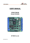
3.2 BOARD LAYOUT
Figure: STAR iCON100 Control Board Layout
DIP S/W (BOARD ID S/W, Initialize S/W)
This BOARD ID S/W(Pin 1 ~ 5) is for communication ID setting of iCON100 control board.
This Initialize S/W(Pin 8) is to initialize and erase all user data from the memory.
+12V and GND (Main Power)
This is main power connection of control board and iCON100 is working at DC12V,
max. 350mA current. (Excluding lock current)
TTL #1 ~ TTL #2
These are 2 TTL output ports at DC5V TTL level, max. 20mA current.
The normal logical state of TTL output is Low (DC 0V) and activates to High (DC 5V).
10
20030516
Manual
User’s