1
User’s Manual
Facial & Proximity / PIN
Time & Attendance
Access Controller
Table of Contents
Welcome to IDTECK............................................................................................................................... 5
Copyrights/ Certifications/ Trademarks/ Disclaimer ................................................................................ 5
Cautions ................................................................................................................................................. 6
FOR FACE006 / FACE007 ....................................................................................................................12
1. Overview............................................................................................................................................17
Features .............................................................................................................................................17
Components .......................................................................................................................................18
2. Specifications ....................................................................................................................................21
3. Comparison Table..............................................................................................................................23
4. Installation .........................................................................................................................................23
4.1 Before Installation.........................................................................................................................23
4.2 Installing the FACE006/007 ..........................................................................................................25
4.2.1 Attaching the wall mount .......................................................................................................25
4.2.2 Setting the Jumper Switch for Battery Backup......................................................................26
4.2.3 Initializing the FACE006/007.................................................................................................26
4.2.4 Attaching the FACE006/007 to the Wall Mount .....................................................................29
4.3 Communication Protocols and Cable Selection............................................................................29
4.3.1 Cable Connection .................................................................................................................30
4.3.2 RS-232..................................................................................................................................33
4.3.3 RS-422..................................................................................................................................34
4.3.4 Modem..................................................................................................................................35
4.3.5 TCP/IP ..................................................................................................................................38
4.4 Connecting External Devices .......................................................................................................39
4.4.1 Power Supply........................................................................................................................40
4.4.2 Door Sensor..........................................................................................................................42
4.4.3 Door Lock .............................................................................................................................42
4.4.4 Exit Button ............................................................................................................................44
4.4.5 External Reader....................................................................................................................45
4.4.6 Alarm Device.........................................................................................................................46
4.4.7 External Input Device............................................................................................................47
4.5 Checking Basic Operation ............................................................................................................48
4.5.1 Checking Power Supply........................................................................................................48
5. General Settings (Mode Selection) ....................................................................................................49
5.1 ID..................................................................................................................................................50
5.1.1 Registering an ID ..................................................................................................................50
5.1.2 Deleting an ID .......................................................................................................................52
2
MAMFAC7HE10
5.2 Time .............................................................................................................................................53
5.2.1 Setting Time..........................................................................................................................53
5.3 Communication ............................................................................................................................53
5.3.1 Baud Rate.............................................................................................................................53
5.3.2 COMM ID SETTING .............................................................................................................54
6. Advanced Settings.............................................................................................................................55
6.1 ID Management............................................................................................................................55
6.1.1 Changing the Master ID ........................................................................................................55
6.1.2 Managing and Setting IDs.....................................................................................................58
6.2 Access Control .............................................................................................................................66
6.2.1 Access Mode (MODE SELECTION) .....................................................................................66
6.2.2 Antipassback (APB SETUP) .................................................................................................67
6.2.3 Duress Mode (DURESS MODE SET)...................................................................................68
6.3 System Configuration ...................................................................................................................69
6.3.1 Communication.....................................................................................................................69
6.3.2 Keypad (RF_PIN_INPUT).....................................................................................................70
6.3.3 Face......................................................................................................................................71
6.3.4 Event.....................................................................................................................................72
6.3.5 Authorization/Error Display (LCD DISPLAY) .........................................................................73
6.4 Schedule Management.................................................................................................................74
6.4.1 Time Schedule ......................................................................................................................74
6.4.2 Holiday..................................................................................................................................76
6.4.3 Output Time ..........................................................................................................................77
6.4.4 Access Mode by Schedule (MODE INDEX)..........................................................................81
6.4.5 Voice Mode by Schedule (VOICE INDEX) ............................................................................81
7. Test and Info Display .........................................................................................................................82
7.1 Test...............................................................................................................................................82
7.1.1 LCD Test ...............................................................................................................................82
7.1.2 Keypad Test ..........................................................................................................................82
7.1.3 Communication Test .............................................................................................................83
7.1.4 Reader Test...........................................................................................................................83
7.1.5 Input Port Test.......................................................................................................................84
7.1.6 Output Port Test ....................................................................................................................84
7.1.7 Data Memory Test.................................................................................................................85
7.1.8 Door Test ..............................................................................................................................86
7.1.9 Alarm Test .............................................................................................................................86
7.2 Info Display...................................................................................................................................86
7.2.1 Firmware Version (F/W VERSION) .......................................................................................87
7.2.2 The Number of Events (EVENT COUNT) .............................................................................87
Troubleshooting .....................................................................................................................................88
3
MAMFAC7HE10
[LCD Display] .....................................................................................................................................88
[Switching to Mode Selection] ............................................................................................................89
[Changing the Settings] ......................................................................................................................90
[Registering a face] ............................................................................................................................97
[Communication] ................................................................................................................................99
[External Device] ..............................................................................................................................100
[Door Lock].......................................................................................................................................102
[Keypad] ...........................................................................................................................................104
Glossary ..............................................................................................................................................106
Customer Support ...............................................................................................................................120
Warranty ..............................................................................................................................................121
Return Policy .......................................................................................................................................121
Ownership and Risks...........................................................................................................................122
MAMFAC7HE10
4
Welcome to IDTECK
Thank you for choosing IDTECK.
The FACE006/007 Series products (FACE007, FACE007SR, FACE007P, IP- FACE007) are worldrenowned state-of-the-art access control systems that deliver reliability and simplicity where higher
levels of security are required. We are confident that the FACE006/007 will be an effective security
solution for access control as well as for protection of life and property.
We will continue our efforts to build faster and more reliable service networks and develop more
advanced products for our customers.
IDTECK Co., Ltd.
Copyrights/ Certifications/ Trademarks/ Disclaimer
Copyrights
● Patents, trademarks, copyrights and other intellectual property related to the product and the user's
manual are owned by IDTECK and protected under relevant laws and regulations. The
specifications and the exterior of the product and the content of the user's manual may not be
duplicated or reproduced in any form or by any means without prior permission from IDTECK. Any
duplication or reproduction of all or part of the product or the user's manual will be subject to legal
proceedings under the relevant laws and regulations.
Copyright 2006 IDTECK Co., Ltd. All Rights Reserved.
Certifications
IDTECK FACE006/007 obtains CE, FACC, UL and MIC certifications from major state-run
organization in foreign countries.
Conformity European (CE)
Imposes mandatory safety standards in the EU and proves that products meet
basic safety conditions.
Federal Communication Committee (FCC)
Imposes mandatory safety standards for electromagnetic waves in the US.
Regulates unnecessary electromagnetic waves emitted from major electronic
and electrical products as a part of their efforts to ensure efficient use and
management of electromagnetic wave resources.
Underwriters Laboratory (UL)
Non-mandatory certification representing electrical safety.
Ministry of Information and Communication (MIC)
The Electromagnetic Compatibility Registration System was established by
the Korean MIC to prevent communication errors caused by undesirable
electromagnetic waves created by electrical and electronic devices, and to
prevent industrial hazards caused by product malfunction. It further aims to
protect the domestic electromagnetic environment and enhance the
competitive edge of Korean products in world markets by actively dealing with
the protectionist policies of the advanced countries.
MAMFAC7HE10
5
Trademarks
The
logos are trademarks of IDTECK Co., Ltd.
Disclaimer
● The manufacturers, importers and agents of this product bear no responsibility for any accidental
damage including bodily injury or other losses resulting from inappropriate use or manipulation
of this product.
● The information contained in the user's manual is based on the current version of the product.
IDTECK continues to add new features to the product for user convenience and will continue to
apply new technologies to the product in the future. Accordingly, IDTECK reserves the right to
change the exterior and specifications of the product for enhancement of quality and
performance without prior notice.
Cautions
Users should familiarize themselves with the following cautions before installing and using the
product. The cautions listed below contain important information for the protection of human life
and product safety. These cautions are divided into three categories of danger, warning and
caution depending on their importance. Please be aware that IDTECK shall not bear any
responsibility for bodily injury or product damage that may be caused by ignoring these cautions.
Incorrect handling of the product may result in major injury or death.
Danger
Incorrect handling of the product may result in minor or major injury.
Warning
Incorrect handling of the product may result in minor injury or property
damage.
Caution
MAMFAC7HE10
6
Danger
Operating Voltage
Do not repair by yourself
Only the operating voltage (DC 12V fixed /
300mA or above) indicated in this manual
should be used.
Otherwise, it may cause fire, electric
shock or product damage.
Do not disassemble, repair or modify the
product by yourself. Doing so may cause
fire, electric shock, product malfunction or
shortened product life.
Grounding
Check for anomalies
Make sure that the product is properly
grounded. If not, it may cause fire, electric
shock or product damage.
If the product emits any smoke, smell or
noise, or a foreign body or liquid gets into
the product, turn the power off
immediately and remove the power plug
from the outlet. Otherwise, it may cause
fire, electric shock or product damage.
MAMFAC7HE10
7
Handling the power cord
Handling the power plug
Do not place a heavy object on top of the
Do not hand the power plug with wet
power cord. Do not cut, bend, twist, pull or
heat it. If damaged, it may cause fire or
electric shock.
hands. Doing so may result in electric
MAMFAC7HE10
shock.
8
Warning
Avoid passageways
The power cord and connection cables
should not be installed across a passageway.
They may trip people up or cause product
damage.
Do not replace cables by yourself
The cables should be replaced by a
qualified technician only. Inappropriate
cable replacement may lead to fire,
electric shock or malfunctioning of the
product.
Avoid liquid or moisture
Avoid heat
Make sure that the product does not get
wet with water (rain) or drinks. If the
product gets wet, it may lead to irrevocable
product damage.
Do not heat the product. Otherwise, it may
cause fire or product damage.
MAMFAC7HE10
9
Caution
Avoid dusty places
Do not install the product in a dusty place.
Avoid vibration, noise, dust and
other electromagnetic devices
Do not install the product in places near a
motor, mechanical noise, vibration or dust,
or near another electromagnetic device. It
may lead to malfunctioning of the product.
Cleaning the product
Clean the product gently with a dry cloth
or towel. Do not use chemicals such as
benzene, thinner or acetone as they may
cause discoloration or deterioration of the
product.
MAMFAC7HE10
10
Do not operate under the following conditions:
Using the product under the following conditions may lead to malfunctioning of the product.
● Operating Temperature: -15° to +40°C (+5° to +104°F)
● Operating Humidity: 10% to 90% relative humidity non-condensing
● Dusty places
● Direct sunlight
● Places exposed to rain
● Near other communication or power cabling
● Near flammables
Installation and Operation
● Make sure that external devices are connected to the product before power is supplied.
● Install the product on a secure surface.
● Make sure that other cabling does not interfere the product or its cables.
Otherwise, it may lead to malfunctioning of the product.
● The product should be installed only by a qualified technician.
● When installing several product units, make sure to keep a sufficient distance between units.
● Use only accessories approved by IDTECK.
● If voltage fluctuation occurs due to a natural disaster or power outage, the product may
malfunction.
Product Handling
● Do not let children play with the product. Otherwise, it may lead to product damage or
malfunctioning.
● Do not subject the installed product to a strong impact. Otherwise, it may result in product
damage or malfunctioning.
● Make sure to set the battery backup DIP switch on the back of the product to ON and
initialize the product before use. If the product is used with the switch set to OFF, all the
data stored in the product will be lost during power outage or shutdown.
● Make sure to remove any dirt from face before placing one on the facial recognition camera
for authorization.
● Do not press the keypad with a sharp object - use only your face. Otherwise, the keypad
may be damaged.
● Do not clean the product while it is ON. Doing so may cause product damage or
malfunctioning.
● Once the product is installed, it is recommended to change the master ID and password as
often as possible.
● If the product is considered not repairable or has reached the end of its life, make sure to
dispose it in accordance with the relevant electronic device disposal regulations.
MAMFAC7HE10
11
FOR FACE006 / FACE007
1. Place the bottom of FACE reader at height of 5.3”(150~160cm).
2. To obtain a better photo image and higher accuracy during face reader enrollment and
verification, please stand directly in front of face reader at an arm’s length from the unit’s front
cover. Continue looking at the camera, following the audible instructions from the unit, until
either enrollment or verification is completed.
3. We recommend using an LCD monitor to ensure that the position of face being enrolled is
centered in the camera’s view. A better quality image will increase the accuracy of the reader.
4. To get a fast verification and to increase the accuracy ratio, please try to maintain a similar
facial expression to the one used during enrollment.
5. Please keep a constant and good lighting condition to avoid shade on the face.
6. Make sure the backdrop wall is clean and of a solid color.
(Please remove any picture frames hanging on the wall)
7. Keep your face still, looking directly into the camera, and do not nod up and down or move
your face right and left, otherwise the enrollment and verification may fail.
8. Please keep lighting condition (i.e. brightness, light direction) consistent to that used during the
enrollment and verification process.
9. Too much back light will produce a shadow on the face and light direction from a side angle
may reflect a shadow to the other side of the face. In these instances registration or
verification may fail.
10. Keep constant lighting environment for enrollment and verification at all times. The system
operation at a given location may be affected by changes in the level and direction of sun light
that fall on the reader through a window at different times of the day (Morning, Afternoon,
Sunset, Night).
11. While eyeglasses are OK for use with the system, do not enroll or attempt verification while
wearing sunglasses.
MAMFAC7HE10
12
Correct Position
You should stand and look on the central position of camera for facial registration.
Completely standing right at a distance of arm will provide the best performance.
MAMFAC7HE10
13
Incorrect Position
Avoid standing and looking as shown below.
A. Face Distance
Recommendation
The whole of 40 to 60% screen size
At 60 to 80cm distance
(at a distance of arm)
too close
too far away
B. Eye Condition
Recommendation
Show you looking directly at the camera.
Show your eyes open and clearly visible.
close eyes
looking away
C. Face Tilt
raise head
lower head
stand sideways
tilt face
Recommendation
•
Show you facing square on to the camera, not looking over one shoulder
(portrait style) or tilted, and showing both edges of your face clearly.
MAMFAC7HE10
14
D. Light Condition
shadows
across face
backlight
too light
too dark
Recommendation
•
•
•
Be color neutral. / Have appropriate brightness and contrast.
Be taken with a plain light-colored background.
Be taken with uniform lighting and not show shadows or flash reflections on your face
and no red eye.
•
Luminous intensity of installation area maintains from 200 Lux to 400 Lux on indoors.
E. Glasses
frame too heavy
frame
covering eyes
reflection
on lenses
dark tinted lenses
Recommendation
If you wear glasses:
•
Show your eyes clearly with no flash reflection off the glasses, and no tinted lenses.
(If possible, avoid heavy frames – wear lighter framed glasses if you have them)
•
Make sure that the frames do not cover any part of your eyes.
MAMFAC7HE10
15
F. Face Expression
Recommendation
Look at the camera with a neutral
expression and your mouth closed.
smiling
mouth open
G. Head Coverings
Recommendation
Are not permitted except for religious
reasons, but your facial features from
bottom of chin to top of forehead and both
edges of your face must be clearly shown.
wearing a hat
hat covering face
H. Hair Style
Recommendation
No hair across your eyes.
hair
covering eyes
hair
covering face
I. Lens Focus & Face Position
Recommendation
Look at the camera with a neutral
expression.
No motion
motion blur
MAMFAC7HE10
cut face
16
1. Overview
Features
Higher Level of Security and Higher Safety
● This product is equipped with a facial recognition module and a proximity RF reader for
enhanced security and safety in access control.
● In case you are forced to open a door against your will, the product in Duress mode assures
your safety by reporting the situation to a system administrator.
● If the product is disassembled by force, the tamper switch is enabled, activating an alarm
sound.
Facial Registration Management
● By default, you can register up to 10,000 facial templates in the system.
Effective Management
● The Time and Holiday Scheduling function ensures efficient control over user access and
attendance.
● The Antipassback (APB) function ensures more efficient access control.
● In addition to independent data management, efficient data management is provided via a PC
connection.
Various Access Control Method
● The product provides three access modes: RF ONLY, RF + FACE (P/W) and RF+ P/W +
FACE. You can use any of these access modes to meet your specific access control needs.
Various PC Connections
● The product supports various computer connections: 1:1 connection via RS-232, 1:N
connection via RS-422 and 1:N connection via TCP/IP.
In case of FACE007, you can connect up to 32 units of the product to a single PC.
In case of FACE006, you can connect up to 256 units of the product to a single PC too.
Connectivity with Various External Devices
● The IDTECK FACE007 has four input ports that can accommodate external devices such as
an exit button, a door sensor or an external input device, and four Form-C relay output ports
that can accommodate a door lock and an alarm device.
● This IDTECK FACE006 can transfer information about user to various ways that Wiegand or
ABA Track II etc. So it is easy to use area which is using existing proximity card system.
Ease of Use
● Using its built-in test function, you can test the product to check for any anomalies.
MAMFAC7HE10
17
● By default, you can store up to 20,000 events in the product.
Summary
125KHz Proximity / PIN and Facial Recognition
Dual Function for Access Control and Time & Attendance
10,000 Facial Users / 20,000 Event Buffers
1:1 Verification storable 4 Facial Templates
Various operating mode
Standalone / Network Communication via RS232 / RS422 / RS485 (Max.32ch),
TCP/IP (External LAN Converter required)
1ea of External Reader Port for Antipassback Function:
26bit Wiegand and 4 / 8bit Burst for PIN
1ea of External Reader Port (FACE006EX):
26/34bit Wiegand, 4/8bit Burst for PIN and ABA Track II
26bit Wiegand and ABA Track II Output Format (FACE006/P)
Independent 4 Inputs and 4 Outputs including 4ea of 2 Form-C Relay Outputs
Video Output with NTSC Signal, Voice Output
Tamper Switch
Rainbow Color LED Indicator for Image Capture
Options:
Video Output with PAL Signal (Coming soon)
Compatible Software: STARWATCH DUAL PRO I / II
STARWATCH iTDC PRO I / II (FACE006 only)
Components
The product package contains the FACE007 or FACE006, a wall mount, user's manual, two
diodes, five O-rings, an RMA Request Form, bolts and anchor bolts. Upon unpacking, make sure
that all of the items listed are contained in the package.
If any of the items are missing, please contact IDTECK.
Optional items are sold separately. To purchase an optional item, please contact IDTECK.
◈ Basic Items
Main Unit
(1ea)
MAMFAC7HE10
Wall Mount
(1ea)
User’s Manual
(1copy)
Cable & Diode
(4ea & 4ea)
18
RMA Request Form
(1copy)
Screws (3.5X4.0mm)
(4ea)
Screws (3.5X12mm)
(4ea)
Anchor Bolts
(4ea)
*External Reader
RFK101
Door Sensor
DCT-100 (1set)
Exit Button
EB20/10
◈ Optional Items
Power Supply
ID40WA
* A Wiegand 26-bit card reader can be used as an external reader.
•
CNP-200A
CNP-200A
Converter
•
RS-422 Cable
RS-232 Cable
Door Lock
IEB-300
Template Sheet for
Deadbolt Lock Body
MAMFAC7HE10
7-Pin Cable
for IEB-300
Partial Fixing Plate
for IEB-300
Full Fixing Plate
For IEB-300
Fixing Screws
for IEB-300
19
•
•
Access Card
Key Tag
RF ID Card
Modem
* External Modem
* When installing a modem, make sure to use an external modem approved by IDTECK. When
connecting an external device to a communication device, it is recommended to use the
devices introduced in this manual only. For more information on compatible external modems,
please contact IDTECK.
•
NetEye 1000SA
NetEye 1000SA
Note
MAMFAC7HE10
RS-422 Cable
for NetEye 1000S
IPA-100
for NetEye Adapter
These components may be changed without prior notice for enhancement of
product performance and quality.
20
2. Specifications
Model
FACE007
FACE007P
32bit DSP, 8bit and 16bit Microprocessor
CPU
Memory
Facial
Module
(FRM10K)
Controller
Program
Memory
Data Memory
Program
Memory
Data Memory
Facial User
Facial Template Size
Event Buffer
Read Range
Passive Type
Active Type
Reading Time (Card)
Verification Time
Power / Current
External Reader Port
Communication
Baud Rate
Input Port
Output Port
Video Signal
CCD Camera
LCD
Keypad
LED Indicator / Beeper
Voice
Operating
Temperature
Facial Module
LCD
Controller
RF Reader
Operating Humidity
Color / Material
Weight / Dimension (W x H x T)
MAMFAC7HE10
32KByte EPROM
16MByte Flash Memory
256KByte Flash Memory
512KByte SRAM (Battery back up)
10,000 Facial Users
730Byte (3DES)
20,000 Event Buffers
IDK50 / IMC125:
Up to 2 inch (5cm)
IDC80 / IDC170:
PIN only
Up to 4 inch (10cm)
IDA150 / IDA200 compatible
30ms
Less than 0.5sec.
DC 12V / Max.1A
1ea (26bit Wiegand and 4/8bit Burst for PIN)
for Antipassback
RS232 / RS422 / RS485 (Max.32ch)
TCP/IP (External LAN Converter required)
9,600bps (default)
/ 4,800bps, 19,200bps, 38,400bps, 57,600bps
and 115,200bps (selectable)
4ea (Exit Button, Door Sensor, Aux#1, Aux#2)
4ea (FORM-C Relay Output (COM, NO, NC)
/ DC12V~18V, Rating Max.2A)
1ea (Video Output / Composite 1Vp-p 75 Ohm unbalanced)
NTSC Signal (default), PAL Signal (optional)
230K / 430K pixels (NTSC Signal)
Graphic LCD (122 x 32 dots)
/ 2.62” x 0.55” (60.5mm x 18.5mm) Screen
16 Key Numeric Keypad
1ea of Rainbow Color LED Indicator for Image Capture,
3 Array LED Indicators (Red, Green and Yellow) / Piezo Buzzer
Yes
0° to +40°C (-32° to +104°F)
-20° to +70°C (-4° to +158°F)
-15° to +40°C (+5° to +104°F)
-35° to + 65°C (-31° to +149°F)
10% to 90% relative humidity non-condensing
Dark Pearl Gray / Polycarbonate
600g (1.32lbs) / 5.1” x 7” x 1.9” (130mm x 187mm x 54mm)
21
Model
FACE006
FACE006P
FACE006EX
32bit DSP, 8bit and 16bit Microprocessor
CPU
Facial
Module
(FRM10K)
Memory
Controller
Program
Memory
Data
Memory
Program
Memory
Data
Memory
32KByte EPROM
16MByte Flash Memory
256KByte Flash Memory
512KByte SRAM (Battery back up)
Facial User
Facial Template Size
Read Range
10,000 Facial Users
730Byte (3DES)
Passive
Type
Active Type
Reading Time (Card)
Verification Time
Power / Current
Depending on
External Readers
1ea
(26/34bit Wiegand,
N/A
N/A
4/8bit Burst for PIN,
ABA Track II)
RS232 / RS422 / RS485 (Max.256ch)
TCP/IP (External LAN Converter required)
9600bps (default)
/ 4,800bps, 19,200bps, 38,400bps, 57,600bps
and 115,200bps (selectable)
2ea (Error-Input, OK-Input)
2ea (Error-Output, OK-Output (Open Collector Output))
1ea (Video Output / Composite 1Vp-p 75 Ohm unbalanced)
26bit Wiegand, ABA Track II
NTSC Signal(default), PAL Signal (optional)
230K / 430K pixels (NTSC Signal)
Graphic LCD (122 x 32 dots) /
2.62” X 0.55” (60.5mm X 18.5mm) Screen
16 Key Numeric Keypad
1ea of Rainbow Color LED Indicator for Image Capture,
3 Array LED Indicators (Red, Green and Yellow) / Piezo Buzzer
Yes
Communication
Baud Rate
Input Port
Output Port
Output Format
Video Signal
CCD Camera
LCD
Keypad
LED Indicator / Beeper
Voice
Facial
Module
LCD
Controller
RF Reader
Operating Humidity
Color / Material
Weight / Dimension (W x H x T)
MAMFAC7HE10
PIN only
Less than 0.5sec.
DC 12V / Max.1A
External Reader Port
Operating
Temperature
IDK5 / IMC125:
Up to 2 inch (5cm)
IDC80 / IDC170:
Up to 4 inch(10cm)
IDA150 / IDA200
compatible
30ms
0° to +40°C (-32° to +104°F)
-20° to +70°C (-4° to +158°F)
-15° to +40°C (+5° to +104°F)
-35° to + 65°C (-31° to +149°F)
10% to 90% relative humidity non-condensing
Dark Pearl Gray / Polycarbonate
600g (1.32lbs) / 5.1” x 7” x 1.9” (130mm x 187mm x 54mm)
22
Model
CPU
Memory
Monitor Program Memory
Data Memory
Facial User
Capture Image Size
Verification Time
Communication
Baud Rate
Power / Current
CCD Camera
Operating Temperature
Operating Humidity
Weight / Dimension (W x H)
FRM10K (Facial Module)
32bit DSP
32KByte EPROM
16MByte Flash Memory
10,000 Facial Users
480 X 640 pixels
Less than 0.5sec.
RS232
9,600bps (default)
/ 14,400bps, 19,200bps, 38,400bps, 57,600bps and
115,200bps (selectable)
DC 5V / Max.500mA
230K/430K pixels (NTSC Signal)
0° to +40°C (-32° to +104°F)
10% to 90% relative humidity non-condensing
30g (0.07lbs) / 3.7” x 2.1” (95mm x 55mm)
3. Comparison Table
FACE007
FACE007P
FACE006
FACE006P
FACE006EX
Built-in 125KHz (4”) Proximity Reader
RF(PIN) only / RF(PIN)+ Face
RF(PIN)+P/W (4digit) / RF (PIN)+P/W+ Face
PIN (4~8digit) only / PIN + Face
PIN+ P/W (4digit) / PIN + P/W (4digit)+ Face
Built-in 125KHz (4”) RF Reader
RF (PIN) only / RF (PIN)+ Face
RF (PIN)+ P/W (4digit) / RF (PIN)+ P/W (4digit)+ Face
PIN (4~8digit) only / PIN + Face
PIN+ P/W (4digit) / PIN + P/W (4digit) + Face
Built-in External Reader Port
RF (PIN) only / RF (PIN)+ Face
RF (PIN)+ P/W (4digit) / RF (PIN)+ P/W (4digit)+ Face
4. Installation
This chapter provides basic information on installation of the FACE006/007. It describes how to
install the FACE006/007, how to connect communication cables and external devices, and how to
check basic operation of the product.
4.1 Before Installation
This section provides the basic information needed for successful installation of FACE006/007.
Part Names
The FACE006/007 consists of front and rear panels and a rear fixing plate.
MAMFAC7HE10
23
[1] Front Panel
CCD Camera ②
Speaker ③
① Rainbow LED
Graphic LCD ④
Green LED ⑥
⑦ Yellow LED
Red LED ⑤
⑧ Keypad
※ Red LED for power
Green LED for normal verification
Yellow LED for alarm
Keypad for PIN and Reader
[2] Rear Panel
① Rear Pin Hole
Connector ②
③ Battery Backup
DIP Switch
④ Tamper Switch
Rear Pin Hole ⑤
Note
MAMFAC7HE10
For more information on the battery backup DIP switch, see “Setting the
battery backup DIP switch” on page 26.
24
[3] Wall Mount
① Wall Mount Latch
6-32 Screws Hole ②
③ Tamper Switch Bolt
Screws Hole ④
4.2 Installing the FACE006/007
The FACE006/007 can be installed as follows:
① Attach the wall mount to the wall where the FACE006/007 will be installed.
② Set the DIP switch for battery back up to ON, supply power, and then start initialization of
the FACE006/007. (See “Initialization via Mode Selection” on page 28.)
③ Attach the FACE006/007 to the wall mount.
4.2.1 Attaching the wall mount
Once the wiring is completed, offer the wall mount of the FACE006/007 up to a pillar or
wall. The wall mount is provided with the FACE006/007 at the time of purchase and can
be attached as follows:
① First, cut the actual-sized template sheet for the wall mount out of the user's manual
with scissors or a blade, and attach it to the desired location with adhesive.
② Drill six 6-32 screw holes and a 2.36" connection cable hole through the template sheet.
③ Firmly attach the wall mount onto the template sheet with six 6-32 screws hole.
Note
● Alternatively, you can install the wall mount directly into an outlet housing
without using the template sheet provided.
● The template sheet for the wall mount is provided in the last page
(page 140) of the user's manual.
• 6-32 screw hole indicates diameter and length for the screw is
6mm x 32mm.
MAMFAC7HE10
25
4.2.2 Setting the Jumper Switch for Battery Backup
The FACE006/007’s battery connection switch is to prevent discharge of electricity.
Battery jumper switch is set in a state of cutoff when taking goods out of the manufactory.
But if it is reserved existing data of FACE006/007 at discharge of electricity, you should
make battery connection switch to connective condition before installing FACE006/007.
4.2.3 Initializing the FACE006/007
There are two ways to initialize the FACE006/007: pre-installation and post-installation
initialization.
Caution
When installing the product for the first time, make sure to perform
pre-installation initialization.
[1] Pre-installation initialization
Before installing the FACE006/007, its built-in memory must be initialized.
To initialize the FACE006/007, connect it to a power supply as follows:
Caution
If you fall to do this, the FACE006/007 may malfunction because of the
contents stored in the memory.
① Connect between the wires used in initialization among the rear panel cables in the
state of switching off the FACE006/007.
FACE006/007 (Rear Panel Connection Cable)
1
White wire + Blue wire with white stripe
2
Green wire + Brown wire with white stripe
MAMFAC7HE10
26
② Connect the FACE006/007 to the power supply. For connecting information,
see “Power Supply” on page 40.
③
Supply power to the FACE006/007.
-“System Initialize” will appear on the LCD of the FACE006/007.
④
Press key “1”.
- “DELETE ALL DATA, WAIT..” will appear on the LCD.
- “System Initializing!” will appear on the LCD.
⑤ After the FACE006/007 is initialized, shut down the power to it.
⑥
If “System is Clear, Remove Wires!!” appears on the LCD in
about 10 seconds, the FACE006/007 has been successfully
initialized.
⑦ Remove wiring between white and blue with white stripe wires of the FACE006/007
rear panel connection cable.
Repeat the removal of a wiring between green and brown with white stripe wires of the
FACE006/007 rear panel connection cable.
MAMFAC7HE10
27
⑧
If “SYS INITIALIZE” appears on the LCD in about 10 seconds,
the FACE006/007 has been successfully initialized.
⑨
Press the ESC key repeatedly until the initial screen appears.
[2] Post-installation initialization
If the Master ID and password are known, the FACE006/007 can be initialized simply by
choosing the SYS INITIALIZE option in Mode Selection.
Caution
Note
If the Master ID and password have been changed, you should go through a
new authorization process with the changed Master ID, password and your
face in order to access Mode Selection.
For more information on Mode Selection, see “General Settings (Mode
Selection)” on page 49.
①
Press “0” key eight times and then press the “ENT” key.
②
Enter “3141” as the master password.
Note
③
Press “0” eight times for FACE006/007, FACE006/007P, and IP-FACE006
/007, and ten times for FACE006/007SR.
Switch to Mode Selection.
- “MODE SELECTION” will appear on the LCD.
④
Press “4” or “6” repeatedly until “SYS INITIALIZE”
Appears on the LCD and then press the ENT key.
- “System Initialize” will appear on the LCD.
⑤
Press key “1”.
- “DELETE ALL DATA, WAIT..” will appear on the LCD.
- “System Initializing…” will appear on the LCD.
⑥
If “SYS INITIALIZE” appears on the LCD in about 10 seconds,
the FACE006/007 has been successfully initialized.
⑦
Press the ESC key repeatedly until the initial screen appears.
MAMFAC7HE10
28
4.2.4 Attaching the FACE006/007 to the Wall Mount
This section describes how to attach the FACE006/007 to the Wall Mount.
Fix six screws on each 6-32 screw hole in the Wall Mount, and attach the FACE006/007 to
the Wall Mount. When the installation is completed, test the FACE006/007 in Mode Selection.
Removing the FACE006/007 from the Wall Mount by force may damage a tamper switch
clamp in the Wall Mount, in which case the Wall Mount would need to be replaced.
Note
Caution
All the required connections between the FACE006/007 and external
devices must be made before attaching the FACE006/007 to the Wall
Mount. For more information on cable connection, see “Communication
Protocols and Cable Selection” on page 29 and “Connecting External
Devices” on page 39.
After all cables are connected, make sure to perform complete testing on
the functionality of the FACE006/007 before attaching it to the Wall Mount.
Make sure that the DIP switch for battery backup is set to ON.
For more information on testing, see “Test and Info Display” on page 82.
4.3 Communication Protocols and Cable Selection
The FACE006/007 supports four different communication methods for communication with a
computer: RS-232, RS-422, modem and TCP/IP. Each of these communication methods has
different cabling requirements. Since cabling requirements may vary depending on installation
environment, you should always check your own installation environment before choosing a
communication method.
Caution
Power should be supplied only when all of the required connections
between the FACE006/007 and external devices have been properly made.
The following table shows specific requirements for each of the communication methods
supported:
Max.
Range
Recommended
Device
MAMFAC7HE10
RS-232
RS-422
Modem
TCP/IP
15m
1200m
Indefinite
RS-232
9pin Connector
CNP-200A
Converter
RS-232/422
9pin Connectors
1per each
RS-485
INC300
Converter
RS-232/485
External Modem NetEye1000SA
Converter,
x2
Telephone Cable LAN Cable,
X2
RS232:
9-pin Connector
RS-232:
25pin & 9-25pin
RS-422:
Connectors
9-pin Connector
29
Communication
Type
(Computer:
FACE006/007)
Note
1:1
9pin Connectors
1 per each
RS-422:
CNP-200A
Converter, 9pin,
25pin & 9-25pin
Connectors
1:N (RS-422)
1:N (RS-422)
1:N (RS-422)
The communication range may decrease depending on installation
environment.
4.3.1 Cable Connection
This section describes the cable configuration, cable colors, recommended cables
and transmission range required for communication between the FACE006/007 and external
devices.
[1] Cable Configuration
When connecting the FACE006/007 to an external device, make sure to use the cables
recommended in this manual.
The following diagram shows the cable configuration required for the FACE006/007.
The alphabetical letters in each communication path represent the recommended cable
types. For more information on the recommended cable types, see “Recommended Cables
and Their Transmission Range” on page 31.
MAMFAC7HE10
30
[2] Recommended Cables and Their Transmission Range
Make sure to check the recommended cable for each external device before connecting it to
the FACE006/007. The following table shows recommended cable types for each device in
details:
AÆB
ⓐ
ⓑ
ⓒ
DC Power Supply
Æ FACE006/007
External Reader
Æ FACE006/007
Input Device
Æ FACE006/007
Max. Range
Belden #9409, 18 AWG
2 conductor, unshielded
Max.30m
Belden #9512, 22 AWG
4 conductor, shielded
Belden #9514, 22 AWG
8 conductor, shielded
Belden #9512, 22 AWG
4 conductor, shielded
Max.150m
Max.300m
Belden #9514, 22 AWG
8 conductor, shielded
ⓓ
Exit Lock, Alarm Device
Æ FACE006/007
ⓔ
Converter Æ Computer
(Use RS232 Cable)
ⓕ
Recommended Cable
Belden #9409, 18AWG
2 conductor, unshielded
Max.300m
Belden #9829, 24 AWG
2-twisted pair, shielded
Max.15m
FACE006/007
Æ FACE006/007
FACE006/007
Æ Converter
(Use RS422 Cable)
Belden #9830, 24 AWG
3-twisted pair, shielded
FACE006/007
Æ FACE006/007,
FACE006/007
Æ Converter
(Use RS485 Cable)
Belden #9829, 24 AWG
2-twisted pair, shielded
Max.1,200m
* When connecting a reader to the FACE006/007 using a cable, the capacity of the cable
should be greater than the maximum current consumed by the reader.
Note
• A -> B represents the connection between the FACE006/007 and an
external device. The letters “A” and “B” respectively represent a device
name.
[3] Cable Colors
The following table shows an individual cable color corresponding to each of the FACE006/
007 ports.
MAMFAC7HE10
31
Port
FACE007
FACE006
POWER
Main Power
RED
RED
(DC 12V)
Power Ground
BLACK
BLACK
WIEGAND DATA OUTPUT
Wiegand 0
GREEN
GREEN
Wiegand 1
WHITE
WHITE
ABA TRACK II DATA OUTPUT
ABA Track II Data
GREEN
GREEN
ABA Track II
WHITE
WHITE
Clock
ABA Track II CLS
ORANGE
ORANGE
RS232 INTERFACE
RS-232 RX
RED + WHITE
RED + WHITE
RS-232 TX
BLACK + WHITE BLACK + WHITE
RS-232 Ground
BLACK
BLACK
RS422 INTERFACE
RS-422 RX+
BROWN
BROWN
RS-422 RXBLUE
BLUE
RS-422 TX+
GRAY
GRAY
RS-422 TXYELLOW
YELLOW
DOOR RELAY OUTPUT (FACE007)
NC
GREEN + RED
COM
WHITE + RED
NO
ORANGE + RED
ALARM RELAY OUTPUT (FACE007)
NC
BROWN + RED
COM
BLUE + RED
NO
YELLOW + RED
SUB RELAY 1 OUTPUT (FACE007)
GREEN +
NC
BLACK
COM
WHITE + BLACK
ORANGE +
NO
BLACK
SUB RELAY 2 OUTPUT (FACE007)
BROWN +
NC
BLACK
COM
BLUE + BLACK
YELLOW +
NO
BLACK
INPUT (FACE007)
BROWN +
Exit
WHITE
Door Sensor
BLUE + WHITE
Aux #1
GRAY + WHITE
YELLOW +
Aux #2
WHITE
EXTERNAL READER PORT (FACE007)
Wiegand 0
PINK
Wiegand 1
CYAN
EXTERNAL READER PORT (FACE006EX - WIEGNAD)
Wiegand 0
GRAY + WHITE
MAMFAC7HE10
Connector No.
4
4
4
4
4
4
4
5
5
5
3
3
3
3
1
1
1
1
1
1
1
1
1
1
1
1
2
2
2
2
2
2
2
32
YELLOW +
WHITE
EXTERNAL READER PORT (FACE006EX – ABA TRACK II)
BROWN +
DATA
WHITE
YELLOW +
CLOCK
WHITE
CLS
BLUE + WHITE
TAMPER OUT
TAMPER
VIOLET
VIOLET
CONTROL SIGNAL (FACE006/FACE006EX)
OK OUTPUT
PINK
ERROR OUTPUT
CYAN
OK INPUT
PINK + WHITE
ERROR INPUT
CYAN + WHITE
VIDEO SIGNAL OUTPUT (NTSC)
GREEN +
VIDEO_OUT
GREEN + WHITE
WHITE
VIDEO_GND
BLACK + RED
BLACK + RED
Wiegand 1
2
2
2
2
4
2
2
2
2
6
6
[4]Cable Connector Position
1. CONNECTOR1: Relay Connector (FACE007 ONLY)
2. CONNECTOR2: Input Control Connector
3. CONNECTOR3: RS422 Connector
4. CONNECTOR4: Power, Output (WIK, ABA, Tamper)
5. CONNECTOR5: RS232 Connector
6. CONNECTOR6: Video Output Connector
7. PIN HEADER: Memory Backup Switch
4.3.2 RS-232
The FACE006/007 can be connected to a computer with an RS-232 9-pin connector.
If the connection range exceeds 15m, the FACE006/007 may malfunction.
An RS-232 9-pin connector must be prepared separately.
① Connect an RS-232 9-pin connector to the FACE006/007 as indicated in the following
table.
FACE006/007
RS-232 9-pin Connector
(Rear Panel Connection Cable)
1
TX (Black wire with White stripe)
RX (No.2 Pin)
2
RX (Red wire with White stripe)
TX (No.3 Pin)
3
GND (Black wire)
GND (No.5 Pin)
MAMFAC7HE10
33
② With the cable prepared in step ①, connect an RS-232 9-pin connector to the serial
port of a computer.
4.3.3 RS-422
In this communication method, more than one FACE006/007 can be connected to a computer
with an RS-422 9-pin connector, an RS-232 9-pin connector and a CNP-200A converter.
Please note that the FACE006/007 may malfunction if the connection range exceeds 1,200
meters.
The connection method for an RS-422 connector may vary depending on the type of
converter. The use of a CNP-200A converters, see the user’s manual that comes with the
product.
Note
The maximum transmission range may be reduced depending on the
installation environment.
① Connect an RS-422 9-pin connector to the FACE006/007 as indicated in the following
table.
FACE006/007
RS-422 9-pin Connector
(Rear Panel Connection Cable)
1
Yellow wire(TX-)
Black wire (RX-)
2
Gray wire(TX+)
Blue wire(RX+)
3
Blue wire(RX-)
White wire(TX-)
4
Brown wire(RX+)
Red wire(TX+)
② With the cable*1) prepared in step ①, connect an RS-422 9-pin connector to the RS422 port of a CNP-200A converter.
MAMFAC7HE10
34
③ With an RS-232 cable*2), connect the RS-232 port of the converter to the serial port of
a computer.
4.3.4 Modem
Using a modem, more than one FACE006/007 can be connected to a computer via RS-232
or RS-422 connection for any distance. For information on device requirements for each
connection, see page 32.
9-25 pin connector*) should be manufactured personally and its connection should be differed
depending on your connection type for RS-232 and RS-422. For RS-422 connection, the use
of a CNP-200A converter is recommended by IDTECK. This section describes how to
connect the FACE006/007 to a computer via a modem using a 9-25 pin connector and a
CNP-200A converter. For more information on CNP-200A converters, see the user’s manual
that comes with the product.
Caution
After all cables are connected, make sure to perform complete testing on
the functionality of the FACE006/007 before attaching it to the Wall Mount.
Make sure that the DIP switch for battery backup is set to ON.
For more information on testing, see “Test and Info Display” on page 116.
*) Refer
to picture about how to manufacture a 9-25 pin connector on page 39.
[1] RS-232
① Connect a 25-pin connector*2) for RS-232 to the FACE006/007 as indicated in the
following table.
FACE006/007
25-pin Connector*2) for RS-232
(Rear Panel Connection Cable)
1
Black wire with White stripe (TX)
Pin #3 (RX)
MAMFAC7HE10
35
2
Red wire with White stripe (RX)
Pin #2 (TX)
3
Black wire (GND)
Pin #7 (GND)
② With the cable*2) prepared in step ①, connect a 25-pin connector to the RS-232 to the
25-pin port of a remote modem.
③ With a telephone cable, connect the telephone terminal of the modem to a PSTN outlet.
④ With the 9-25 pin connector manufactured personally, connect the 25-pin connector for
RS-232 of a host modem to the serial port of a computer.
⑤ With a telephone cable, connect the telephone terminal of the modem to a PSTN outlet.
[2] RS-422
① Connect a 9-pin connector*3) for RS-422 to the FACE006/007 as indicated in the
following table.
FACE006/007
25-pin Connector*2) for RS-232
(Rear Panel Connection Cable)
1
Yellow wire (TX-)
Black wire (RX-)
MAMFAC7HE10
36
2
Gray (TX+)
Blue wire (RX+)
3
Blue (RX-)
White (TX-)
② With the cable*3) prepared in step ①, connect a 9-pin connector to the RS-422 to the
RS422 port of a CNP-200A converter.
③ With the 9-25 pin connector manufactured personally, connect the RS-232 port of a
CNP-200A converter to the 25-pin port of a modem.
④ With a telephone connector, connect the telephone terminal of the modem to a PSTN
outlet.
⑤ With the 9-25 pin connector manufactured personally, connect the 25-pin connector of
a host modem to the serial port of a computer.
⑥ With a telephone connector, connect the telephone terminal of the modem to a PSTN
outlet.
MAMFAC7HE10
37
4.3.5 TCP/IP
Using TCP/IP connection, more than one FACE006/007 can be connected to a computer
regardless of the distance. TCP/IP connection requires a LAN cable, a 9-pin connector and a
NetEye1000SA converter is recommended by IDTECK. The DIP switch located in the rear
panel of a NetEye1000SA converter can be used to select the desired communication type
between RS-232 and RS-422.
This section describes how to connect the FACE006/007 to a computer using a
NetEye1000SA converter. For more information on the NetEye1000SA converter, see the
user’s manual that comes with the product.
Caution
There are two types of LAN cables used for TCP/IP connection:
cross and direct. A cross cable is used to connect a NetEye1000SA
converter directly to a computer while a direct cable is used to connect the
converter to a computer via a hub.
[1] RS-232
① Connect a 9-pin connector*1) for RS-232 to the FACE006/007 as indicated in the
following table.
FACE006/007
9-pin Connector*1) for RS-232
(Rear Panel Connection Cable)
1
Black wire with White stripe (TX)
Pin #2 (RX)
2
Red wire with White stripe (RX)
3
Black wire (GND)
Pin #3 (TX)
Pin #5 (GND)
② With the cable*1) prepared in step ①, connect a 9-pin connector to the RS-232 to the
serial port of a NetEye1000SA converter.
③ With a LAN cable*2), connect the LAN port of the NetEye1000SA converter to the LAN
port of a computer.
MAMFAC7HE10
38
[2] RS-422
① Connect a 9-pin connector*1) for RS-422 to the FACE006/007 as indicated in the
following table.
FACE006/007
9-pin Connector*1) for RS-232
(Rear Panel Connection Cable)
1
Yellow wire (TX-)
Black wire (RX-)
2
Gray wire (TX+)
Blue wire (RX+)
3
Blue wire (RX-)
White wire (TX-)
4
Brown (RX+)
Red wire (TX+)
② With the cable*1) prepared in step ①, connect a 9-pin connector to the RS-422 to the
serial port of a NetEye1000SA converter.
③ With a LAN cable*2), connect the LAN port of the NetEye1000SA converter to the LAN
port of a computer.
4.4 Connecting External Devices
Various external devices can be connected to the FACE006/007 to implement required
functionality. External devices should be purchased separately. Make sure to consider installing
FACE006/007 and operational conditions before installing an external device. The following table
lists the type of external devices compatible with the FACE006/007. For information on how to
connect a specific external device, see the user’s manual that comes with the corresponding
device.
MAMFAC7HE10
39
The type of external devices compatible with the FACE006/007.
External Device
Power Supply
Door Lock
Alarm Device
External Reader
Exit Button
Door Sensor
Type
DC 12V / 3A
NO*: Normal Open
Recommended Device
ID40WA
Power Fail Safe
DEB-101A
Power Fail Secure
DEB-101AS
NO TYPE
SIREN LD-96
26Bit Wiegand
(FACE007,IP-FACE007),
4/8Bit Burst
RFK101,
IPK101
34Bit Wiegand (FACE007SR),
4/8Bit Burst
SRK101
NO TYPE
COPS261
NO TYPE (When door is close.)
AMS38B
External (PIR) Sensor NO TYPE
SP-50S(PIR)
Power should be supplied only when all connections between the FACE006/
007 and external devices have been properly made. In particular, do not
connect the DC power cable of the FACE006/007 to the Uninterrupted
Power Supply (UPS) terminal in the power supply. Otherwise, it may lead to
product damage or product malfunction.
Caution
4.4.1 Power Supply
This section describes how to connect a power supply to the FACE006/007. It also provides
information on grounding that is required to prevent electromagnetic interference between
devices. The information in this section is based on power supply model ID40WA.
[1] Connecting to a Power Supply
① Connect the FACE006/007 to a power supply as indicated in the following table:
FACE006/007
9-pin Connector*1) for RS-232
(Rear Panel Connection Cable)
1
Red wire
DC+12V
2
Black wire
DC GND(-)
③ Connect the power outlet cable (220V) to the AC terminal of the power supply.
MAMFAC7HE10
40
[2] Grounding
The residual current flowing through a communication cable may interfere with
communication between the FACE006/007 and an external device.
Proper grounding with a shield wire is required to prevent these electromagnetic
interferences. There are two ways to ground a communication cable with its shield wire:
Earth Ground and Power Ground.
• Grounding should be performed by an experienced technician.
If grounding is not properly performed, it may cause a major accident
such as fire or an explosion.
• Select an appropriate grounding method taking your installation
environment into account.
Caution
• The same grounding method should be used where multiple units are
installed.
• It is recommended to ground each of the installed products separately.
• Only one side of the shielding wire in a communication cable must be
grounded. Otherwise, it may become a primary cause of fire, electric
shock, noise or product damage.
MAMFAC7HE10
41
1. Earth Ground
In Earth Ground, either side of the shield wire in a communication cable is grounded to the
earth. This is the best, but most costly grounding method. If both sides of the shield wire
are grounded to the earth, current flows in the wire due to the difference in voltage level of
each side, which may lead to fire, noise or product damage.
2. Power Ground
When Earth Ground can not be applied, the shield is grounded to the DC GND(-) terminal
of the power supply.
4.4.2 Door Sensor
An optional door sensor with NO (Normal Open) type output (when the door is closed) can be
connected to the FACE007. A door sensor set consists of two pieces.
In this section, door sensor model DCT100 is used to show how to connect a door sensor.
① Connect a door sensor to the FACE007 as indicated in the following table:
FACE007
Door Sensor (DCT100)
(Rear Panel Connection Cable)
Blue wire
1
NO
with White stripe (Door Sensor)
2
Black wire (GND)
COM
② Connect a power supply to the FACE007. For information on connecting a power
supply, see “Power Supply” on page 40.
Caution
The COM terminal of the door sensor must be connected to the DC GND(-)
Terminal of the power supply. Otherwise, the door sensor may not work
properly.
4.4.3 Door Lock
There are two operation modes for a door lock that is connected to the FACE007:
Power Fail Safe Mode and Power Fail Secure Mode. Upon power outage, all doors are
Automatically opened in Power Fail safe mode and closed in Power Fail Secure Mode.
You can select either of the two operation modes during installation. In this section, door lock
Model IEB-300/IES-130NC for Power Fail Safe Mode and IES-130NO for Power Fail Secure
Mode is recommended to describe respectively how to connect a door lock to the FACE007.
The following table shows the color of the wires used to connect a door lock to the FACE/007.
MAMFAC7HE10
42
Door Relay
NC
Green wire
with Red stripe
COM
White wire
with Red stripe
NO
Orange wire
with Red stripe
[1] Power Fail Safe Mode
Upon power outage or when power has been shut down, all doors are automatically
unlocked and opened.
Note
To close doors, power must be supplied again.
① Connect a door lock, a power supply and a diode to the FACE007 as indicated in the
following table:
FACE007
(The Rear Panel Cable)
Green wire
with Red Stripe (NC)
Diode
(UF4004)
Door Lock
(IEB-300)
Cathode (K) Terminal
Red(+) wire
White wire
with Red Stripe (COM)
Power Supply
DC +12V
Anode (A) Terminal
Brown(-) wire
DC GND(-)
② Connect a power supply to the FACE007. For information on connecting a power
supply, see “Power Supply” on page 40.
[2] Power Fail Secure Mode
Upon power outage or when power has been shut down, all doors are automatically
locked and closed.
MAMFAC7HE10
43
Note
To close doors, power must be supplied again.
① Connect a door lock, a power supply and a diode to the FACE007 as indicated in the
following table:
FACE007
(The Rear Panel Cable)
Diode
(UF4004)
Door Lock
(IES-130NC)
Orange wire
with Red Stripe (NO)
Cathode (K) Terminal
Red(+) wire
White wire
with Red Stripe (COM)
Power Supply
DC +12V
Anode (A) Terminal
Brown(-) wire
DC GND(-)
② Connect a power supply to the FACE007. For information on connecting a power
supply, see “Power Supply” on page 40.
4.4.4 Exit Button
An optional exit button with NO (Normal Open) type output can be connected to the FACE007.
A user can exit simply by pressing the exit button installed on the inside.
In this section, exit button model EB20/EB10 is used to describe how to connect an exit
button to the FACE007.
① Connect the brown wire (EXIT) and the black wire (GND) of the FACE007 rear panel
cable to an exit button. For more information on connecting an exit button, see the user’s
manual that comes with the product. :
MAMFAC7HE10
44
FACE007
(Rear Panel Connection Cable)
Brown wire
with White Stripe (EXIT)
1
2
Black wire (GND)
Exit Button (EB20/EB10)
NO
COM
② Connect a power supply to the FACE007. For information on connecting a power
supply, see “Power Supply” on page 40.
4.4.5 External Reader
An external reader can be connected to the FACE007 and to the FACE006EX.
For more information on the recommended cabling, see the section “Recommended Cables
and Their Transmission Range” on page 34.
In this section, external reader model RFK101 (IPK101, SRK101) is used to show how to
connect an external reader to the FACE007 and to the FACE006EX.
① Connect an external reader to the FACE007 and to the FACE006EX as indicated in the
following table :
FACE007
(Rear Panel
Connection Cable)
1
Pink wire (DATA0)
2
Cyan wire (DATA1)
FACE006EX
(Rear Panel
Connection Cable)
Gray wire with White
Stripe (DATA0)
Yellow wire with White
Stripe (DATA1)
External Reader
(RFK101)
Green wire
White wire
② Connect a power supply to the FACE007 or to the FACE006EX. For information on
connecting a power supply, see “Power Supply” on page 40.
Caution
MAMFAC7HE10
If the DC GND(-) wire is not connected, the external reader may not work.
45
4.4.6 Alarm Device
An optional alarm device with NO (Normal Open) type input can be connected to the
FACE007. When user enters by operating the FACE007, the alarm will be set off if the user is
not registered or has entered an incorrect password.
In this section, alarm model Siren LD-96 is used to show how to connect an alarm device to
the FACE007.
① Connect the FACE007, a diode, an alarm device and a power supply as indicated in the
following table:
Note
For information on connecting an alarm device, see the user’s manual that
comes with the product.
FACE007
(The Rear Panel Cable)
Diode
(UF4004)
Alarm
(Siren LD-96)
Yellow wire
with Red Stripe (NO)
Cathode(K)
Terminal
DC +12V
Blue wire
with Red Stripe (COM)
Power Supply*1)
DC +12V
Anode(A)
Terminal
DC GND(-)
DC GND (-)
② Connect a power supply to the FACE007. For information on connecting a power
supply, see “Power Supply” on page 40.
MAMFAC7HE10
46
Caution
Note
The operating voltages of the alarm device and output voltage of the power
supply connected to it should be the same. Otherwise, it may lead to fire or
product damage.
The alarm device operates on its own power. To connect a different alarm
model, see the user’s manual that comes with the corresponding product.
4.4.7 External Input Device
An optional external input device with NO (Normal Open) type output (including manual
infrared (PIR) sensor) can be connected to the FACE007. In this section, external input
device model PIR100 is used to show how to connect an external input device to the
FACE007.
① Connect an external input device to the FACE007 as indicated in the following table:
1
2
FACE007
(Rear Panel Connection Cable)
Gray wire
with White Stripe (Aux#1)
External Input Device
(Infrared (PIR) Sensor)
Black wire (GND)
COM
NO
* Gray wire with White stripe (Aux#1) of the FACE007 can be connected to NO
terminal of the Infrared (PIR) Sensor.
② Connect a power supply to the FACE007. For information on connecting a power
MAMFAC7HE10
47
supply, see “Power Supply” on page 40.
Caution
If the external input device is not connected to the GND terminal of the
power supply that is connected to the FACE007, the input device will
not work.
4.5 Checking Basic Operation
Once installation is completed, supply power to the FACE006/007 and check if the FACE006/007
operates properly.
4.5.1 Checking Power Supply
Supply power to the FACE006/007. Check whether the FACE006/007 operates properly as
follows.
• Once power is supplied to the FACE006/007, check if its Power LED turns red.
• The LCD of the FACE006/007 displays the product name in the first line and the current
time in the following line. Check if the characters appear properly on the LCD.
• After switching to Mode Selection, check whether “MODE SELECTION” appears on the
LCD. Also check if the characters in the Mode Selection screen appear properly on the
LCD.
• In Mode Selection, use the TEST option to check if each of the FACE006/007’s functions
works properly.
MAMFAC7HE10
48
5. General Settings (Mode Selection)
The FACE006/007 allows you to specify general settings such as IDs, time and communication
settings.
To make changes in these settings, you should switch from Standby Mode (the initial screen) to
Mode Selection. The following table shows the menu layout of the FACE006/007.
FACE007 MENU TABLE
[F1] MENU
[F2] MENU
MODE SELECTION
TIME SCHEDULE
TIME SETTING
HOLIDAY T/S
COMM ID SETTING
IN/OUT DEFINE
BAUD RATE
HOLIDAY INDEX
APB SETUP
MODE INDEX
DURESS MODE
DOOR ALARM TIME
RF PIN INPUT
LCD DISPLAY
MASTER CHANGE
TYPE SELECTION
SYS INITIALIZE
VOICE MODE
ID CLEAR
VOICE INDEX
EVENT CLEAR
TIME SCHE CLEAR
FACE006 MENU TABLE
[F1] MENU
[F2] MENU
MODE SELECTION
LCD DISPLAY
TIME SETTING
TYPE SELECTION
COMM ID SETTING
VOICE MODE
BAUD RATE
OUTPUT MODE
RF PIN INPUT
INPUT MODE
MASTER CHANGE
OUTPUT TYPE
SYS INITIALIZE
VOICE MODE
MAMFAC7HE10
[F3] MENU
ID REGISTRATION
ID DELETE
ID LIST
ID COUNT
FACE COUNT
EVENT COUNT
[F4] MENU
F/W VERSION
SRAM TEST
OUTPUT TEST
LCD TEST
KEYPAD TEST
READER TEST
INPUT TEST
COMM TEST
GET SECU LEVEL!
SET SECU LEVEL!
SET STATUS FRM!
FACE VERSION
[F3] MENU
ID REGISTRATION
ID DELETE
ID LIST
ID COUNT
FACE COUNT
[F4] MENU
F/W VERSION
SRAM TEST
LCD TEST
KEYPAD TEST
READER TEST
COMM TEST
GET SECU LEVEL!
49
ID CLEAR
<Menu Key Definition>
SET SECU LEVEL!
y Use the left key (key 4) to return to the previous menu.
y Use the right key (key 6) to move to the next menu.
? Left Key
Right Key @
Previous Menu
Caution
Next Menu
If the Master ID and password have been changed, you should go through
A new authorization process with the changed Master ID, password and your
face before switching to Mode Selection.
In Standby Mode, press “0” eight times in the keypad.
①
Press “0” eight times for FACE006/007, FACE006/007P, and IP-FACE
006/007, and ten times for FACE006/007SR.
Note
②
Press the ENT key.
- A screen appears allowing you to enter a password.
③
Enter the 4-digit password “3141” as the master password.
- “MODE SELECTION” will appear on the LCD.
④ Now you are ready to specify general settings for the FACE006/007.
5.1 ID
You can register, change or delete an ID with the FACE006/007.
5.1.1 Registering an ID
An ID can be registered in four different ways as shown in the following table. Of these, this
section only describes how to register your face with your RF card. For more information on
other ways to register an ID, see “ID Management” on page 73.
Registration
1
RF Card
2
3
Keypad
4
No face registration (FF=0)
Face registration (FF=1)
No face registration (FF=0)
Face registration (FF=1)
①
After switching to Mode Selection, press the F3 key.
- “ID REGISTRATION” will appear on the LCD.
②
Press the ENT key and then Press key “1”.
- “Put ID CARD Scanning…” will appear on the LCD.
MAMFAC7HE10
50
③
Hold the RF card that you want to register within 10cm
of the reader located in the keypad of the FACE006/007.
④
Enter 4-digit password as the master password.
- “MASTER ID CHANGE” will appear on the LCD.
⑤
Enter a 4-digit password (PW), 2-digit time schedule setting
number (TS), 1-digit reader number (RD) and 1-digit facial flag
registration status (FF).
⑥
The ID registration process may vary depending on the facial
flag registration status (FF). If you are registering your face,
enter 1 and if not, enter 0.
For the description purposes, this manual assumes that you
are registering your face.
⑦
Enter 1 for FF.
- “FACE REG. LOOK! CAMERA!” will appear on the LCD with
voice guide that “Please look at the camera”
⑧
When registering your face, register twice.
Look at the camera until facial registration in twice is successful.
⑨
After finishing to facial registration in twice,
try again recognizing for accuracy.
⑩
If the face has been successfully registered,
“ID REGISTRATION SUCCESS!!” appears on the LCD
with voice guide that “Your face is successfully registered”.
And if not, “USER NOT REG.!! VERIFY FAIL” appears
with “Sorry face registration is failed. Please try again”.
※ Registration fail message
In other cases: e.g. TS, RD, MODE, FF, ID etc.
Note
⑪
MAMFAC7HE10
When fail to register first or second face,
“USER NOT REG.!! FIRST REG FAIL” or
“USER NOT REG.!! SECOND REG FAIL”
will appear on the LCD.
After twice facial registration is successful,
when you fail to try a recognition test, “USER
NOT REG.!! VERIFY FAIL!” appears.
If registration is completed, “PUT ID CARD! SCANNING..”
appears on the LCD.
51
Press the ESC key repeatedly until the initial screen appears.
⑫
Input Range
00
Time Schedule Code (TS)
Reader Number (RD)
Mode (MODE)
Facial Flag Registration
Status (FF)
Note
01~10
1
2
3
1
2
3
4
0
1
Description
Access allowed for 24 hours.
Access allowed for the time duration
Specified in the time schedule code.
Use Reader 1 (Enter)
Use Reader 2 (Exit)
Use both Reader 1 and 2 (Enter/Exit)
RF + FACE (P/W)
RF + P/W + FACE
RF ONLY
RF + P/W
No facial registration
Facial registration
Press key “0” and wait for inputting new card not to use facial flag.
Or press key “1” and register your face to use facial flag.
5.1.2 Deleting an ID
An ID can be deleted using either an RF card or the keypad. This section describes how to
delete an ID from the FACE006/007 with a registered RF card.
For information on other ways to delete an ID, see “Deleting a registered ID” on page 83.
①
After switching to Mode Selection, press the F3 key.
- “ID REGISTRATION” will appear on the LCD.
②
Press key “4” or “6” until “ID DELETE” appears on the LCD
and then press the ENT key.
③
Hold the RF card that you want to register within 10cm
of the reader located in the keypad of the FACE006/007.
The selected ID is deleted and a short beep is emitted.
- “ID Deleted” and then “ENTER CARD NO.!” will appear
on the LCD successfully.
Note
You can continue to delete another ID by repeating form step ③.
Note
For information on deleting an ID via the keypad,
see “Using the keypad” on page 84.
MAMFAC7HE10
52
Press the ESC key repeatedly until the initial screen appears.
④
5.2 Time
You need to set the time in order to monitor user access by time and by individual work pattern.
5.2.1 Setting Time
After switching to Mode Selection, press the F1 key.
- “MODE SELECTION” will appear on the LCD.
Press “4” or “6” repeatedly.
- “TIME SETTING” and the current time will appear on the LCD.
Press the ENT key and then enter 15-digit in the specified order.
①
②
③
If you enter a digit out of the allowed range, the FACE007 displays an
error message after the final digit is entered, and then displays the previous time again on the LCD.
Note
Indicator
Description
YYYY
Enter year (e.g. Year 2005 ->2005)
※ Valid Range 1900 - 2100
MMDD
Enter month and date (e.g. January 31->0131).
hhmmss
Enter hours, minutes and seconds (e.g. 13: 35: 10 -> 133510).
W
Enter the number corresponding to the day of the week
( 1[Sun], 2[Mon], 3[Tue], 4[Wed], 5[Thu], 6[Fri], 7[Sat]).
(e.g. Sat -> 7)
④
If the new time information has been properly entered,
the newly changed time appears on the LCD.
⑤
Enter the ESC key repeatedly until the initial screen appears.
5.3 Communication
You need to set the time in order to monitor user access by time and by individual work pattern.
5.3.1 Baud Rate
Note
Caution
MAMFAC7HE10
To enable communication between the FACE006/007 and a computer, their
baud rates must be the same. It is recommended to keep the default baud
rate of 9,600bps set at the time of shipment.
The higher the baud rate and further the communication range between
Devices, the more likely it is for an error to occur.
53
After switching to Mode Selection, press the F1 key.
- “MODE SELECTION” will appear on the LCD.
Press “4” or “6” repeatedly until “BAUD RATE” appears
on the LCD and then press the ENT key.
Press “4” or “6” to select a desired baud rate and then
press the ENT key.
①
②
③
It is recommended to keep the default baud rate of 9,600bps set at the time
of shipment.
Note
Press the ESC key repeatedly until the initial screen appears.
④
5.3.2 COMM ID SETTING
After switching to Mode Selection, press the F1 key.
- “MODE SELECTION” will appear on the LCD.
Press “4” or “6” repeatedly until “COMM ID SETTING”
appears on the LCD.
Press the ENT key to check the COMM ID number.
To change the COMM ID number, press the ENT key again.
Enter a 3-digit COMM ID number between 000-255.
- If the COMM ID number has been changed, the same number
has to be registered with the FACE006/007 and the application
software of the connected computer.
①
②
③
Caution
The higher the baud rate and further the communication range between
Devices, the more likely it is for an error to occur.
Press the ESC key repeatedly until the initial screen appears.
④
If there is no communication between the FACE006/007 and the computer,
check that:
• The COMM ID number, baud rate and COM port for the FACE006/007
match the communication settings for the application software in the
computer.
Note
MAMFAC7HE10
•
The application software has been set as follows:
Item
Setting
Parity bit
None
Data bit
8bit
Stop bit
1bit
54
6. Advanced Settings
If you switch to Mode Selection, you can also specify advanced settings for the management of ID,
access and system.
Note
For information on switching to Mode Selection, see “General Settings (Mode
Selection)” on page 59.
6.1 ID Management
This section describes how to set and change an ID.
6.1.1 Changing the Master ID
This section describes how to change the initial or existing Master ID and password for
system management.
If you have just purchased the FACE006/007, or the Master ID or password has been lost,
or the system administrator has been changed, you must change the Master ID and password.
Note
If the Master ID and password have been changed, you should go through a
new authorization process with the changed Master ID, password and your
face before switching to Mode Selection.
[1] Changing the Initial Master ID & Password
①
After switching to Mode Selection, press the F1 key.
- “MODE SELECTION” will appear on the LCD.
②
Press “6” repeatedly until “MASTER CHANGE” appears
on the LCD and then press the ENT key.
- A screen appears allowing you to select an ID registration
method.
③
When registering the Master ID using your RF card,
press key “1”.
- “Scanning…” will appear on the LCD.
- Go to step ④.
When registering the Master ID using the keypad,
press key “2”.
- “INPUT NEW MASTER” will appear on the LCD.
- Go to step ⑤.
④
Hold the RF card that you want to register within 10cm
of the reader located in the keypad of the FACE006/007.
- Go to step ⑥.
⑤
Enter the desired 4 or 8-digit Master ID and then
press the ENT key.
MAMFAC7HE10
55
⑥
Caution
“ XXXXXXXX (the Master ID to register)” and “LOOK! CAMERA!”
appear on the LCD with “Please look at the camera”.
Press “0” 4~8 digit for FACE006/007, FACE006/007P, and IP-FACE006
/007, and 4~10 digit for FACE006/007SR.
⑦
When the rainbow LED lights on, register your face in front of
camera until facial registration is successful.
⑧
If recognition of registered face is successful, “Your face is successfully registered” sounds.
Caution
• To register a face successfully, the same face has to be recognized twice.
• Make sure to place your face properly on the CCD camera.
If the face is not properly recognized and registered, the FACE006/007
displays an error message on the LCD and returns to the first step.
⑨
Enter 4-digit password as the master password.
- “MASTER CHANGE” will appear on the LCD.
⑩
Enter the ESC key repeatedly until the initial screen appears.
[2] Changing the Existing Master ID & Password
①
After switching to Mode Selection, press the F1 key.
- “MODE SELECTION” will appear on the LCD.
②
Press “6” repeatedly until “MASTER CHANGE” appears
on the LCD and then press the ENT key.
- A screen appears allowing you to select an ID registration
method.
③
When registering the Master ID using your RF card,
press key “1”.
- “Scanning…” will appear on the LCD.
- Go to step ④.
When registering the Master ID using the keypad, press key “2”.
- “INPUT NEW MASTER” will appear on the LCD.
- Go to step ⑤.
MAMFAC7HE10
56
④
Hold the RF card that you want to register within 10cm
of the reader located in the keypad of the FACE006/007.
- Go to step ⑥.
⑤
Enter 4-digit password as the master password.
- “MASTER ID CHANGE” will appear on the LCD.
⑥
Enter a 4-digit password (PW), 2-digit time schedule setting
number (TS), 1-digit reader number (RD) and 1-digit facial flag
registration status (FF).
⑦
The ID registration process may vary depending on the facial
flag registration status (FF). If you are registering your face,
enter 1 and if not, enter 0.
For the description purposes, this manual assumes that you
are registering your face.
Enter 1 for FF.
- “FACE REG. LOOK! CAMERA!” will appear on the LCD with
voice guide that “Please look at the camera”
⑧
When registering your face, register twice.
⑨
Look at the camera until facial registration in twice is successful.
⑩
After finishing to facial registration in twice,
try again recognizing for accuracy.
⑪
If the face has been successfully registered,
“ID REGISTRATION SUCCESS!!” appears on the LCD
with voice guide that “Your face is successfully registered”.
And if not, “USER NOT REG.!! VERIFY FAIL” appears
with “Sorry face registration is failed. Please try again”.
※ Registration fail message
In other cases: e.g. TS, RD, MODE, FF, ID etc.
Note
⑫
⑬
MAMFAC7HE10
When fail to register first or second face,
“USER NOT REG.!! FIRST REG FAIL” or
“USER NOT REG.!! SECOND REG FAIL”
will appear on the LCD.
After twice facial registration is successful,
when you fail to try a recognition test, “USER
NOT REG.!! VERIFY FAIL!” appears.
If registration is completed, “PUT ID CARD! SCANNING..”
appears on the LCD.
Press the ESC key repeatedly until the initial screen appears.
57
Caution
• To register a face successfully, the same face has to be recognized twice.
• Make sure to place your face properly on the CCD camera.
If the face is not properly recognized and registered, the FACE006/007
displays an error message on the LCD and returns to the first step.
6.1.2 Managing and Setting IDs
You can register, change or delete an ID to monitor user access by time and individual work
pattern. You can also see a list of the registered IDs and check the number of a registered
IDs.
[1] Registering an ID (ID REGISTRATION)
Status (0: disabled, 1: enabled)
ID Registration
The Use of Face
Access Mode
RF (PIN) ONLY
FF=0
RF (PIN) + FACE (or P/W)
Using an RF Card
RF (PIN) + FACE (or P/W)
FF=1
RF (PIN) + P/W (4digit) + FACE
RF (PIN) ONLY
FF=0
RF (PIN) + FACE (or P/W)
Using the Keypad
RF (PIN) + FACE (or P/W)
FF=1
RF (PIN) + P/W (4digit) + FACE
1. Using an RF Card
Using a RF card, you can register an ID with or without facial registration.
(1) Registering without a face
Note
• To access using a RF card only, you must set access mode to RF ONLY.
For more information, see “Access with an RF Card (RF ONLY)” on
page 86.
• To access using a RF card and a password, you must set access mode
to RF (PIN) + FACE (or P/W). For more information, see “Access with
an RF Card and FACE (RF (PIN) + FACE (or P/W))” on page 86.
①
After switching to Mode Selection, press the F3 key.
- “ID REGISTRATION” will appear on the LCD.
②
Press the ENT key and then Press key “1”.
- “PUT ID CARD! SCANNING..” will appear on the LCD.
③
Hold an RF card that you want to register within 10cm
of the reader located in the keypad of the FACE006/007.
- The message that is similar to the figure in step ④
will appear on the LCD.
Enter 4-digit password as the master password.
- “MASTER ID CHANGE” will appear on the LCD.
④
⑤
MAMFAC7HE10
Enter a 4-digit password (PW), 2-digit time schedule setting
58
number (TS), 1-digit reader number (RD) and 1-digit facial flag
registration status (FF).
⑥
The ID registration process may vary depending on the facial
flag registration status (FF). If you are registering your face,
enter 1 and if not, enter 0.
⑪
Press “0” for FF to complete registration.
- “ID REGISTRATION SUCCESS!!” appears on the LCD.
⑫
If registration is completed, “PUT ID CARD! SCANNING..”
appears on the LCD.
Note
You can continue to register another ID by repeating from step ③.
Input Range
00
Time Schedule Code (TS)
Reader Number (RD)
Mode (MODE)
Facial Flag Registration
Status (FF)
01~10
1
2
3
1
2
3
4
0
1
Description
Access allowed for 24 hours.
Access allowed for the time duration
Specified in the time schedule code.
Use Reader 1 (Enter)
Use Reader 2 (Exit)
Use both Reader 1 and 2 (Enter/Exit)
RF + FACE (P/W)
RF + P/W + FACE
RF ONLY
RF + P/W
No facial registration
Facial registration
Press the ESC key repeatedly until the initial screen appears.
⑬
(2) Registering with a face
Note
• To access using a RF card only, you must set access mode to RF ONLY.
For more information, see “Access with an RF Card and Face
(RF+FACE (P/W))” on page 86.
• To access using a RF card and a password, you must set access mode
to RF+FACE+P/W. For more information, see “Access with an RF Card,
FACE and Password (RF+FACE+P/W)” on page 87.
①
After switching to Mode Selection, press the F3 key.
- “ID REGISTRATION” will appear on the LCD.
②
Press the ENT key and then Press key “1”.
- “PUT ID CARD! SCANNING..” will appear on the LCD.
MAMFAC7HE10
59
③
Hold an RF card that you want to register within 10cm
of the reader located in the keypad of the FACE006/007.
- The message that is similar to the figure in step ④
will appear on the LCD.
④
Enter 4-digit password as the master password.
- “MASTER ID CHANGE” will appear on the LCD.
⑤
Enter a 4-digit password (PW), 2-digit time schedule setting
number (TS), 1-digit reader number (RD) and 1-digit facial
flag registration status (FF).
⑥
The ID registration process may vary depending on the facial
flag registration status (FF). If you are registering your face,
enter 1 and if not, enter 0.
For the description purposes, this manual assumes that you
are registering your face.
Note
For information on valid input range, see the table in step ⑤ under “Using
an RF card” on page 58.
⑦
Enter 1 for FF.
- “FACE REG. LOOK! CAMERA!” will appear on the LCD with
voice guide that “Please look at the camera”
⑧
When registering your face, register twice.
Look at the camera until facial registration in twice
is successful.
⑨
After finishing to facial registration in twice,
try again recognizing for accuracy.
⑩
If the face has been successfully registered,
“ID REGISTRATION SUCCESS!!” appears on the LCD
with voice guide that “Your face is successfully registered”.
And if not, “USER NOT REG.!! VERIFY FAIL” appears
with “Sorry, face registration is failed. Please try again”.
※ Registration fail message
In other cases: e.g. TS, RD, MODE, FF, ID etc.
Note
MAMFAC7HE10
When fail to register first or second face,
“USER NOT REG.!! FIRST REG FAIL” or
“USER NOT REG.!! SECOND REG FAIL”
will appear on the LCD.
After twice facial registration is successful,
when you fail to try a recognition test, “USER
NOT REG.!! VERIFY FAIL!” appears.
60
⑪
Note
Caution
⑫
If registration is completed, “PUT ID CARD! SCANNING..”
appears on the LCD.
You can continue to register another ID by repeating from step ③.
• To register a face successfully, the same face has to be recognized twice.
• Make sure to place your face properly on the CCD camera.
If the face is not properly recognized and registered, the FACE006/007
displays an error message on the LCD and returns to the first step.
Press the ESC key repeatedly until the initial screen appears.
2. Using the Keypad
Using the keypad, you can register an ID with or without facial registration.
(1) Registering without a face
Note
• To access using a RF card only, you must set access mode to RF ONLY.
For more information, see “Access with an RF Card (RF ONLY)” on
page 86.
• To access using a RF card and a password, you must set access mode
to RF+FACE (P/W). For more information, see “Access with an RF Card
and FACE (RF+FACE (P/W))” on page 86.
①
After switching to Mode Selection, press the F3 key.
- “ID REGISTRATION” will appear on the LCD.
②
Press the ENT key and then Press key “2”.
- “ID REGISTRATION” will appear on the LCD.
③
Enter the desired 4 or 8-digit Master ID and then
Press the ENT key.
④
Enter a 4-digit password (PW), 2-digit time schedule setting
number (TS), 1-digit reader number (RD) and 1-digit facial flag
registration status (FF).
Note
For information on valid input range, see the table in step ⑤ under “Using
an RF card” on page 58.
⑤
The ID registration process may vary depending on the facial
flag registration status (FF). If you are registering your face,
enter 1 and if not, enter 0.
⑥
Press “0” for FF to complete registration.
MAMFAC7HE10
61
- “ID registered” and “ENTER ID! ID: ” will appear
on the LCD successively.
Note
You can continue to register another ID by repeating from step ③.
Input Range
00
Time Schedule Code (TS)
Reader Number (RD)
Mode (MODE)
Facial Flag Registration
Status (FF)
01~10
1
2
3
1
2
3
4
0
1
Description
Access allowed for 24 hours.
Access allowed for the time duration
Specified in the time schedule code.
Use Reader 1 (Enter)
Use Reader 2 (Exit)
Use both Reader 1 and 2 (Enter/Exit)
RF + FACE (P/W)
RF + P/W + FACE
RF ONLY
RF + P/W
No facial registration
Facial registration
If registration is completed, “ENTER ID! ID: ” appears
on the LCD.
Press the ESC key repeatedly until the initial screen appears.
⑦
⑧
(2) Registering with a face
Note
• To access using a RF card only, you must set access mode to RF ONLY.
For more information, see “Access with an RF Card (RF ONLY)” on
page 86.
• To access using a RF card and a password, you must set access mode
to RF+FACE (P/W). For more information, see “Access with an RF Card
and FACE (RF+FACE (P/W))” on page 86.
①
After switching to Mode Selection, press the F3 key.
- “ID REGISTRATION” will appear on the LCD.
②
Press the ENT key and then Press key “2”.
- “ID REGISTRATION” will appear on the LCD.
③
Enter the desired 4 or 8-digit Master ID and then
Press the ENT key.
④
Enter a 4-digit password (PW), 2-digit time schedule setting
number (TS), 1-digit reader number (RD) and 1-digit facial flag
registration status (FF).
⑤
The ID registration process may vary depending on the facial
MAMFAC7HE10
62
flag registration status (FF). If you are registering your face,
enter 1 and if not, enter 0.
Note
You can continue to register another ID by repeating from step ③.
Input Range
00
Time Schedule Code (TS)
Reader Number (RD)
Mode (MODE)
Facial Flag Registration
Status (FF)
⑥
⑦
01~10
1
2
3
1
2
3
4
0
1
Description
Access allowed for 24 hours.
Access allowed for the time duration
Specified in the time schedule code.
Use Reader 1 (Enter)
Use Reader 2 (Exit)
Use both Reader 1 and 2 (Enter/Exit)
RF + FACE (P/W)
RF + P/W + FACE
RF ONLY
RF + P/W
No facial registration
Facial registration
Enter 1 for FF.
- “FACE REG. LOOK! CAMERA!” will appear on the LCD with
voice guide that “Please look at the camera”
When registering your face, register twice.
Look at the camera until facial registration in twice
is successful.
⑧
After finishing to facial registration in twice,
try again recognizing for accuracy.
⑨
If the face has been successfully registered,
“ID REGISTRATION SUCCESS!!” appears on the LCD
with voice guide that “Your face is successfully registered”.
And if not, “USER NOT REG.!! VERIFY FAIL” appears
with “Sorry face registration is failed. Please try again”.
※ Registration fail message
In other cases: e.g. TS, RD, MODE, FF, ID etc.
Note
MAMFAC7HE10
When fail to register first or second face,
“USER NOT REG.!! FIRST REG FAIL” or
“USER NOT REG.!! SECOND REG FAIL”
will appear on the LCD.
After twice facial registration is successful,
when you try to test recognition, “USER NOT
REG.!! VERIFY FAIL!” appears.
63
⑩
If registration is completed, “PUT ID CARD! SCANNING..”
appears on the LCD.
⑪
Press the ESC key repeatedly until the initial screen appears.
⑫
If registration is completed, “ENTER ID! ID: ” appears
on the LCD.
Note
Caution
⑬
You can continue to register another ID by repeating from step ③.
• To register a face successfully, the same face has to be recognized twice.
• Make sure to place your face properly on the CCD camera.
If the face is not properly recognized and registered, the FACE006/007
displays an error message on the LCD and returns to the first step.
Press the ESC key repeatedly until the initial screen appears.
[2] Listing Registered IDs (ID LIST)
① ①
After switching to Mode Selection, press the F3 key.
- “ID REGISTRATION” will appear on the LCD.
②
Press “4” or “6” repeatedly until “ID LIST” appears on the LCD
and then press the ENT key.
③
If there are any registered IDs available in the FACE006/007,
the related information is displayed on the LCD in the following
order: ID, PW and MODE.
- For example, the displayed may show “ID 25500068”, PW: 12
34, MODE: 0”.
④
Press “4” or “6” to continue to search for a registered ID.
- If there is no registered ID available, “MEMORY EMPTY”
appears on the LCD.
⑤
Press the ESC key repeatedly until the initial screen appears.
[3] Checking the Number of Registered IDs (ID COUNT)
① ①
After switching to Mode Selection, press the F3 key.
- “ID REGISTRATION” will appear on the LCD.
②
Press “4” or “6” repeatedly until “ID COUNT” appears.
- The number of registered IDs will appear on the LCD.
MAMFAC7HE10
64
③
Press the ESC key repeatedly until the initial screen appears.
[4] Deleting a Registered ID (ID DELETE)
An ID can be deleted using either a registered RF card or the keypad.
1. Using a Registered RF Card
①
After switching to Mode Selection, press the F3 key.
- “ID REGISTRATION” will appear on the LCD.
Press “4” or “6” repeatedly until “ID DELETE” appears
on the LCD.
②
Press the ENT key.
- “ENTER CARD NO.” will appear on the LCD.
③
Hold your RF card within 10cm of the reader located
in the keypad of the FACE006/007.
- The ID associated with the card is deleted.
- “ID DELETED!! SUCCESS!!” and “ENTER CARD NO.!”
will appear on the LCD successively.
④
Note
You can continue to delete another ID by repeating from step ③.
Press the ESC key repeatedly until the initial screen appears.
⑤
2. Using the Keypad
①
After switching to Mode Selection, press the F3 key.
- “ID REGISTRATION” will appear on the LCD.
Press “4” or “6” repeatedly until “ID DELETE” appears
on the LCD.
②
Press the ENT key.
- “ENTER CARD NO.” will appear on the LCD.
③
Enter the registered ID that you want to delete and
then press the ENT key.
- The selected ID is deleted.
- “ID DELETED!! SUCCESS!!” and “ENTER CARD NO.!”
will appear on the LCD successively.
④
Note
MAMFAC7HE10
You can continue to delete another ID by repeating from step ③.
65
⑤
Press the ESC key repeatedly until the initial screen appears.
[5] Deleting All Registered ID (ID CLEAR)
You can delete all IDs and their associated face data stored in the FACE006/007.
Caution
Please note that, when you use the ID CLEAR option, all IDs and their
associated face data stored in the FACE006/007 will be lost.
①
After switching to Mode Selection, press the F3 key.
- “ID REGISTRATION” will appear on the LCD.
②
Press “4” or “6” repeatedly until “ID CLEAR” appears
on the LCD.
③
Press the ENT key and then Press key “1”.
- “DELETE ALL ID! WAIT..” will appear on the LCD for
about 9 seconds.
- All IDs are deleted.
- “ID CLEAR” will appear on the LCD successively.
④
Press the ESC key repeatedly until the initial screen appears.
6.2 Access Control
You can apply the desired access control by using Mode Selection or by choosing Antipassback
(APB) or Duress Mode.
6.2.1 Access Mode (MODE SELECTION)
You can choose from three different access modes: access with RF card (RF ONLY),
access with RF card and face (RF+FACE(P/W)), access with RF card, password and
face (RF+FACE+P/W).
[1] Access with RF Card (RF ONLY)
①
After switching to Mode Selection, press the F1 key.
- “MODE SELECTION” will appear on the LCD.
②
Press the ENT key to change the setting.
③
Press “4” or “6” repeatedly to select “RF ONLY” and
then press the ENT key.
- “MODE SELECTION, RF ONLY” will appear on the LCD.
④
Press the ESC key repeatedly until the initial screen appears.
[2] Access with RF Card and Face (RF+FACE (P/W))
You can obtain access using a combination of RF card & face or RF card & password.
Note
MAMFAC7HE10
If “MODE SELECTION, RF+FACE(P/W)” appears on the LCD when you
switch to Mode Selection, the access mode has been already set to RF+
FACE(P/W).
66
①
After switching to Mode Selection, press the F1 key.
- “MODE SELECTION” will appear on the LCD.
②
Press the ENT key to change the setting.
③
Press “4” or “6” repeatedly to select “RF+FACE(P/W)” and
then press the ENT key.
- “MODE SELECTION, RF+FACE(P/W)” will appear
on the LCD.
④
Press the ESC key repeatedly until the initial screen appears.
[3] Access with RF Card and Password (RF+P/W)
①
After switching to Mode Selection, press the F1 key.
- “MODE SELECTION” will appear on the LCD.
②
Press the ENT key to change the setting.
③
Press “4” or “6” repeatedly to select “RF ONLY” and
then press the ENT key.
- “MODE SELECTION, RF+P/W” will appear on the LCD.
④
Press the ESC key repeatedly until the initial screen appears.
[4] Access with RF Card, Password and Face (RF+P/W+FACE)
①
After switching to Mode Selection, press the F1 key.
- “MODE SELECTION” will appear on the LCD.
②
Press the ENT key to change the setting.
③
Press “4” or “6” repeatedly to select “RF+P/W+FACE” and
then press the ENT key.
- “MODE SELECTION, RF+P/W+FACE” will appear on the LCD.
④
Press the ESC key repeatedly until the initial screen appears.
6.2.2 Antipassback (APB SETUP)
This section describes how to enable Antipassback (APB) to control an abnormal access.
Users are not allowed to exit when no entering data is available and they are not
allowed to enter when no exit data is available. A user who attempts access contrary to
this rule is considered an abnormal user and “APB ERROR” appears on the LCD.
When this happens, the corresponding event data is transferred to a computer, if one is connected to the FACE006/007.
MAMFAC7HE10
67
①
After switching to Mode Selection, press the F1 key.
- “MODE SELECTION” will appear on the LCD.
②
Press “4” or “6” repeatedly until “APB SETUP” appears
on the LCD.
③
Press the ENT key.
④
Press “4” or “6” to select “USE” and then press the ENT key.
- “APB SETUP, USE” will appear on the LCD.
The following table shows available options for this mode:
Option
Note
Description
USE
Enable APB.
NOT USE
Disable APB.
ALL CLEAR
Resume normal operation of APB after
initializing all users’ location (enter/exit) data.
Press the ESC key repeatedly until the initial screen appears.
⑤
6.2.3 Duress Mode (DURESS MODE SET)
If Duress Mode is enable, the FACE006/007 notifies the system administrator when a user is
forced to open a door against his/her will in a duress situation.
▲ What to do in a duress situation ▲
• Enter the 2-digit password for Duress Mode and then press the ENT key.
• Access a registered RF card (or enter the card number using the keypad)
next go through a facial recognition. Then that signal will be transmitted to a
computer as specified in the Duress Mode Setting.
The following table shows available options for this mode:
Option
USE
Enable Duress Mode.
You can specify a password for the mode.
NOT USE
Disable Duress Mode.
You cannot specify a password for the mode.
Note
①
MAMFAC7HE10
Description
After switching to Mode Selection, press the F1 key.
- “MODE SELECTION” will appear on the LCD.
68
②
Press “4” or “6” repeatedly until “DURESS MODE” appears
on the LCD.
③
Press the ENT key.
④
Press “4” or “6” to select “USE” and then press the ENT key.
- If it has already been set to “USE” , “SET DURESS P/W!”
appears along with the password for Duress Mode on the LCD.
⑤
Press the ENT key.
- Enter the desired 2-digit password.
- “DURESS MODE, USE” will appear on the LCD.
Caution
You should keep password on Duress Mode in a safe place.
Press the ESC key repeatedly until the initial screen appears.
⑥
6.3 System Configuration
This section describes how to configure system settings for communication, keypad, event and
authorization/error display.
6.3.1 Communication
You need to specify the baud rate and COMM ID number to enable communication
between the FACE006/007 and a computer.
[1] Baud Rate
The FACE006/007 supports baud rates of 4,800 bps, 9,600bps, 19,200bps, 38,400bps,
57,600bps and 115,200bps.
Note
To use application software (e.g. STARWATCH DUAL PRO I / II) for communication, the baud rates for the FACE006/007 and application software
must be the same. It is recommended to keep the default baud rate of
9,600 bps set at the time of shipment.
Caution
The higher the baud rate and the further the communication range between
devices, the more likely it is for an error to occur.
①
MAMFAC7HE10
After switching to Mode Selection, press the F1 key.
- “MODE SELECTION” will appear on the LCD.
69
②
Press “4” or “6” repeatedly to select “BAUD RATE” and
then press the ENT key.
③
Press the ENT key to change the setting.
④
Press “4” or “6” to select the baud rate that you want
And then press the ENT key.
- The selected baud rate will appear on the LCD.
⑤
Press the ESC key repeatedly until the initial screen appears.
[2] COMM ID SETTING
You can specify the COMM ID as follows:
①
After switching to Mode Selection, press the F1 key.
- “MODE SELECTION” will appear on the LCD.
②
Press “4” or “6” repeatedly to select “COMM ID SETTING”
and then press the ENT key.
③
Press the ENT key to check the COMM ID number.
To change the COMM ID number, press the ENT key again.
Enter a 3-digit COMM ID number between 000-255.
- If the COMM ID number has been changed, the same number
has to be registered with the FACE006/007 and the application
software of the connected computer.
Press the ESC key repeatedly until the initial screen appears.
④
If there is no communication between the FACE006/007 and the computer,
check that:
• The COMM ID number, baud rate and COM port for the FACE006/007
match the communication settings for the application software in the
computer.
Note
•
The application software has been set as follows:
Item
Setting
Parity bit
None
Data bit
8bit
Stop bit
1bit
6.3.2 Keypad (RF_PIN_INPUT)
You can specify whether a user will be allowed to enter his/her ID number via the keypad.
Caution
MAMFAC7HE10
You should register or change the Master ID and password before disabling
keypad input of an ID number. Otherwise, the FACE006/007 will have to be
Initialized and all the stored data will be lost.
70
①
After switching to Mode Selection, press the F1 key.
- “MODE SELECTION” will appear on the LCD.
②
Press “4” or “6” repeatedly to select “RF PIN INPUT”
and then press the ENT key.
③
Press the ENT key.
④
Press “4” or “6” to select “ENABLE” and then press
the ENT key.
- “RF_PIN_INPUT, ENABLE” will appear on the LCD.
⑤
Press the ESC key repeatedly until the initial screen appears.
6.3.3 Face
This section describes how to change the facial recognition device setting.
[1] Switching to the FACE006/007P
Via Mode Selection, you can switch the product type from FACE006/007 to FACE006/007P.
①
After switching to Mode Selection, press the F2 key.
- “MODE SELECTION” will appear on the LCD.
②
Press “4” or “6” repeatedly to select “TYPE SELECTION”
appears on the LCD and then press the ENT key.
- “STAND ALONE?” will appear on the LCD.
③
Press the ENT key repeatedly until “USE FACE007P”
④
appears on the LCD.
Press “4” or “6” to select “USE” and then press the ENT key.
The following table shows available options for this mode:
Option
USE
Use FACE007P as a controller.
Display the product name as FACE007P on
the initial screen of the controller.
NOT USE
Use FACE007P as a controller.
Display the product name as FACE007P on
the initial screen of the controller.
Note
⑤
MAMFAC7HE10
Description
Press the ESC key repeatedly until the initial screen appears.
71
Caution
If the facial recognition device setting is set to “USE” (FACE06/007P), the
RF card setting and the LCD display are changed as follows:
LCD display before change
LCD display change
(NOT USE)
(USE)
FACE006/007 The Initial Screen FACE006/007P
The Initial Screen
Operational Mode
RF+FACE
Operational Mode
ID+FACE
6.3.4 Event
In this option, you can set event management or clear event data.
[1] Event Management Setting
You can manage events by using event management setting. Also you can set whether to
use event management or not in the FACE007.
①
After switching to Mode Selection, press the F2 key.
- “MODE SELECTION” will appear on the LCD.
②
Press “4” or “6” repeatedly to select “TYPE SELECTION”
appears on the LCD.
③
Press the ENT key.
- “STAND ALONE?” will appear on the LCD.
④
Press “4” or “6” to select “USE” and then press the ENT key.
- “USE FACE007P?” will appear on the LCD.
The following table shows available options for this mode:
Option
Description
USE
Even if it filled with event data stored on the
FACE007, alarm pointing out *full data does
not sound because computer separately
doesn’t manage application software.
NOT USE
If it filled with event data stored of the FACE
007, alarm pointing out *full data sounds in
case of entering new event data.
Otherwise FACE007 lose its all event data.
Note
* Full data: more than 20,000
Caution
MAMFAC7HE10
If this option is set to “USE”, event data such as the number of remaining
events and the maximum number of events do not appear on the LCD.
72
Press the ESC key repeatedly until the initial screen appears.
⑤
[2] Clearing Event Data (EVENT CLEAR)
You can clear the access log and event data (e.g. alarms) stored in the memory of the FACE
007.
Caution
Please note that improper use of this option may delete all data stored in
the memory.
①
After switching to Mode Selection, press the F1 key.
- “MODE SELECTION” will appear on the LCD.
②
Press “4” or “6” repeatedly to select “EVENT CLEAR”
appears on the LCD.
③
Press the ENT key and then press key “1”.
- All event data in the memory are deleted.
- “EVENT CLEAR” will appear on the LCD.
④
Press the ESC key repeatedly until the initial screen appears.
6.3.5 Authorization/Error Display (LCD DISPLAY)
You can specify how the result of an authorization process will be displayed on the LCD
when an ID is presented to the FACE007.
①
After switching to Mode Selection, press the F2 key.
- “TIME SCHEDULE” will appear on the LCD.
②
Press “4” or “6” repeatedly to select “LCD DISPLAY”
appears on the LCD.
③
Press the ENT key.
Press “4” or “6” to select “STATUS” or “CARD NO” and then
press the ENT key.
④
The following table shows available options for this mode:
Option
STATUS
If an ID is presented to the FACE007, the LCD
will show a success or fail message depending
on the result of the authorization process.
CARD NO
If an ID is presented to the FACE007, the LCD
will show the associated ID number when
authorization is completed or fails.
Note
MAMFAC7HE10
Description
73
Enter the ESC key repeatedly until the initial screen appears.
⑤
6.4 Schedule Management
In this section, you can specify the time, holiday, output of scheduled access.
6.4.1 Time Schedule
You can limit the operation of the external devices connected to the FACE007 by using its
scheduling function. You can set or change the current time and a time schedule in the FACE
007.
[1] Setting the current time (TIME SETTING)
①
After switching to Mode Selection, press the F1 key.
- “MODE SELECTION” will appear on the LCD.
②
Press “4” or “6” repeatedly until “TIME SETTING”
appears on the LCD.
The current time will appear on the LCD.
Press the ENT key and then enter 15-digit in the specified order.
- The new current time will appear on the LCD.
③
Note
Indicator
If you enter a digit out of the allowed range, the FACE006/007 displays
an error message after the final digit is entered.
Description
YYYY
Enter year (e.g. Year 2005 ->2005)
※ Valid Range 1900 - 2100
MMDD
Enter month and date (e.g. January 31->0131).
hhmmss
Enter hours, minutes and seconds (e.g. 13: 35: 10 -> 133510).
W
Enter the number corresponding to the day of the week
( 1[Sun], 2[Mon], 3[Tue], 4[Wed], 5[Thu], 6[Fri], 7[Sat]).
(e.g. Sat -> 7)
④
Press the ESC key repeatedly until the initial screen appears.
[2] Setting or Changing a Time Schedule (TIME SCHEDULE)
You can set or change a time schedule to limit the operation of the external devices connected to the FACE007.
MAMFAC7HE10
74
A time schedule can be used:
Note
• To allow access for a specified time period
(See “Registering an ID” on page 61.)
• To operate the FACE007 for a specified time period
(See “Access Mode by Schedule” on page 115.)
• To operate an input port for a specified time period
(See “Setting Input / Output Time Schedule” on page 112.)
• To operate an output port for a specified time period
(See “Setting Input / Output Time Schedule” on page 112.)
①
After switching to Mode Selection, press the F2 key.
- “TIME SCHEDULE” will appear on the LCD.
②
Press the ENT key.
- A message similar to the one on the left will appear
on the LCD.
Press “2” or “8” to select a desired time schedule code (T/S).
and the day of the week.
Press “4” or “6” to select a desired time segment.
③
④
Note
• How to select the day of the week and a time schedule code:
Press “8” to scroll through holidays and weekdays (Sunday - Saturday). If you
press “8” eight times, the time schedule code increases and, when you reach
the end, it changes to the day of the week, allowing you to select from them.
If you press “2”, the day of the week changes in the reverse order and decreases the schedule code (T/S).
• How to select the day of the week using a time segment:
Press “6” repeatedly to select from segments 1-5. If you press “6” five times,
the day of the week advances and, when you reach the end, it changes to segment numbers, allowing you to select from them. If you press “4”, the segment
number decreases, and the day of the week changes in the reverse order.
Press the ENT key and then enter an 8-digit start and end time
in the specified order.
- For example, if you wish to set an access time to 9:00 am –
6:00 pm, enter “09001800” in the stated order.
⑥
Press the ESC key repeatedly until the initial screen appears.
[3] Clearing Time Schedule Data (TIME SCHE CLEAR)
⑤
You can clear the time schedules that have been applied to a user or the input and output
modes of the FACE007, it may lead to blocked access or the input/output mode may not
MAMFAC7HE10
75
work properly.
Caution
When you clear the time schedules that have been applied to a user or the
input and output modes of the FACE007, it may lead to blocked access or
the input / output mode may not work properly.
①
After switching to Mode Selection, press the F1 key.
- “MODE SELECTION” will appear on the LCD.
②
Press “4” or “6” repeatedly until “TIME SCHE CLEAR”
appears on the LCD.
③
Press the ENT key and then press key “1”.
- All time schedule data in the memory will be deleted.
- “TIME SCHE CLEAR” will appear on the LCD.
④
Press the ESC key repeatedly until the initial screen appears.
6.4.2 Holiday
This section describes how to set or change a holiday time schedule and how to specify a
holiday schedule code for a time schedule.
[1] Setting and Changing a Holiday Time Schedule (HOLIDAY T/S)
In the FACE007, you can set a holiday time schedule excluding Sunday. Up to 10 holiday
schedule codes can be set. Up to 32 holidays can be set for each holiday time schedule
code.
①
After switching to Mode Selection, press the F2 key.
- “TIME SCHEDULE” will appear on the LCD.
②
Press “4” or “6” repeatedly until “HOLIDAY T/S”
appears on the LCD.
③
Press the ENT key.
④
Press “2” or “8” key to select a desired holiday time
schedule code (T/S).
⑤
Press “4” or “6” to select a desired holiday number.
MAMFAC7HE10
76
• How to select a holiday time schedule code:
Press “8” repeatedly to select one of the holiday time schedule codes 1~10.
Press “2” to go through the holiday time schedule codes in reverse order.
Note
• How to select a holiday number:
Press “6” repeatedly to select one of the holiday numbers 1~32. If you press
“6” more than 32 times, the holiday time schedule code increases and, when
you reach the end, it changes to the holiday number, allowing you select from
them. If you press the end, it changes back to the holiday time schedule code
which decreases thereafter.
⑥
⑦
Press the ENT key and enter the 4-digit month and day that you
want to set as a holiday.
- For example, enter “0523” to set March 1 as a holiday.
Press the ESC key repeatedly until the initial screen appears.
[2] Setting a Holiday Time Schedule Code for a Time Schedule (HOLIDAY INDEX)
You can specify a holiday schedule code for a time schedule. If it is a holiday, apply a
holiday (HOL) time schedule to it.
①
After switching to Mode Selection, press the F2 key.
- “TIME SCHEDULE” will appear on the LCD.
②
Press “4” or “6” repeatedly until “HOLIDAY INDEX”
appears on the LCD.
③
Press the ENT key.
- A message similar to the one on the left will appear on the LCD.
④
Press “4” or “6” to select a time schedule code.
⑤
To change a holiday time schedule code, press the ENT key
and enter a holiday time schedule code to apply.
⑥
Press the ESC key repeatedly until the initial screen appears.
6.4.3 Output Time
[1] Setting Output Time Interval (OUTPUT TIME)
You can set the output time interval to 1 or 0.1 second. For example, if the output time
interval is set to 0.1 second and relay #1 of the output port is set to “50” under IN/OUT
DEFINE, relay#1 will operate for 5 seconds.
①
After switching to Mode Selection, press the F2 key.
- “TIME SCHEDULE” will appear on the LCD.
MAMFAC7HE10
77
③
Press “4” or “6” repeatedly until “OUTPUT TIME” appears
on the LCD.
Press the ENT key.
④
Press “6” to select a desired interval and the press the ENT key.
②
Note
The following table shows available options for this setting:
Option
Description
1SEC
Set the output time interval to 1 second.
0.1SEC
Set the output time interval to 0.1 second.
Press the ESC key repeatedly until the initial screen appears.
⑤
[2] Setting Output Time for Input and Input / Output Time Schedule (IN/OUT DEFINE)
When an input signal is generated, you can specify the output time for it. You can also set a
time schedule for input and output ports to control and manage access.
Note
After specifying the desired time interval under OUTPUT TIME, set the output
time for the input. For more information, see “Setting Output Time Interval” in pag
-e 109.
1. Setting Output Time
You can configure up to 14 input ports and 5 output ports for each input.
Note
The number “99” in the table indicates that outputs continue to flow to an output
port. The number “03” represents 3 seconds as the initial setting value.
If the output time interval is set to 0.1 second, the actual output time will become
0.3 second. You can specify the output port operation time for an input according
to the installation environment.
Output Port
Relay#1
Relay#2
Relay#3
Relay#4
BUZZER
1. Exit Button
03
00
00
00
00
2. Door Sensor
00
03
03
03
03
3. AUX1
00
03
03
03
03
4. AUX2
03
00
03
03
03
5. Tamper Switch
00
99
99
99
99
6. Reader1 ID OK
03
00
00
00
00
7. Reader1 ID Error
00
03
00
00
00
8. Reader1 ID T/S Error
00
03
00
00
00
9. Reader1 APB Error
00
03
00
00
00
10. Reader2 ID OK
03
00
00
00
00
Input Port
MAMFAC7HE10
78
11. Reader2 ID Error
00
03
00
00
00
12. Reader2 ID T/S Error
00
03
00
00
00
13. Reader2 APB Error
00
03
00
00
00
14. DURESS MODE
03
00
03
03
00
①
After switching to Mode Selection, press the F2 key.
- “TIME SCHEDULE” will appear on the LCD.
②
Press “4” or “6” repeatedly until “IN/OUT DEFINE”
appears on the LCD.
③
Press the ENT key.
- A message similar to the one on the left will appear on the LCD.
④
Press “4” or “6” to select a desired input port.
⑤
Press the ENT key.
- The cursor will blink on the LCD.
⑥
Enter a time schedule code to the time period for which each output port
should operate.
Note
•
•
All digits should be entered to complete setting.
You can specify the output time for another input port by repeating from step
④.
Press the ESC key repeatedly until the initial screen appears.
⑦
2. Setting Input / Output Time Schedule
You can specify a time schedule for both inputs (Exit, Door Contact, AUX1, AUX2, Tamper
and outputs (Relay#1, Relay#2, TTL1, TTL2, BUZZER). The following table shows the initial
setting values for each input / output time schedule:
15. OUTPUT TIME SCHEDULE
Relay#1
00
Relay#2
00
16. INPUT TIME SCHEDULE
Exit
Button
00
Door
Contact
00
TTL1
00
TTL2
00
AUX1
AUX2
00
00
BUZZER
00
Tamper
Switch
00
(1) Setting time schedule for output port (OUTPUT T/S)
In the FACE007, there are five output ports: Relay#1, Relay#2, TTL1, TTL2 and BUZZER. You
can specify a time schedule for an output port to operate the external device connected to it for
the specified time duration.
For example, if a time schedule is set as “Mon-Sun 08:00-10:00” and assigned to output port
Relay#1, the FACE007 will operate the external device connected to it from 08:00 to 10:00
MAMFAC7HE10
79
every day.
①
After switching to Mode Selection, press the F2 key.
- “TIME SCHEDULE” will appear on the LCD.
②
Press “4” or “6” repeatedly until “IN/OUT DEFINE”
appears on the LCD.
③
Press the ENT key.
- A message similar to the one on the left will appear on the LCD.
④
Press the ENT key.
- The cursor will blink on the LCD.
⑤
Enter a 2-digit time schedule code to the time duration for which each
output port should operate.
- Enter “0” for an output port to remain inoperative.
Note
All digits should be entered to complete setting.
Press the ESC key repeatedly until the initial screen appears.
⑥
(2) Setting time schedule for input port (INPUT T/S)
In the FACE007, there are five output ports: Exit Button, Door Contact, AUX1, AUX2 and
Tamper. You can specify a time schedule for an input port to operate the external device
connected to it for the specified time duration.
For example, if a time schedule is set as “Mon-Sun 12:00-13:00” and assigned to input port
Exit Button, the FACE007 will operate the external device connected to it from 12:00 to 13:00
every day.
①
After switching to Mode Selection, press the F2 key.
- “TIME SCHEDULE” will appear on the LCD.
②
Press “4” or “6” repeatedly until “IN/OUT DEFINE”
appears on the LCD.
③
Press the ENT key.
- A message similar to the one on the left will appear on the LCD.
④
Press “4” or “6” repeatedly until “16.IN/OUT T/S” appears on the LCD.
⑤
Press the ENT key.
- The cursor will blink on the LCD.
MAMFAC7HE10
80
Enter a 2-digit time schedule code to the time duration for which each
input port should operate.
- Enter “0” for an input port to remain inoperative.
⑥
Note
All digits should be entered to complete setting.
Press the ESC key repeatedly until the initial screen appears.
⑦
6.4.4 Access Mode by Schedule (MODE INDEX)
You can specify access mode by schedule for efficient access control. When access mode is
set to “RF+FACE(P/W)” or “RF+P/W+FACE”, door mode is set to “RF ONLY” during the time
specified in a time schedule code.
①
After switching to Mode Selection, press the F2 key.
- “TIME SCHEDULE” will appear on the LCD.
②
Press “4” or “6” repeatedly until “MODE INDEX” appears
on the LCD.
③
Press the ENT key.
- Enter the desired 2-digit time schedule code.
④
Press the ESC key repeatedly until the initial screen appears.
6.4.5 Voice Mode by Schedule (VOICE INDEX)
You can specify access mode by schedule for efficient access control. When access mode is
set to “RF+FACE(P/W)” or “RF+P/W+FACE”, door mode is set to “RF ONLY” during the time
specified in a time schedule code.
①
After switching to Mode Selection, press the F2 key.
- “TIME SCHEDULE” will appear on the LCD.
②
Press “4” or “6” repeatedly until “VOICE MODE” appears
on the LCD.
③
Press the ENT key.
- Enter the desired 2-digit time schedule code.
MAMFAC7HE10
81
Press the ESC key repeatedly until the initial screen appears.
④
7. Test and Info Display
You can check the operation of the FACE007 using the TEST option. You can also check version
information for the FACE007, the number of events.
For information on switching to Mode Selection, see “General Settings (Mode
Selection)” on page 59.
Note
7.1 Test
The FACE006/007 must be tested before it is attached to the Wall Mount or used for the first time.
Testing should be performed on the LCD, keypad, communication, reader, input/output ports, data
memory, door and alarm to ensure the normal operation of the FACE006/007.
7.1.1 LCD Test
Check the LCD operation.
After switching to Mode Selection, press the F2 key.
- “F/W VERSION REV X.XXX” will appear on the LCD.
①
Press “4” or “6” repeatedly until “LCD TEST” appears on the
LCD on the LCD and then press the ENT key.
②
Note
Check if the characters appear properly on the LCD.
③
Once LCD testing is completed, the last update date appears
on the LCD.
④
Press the ESC key repeatedly until the initial screen appears.
Note
After LCD testing is complete, you can continue to select other test options by
pressing the ESC key once and pressing “4” or “6”.
7.1.2 Keypad Test
Check the operation of the keypad in the FACE006/007.
①
After switching to Mode Selection, press the F4 key.
- “F/W VERSION REV X.XXX” will appear on the LCD.
②
Press the ENT key.
- “PRESS ANY KEY, KEY VALUE : ” will appear on the LCD.
③
Press the key corresponding to a digit or letter displayed on the
MAMFAC7HE10
82
LCD.
- Each key is pressed, the corresponding digit or letter will appear
on the LCD.
- If each digit and letter appear from the LCD, it indicates the
normal operation of the keypad.
Note
If any of the digits or letters do not disappear, see “Troubleshooting” on page
127.
Press the ESC key repeatedly until the initial screen appears.
④
7.1.3 Communication Test
Check the operation of the keypad in the FACE006/007.
Caution
Before performing a communication test, the RS232 TX (black wire white
white stripe) and RS232 RX (red wire with white stripe) of the rear panel
cable in the FACE006/007 must be connected together.
①
After switching to Mode Selection, press the F4 key.
- “F/W VERSION REV X.XXX” will appear on the LCD.
②
Press “4” or “6” repeatedly until “COMM TEST”
appears on the LCD.
③
Note
④
Press the ENT key.
- The test will begin. If testing has been successfully completed,
“COMM TEST PASS!! PRESS ANY KEY…” appears on the
LCD. If not, “COMM TEST FAIL! PRESS ANY KEY…” appears
on the LCD.
If a problem occurs, retry testing after turning the FACE007 off and on again.
If the problem persists, see “Troubleshooting” on page 131-133.
Press the ESC key repeatedly until the initial screen appears.
7.1.4 Reader Test
Check the operation of the keypad reader in the front panel of the FACE006/007 and an
external reader.
Caution
①
MAMFAC7HE10
If the controller has been set to FACE006P/007P in Mode Selection, the
reader test function becomes unavailable. FACE007P accepts a registered
ID only via the keypad. For more information, see “Switching to the FACE
006P/007P”.
After switching to Mode Selection, press the F4 key.
83
- “F/W VERSION REV X.XXX” will appear on the LCD.
②
Press “4” or “6” repeatedly until “READER TEST”
appears on the LCD.
- “Scanning…” will appear on the LCD.
③
Hold your RF card within 10cm of the reader located in the keypad of the FACE006/007.
- On the LCD, the RF card number and the reader number will be
displayed and then “Scanning…” will appear.
Press the ESC key repeatedly until the initial screen appears.
④
7.1.5 Input Port Test
Check the operation of the input ports in the FACE007.
①
After switching to Mode Selection, press the F4 key.
- “F/W VERSION REV X.XXX” will appear on the LCD.
②
Press “4” or “6” repeatedly until “INPUT TEST”
appears on the LCD.
③
Press the ENT key.
- The input status for each input port will appear on the LCD.
- From the right, each of the numbers on the LCD represents Exit
Button (EXIT), Door Sensor (CONTACT), External Input 1 (AUX
INPUT 1), External Input 2 (AUX INPUT 2) and Tamper Switch
(TAMPER), respectively.
The following table describes each of the numbers on the LCD for input testing:
Without input
With input
(during normal times)
Exit Button (EXIT)
1
0
Door Sensor (CONTACT)
1
0
External Input 1 (AUX INPUT 1)
1
0
External Input 2 (AUX INPUT 2)
1
0
Tamper Switch (TAMPER)
0
1
④
Press the ESC key repeatedly until the initial screen appears.
7.1.6 Output Port Test
Check the operation of the output ports in the FACE007.
①
MAMFAC7HE10
After switching to Mode Selection, press the F4 key.
- “F/W VERSION REV X.XXX” will appear on the LCD.
84
②
Press “4” or “6” repeatedly until “OUTPUT TEST”
appears on the LCD.
③
Press the ENT key.
- The output port test will begin. From Relay 1 to Relay 4, it will
repeat on and off. If testing for all output ports has been
successfully completed, “TEST END!, PRESS ANY KEY”
appears on the LCD.
The following table describes output port testing:
LCD display
LED
OUTPUT1
ON/OFF
The Door Open LED
(COM(1),NC(1),NO(1))
(green) of the FACE
006/007 blinks
twice.
OUTPUT2
ON/OFF
The door relay
(COM(2),NC(2),NO(2))
operates twice
(tick-tack, tick-tack).
OUTPUT3 (TTL1)
ON/OFF
OUTPUT4 (TTL2)
ON/OFF
OUTPUT5 (BUZZER)
ON/OFF
④
Output
The Alarm LED
(yellow) of the FACE
006/007 blinks
twice.
The alarm relay
operates twice
(tick-tack, tick-tack).
TTL1 operates
twice.
TTL2 operates
twice.
The buzzer operates
twice (beep beep).
Press the ESC key repeatedly until the initial screen appears.
7.1.7 Data Memory Test
Check the operation of the output ports in the FACE006/007.
①
After switching to Mode Selection, press the F4 key.
- “F/W VERSION REV X.XXX” will appear on the LCD.
②
Press “4” or “6” repeatedly until “SRAM TEST”
appears on the LCD.
③
Press the ENT key.
- The test will begin. If testing has been successfully completed,
“TEST PASS!!, PASS ANY KEY” appears on the LCD.
MAMFAC7HE10
85
Note
④
If there is a problem with the memory in the FACE006/007, contact our service
center.
Press the ESC key repeatedly until the initial screen appears.
7.1.8 Door Test
You can check door operation based on the ON/OFF state of the Door Open LED (green)
and the Alarm LED (yellow). This section describes door test procedures, assuming that
access mode has been set to RF+FACE (P/W).
Caution
By default, the relay and LED operation time for the unit is set to 3 seconds
at time of shipment. These settings can be changed by the system administrator as needed.
[1] Enter
① Hold a registered RF card within 10cm of the reader located in the keypad of the FACE
006/007. If card authorization is successfully completed, place a registered face in the
facial recognition camera.
② If facial authorization is successfully completed, a door is unlocked and opened for 3
seconds and the Door Open LED (green) lights on for 3 seconds, indicating normal
operation of the door.
[2] Exit
① Press the exit button installed inside the building or present a registered RF card to an
exit reader.
② If card authorization is successfully completed, a door is unlocked and opened for 3 seconds and the Door Open LED (green) lights on for 3 seconds.
7.1.9 Alarm Test
The Alarm is activated under the following conditions:
- when an un-registered RF card is unused.
- when an invalid password is entered
- when an un-registered face is used
- when an access attempt is made during no specified time in a time schedule code
7.2 Info Display
The system administrator can check the firmware version of the FACE006/007,and the number of
events that have occurred.
MAMFAC7HE10
86
7.2.1 Firmware Version (F/W VERSION)
The firmware version information for the FACE006/007 can be checked as follows:
①
②
After switching to Mode Selection, press the F4 key.
- “F/W VERSION REV X.XXX” and the firmware version
information will appear on the LCD.
Enter the ESC key repeatedly until the initial screen appears.
7.2.2 The Number of Events (EVENT COUNT)
The number of events that have occurred can be checked as follows:
①
After switching to Mode Selection, press the F3 key.
- “ID REGISTRATION” will appear on the LCD.
②
Press “4” or “6” repeatedly until “EVENT COUNT!”
appears on the LCD.
- The number of events that are currently stored in the FACE006/
007 will appear on the LCD.
③
Enter the ESC key repeatedly until the initial screen appears.
MAMFAC7HE10
87
Troubleshooting
If a problem occurs during the use of this product, do not attempt to disassemble the product by
yourself.
Please check the following suggestions. If your problem still persists, contact our customer service
center.
[LCD Display]
● Problem
After power is supplied, the initial screen is not properly displayed.
● Cause
9 System malfunction/data damaged or lost due to an external noise or a short circuit.
9 Backup battery problem in the system
9 Internal circuit element damaged or malfunctioning
● Solution
9 Make sure that the DIP Switch for Battery Backup is set to ON (Up) as shown
in the following figure.
* You can check this through the hole in the central right of the rear panel where the
Wall Mount is located.
Make sure that the DIP Switch is set to ON (Up).
☞ When the DIP Switch is set to OFF (Down):
Set the DIP Switch to ON (Up) and initialize the product #1) .
Caution
Upon initialization, all data default value will be restored.
☞ When the DIP switch is set to ON (Up):
In Mode Selection, press the F1 key and then set time to the current time
under Time Setting #2) .
#1)
#2)
Initializing the product: See page 24 of this Manual.
Setting time: See page 65 of this Manual.
MAMFAC7HE10
88
● If this does not solve the problem, initialize the product #1) .
Caution
Upon initialization, all data default value will be restored.
If the problem still persists, contact our customer service center.
● If the problem still persists, contact our customer service center.
[Switching to Mode Selection]
● Problem
You have pressed “0” eight times, pressed the ENT key and then entered the master password
“3141”, but you still cannot switch to Mode Selection.
For the FACE007SR, make sure to press “0” ten times and then follow the above steps.
● Cause
9 Master ID change
9 An error in system settings
9 Internal circuit element damaged or malfunctioning
● Solution
9 Check the Master ID and password.
☞ If you forgot the Master ID or password, use the application software
(STARWATCH DUAL PROI/II) to change the Master ID.
For more information, see the User’s Manual for the application software.
Caution
Upon initialization, all data default value will be restored.
● If the problem still persists, contact our customer service center.
☞ Use the existing or changed Master ID to enter Mode Selection.
● If this does not solve the problem, proceed with the following steps.
9 Set “RF_PIN_ENABLE” to “ENABLE”.
Caution
If “RF_PIN_ENABLE” is set to “DISABLE”, the keypad cannot be used.
☞ When using the application software (STARWATCH DUAL PRO I/II):
1. Use the application software to set “RF_PIN_ENABLE” #15) to “ENABLE”.
For more information, see the User’s Manual for the application software.
2. Use the Master ID to enter Mode Selection.
☞ When NOT using the application software:
1. Turn off the FACE006/007 and connect the external reader port to GND.
#1)
Initializing the product: See page 24 of this Manual.
Setting the keypad (RF_PIN_ENALBE): See page 93 of this Manual.
#15)
MAMFAC7HE10
89
Caution
See “Initialization via an External Reader Port”#14).
2. Supply power to the FACE006/007.
(“SYSTEM INITIALIZE, 1-Yes, 2-No” will appear on the LCD.)
3. Press “2”.
(“RF_PIN_INPUT, 1-ENABLE, 2-DISABLE” will appear on the LCD.)
4. Press “1”.
5. Turn off the FACE006/007 and disconnect the external reader port from GND
and supply power again.
6. Use the Master ID to enter Mode Selection.
● If this does not solve the problem, initialize the product #1) .
Caution
Upon initialization, all data default value will be restored.
● If the problem still persists, contact our customer service center.
[Changing the Settings]
● Problem
When you have specified the output value for an input under IN/OUT DEFINE in Mode Selection
and then turned the controller off and on again, a value other than the one you specified
appears on the LCD.
● Cause
9 Backup battery problem in the system
9 System malfunction/data damaged or lost due to an external noise or a short circuit
9 Internal circuit element damaged or malfunctioning
● Solution
9 Make sure that the DIP Switch for Battery Backup is set to ON (Up) as shown
in the following figure.
* You can check this through the hole in the upper left of the rear panel
where the Wall Mount is located. Make sure that the DIP Switch is set to ON (Up).
☞ When the DIP Switch is set to OFF (Down):
1. Set the DIP Switch to ON (Up) and initialize the product#1).
Caution
Upon initialization, all data default value will be restored.
2. Check whether the change has been made as specified under IN/OUT DEFINE.
☞ When the DIP switch is set to ON (Up):
#1)
Initializing the product: See page 24 of this Manual.
Initialization via an External Reader Port: See page 27 of this Manual.
#14)
MAMFAC7HE10
90
1. Charge the backup battery for more than 24 hours by supplying DC 12V
to the FACE006/007.
2. Initialize the product#1).
Caution
Upon initialization, all data default value will be restored.
3. Check whether the change has been made as specified under IN/OUT DEFINE.
● If this does not solve the problem, initialize the product #1) .
Caution
Upon initialization, all data default value will be restored.
● If the problem still persists, contact our customer service center.
● Problem
When presenting an RF card to the reader in the front panel of the FACE006/007 or to the exit
reader, “ACCESS DOOR ERR” appears on the LCD.
● Cause
9 An error in system settings
9 System malfunction/data damaged or lost due to an external noise or a short circuit
9 Internal circuit element damaged or malfunctioning
● Solution
9 In Mode Selection, press F3 key and then check the “TS” information of the IDs
registered under “ID LIST” #4) .
☞ When “RD” is set to “1”:
That is, when only the internal reader is enabled and the external reader is
disabled.
1. Register the user’s ID again #3) .
2. Check if the user’s card is recognized by the external reader.
☞ When “RD” is not set to “1”:
That is, when system malfunction or data loss has occurred.
1. Register the user’s ID again#3).
2. Check if the user’s card is recognized by the external reader.
● If this does not solve the problem, initialize the product#1).
Caution
Upon initialization, all data default value will be restored.
● If the problem still persists, contact our customer service center.
#1)
#3)
#4)
Initializing the product: See page 24 of this Manual.
Registering an ID (ID REGISTRATION): See page 61 of this Manual.
Checking ID (ID LIST): See page 81 of this Manual.
MAMFAC7HE10
91
● Problem
When presenting an RF card to the reader in the front panel of the FACE006/007 or to the exit
reader, “SCHEDULE ERROR” appears on the LCD.
● Cause
9 An error in system settings
9 System malfunction/data damaged or lost due to an external noise or a short circuit
9 Internal circuit element damaged or malfunctioning
C● Solution
9 In Mode Selection, press F3 key and then check the “TS” information of the IDs
registered under “ID LIST” #4).
☞ When “RD” is set to “1”:
That is, when only the internal reader is enabled and the external reader is
disabled.
1. Register the user’s ID again #3) .
2. Check if the user’s card is recognized by the external reader.
☞ When “RD” is not set to “1”:
That is, when system malfunction or data loss has occurred.
1. Register the user’s ID again#3).
2. Check if the user’s card is recognized by the external reader.
● If this does not solve the problem, initialize the product #1) .
Caution
Upon initialization, all data default value will be restored.
● If the problem still persists, contact our customer service center.
● Problem
When presenting an RF card to the reader in the front panel of the FACE006/007 or to the exit
reader, “SCHEDULE ERROR” appears on the LCD.
● Cause
9 An error in system settings
9 System malfunction/data damaged or lost due to an external noise or a short circuit
9 Internal circuit element damaged or malfunctioning
● Solution
9 In Mode Selection, press F3 key and then check the “TS” information of the IDs
registered under “ID LIST”#4).
☞ When “TS” is set to “01” - “10”:
That is, when a time schedule is in effect for the ID.
#1)
Initializing the product: See page 24 of this Manual.
Registering an ID (ID REGISTRATION): See page 61 of this Manual.
#4)
Checking ID (ID LIST): See page 81 of this Manual.
#5)
Checking/Changing a time schedule (TIME SCHEDULE): See page 103 of this Manual.
#3)
MAMFAC7HE10
92
1. In Mode Selection, press the F2 key and then check the corresponding time
schedule under “TIME SCHEDULE” #5) .
- If the current time of the system is within the range of “TS”: Normal Operation
- If the current time of the system is NOT within the range of “TS”:
Abnormal Operation
a. If the time data in “TS” is corrupt: In Mode Selection, press the F2 key and
then set a desired time schedule under “TIME SCHEDULE” #5) .
b. If the time data in “TS” is intact:
- Initialize the product #1) .
Caution
Upon initialization, all data default value will be restored.
- Register a time schedule#5) and the user’s card #3) again.
2. Check if the user’s card is recognized correctly.
☞ When “TS” is set to “00”:
That is, when no time schedule is in effect for the ID.
1. Initialize the product#1).
C
Caution
Upon initialization, all data default value will be restored.
2. Register a time schedule#5) and the user’s card#3) again.
3. Check if the user’s card is recognized correctly.
● If this does not resolve the problem, initialize the product#1).
Caution
Upon initialization, all data default value will be restored.
● If the problem still persists, contact our customer service center.
● Problem
Access is not allowed after a package of data is transferred from a computer to the
FACE006/007.
● Cause
9 An error in card registration
9 System malfunction/data damaged or lost due to an external noise or a short circuit
9 Internal circuit element damaged or malfunctioning
#1)
Initializing the product: See page 24 of this Manual.
Registering an ID (ID REGISTRATION): See page 61 of this Manual.
#4)
Checking ID (ID LIST): See page 81 of this Manual.
#5)
Checking/Changing a time schedule (TIME SCHEDULE): See page 103 of this Manual.
#3)
MAMFAC7HE10
93
● Solution
9 Check if the card has been registered by using the application software or accessing
the “ID LIST” menu in Mode Selection #4) .
☞ If the card is not registered:
1. Register the card by using the application software or
accessing the “ID REGISTRATION” menu in Mode Selection#3).
2. Check if the card is recognized correctly.
☞ If the card is registered:
1. Check the registration information of the card under “ID LIST” in Mode
Selection #4) .
● If this does not resolve the problem, initialize the product #1) .
Caution
Caution
Upon initialization, all data default value will be restored.
☞ Use the application software to transfer data in a batch.
☞ Check if the card is recognized correctly.
● If the problem still persists, contact our customer service center.
● Problem
An alarm operates continuously when it has not been enabled.
● Cause
9 A setup/setting error
9 System malfunction/data damaged or lost due to an external noise or a short circuit
9 Internal circuit element damaged or malfunctioning
● Solution
9 Check if a door is open:
☞ When the door is open
Close the door.
Note
When a door sensor is used, an alarm goes off in 40 seconds
after a door is opened.
☞ When the door is closed:
Check the door sensor type.
Only the NO (Normal Open) type is supported.
Note
#1)
#4)
When the NC (Normal Close) type is installed, the door “open”
states and door “close” states are recognized in reverse.
Initializing the product: See page 24 of this Manual.
Checking ID (ID LIST): See page 81 of this Manual.
MAMFAC7HE10
94
● If this does not resolve the problem, proceed with the following steps.
9 Check if the FACE006/007 is properly fixed to the Wall Mount.
If it is not properly fixed, the tamper switch will be enabled.
☞ Turn off the FACE006/007 and fix it firmly to the Wall Mount. Supply power again.
Note
If the tamper switch that defects separation of the FACE006/007 rear panel
panel from the Wall Mount is enabled, the alarm will continue to operate.
● If this does not resolve the problem, proceed with the following steps.
9 In Mode Selection, press the F2 key and then check the 5th code entry for “15.
OUTPUT T/S” #7) under “IN/OUT DEFINE” #6) .
☞ When “TS” is set to “01”- “10”:
1. If the specified time range of the time schedule includes the current time, it is a
normal state (Output T/S).
* However, when not applying a time schedule to the buzzer,
change the code to “00”#7).
2. If the specified time range of the time schedule does not include the current time,
clear the time schedule #8) .
☞ When “TS” is set to “00”:
Clear the time schedule#8).
● If this does not solve the problem, initialize the product #1) .
Caution
Upon initialization, all data default value will be restored.
☞ Use the application software to transfer data in a batch.
☞ Check if the card is recognized correctly.
● If the problem still persists, contact our customer service center.
#1)
Initializing the product: See page 24 of this Manual.
Setting/Checking input/output (IN/OUT DEFINE): See page 110 of this Manual.
#7)
Output Time Schedule (OUTPUT T/S): See page 112 of this Manual.
#8)
Clearing a time schedule (TIME SCHE CLEAR): See page 106 of this Manual.
#6)
MAMFAC7HE10
95
● Problem
When the FACE006/007 recognizes an RF card, “Door Closed, CONTACT MASTER”
appears on the LCD.
● Cause
9 An error in communication setting
9 System malfunction/data damaged or lost due to an external noise or a short circuit
9 Internal circuit element damaged or malfunctioning
● Solution
9 Check the communication with the application software.
☞ If the communication is normal:
In Mode Selection, press the F2 key and then check the 2nd code entry for “15.
OUTPUT T/S” #7) under “IN/OUT DEFINE” #8) .
1. When “TS” is set to “01” -”10”:
- If the specified time range for “TS” includes the current time, it is a normal
state (Closed by Output T/S).
Note
When not applying a time schedule to the door lock, change
the code to “00” #7).
- If the specified time range for “TS” includes the current time, it is a normal state
(Closed by Output T/S).
2. When “TS” is set to “00”:
Clear the time schedule#8).
☞ If the communication is NOT normal:
1. Initialize the product #1) .
Caution
Upon initialization, all data default value will be restored.
● If this does not resolve the problem, initialize the product#1).
Caution
Upon initialization, all data default value will be restored.
☞ Use the application software to transfer data in a batch.
☞ Check if the card is recognized correctly.
● If the problem still persists, contact our customer service center.
● Problem
When the FACE006/007 recognizes an RF card, “CONTACT IDTECK, WWW.IDTECK.COM”
#1)
#7)
#8)
Initializing the product: See page 24 of this Manual.
Output Time Schedule (OUTPUT T/S): See page 112 of this Manual.
Clearing a time schedule (TIME SCHE CLEAR): See page 106 of this Manual.
MAMFAC7HE10
96
appears on the LCD.
● Cause
9 System malfunction/data damaged or lost due to an external noise or a short circuit
9 Internal circuit element damaged or malfunctioning (Protection Chip)
● Solution
9 Initialize the product#1).
Caution
Upon initialization, all data default value will be restored.
● If the problem still persists, contact our customer service center.
[Registering a face]
● Problem
An error occurs when registering an ID or authorizing a face.
● Cause
9 Please see page 13~16 “Recommended Face and Position” of this manual.
● Solution
9 Please see page 13~16 “Recommended Face and Position” of this manual.
● If this does not resolve the problem, initialize the product #1) .
Caution
Upon initialization, all data default value will be restored.
☞ Use the application software to transfer data in a batch.
☞ Check if the card is recognized correctly.
● If the problem still persists, contact our customer service center.
● Problem
When registering a face, “INDEX ERROR” appears on the LCD and you cannot register the face.
● Cause
9 Backup battery problem in the system
9 System malfunction/data damaged or lost due to an external noise or a short circuit
9 Internal circuit element damaged or malfunctioning
● Solution
Notice
#1)
“INDEX ERROR” indicates an error in the number that is used to link a user’s
card to facial data during facial registration.
Each user is assigned with a single number and this error occurs when the
number is out of the specified range.
Initializing the product: See page 24 of this Manual.
MAMFAC7HE10
97
9 Make sure that the DIP Switch for Battery Backup is set to ON (Up) as shown
in the following figure.
* You can check this through the hole in the central right of the rear panel where the
Wall Mount is located.
Make sure that the DIP Switch is set to ON (Up).
☞ When the DIP Switch is set to OFF (Down):
1. Set the DIP Switch to ON (Up) and initialize the product#1).
Caution
Upon initialization, all data default value will be restored.
If there is any data saved in the FACE006/007, instead of turning off
the product, use the application software to backup the data to a PC
And then proceed with initialization.
2. Once the product initialization is complete#1), transfer the data back to the
FACE006/007.
☞ When the DIP switch is set to ON (Up):
1. Charge the backup battery for more than 24 hours by supplying DC 12V to the
FACE006/007.
2. Initialize the product#1).
Caution
Upon initialization, all data default value will be restored.
● If this does not solve the problem, initialize the product #1) .
Caution
Upon initialization, all data default value will be restored.
● If the problem still persists, contact our customer service center.
#1)
Initializing the product: See page 24 of this Manual.
MAMFAC7HE10
98
[Communication]
● Problem
There is no communication between the FACE006/007 and a computer even after they have
been connected.
● Cause
9 An error in communication setting
9 An error in cable connection
9 System malfunction/data damaged or lost due to an external noise or a short circuit.
9 Internal circuit element damaged or malfunctioning
● Solution
9 Check the communication setting.
☞ In Mode Selection, press the F1 key, and then under “COMM ID SETTING” #10) ,
make sure that the current COMM ID is the same as the COMM ID specified in the
application software.
☞ In Mode Selection, press the F1 key and then, under “BAUD RATE #11) ” make sure
that the current baud rate is the same to the baud rate specified in the application
software.
☞ Make sure that the COMM port connected to the PC and the COMM port
specified in the application software are the same.
☞ Make sure that the COMM setting in the application software is specified as
follows:
Item
Setting
Parity bit
None
Data bit
8 bits
Stop bit
1 bit
● If this does not solve the problem, proceed with the following steps.
9 Check the cable connection.
☞ Check the cable connection between the FACE006/007 and the PC #12) .
☞ Check the max transmission range for the cable depending on the communication
type.
- RS232: MAX 15m
- RS422: MAX 1,200mm
#10)
Setting COMM ID (COMM ID SETTING): See page 67 of this Manual.
Setting baud rate (BAUD RATE): See page 66 of this Manual.
#13)
TCP/IP Connection (RS232/RS422): See page 43-44 of this Manual.
#12)
Serial Connection (RS232/RS422): See page 36-37 of this Manual.
#11)
MAMFAC7HE10
99
Caution
The max transmission range for each communication type is
greatly affected by the communication environment.
Eliminate any electrical noise around the communication cable
or disconnect it from other cables.
If the communication cable runs beyond the max transmission
range, consider TCP/IP communication#13).
☞ For RS422 communication, terminal resistors must be installed.
Caution
Make sure to consult a technician before making any decision
on terminal resistor installation.
● If this does not solve the problem, initialize the product #1) .
Caution
Upon initialization, all data default value will be restored.
● If the problem still persists, contact our customer service center.
Note
When one or more FACE006/007s are connected, normal communication
cannot be guaranteed.
If this is the case, first connect one FACE006/007 to the CNP200A and a
computer, and check to see if communication between them is normal.
[External Device]
● Problem
An exit button will not work.
● Cause
9 An error in connection between the exit button and the FACE007
9 An exit button error
9 System malfunction/data damaged or lost due to an external noise or a short circuit.
9 Internal circuit element damaged or malfunctioning
● Solution
Check the connection between the exit button and the FACE007.
#1)
Initializing the product: See page 24 of this Manual.
MAMFAC7HE10
100
Caution
Make sure to use a NO (Normal Open)-type exit button.
● If this does not solve the problem, proceed with the following steps.
9 Check the exit reader operation and the connection between the exit button and the
FACE007.
☞ Check the condition of the connection cable (a short circuit or cut) between the
exit button and the FACE007.
☞ Check the exit button operation.
Connect two wires from the exit button.
1. If the FACE007 operates when the exit button is pressed.
- Replace the exit button.
2. If the FACE007 does not respond.
- initialize the product #1) .
Caution
Upon initialization, all data default value will be restored.
● If the problem still persists, contact our customer service center.
● Problem
Your RF card is successfully recognized by an exit reader, but the RF card data is not
transferred to a computer or other data is transferred.
● Cause
9 A connectivity error between the exit reader and the FACE007.
9 A communication error between the exit reader and the FACE007
9 An exit reader error
9 System malfunction/data damaged or lost due to an external noise or a short circuit.
9 Internal circuit element damaged or malfunctioning
#1)
Initializing the product: See page 24 of this Manual.
MAMFAC7HE10
101
● Solution
9 Check the connection between the exit reader and the FACE006/007.
Caution
The exit reader and the FACE007 should be connected to the
same GND.
● If this does not solve the problem, proceed with the following steps.
9 Check the exit button operation and the connection between the exit button and the
FACE007.
☞ Check the condition of the connection cable (a short circuit or cut) between the
exit button and the FACE007.
☞ Check if any noise occurs in the communication cable between the exit reader
and the FACE007.
Caution
When using a measurement device such as an oscilloscope or
multimeter, make sure to consult with technician.
1. Check the exit reader output by checking the Wiegand communication cable
with a measuring instrument.
Note
Check the Wiegand output by consulting the Exit Reader’s
Manual. If the Wiegand is not normal, replace the exit reader.
2. Check if any noise comes from the Wiegand communication cable with a
measuring instrument.
If a noise exists in the Wiegand communication cable, enhance the GND
signal by using the shield wire and a spare wire of the cable as GND.
Recommendation
: Do not try to extend the max transmission
range for a Wiegand communication cable or
stabilize signals by using a repeater.
● If this does not solve the problem, initialize the product #1) .
Caution
Upon initialization, all data default value will be restored.
● If the problem still persists, contact our customer service center.
[Door Lock]
● Problem
A door lock will not work.
#1)
Initializing the product: See page 24 of this Manual.
MAMFAC7HE10
102
● Cause
9
9
9
9
● Solution
9
An error in connection between the door lock and the FACE007
A door lock error
System malfunction/data damaged or lost due to an external noise or a short circuit.
Internal circuit element damaged or malfunctioning
Check the connection between the door lock and the FACE007.
MAMFAC7HE10
103
Caution
The connection between a door lock and the FACE007 may vary
depending on the door lock type and its operation type (Normal
Open, Normal Close).
● If this does not solve the problem, proceed with the following steps.
9 Check the door lock operation and the connection between the door lock and the
FACE007.
☞ Check the condition of the connection cable (a short circuit or cut) between the
door lock and the FACE007.
☞ Check the door lock operation.
Caution
When using a measurement device such as an oscilloscope or
multimeter, make sure to consult with technician.
Remove the door lock from the FACE007 and check the relay
output from the FACE007 with a measuring instrument.
1. When the relay output from the FACE007 is normal:
- Replace the door lock.
2. When the relay output from the FACE007 is NOT normal:
- Initial the product #1) .
Caution
Upon initialization, all data default value will be restored.
● If the problem still persists, contact our customer service center.
[Keypad]
● Problem
An RF card works properly but the FACE006/007 will not recognize the RF card number when it
is entered in the keypad.
● Cause
9 An error in system settings
9 System malfunction/data damaged or lost due to an external noise or a short circuit.
9 Internal circuit element damaged or malfunctioning
● Solution
9 Check if any buzzer goes off when the keypad is pressed.
- If the buzzer goes off:
1. Check if the Master ID has been changed.
- If the Maser ID has the default value:
a. Initialize via an external reader port #14) .
#1)
Initializing the product: See page 24 of this Manual.
Initialization via an External Reader Port: See page 27 of this Manual.
#14)
MAMFAC7HE10
104
Turn off the FACE006/007 and connect the external reader port of the
FACE006/007 to GND.
b. Supply power to the FACE006/007.
“SYSTEM INITIALIZE, 1-Yes, 2-No” will appear on the LCD.
c. Press “2”.
“RF_PIN_INPUT, 1-ENABLE, 2-DISABLE” will appear on the LCD.
d. Press “1”.
e. Turn off the FACE006/007 and disconnect the external reader port from
GND and supply power again.
- If the Master ID has been changed:
Check if you can use the changed Master ID to enter Mode Selection.
(This applies only when the Master’s Card is used for authorization.)
a. When you can enter mode Selection.
- Press the F1 key to enter Mode Selection.
- If “RF_PIN_ENALBE #15) ” is set to “DISABLE”, set it to “ENABLE”.
b. When you cannot enter Mode Selection.
Initialize the product #1) .
Caution
Upon initialization, all data default value will be restored.
☞ If the buzzer does not go off:
Initialize the product#1).
Caution
Upon initialization, all data default value will be restored.
● If the problem still persists, contact our customer service center.
#15)
#1)
Setting the keypad (RF_PIN_ENABLE): See page 93 of this Manual.
Initializing the product: See page 24 of this Manual.
MAMFAC7HE10
105
Glossary
Access
It is the ability to enter or pass through a door, a building, and so on.
Access Control
A system or feature that controls access to a premise through one or more points of entry. The two
common types of access control systems are those using card readers or keypads.
Access Mode
Five different codes, which can be assigned to children, or can be used as temporary codes for baby
sitters and service personnel, enabling them to disarm the system.
Access Level
A level of authorization defined by a reader (or readers) and the times those readers can be accessed.
Activate
Enable. Make functional. See energize.
Activation State
Indicate the behavior of an activated output point.
Address
An identification number of a specific control panel.
Alarm
A signal that indicates a problem.
Alarm Input
A physical input terminal on a control panel. A point at which an input device is connected to a control
panel.
Alarm State
When an alarm sensor detects an alarm condition (such as an open door), its contacts change to the
opposite state (either open or closed depending on the type of sensor and how it is wired to the
system) and the sensor is said to be in alarm state. Software can recognize an input when that input
goes into alarm, unless some other condition (such as a shunt) applies.
Algorithm
This is a rule or procedure for solving a problem. Internet Protocol security uses cryptographically
based algorithms to encrypt data.
Antipassback
An access control feature that reduces the likelihood that two or more people can use the same access
credential to gain admission to a controlled area. This is done by requiring that the credential be
presented upon entrance to an area and again when leaving the area. If the same credential is used for
two entrances without an exit in between, an alarm is triggered and access is denied.
Arm
To enable.
MAMFAC7HE10
106
Authentication
A technique to confirm the identity of a card or a computer system.
AUX port for Alarm
An alarm triggered when the panel senses a communication failure from the auxiliary port.
Back Box
A standard wall switch electrical enclosure on which the reader can be mounted. The size of a back
box differs in various parts of the world. It is sometimes also called a J-box or a junction box.
Battery Backup
A battery that supplies power to a device when standard primary AC power has been abruptly cut off.
Battery Low Alarm
A soft alarm that announces that the battery on a control panel is low.
Biometrics
The ability to use a person's physical characteristics such as an eye, to uniquely identify a person.
Biometric Access Control
This refers to Access Control where the identification process is done through biometric parameters.
Buffer
Store transactions in the panel's RAM memory. Once stored, the information can be retrieved at a later
time.
Cable Modem
A modem that connects your PC to the Internet and is provided by your local cable company. This type
of connection is much faster than a dial-up connection.
Capture
Acquire a graphic image by scanning or video.
Card
Any type of credential used to carry electronic information in an electronic access control system.
Card Access
This is a type of Access Control system using encoded cards and card readers to identify cardholders
and to determine if access may be granted.
Cardholder
This refers to an individual who has been assigned an access control card or tag.
Card Reader
This is a device that retrieves information stored on an access card and transmits that information to a
controller.
CE (Conformity European)
Imposes mandatory safety standards in the EU and proves that products meet basic safety conditions.
COAX (or Coaxial Cable)
A term used to refer to the coaxial cable. This cable is capable of transmitting a range of frequencies
with low signal loss. Mobile View uses specially developed RG-179 Siamese coaxial cable that carries
both power and video signals within one cable housing.
MAMFAC7HE10
107
Cold Restart
Restarting a panel after the power has been completely removed, then restored. This might happen
after a storm knocks out power to the area. After a cold restart a panel's programming is missing and
the panel needs to be initialized.
Configuration
The way in which computers, software and related equipment are interconnected to operate as a
system.
Contact
An electrical switch that can be open or closed state. That state may be electrically, magnetically or
physically controlled.
Contactless Card
This is a card that does not need to make contact with a reader. The contactless card does not need
any line of sight to be read by the readers. For instance, the card can even be read when it is stored in
a box. There is no need to open the box. This is different to bar codes that need to be oriented to be
identified by the scanner.
Controller
This is a microprocessor-based circuit board that manages access to a secure area. The controller
receives information that it uses to determine through which doors and at what times cardholders are
granted access to secure areas. Based on that information, the controller can lock or unlock doors,
sound alarms, and communicate the status to a host computer.
Control Panel
A specialized computer that manages access for specific doors and related devices
(e.g., iCON100, iTDC).
CPU
Central processing unit. It is the main chip (microprocessor) in a computer and control panel.
Data
Information. At the lowest level, data is represented as an electrical signal and is interpreted as a code.
At the highest level, data represents information that people can read and understand.
Database
A collection of information organized in such a way that a computer program can quickly select desired
pieces of data.
DC
Direct Current
Default
A standard condition or setting. Default settings are those provided by software prior to customization
by the user.
Dialup
(Also dial-in, dial-out) A system of control panels connected to a communications line (loop or multidrop) that is not directly connected to a computer. To communicate with the panels, the computer must
MAMFAC7HE10
108
use a modem at its end to connect with a modem on the communications line. The act of establishing a
connection is called dialing, as in "dialing a telephone number."
Disable
To render a function or feature unavailable.
Door
This is a generic term for a securable entry-way. In many access control applications, a "door" may
actually be a gate, a turnstile, an elevator door, or a similar device.
Door Contact
This is a position locator that senses when a door is fully closed or open.
DRAM
Pronounced Dee-RAM, this is an acronym for Dynamic Random Access Memory, a type of memory
used in most personal computers.
Dual Reading Technology
A term, which refers to a Motion sensor or an Acoustic sensor in which two technologies must sense an
intruder for an alarm signal to be generated. In Motion sensor, the most common combination is
Passive Infrared (PIR) and Microwave.
Duress
An event in which a card holder is being forced to provide entry into a secured area by an unauthorized
person or people. A keypad can be configured in a way to produce a duress alarm when the user types
in the PIN number.
Duress Alarm
A special alarm from a keypad reader which indicates that the card holder is being forced to provide
entry to a secured area.
EEPROM
Acronym for Electronically Erasable Programmable Read Only Memory, and pronounced ee-prom,
EEPROM is a special type of memory that retains its contents until it is exposed to ultraviolet light.
Enable
To make a feature or function on the system usable.
Enclosure
An electrical utility box. It can hold control panels, splices, power outlets, etc.
Encoding
The process of writing data to a card.
Encryption
A method to alter (a file, for example) using a secret code, which is unintelligible to unauthorized
parties.
EPROM
Erasable Programmable Read-only Memory.
Ethernet
A hardware protocol for computer networking devices. Each device on an Ethernet network must
MAMFAC7HE10
109
conform to the Ethernet protocol.
Events
Events define the days of the week and the time an action will occur.
Exit Button (or Switch)
A button by a controlled door that, when pushed, sends a signal to the controller indicating that
someone wants to leave the area. this device may also mechanically allow the door to unlock,
overriding the control.
Exit Reader
A reader that controls egress from a controlled area; used in anti-passback applications.
Facility Codes
The first part of the ID number on some cards, providing a higher degree of security against a duplicate
card number being used in a system.
It is the coded data in Access Control cards that identifies the location of the Access Control system.
When Access Control was originally developed, the memory capacity of chips was relatively small. If
the Access Control systems would ever lose power, the system needed a default mode or a degraded
mode. A system would go into a default mode when power was lost. In a default mode, the system
would fall back to the facility code to let someone enter the facility. Rather than look at each individual
number, the system would look for any card that had the correct facility code. This meant that if two
systems were installed across the street from each other, the system on one side of the street might
have facility code 12, for example, and the company on the other side of the street would have facility
code 13. Cardholders who had facility code 12 could not enter a building with a facility code 13, and
vice versa. Although memory in chips has greatly increased, and the systems really no longer require a
facility code, the access control industry still often uses a facility code in their formats as a convenient
way to partition card data. It is also known as a Site code.
FCC
An acronym for Federal Communications Commission.
Firmware
The computer chip (PROM or EPROM) that runs a control panel. Firmware chips are identified by a
version number.
Format
The structure of the data stored in an Access Control card. Most Access Control system OEMs have
their own unique formats.
Gate
This is typically a door that is outdoors.
Gateway
A node on a network that serves as an entrance to another network.
Grounding
A large conducting body such as the earth or an electric circuit connected to the earth used as an
arbitrary zero for electric potential. It can also be defined as a conducting object such as a wire, that is
MAMFAC7HE10
110
connected to a position of zero potential.
Hardware
The physical equipment that makes up an access control system.
Holidays
Exceptions to the normal way of operating an EAC system. A holiday on a weekday, for example, can
cause normally opened doors to remain locked.
Host
A computer system that is accessed by a user working at a remote location. Typically, the term is used
when there are two computer systems connected by modems and telephone lines. The system that
contains the data is called the host, while the computer at which the user sits is called the remote
terminal.
Host PC
The main computer in an EAC network that is directly connected to a controller or controller network.
Holds EAC software and databases, and manages the system.
Hub
A hub is used to connect two or more computers to allow them to communicate with each other. A hub
receives data from one computer and transmits the data onto the network across all ports. The
incoming data travels through the hub and back onto the network at the same speed, even if some
computers on the network are faster than the hub or other computers.
IDC Format
IDTECK Card data format.(Encryption Code)
Infrared (IR)
An electromagnetic energy in the infrared spectrum ranging in wavelength from about 0.75 to 1000
microns. IR is the invisible light lying below the range of visible light, or the color red.
Input
A point which receives information. An input device, such as an egress button, sends information to a
control panel. Software monitors the state of an input. When that input state changes, such as when a
related input device sends information to the panel, software regards that input as being in a state of
alarm.
Integration
The art of controlling electronic devices through activities known as "chains of events." Especially, in
EAC, controlling CCTV and other systems in a unified way.
Instant / Delay
Instant/delay allows an instant alarm condition for Entry/Exit doors, or grants a delay to allow someone
to enter/exit the building without an alarm or before entering a user code to disarm.
Intrusion
An attempt to compromise the integrity, availability, or confidentiality of a resource.
IP Address
An identifier for a computer or device on a TCP/IP network. Networks using the TCP/IP protocol route
MAMFAC7HE10
111
messages based on the IP address of the destination. The format of an IP address is a 32-bit numeric
address written as four numbers separated by periods. Each number can be zero to 255. For example,
1.160.10.240 could be an IP address.
ISO (International Standards Organization)
This is an organization that sets international standards, dealing with all fields except electrical and
electronics. For Access Control, it covers many standards for badges including the thickness of a
badge and the format of encoded data on a magnetic stripe.
Jumper
A component that acts as a link between two different types of fiber connectors.
Key tag or Key fob
This is an Access Control identification device assigned to an individual, to give that individual access
rights to an Access Control system. It is a credential made of hard plastic and designed to be either
placed on a key ring or suspended from a standard badge clip or lanyard, to provide quick, convenient
access to the tag. Each tag has a unique identification code. This identification code is used by a
controller to determine through which doors and at what times of the day the cardholders are granted
access to a secure area.
Keypads
As a keyboard device, this is an alphanumeric grid, which allows a user to enter an identification code.
It consists of numeric keys and function keys.
Key Control
In an EAC system, key assignment and control is managed by the controller.
LAN
An acronym for Local Area Network. LAN refers to a network of computers located within a relatively
small area such as a home, a building, or a group of buildings. LANs can be connected to other LANs
to form a Wide Area Network (WAN).
LED
Abbreviation of light emitting diode (a small lamp), an electronic device that lights up when electricity is
passed through it.
Log In
Signing in to the system. When system operators change shift, the new operator logs in.
Log Out
Signing out of the system. When system operators change shift, the operator leaving the shift logs out.
Loop
A communications network wherein the communications cable begins and ends at the same point, with
control panels linked at increments along the loop.
LUX
A unit to measure the intensity of light. The light of a full moon is about 0.1 lux, while bright sunlight is
about 100,000 lux.
Magnetic Stripe
MAMFAC7HE10
112
A magnetic material applied to the surface of a badge as a strip, which is used to encode badge holder
information.
Magnetic Stripe Card
This is an Access Control card with a strip of recordable magnetic material on which data is encoded.
Master (or System Administrator)
A system operator who maintains full privileges to all applications that are part of the access control
system. This person is familiar with hardware components and the software that controls them. He or
she is also responsible for assigning passwords and privileges to other system operators.
Master ID
A master arm/disarm code can be used to program other user codes.
Memory
In a control panel, this refers to the amount of information that can be handled or stored provided by
RAM (Random Access Memory) chips.
Message
Information displayed on the Alarm Detail screen in response to the activity (state changes) of an input.
Mifare
This is considered to be a Smart card technology. It is based on the ability to read and write to the card.
In reality, Mifare is simply a memory card (as opposed to a processor card).
Modem
An acronym for Modulator-Demodulator. This is a device or a program that enables a computer to
transmit data over telephone or cable lines. Computer information is stored digitally, whereas
information transmitted over telephone lines is transmitted in the form of analog waves. A modem
converts between these two forms.
Modules/Accessories
Provides high-end features
Mullion
A non-structural vertical strip between the casements or the panes of a window.
Node
A connection point on network cable. It indicates that a computer is linked to the network.
Normally Closed (NC)
Refers to contact points that always touch when a device is in its normal position.
Normally Open (NO)
Refers to contact points that do not touch when a device is in its normal position.
OEM
This is an abbreviation for Original Equipment Manufacturer. An HID OEM is a manufacturer of any
Access Control system or other control or data collection system that uses HID products as a means of
uploading data to the system.
Off Line
Disconnecting one computer device from another that stops the flow of information between them.
MAMFAC7HE10
113
On Line
Connecting one computerized device with another in a way that can send information between them.
Operating Humidity
The relative humidity range in which a device can operate.
Operating System
This is the system that runs other programs. Operating systems perform basic tasks, such as
recognizing inputs from the keyboard, sending the output to the display screen, keeping track of files
and directories on the disk, and controlling peripheral devices such as disk drivers and printers.
Operating Temperature
The temperature range in which a device can operate.
Output
This can refer to a location on a controller at which an output device (such as a lock) is connected, or a
point on the controller which software controls to produce a transaction.
Output Relays
This is an electronically controlled device that opens and closes electrical contacts to affect the
operation of other devices in the same or another electrical circuit.
Override
Reverses a condition. When a locked door is overridden, it is unlocked and the reader shows a valid
access.
Panel
An access control panel. Typically an iCON100 Series and iTDC Series.
Parallel Port
A plug on a computer that is normally hooked up to a printer.
Parity
An error detection method used to verify the integrity of transmitted data. This is used by OEMs to
verify the correctness of the data sent by the reader to their systems. The parity bits encoded in the
card data provide the system with a method to verify that the number received by the Access Control
system is the same as the number sent by the reader.
Passive Infrared Sensor (PIR)
A small motion sensor commonly used above doors in an EAC installation. A dual technology PIR
combines passive infrared and microwave or passive infrared and ultrasound.
Piezo
A characteristic of some materials that converts mechanical energy to electrical energy and vice versa.
Many ceramics and crystals have this characteristic.
PIN (Personal Identification Number)
This is the number or code that a cardholder must type in to confirm that he or she is the genuine
owner of the card.
PIR (Passive Infrared)
A technology which compares the ambient infrared energy in a room with any change in infra-red
MAMFAC7HE10
114
content, such as that caused by the entrance of an intruder.
Port
A place where you can connect a communications cable or device into a computer.
Potted
A potted reader is permanently sealed and cannot be opened or serviced.
Power Supply
The source of power that changes AC to filtered DC.
Protocol
A specific set of rules, procedures, or conventions related to format and timing of data transmission
between two devices.
Proximity
This is also known as Radio Frequency Identification (RFID). It is a method of reading a card or a tag
without any need of physical contact between the card or tag and the reading device.
Proximity Reader
A device connected to the system that reads the encoded information from a card and transmits the
information to a control panel. Readers are usually located near doors or gates, or in the systemcontrolled elevators.
Pulse
A command to energize an output point or shunt an input point for a specific amount of time.
RAM
An acronym for Random Access Memory, it is a type of computer memory that can be accessed
randomly. This means that any byte of memory can be accessed without touching the preceding bytes.
RAM is the most common type of memory found in computers and other devices, such as printers.
Real Time
Processing events as they happen.
Recorder
A compact, vehicle-mounted recorder in the Bus Secure system that is used to store digital video
images.
Redundant
Having two or more ways of doing things. Redundant hardware indicates that two or more items exist
for every single function. The duplicate hardware can replace failing hardware at a moment's notice.
Reed Switch
A type of magnetic switch or contact consisting of contacts of thin, movable, magnetically actuated
leafs or reeds normally sealed within a glass envelop. When a Reed Switch is subjected to a magnetic
field of sufficient strength, the device switches or changes state.
Relay
An electronically operated switch that, when activated by a change in conditions on an electronic
circuit, activates other devices on the same or another electronic circuit.
Repeater
MAMFAC7HE10
115
A repeater is used to extend the range of the Care Guard base unit. It can receive signals from the
personal call button or any other sensor used with the Care Guard system. The repeater
then ?repeats? that signal, transmitting it to the base unit. Repeaters are useful if the resident likes to
work in the garden or an outbuilding, such as a barn.
Reset
If the resident or end user accidentally activates the Personal Call button or the panel call button,
pressing Reset will cancel the call. It the No Activity option is active, pressing Reset will reset the No
Activity timer.
RF
An acronym for Radio Frequency. It refers to radio waves that can transmit audio, video, or data signals
over airwaves or coaxial cables.
RFI
Radio frequency interference
RFID
RFID (Radio frequency identification) is a data communication method for remotely storing and
retrieving data between a Reader and a Card / Tag. The communication distance range from a couple
inches to many meters. The principal of operation of Radio Frequency Identification (RFID) readers or
proximity readers is that they use radio frequency to identify, locate and track people and/or objects
that carry the appropriate transponders. Proximity readers can work in non line of sight situations,
darkness, bright sunlight or through dirt, rime and smudges.
Router
A router manages data traffic between two networks. It detects the intended address of the data and
sends it either to a computer on the network, or to another router that detects the address and follows
the same procedure. Routers are able to determine the best route for the data to reach the intended
computer. In a home network, the router connects the local area network (computers in the home) to
the wide area network (the Internet).
SDRAM
An acronym for Synchronous Dynamic Random Access Memory, this is a type of DRAM that can run at
much higher clock speeds than conventional memory. SDRAM actually synchronizes itself with the
CPU bus. It is capable of running at 133 MHz, about three times faster than conventional FPM RAM,
and about twice as fast as EDO DRAM and BEDO DRAM. SDRAM is replacing EDO DRAM in many
newer computers.
Secure
To arm or enable.
Serial Port
A plug on a computer that is normally used for communications functions. These functions include
attaching a computer to a modem, or a computer to communications loops that are connected to
control panels.
Server
MAMFAC7HE10
116
A computer or device on a network that manages network resources. For example, a file server is a
computer and storage device dedicated to storing files. Any user on the network can store files on the
server. A print server is a computer that manages one or more printers, and a network server is a
computer that manages network traffic. A database server is a computer system that processes
database queries.
Shunt
The automated or manual means through software, to ignore an input or an input alarm.
Single Gang Box
A small box offering a housing for wires to be united with devices such as a Motion sensor or an
Acoustic sensor. Electricians use these boxes in new construction before the inner walls and ceilings of
a structure are built.
Sirens
Used to annunciate system status and alarm conditions
Site Code
This is sometimes referred to as the facility code. Site codes are currently required when ordering
Wiegand cards. Site codes are normally three-digit numbers between 001 and 255. A site code is
specific to a customer and is assigned when the customer purchases the system and places the first
order of cards.
SQL
Abbreviation of Structured Query Language, and pronounced either see-kwell or as separate letters.
SQL is a standardized query language for requesting information from a database.
SQL Server
The SQL Server program controls the Secure Perfect database.
Smart Card
This is an identification card or access control card with a built-in integrated circuit chip. This gives the
card microprocessor memory and intelligence to use for storing data. It is also known as a chip-in card.
Specifications
Rules and measures governing what a device does and how it can be used.
Standalone System
A single, independently working computer or EAC controller that is not networked with other computers.
State
A device's current mode. A change of state means that the mode of a device has changed.
Status
The current state or condition of a system parameter, such as the state of an alarm point.
Supervisory Signal
This is a bi-directional communication between the reader and the micro. This communication informs
the micro and the reader that the other is still alive. If communication fails, the reader's LED (example
940 and 240) will flash red and beep to signal a supervised alarm. The micro will also send an alarm to
the access control system used.
MAMFAC7HE10
117
System Thresholds
The maximum number of components the system is designed to handle.
Switch
An Ethernet switch is similar to a hub, but has the capability to detect the speed at which the data is
traveling on a network. Based on the speed a computer transmits data, the switch will transfer the data
back onto the network at the same speed (up to a 100 Mbps). Unlike a hub, a switch will only send the
data back onto the network to the intended port rather than to all the ports. These features of the switch
keep the network running at full capacity
Tamper
Also known as tamper switches. Tampers are generally plunger switches. These switches are installed
in enclosures, at strategic points, to detect someone trying to open the enclosure or trying to pry the
switch from its mount.
TCP/IP
An acronym for Transfer Control Protocol/ Internet Protocol. TCP/IP is a suite of communication
protocols used to connect computers on the Internet.
Terminals
Points on a circuit board where cables from various devices are attached.
Time and Attendance (T&A)
A Secure Perfect feature that allows Secure Perfect readers to track the entry status (either In or Out)
for all badges defined in the database.
Timing
A procedure that times events so the controller can determine whether the event is normal and within
limits or not.
3 DES (or Triple DES)
This is the same as DES except that the input data is, in effect, encrypted three times using three keys.
This mode of encryption is sometimes referred to as DES-EDE. There are three keying options defined
in ANSI X9.52 for DES-EDE: (i) The three keys k1, k2, and k3 are independent, (ii) k1 and k2 are
independent, but k1=k3, and (iii) k1=k2=k3.
Troubleshooting
The act of figuring out a problem through deductive reasoning.
TTL
Abbreviation for Transistor-Transistor Logic.
UL
An acronym for Underwriter’s Laboratories. U.L. is an independent testing laboratory that tests
equipment to assure that it meets certain criteria in order for that equipment to beat their seal or carry
their listing. This or some other listing may be required for the equipment to be used in a particular
system, This is true for fire alarm systems and also U.L. certified burglar alarm systems.
UPS ( Uninterruptable Power Supply)
A device that continues to provide power even after the main power has been accidentally shut down. It
MAMFAC7HE10
118
also protects equipment against voltage spikes that can cause damage.
Upgrade
A new version of software.
User Code
A eight or ten-digit entry used to arm or disarm the system.
User Definable Access Keys
This feature is with reference to a Smart card and it allows or denies access, based on definable user
attributes that need to be keyed in.
UTP
An acronym for Unshielded Twisted Pair cable. Also known as the Cat 5e cable. The UTP cable has
two insulated copper wires that are twisted together to make a twisted pair. A UTP cable consists of
four twisted pairs within a jacket or a sheath with no shield. The 4-pair telephone cable is an example
of the UTP cable.
VDC
An acronym for Volts of Direct Current.
Verification
This means identifying an individual based on some type of provided information. Verification may be
done using methods such as access cards, biometric information, or PIN.
Warranty
A 12-month period of time from the shipment date, which provides technical phone support and
maintenance updates that may become available.
Wiegand
This is a standard Access Control output protocol where two conductors, white and green, are used to
send binary data, ones and zeros respectively. The normal state of a Wiegand conductor is +5 VDC.
When the voltage drops below +1.7 VDC, it signifies a single bit. When the voltage rises above +2.8
VDC, the bit is complete and the conductor returns to its normal state.
Wiegand Card
An Access Control card based on the Wiegand technology. Small bits of specially processed wire are
embedded in the card in a pattern that uniquely identifies the card. This identification information can
then be decoded by a Wiegand reader. These cards are primarily for swipe and insertion readers and
only work on Wiegand readers. A code strip inside the card contains information such as site code,
format, and internal number.
MAMFAC7HE10
119
Customer Support
If service or repair is required due to a problem occurring during the use of the product, please request
a service following the procedure below:
● When customers contact their nearest customer service center, our customer service representative will attempt to identify the nature of the problem over the phone; if the customer cannot visit the
center, arrangements will be made for a service personnel visit, or for the items to be sent to the
center by mail or parcel service. Please refer to the list of customer service centers by country,
and the instructions on shipping the product by mail or other parcel service.
● Before contacting us, please make sure to have proof of purchase and the product ID number with
you. A valid proof of purchase includes a receipt, an invoice or a warranty card signed by the seller.
● Download a request form for Return Material Authorization (RMA) from our website. You can send
a request form via a fax as well.
● Upon receiving a customer request, our customer service representative will provide the customer
with an RMA number and instructions on the return procedure. The customer may also fax the
downloaded request form after filling it out. Customers may not return a product without prior
authorization from us. In addition, the customer is responsible for the shipping costs, and needs to
make sure that the RMA number is clearly indicated on the package.
● The RMA number is valid for thirty (30) days from the date on which it was issued.
Consequently customers need to make sure that the returned product arrives within 30 days. If the
customer cannot ensure that it arrives within 30 days, he or she must request a new RMA number
by repeating the above procedure. Otherwise the product returned may not be accepted.
The warranty period for product repair or replacement begins on the initial purchase date.
Customer Service Contact Information
Headquarters:
USA Branch:
ID-TECK Co., Ltd.
5F. Ace Techno Tower B/D, 681-1
Deungchon-Dong, Gangseo-Gu Seoul,
157-030, Korea
TEL : 82-2-2659-0055
FAX : 82-2-2659-0086
E-mail: [email protected]
Website: www.idteck.com
RF LOGICS Inc.
370 Amapola Ave #106, Torrance, CA
90501
TEL: 310-782-8383
FAX: 310-782-8298
E-mail: [email protected]
Website: www.rflogics.com
MAMFAC7HE10
120
Warranty
● IDTECK (hereinafter “We”) warrants to the original purchaser, based on the conditions given below,
that its products (except software) are free from defects in material and workmanship under normal
use and service, form the date of invoice. Products purchased from us and our agents will carry the
original manufacturer’s warranty.
• Our obligation under this warranty is limited to replacement, repair or credit endorsement for any
product that has, within the warranty period, been returned to us, with transportation charges and
insurance prepaid. No person, firm or corporation is authorized to hold us responsible for any other
liabilities from any product, or for special, incidental or consequential damages incurred by the
purchaser in connection with any product.
• The warranty shall not apply to any product which has been repaired or altered other than by us or
our authorized suppliers, or which has been subjected to misuse, negligence, accident, excessive
wear or other cause not arising our of a defect in carrier if any damage is incurred during shipment.
Return Policy
● The purchaser shall obtain our oral or written authorization and obtain a Return Material Authorization (RMA) number to return the product. Products should be returned with the RMA number
clearly marked on the outside of the packaging to us securely packed in a rigid container with
ample cushioning material, preferably the original packaging.
All claimed defects should be specified in writing. Products should be shipped prepaid and fully
insured.
● In case of damage during shipment, the purchaser shall be notified promptly and shall proceed
against the shipper. If it appears to us that any returned product is defective under the terms of the
warranty, we shall replace, repair, or give credit in accordance with this warranty. If it appears to us
that any returned products have been subjected to misuse, negligence, accident or excessive wear,
or is out of the warranty period, the purchaser shall be notified promptly.
● We may return any such product un-repaired at the purchaser’s expense in case that the purchase
refuses to pay for the repair or, if so authorized, shall repair such product at the current rates for
parts and service – for which an estimate will be provided upon request – or send a refurbished
product at the appropriate rate for the repair.
● The purchaser shall pay for the additional cost of US$25 for any product that has been returned to
us without our prior authorization. We shall not assume any liability for what is nor covered in this
warranty despite of any warranty claim raised by the purchaser. We shall not be liable in any circumstances for transportation cost, loss or accidental, consequential or special damage to the third
party resulting from the use of our products.
● When the valid period of this warranty has passed, the purchaser shall pay for all freights and insurance incurring in relation to defective products.
MAMFAC7HE10
121
Ownership and Risks
● The ownership of this product (except the so) shall be transferred to the purchaser upon the
purchaser’s payment for the purchaser as well when its ownership is transferred to the purchaser.
The purchaser shall be subject to all freight charges.
MAMFAC7HE10
122
The specification contained in this manual are subject to change
without notice at any time.
5F, Ace Techno Tower B/D, 684-1, Deungchon-Dong,
Gangseo-Gu, Seoul, 157-030, Korea
Tel : (82) 2 2659-0055
Fax : (82) 2 2659-0086
E-mail : [email protected]
APR. 2006 Copyright ©2006 IDTECK Co., Ltd.
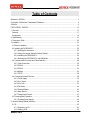
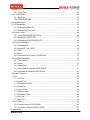

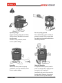

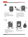
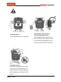

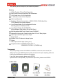
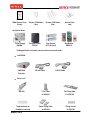
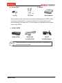


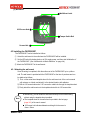

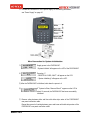
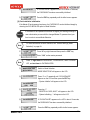

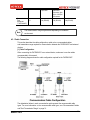
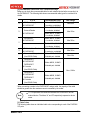
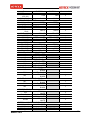
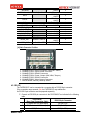
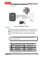

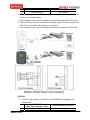
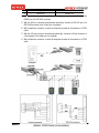
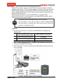
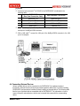
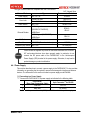
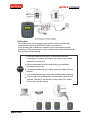

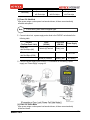
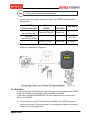
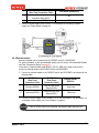
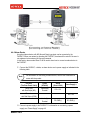
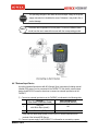
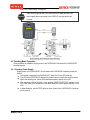
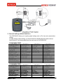
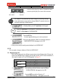

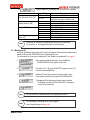
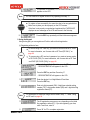

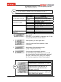
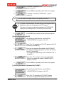
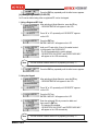
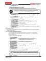
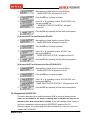
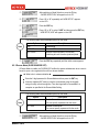


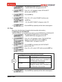


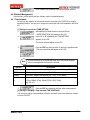
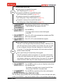

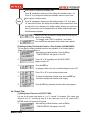
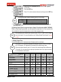
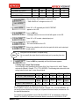


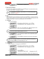
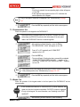
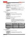
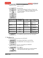
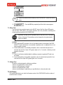

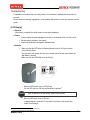
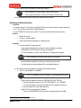


![ASK[EM] Format Proximity Card Reader](http://vs1.manualzilla.com/store/data/005664035_1-4bfcda642b959ea77ca1da56751cb6af-150x150.png)
![13.56MHz [MIFARE] Contactless Smart Card](http://vs1.manualzilla.com/store/data/005689074_1-1b5ba2b7f854420e24ee51932ec4423a-150x150.png)