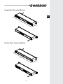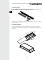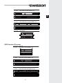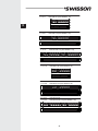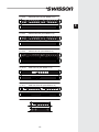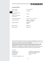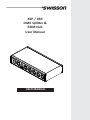
1
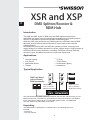
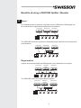
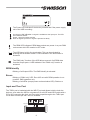
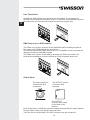
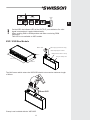
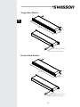
XSP / XSR DMX Splitter & RDM Hub User Manual USER MANUAL English E D Revisions History Revision 1 1 Description First Draft Proofread Date 24.04.2012 14.02.2014 Copyright © 2012 SWISSON AG 1 XSR and XSP E DMX Splitter/Booster & RDM Hub Introduction The XSR and XSP series of RDM hubs and DMX splitter/boosters from SWISSON can easily and economically be integrated into any lighting system where it is desirable to split and boost DMX and RDM signals. While the XSP splits and boost only DMX signals, the XSR also detects RDM data and uses its bidirectional functionality to report back to the controller (Lighting Board). All output ports on both XSP and XSR are optically isolated. A strong power supply allows for a reliable operation in a broad voltage range. A large program of XSR and XSP devices is available, consisting of different housings, different connector types and different numbers of input and output ports. Applications Concert Lighting Live Events Multimedia Shows Theater TV Sets Theme Parks Achitectural Lighting Installations Typical Application DMX Light Board with or without RDM functionality DMX Fixtures with or without RDM functionality DMX Dimmers with or without RDM functionality The XSR works within DMX / RDM environments, but can also operate mainly in pure DMX environments. The XSR is a good solution for those who expect to use RDM in future, because the XSR acts as a normal DMX splitter if there is no RDM data. The XSP works only within DMX evironments. Unpacking The DMX Splitter is packaged in a cardboard box. The following items are included: - The device - This user manual 2 Safety Information Consider the following notes mandatory when you set up, connect and use the XSP / XSR. This product is approved for professional use only, it is not intended for household usage. Follow the safety instructions closely, when setting up, connecting and using the device. Read the manual before operating the device and pay attention to all the instructions or warnings given in this manual or printed on the product. Use this device only in accordance with local laws and regulations. Safety Precautions Disconnect the device from the AC power supply before removing any cover or part, including fuse, even when not in use. Ensure the device is electrically connected to ground (earth). Use only a source of AC power supply that complies with local building and electrical regulations and which has both overload and ground-fault (earth fault) protection. Connect the device to a AC power supply using the supplied power cable. Before using the device, check that the power distribution equipment and cables are in perfect condition and rated for the current required of all connected devices. Isolate the device from power supply immediately if the power cable or power plug are in any way damaged, defective or wet, or if they show signs of overheating. Do not expose the device to rain or moisture. Do not operate the device if any cover or component is missing, damaged or deformed. Refer any service operation not described is this manual to SWISSON AG. Provide unrestricted airflow around the device. Do not operate the device where the ambient temperature exceed 55C (131F) Do not modify the device in any way other than described in this manual or install other than genuine SWISSON parts. Do not attempt to bypass the fuse. Replace defective fuse with one of the specified type and rating only. When suspending the device, ensure that the supporting structure and all hardware used is capable to withstand at least 10 times the weight of all devices suspended together. Install as described in this manual, a secondary attachment such as a safety cable that has been approved by an official body such as, e.g. TÜV (German Technical Monitoring Association) as a safety attachment for the total weight it secures. The safety cable must comply with EN 60598-2-17 Section 17.6.6 and be capable of bearing a static suspended load representing 10 times the actual weight of the device. Make sure that all external covers and rigging hardware are securely fastened. Provide clearance underneath the work area and a stable platform whenever installing, servicing or moving an overhead device. Do not use the device in areas where it is exposed to direct sunlight. Do not use the device in areas that are considered to be 'highly inflammable'. 3 E Benefits of using a XSP/XSR Splitter / Booster E Boost On installations with excessively long cable runs the DMX and/or RDM signal can be compromised or significantly weakened by the distance. good signal weak signal bad signal The XSP/XSR boosts the signals thus eliminating signal interference encountered in such situations. good signal weak signal good signal Regeneration In harsh environments DMX and RDM signals can be disturbed or corrupted. good signal disturbed signal disturbance bad signal disturbance The XSP/XSR cleans and regenerates the signals. good signal disturbed signal good signal disturbance 4 Splitting A simple split of signal lines is not allowed. The bidirectional operation of RDM is even more sensitive to the split than DMX. E not allowed A split of the signal lines is possible with the XSR / XSP by using different output ports. Reduction of Reflection Problems Signal reflection is a common problem in large DMX installations or on long signal lines. The bidirectional operation of RDM is more sensitive to reflections than DMX. Weak reflection with large delay. Signal OK Strong reflection with large delay. Bad signal ! Strong reflection with small delay. Signal OK The XSP/XSR splits the line into smaller segments with a regenerated signal, which reduces the delay of the reflection at each segment. Reflection with small delay. Signal OK Reflection with small delay. Signal OK 5 Protection In case of an over voltage on the DMX and RDM line(s), all devices on that line can be damaged. E The XSP/XSR separates the line into multiple segments. The over voltage is restricted to the concerned segment. The XSP/XSR itself is well protected against transient over voltage and the optical isolation of each port prevents a damage to other ports and segments in case of a permanent over voltage. XSP Block Diagram Control Logic Optical Isolation Optical Isolation Optical Isolation Optical Isolation Optical Isolation Line Termination Transmitter Transmitter Transmitter Transmitter Transmitter Protection Protection Protection Protection Protection Protection In Port Thru Port Termination Receiver Out Port 1 Out Port 2 Out Port 3 Out Port 4 Out Port 5 6 XSR Block Diagram Control Logic E Optical Optical Optical Optical Line Termination Transceiver Transceiver Transceiver Transceiver Transceiver Protection Protection Protection Protection Protection Protection In Port Thru Port DMX Only Optical Termination Transceiver Out Port 1 Out Port 2 Out Port 3 Out Port 4 Out Port 5 Mains Connection Two different mains connections are available: The US versions are delivered by SWISSON with an "Edison Plug" (NEMA-5-15). These models carry a "-US" suffix at the end. The international versions are supplied plugless. SWISSON distributors or dealers may deliver the devices with a country specific plug. Yellow/Green : Earth Brown : Phase US Versions (-US suffix) Live Neutral Ground (Earth) Blue : Neutral International Versions Wire (US System) Wire (EU System) black brown white blue green yellow/green Symbol L N or Consult a qualified electrician if you have any doubts about proper installation. The socket where the device is plugged in must be close to the device and easy to access. 7 Input Section of XSP Versions The Input section of versions with XLR connectors E The Input section of the versions with terminals: The “input” and “thru” terminals are located on the back of the device. The Power LED indicates if the device is powered and if the power supply unit of the XSP is working. A green LED indicates if a signal is available at the Input port. A red LED indicates if the received signal is faulty. The XSP has a built-in line termination. This can be activated by pressing the termination button. A LED indicates if the termination is activated. Input Section XSR Versions The Input section of the XSR versions with XLR connectors The Input section of the XSR versions with terminals: The “input” and “thru” terminals are located on the back of the device. 8 E The Power LED indicates if the device powered and if the power supply unit of the XSR is working. A multicolor LED indicates if a signal is available at the Input port. The LED has 2 different states: Green: Signal is present and Ok Red: No signal is present or signal is present but faulty The RDM LED indicates if RDM data packets are preset. In a pure DMX environment this LED remains in OFF state. The XSR has a built-in line termination. This can be activated by pressing the termination button. A LED indicates if the termination is activated. The "DMX only" function of the XSR allows removal of all RDM data from the Output ports. A LED indicates if the "DMX only" function is activated. RDM Identify Blinking of all Output LEDs: The RMD Identify is activated. Errors Blinking of “DMX only” LED: Error UID not valid. RDM operation is not possible. DMX operation only. Blinking of all LEDs (except power and termination LED): Fatal error Input and Thru Port The THRU port is hardwired with the INPUT port and allows to daisy-chain the devices, even when the XSR is not powered. On all XSP and XSR models with a 5-Pin XLR connector the pin 4 and 5 are also looped through to the THRU port. On all other models pin 4 & 5 are not available. Line Protection Termination Input Port Transceiver Thru Port 1 2 3 4 5 1 2 3 4 5 9 Line Termination E All XSP and XSR splitters have a built-in line termination. The termination is activated by pressing the termination button. On terminal and Installation versions the button can only be accessed using a tool (such as a paper clip). DMX Only (only on XSR models) The "DMX only" function removes all non DMX data before sending the data to the Output ports. RDM data will be removed too. This can be helpfull when DMX devices are not compatible and do not check the data they receive as valid DMX signals. The "DMX only" function is activated by pressing the "DMX only" button. On terminal and Installation versions, the button is only accessible with a tool. Output Ports The output section of versions with XLR connectors: The OUTPUT section of versions with terminals: The OUTPUT terminals are located on the back of the devices. Each Output port is individually optically isolated, meaning that it is totally isolated from the other Output ports and the Input selection. The Pins 4&5 on models with 5-Pin XLR connectors are not connected. 10 Controller Supply Control Logic Optical Isolation Output Port Port Supply Transceiver Bias Network Protection n.c. 1 2 3 4 5 E On the XSR, the indicator LED of the OUTPUT ports indicates if a valid signal is transmitted. It works bidirectionally: When sending DMX or RDM packets and when receiveing RDM responses. This LED is not available on XSP models. XSP / XSR Box Models Mains cable Mains plug (US-Versions only) cable length approx. 145cm M10 female threat for clamp 45mm Ring for safety wire 217.5mm 112mm The M10 screw which enters the XSP/XSR should not exceed a maximum length of 20mm. 20mm MAX Clamp is not included with the XSP/XSR. 11 Single Rack Models E 482mm 45mm 112mm cable length approx. 145cm Mains plug (US-Versions only) Double Rack Models 45mm 482mm 112mm cable length approx. 145cm Mains plug (US-Versions only) 12 Single Rack Terminal Models E 482mm 45mm 112mm Double Rack Terminal Models 482mm 45mm 112mm 13 Terminal Models The terminal models of the XSP/XSR series come with pluggable terminal blocks. The terminal blocks are located on the back of the devices. E XSP/XSR terminal models are shipped with the terminal blocks. They can accept 2 wires up to AWG 17 (~1mm ) Installation Models The XSP/XSR installation model is manufactured to be installed by certified professionals. This version has no plugs. The connections are all located inside the device. Input port Mains Thru port Output ports cover grommet 14 XSP Standard Program 10 11 63 11 11 63 XSP-3B XSP-3B-US (with NEMA 5-15) E Front view Rear view 10 11 74 11 11 74 XSP-3R XSP-3R-US (with NEMA 5-15) Front view Rear view 10 11 85 11 11 85 XSP-3R-3R XSP-3R-3R-US (with NEMA 5-15) Front view Rear view 10 11 62 11 11 62 XSP-5B XSP-5B-US (with NEMA 5-15) Front view Rear view 10 11 72 11 11 72 XSP-5R XSP-5R-US (with NEMA 5-15) Front view Rear view 10 11 82 11 11 82 XSP-5R-5R XSP-5R-5R-US (with NEMA 5-15) Front view Rear view 15 10 11 60 11 11 60 XSP-5B5 XSP-5B5-US (with NEMA 5-15) Front view E Rear view 10 11 70 11 11 70 XSP-5R5 XSP-5R5-US (with NEMA 5-15) Front view Rear view 10 11 80 11 11 80 XSP-5R5-5R5 XSP-5R5-5R5-US (with NEMA 5-15) Front view Rear view 10 11 87 11 11 87 XSP-5R2-5R2 XSP-5R2-5R2-US (with NEMA 5-15) Front view Rear view 10 11 84 11 11 84 XSP-5R-5R5 XSP-5R-5R5-US (with NEMA 5-15) Front view Rear view 10 11 86 11 11 86 XSP-5R-3R XSP-5R-3R-US (with NEMA 5-15) Front view Rear view 16 10 11 50 11 11 50 XSP-TR5 XSP-TR5-US (with NEMA 5-15) Front view OUT 5 OUT 4 OUT 3 OUT 2 OUT 1 THRU E IN Rear view 10 11 51 11 11 51 XSP-TR5-TR5 XSP-TR5-TR5-US (with NEMA 5-15) Front view OUT 5 OUT 4 OUT 3 OUT 2 OUT 1 THRU IN OUT 5 OUT 4 OUT 3 OUT 2 OUT 1 THRU IN Rear view 10 11 98 XSP-IB5-W Front view Rear view XSR Standard Program 10 12 10 11 12 10 XSR-3B XSR-3B-US (with NEMA 5-15) Front view Rear view 10 12 20 11 12 20 XSR-3R XSR-3R-US (with NEMA 5-15) Front view Rear view 10 12 30 11 12 30 XSR-3R-3R XSR-3R-3R-US (with NEMA 5-15) Front view Rear view 17 10 12 11 11 12 11 XSR-5B XSR-5B-US (with NEMA 5-15) Front view E Rear view 10 12 21 11 12 21 XSR-5R XSR-5R-US (with NEMA 5-15) Front view Rear view 10 12 31 11 12 31 XSR-5R-5R XSR-5R-5R-US (with NEMA 5-15) Front view Rear view 10 12 16 11 12 16 XSR-5B5 XSR-5B5-US (with NEMA 5-15) Front view Rear view 10 12 26 11 12 26 XSR-5R5 XSR-5R5-US (with NEMA 5-15) Front view Rear view 10 12 33 11 12 33 XSR-5R5-5R5 XSR-5R5-5R5-US (with NEMA 5-15) Front view Rear view 18 10 12 35 11 12 35 XSR-5R2-5R2 XSR-5R2-5R2-US (with NEMA 5-15) Front view E Rear view 10 12 34 11 12 34 XSR-5R-5R5 XSR-5R-5R5-US (with NEMA 5-15) Front view Rear view 10 12 32 11 12 32 XSR-5R-3R XSR-5R-3R-US (with NEMA 5-15) Front view Rear view 10 12 50 11 12 50 XSR-TR5 XSR-TR5-US (with NEMA 5-15) Front view OUT 5 OUT 4 OUT 3 OUT 2 OUT 1 THRU IN Rear view 10 12 51 11 12 51 XSR-TR5-TR5 XSR-TR5-TR5-US (with NEMA 5-15) Front view OUT 5 OUT 4 OUT 3 OUT 2 OUT 1 THRU IN OUT 5 OUT 4 Rear view 10 12 51 XSR-IB5-W Front view Rear view 19 OUT 3 OUT 2 OUT 1 THRU IN Technical Data E Mains Voltage 100 - 240 [VAC] Main Frequency 50/60 [Hz] Current Consumption Single Units 0.2 [A] Current Consumption Double Units 0.4 [A] Operating Temperature 0°F to 131°F (-17C to 55C) Protocol Standard ANSI E1.11 (DMX-512) ANSI E1.20 (RDM) Safety Standards EN60950-1 UL508 EMC emission EN55103-1 EMC immunity EN55103-2 No part of this documentation may be reproduced or transmitted in any form or by any means, electronically or mechanically, including photocopying and recording, without the prior written permission of SWISSON AG. The information in this documentation is supplied without warranty of any kind, either directly or indirectly, and is subject to change without prior written notice. SWISSON AG, its employees or appointed representatives will not be held responsible for any damages to software, hardware, or data, arising as a direct or indirect result of operating and/or handling the product(s) mentioned herein. Issued by SWISSON AG Fabrikstrasse 21 CH-3250 Lyss Switzerland SWISSON of AMERICA Corp. 2419 East Harbor Blvd. #34 Ventura, CA 93001 U.S.A. e-mail: [email protected] 20