1
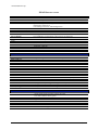
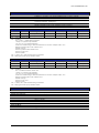
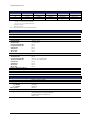
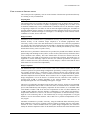
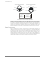
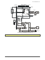
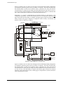
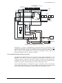
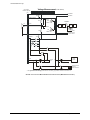
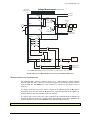
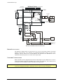
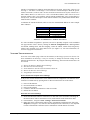
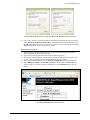
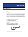
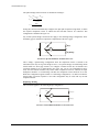
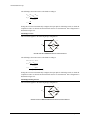
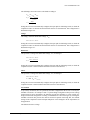
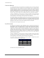
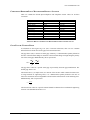
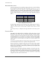
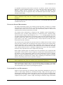
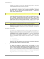
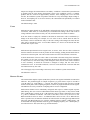
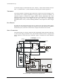
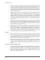
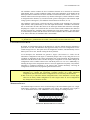
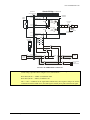
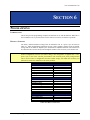
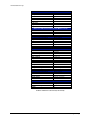
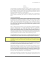
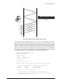
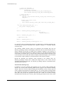
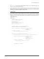
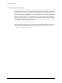
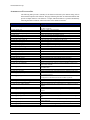
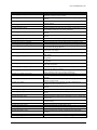
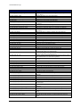
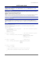
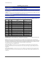
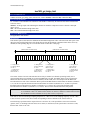
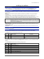
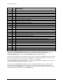
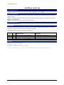
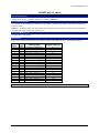
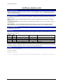
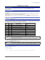
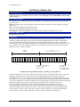
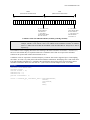
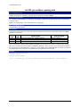
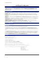
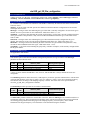
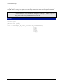
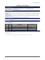
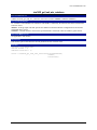
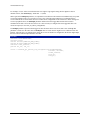
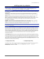
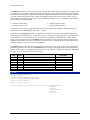
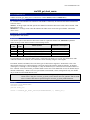
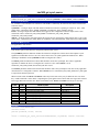
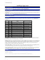
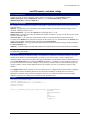
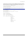
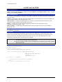
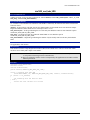
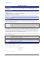
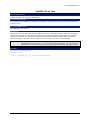
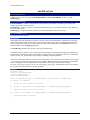
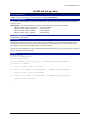
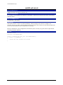
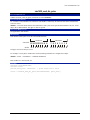
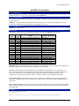
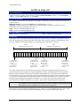
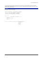
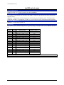
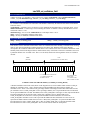
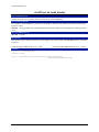
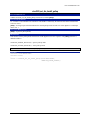
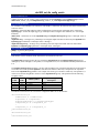
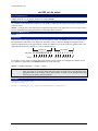
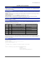
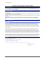
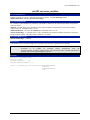
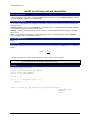
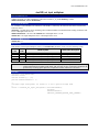
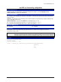
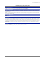
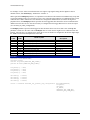
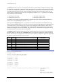
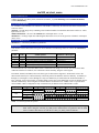
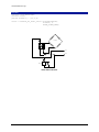
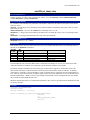
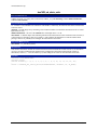
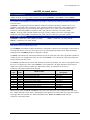
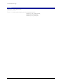
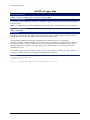
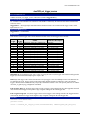
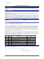
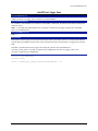
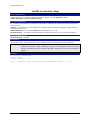
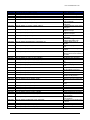
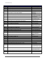
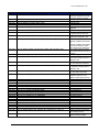
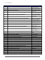
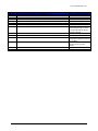
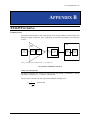
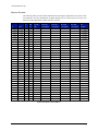
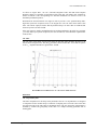
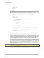
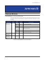
www.vtiinstruments.com As shown in Figure B-8-1, the CIC (Cascaded Integrator-Comb) and FIR (Finite Impulse Response) filters are responsible for decimation of the ADC data. The sample rates available are shown in Table B-1. The corresponding CIC and FIR decimations are shown as well as the maximum passband frequencies. Decimation has been divided into two stages in order to provide a “low” passband droop and a high alias rejection at frequencies close to the Nyquist rate. The CIC filter cannot achieve this alone. The scheme employed ensures that the passband droop is no more than ±0.01 dB and that the alias rejection is at least 100 dB. If the user requires a smaller passband than the one passband indicated in the table for a particular fs or if they must reject specific frequencies, the user can make use of the IIR filters explained later in this section. CIC Filter The CIC filter in the FPGA receives input from the anti-alias filter decimates the data by the factors shown in Figure B-8-2. The max_fc parameter, shown in Table B-1, is less than or equal to 0.05 f so . Stopband attenuation is greater than -110 dB. FIGURE B-8-2: ALIAS REJECTION AS A FUNCTION OF DECIMATION DSP Filters CIC compensation filter This filter compensates for the droop in the passband of the CIC. Six tap FIR filters are designed to compensate for the variable droop as a function of sampling rates. The need to have more than one filter arises due to the wide range of decimation factors. The CIC droop after compensation is bounded by ±0.0002. The group delay of this filter is 2.5 samples. Filtering operations done in floating point. EX1629 Filtering 319