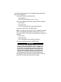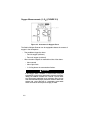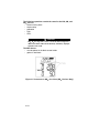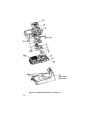
1
Solaris®
MultiGas Detector
Operating Manual
In North America, to contact your nearest stocking location, dial toll-free 1-800-MSA-2222
To contact MSA International, dial 1-412-967-3354 or 1-800-MSA-7777
© MINE SAFETY APPLIANCES COMPANY 2005 - All Rights Reserved
This manual is available on the internet at www.msanet.com
Manufactured by
MSA INSTRUMENT DIVISION
P.O. Box 427, Pittsburgh, Pennsylvania 15230
(L) Rev 2
10046201
" WARNING
THIS MANUAL MUST BE CAREFULLY READ BY ALL INDIVIDUALS WHO HAVE OR WILL
HAVE THE RESPONSIBILITY FOR USING OR SERVICING THE PRODUCT. Like any piece
of complex equipment, this instrument will perform as designed only if it is used and serviced in accordance with the manufacturer’s instructions. OTHERWISE, IT COULD FAIL TO
PERFORM AS DESIGNED AND PERSONS WHO RELY ON THIS PRODUCT FOR THEIR
SAFETY COULD SUSTAIN SEVERE PERSONAL INJURY OR DEATH.
The warranties made by Mine Safety Appliances Company with respect to the product are
voided if the product is not used and serviced in accordance with the instructions in this
manual. Please protect yourself and others by following them. We encourage our customers to write or call regarding this equipment prior to use or for any additional information relative to use or service.
i
Table of Contents
Chapter 1,
Instrument Safety and Certifications . . . . . .1-1
" WARNING . . . . . . . . . . . . . . . . . . . . . . . . . . . . .1-1
Safety Limitations and Precautions . . . . . . . . . . . . . . . .1-2
Date of Instrument Manufacture . . . . . . . . . . . . . . . . . . .1-4
Certifications . . . . . . . . . . . . . . . . . . . . . . . . . . . . . . . . . .1-4
Electronic Interference . . . . . . . . . . . . . . . . . . . . . . . . . .1-4
Chapter 2,
Using the Solaris Multigas Detector . . . . . . .2-1
Turning ON the Solaris Multigas Detector . . . . . . . . . . .2-1
Last Cal Date . . . . . . . . . . . . . . . . . . . . . . . . . . . . . . . . .2-1
Cal Due Date . . . . . . . . . . . . . . . . . . . . . . . . . . . . . . . . .2-2
Instrument Alarm Bypass Options . . . . . . . . . . . . . . . . .2-2
Fresh Air Set Up Option . . . . . . . . . . . . . . . . . . . . . . . . .2-3
" WARNING . . . . . . . . . . . . . . . . . . . . . . . . . . . . .2-3
Figure 2-1. Battery Indicator . . . . . . . . . . . . . . . . . .2-3
Battery Life Indicator (FIGURE 2-1) . . . . . . . . . . . . . .2-4
Battery Warning . . . . . . . . . . . . . . . . . . . . . . . . . . . . .2-4
Battery Shutdown . . . . . . . . . . . . . . . . . . . . . . . . . . . .2-4
" WARNING . . . . . . . . . . . . . . . . . . . . . . . . . . . . .2-4
Sensor Missing Alarm . . . . . . . . . . . . . . . . . . . . . . . . .2-5
" CAUTION . . . . . . . . . . . . . . . . . . . . . . . . . . . . . .2-5
" WARNING . . . . . . . . . . . . . . . . . . . . . . . . . . . . .2-5
" WARNING . . . . . . . . . . . . . . . . . . . . . . . . . . . . .2-5
Calibration Check . . . . . . . . . . . . . . . . . . . . . . . . . . . . . .2-6
Measuring Gas Concentrations . . . . . . . . . . . . . . . . . . .2-6
Combustible gases (% LEL) (FIGURE 2-2) . . . . . . . . .2-6
Figure 2-2. Instrument in LEL Alarm . . . . . . . . . . . .2-6
" WARNING . . . . . . . . . . . . . . . . . . . . . . . . . . . . .2-7
Oxygen Measurements (% O2) (FIGURE 2-3) . . . . . .2-8
Figure 2-3. Instrument in Oxygen Alarm . . . . . . . . .2-8
" WARNING . . . . . . . . . . . . . . . . . . . . . . . . . . . . .2-8
Toxic Gas Measurements (FIGURE 2-4) . . . . . . . . . . .2-9
ii
Solaris Multigas Detector Equipped with an
NO2 Sensor Only . . . . . . . . . . . . . . . . . . . . . . . . . . . . .2-9
Figure 2-4. Instrument in Toxic Gas Alarm . . . . . . .2-9
" WARNING . . . . . . . . . . . . . . . . . . . . . . . . . . . . .2-9
" CAUTION . . . . . . . . . . . . . . . . . . . . . . . . . . . . .2-10
Figure 2-5. Instrument in NO2 Gas Alarm
(NO2 Versions Only) . . . . . . . . . . . . . . . . . .2-10
Safe LED . . . . . . . . . . . . . . . . . . . . . . . . . . . . . . . . . .2-11
Operating Beep . . . . . . . . . . . . . . . . . . . . . . . . . . . . .2-11
Viewing Optional Displays (FIGURE 2-6) . . . . . . . . . .2-12
Figure 2-6. Flow Diagram . . . . . . . . . . . . . . . . . . .2-12
Peak Readings (PEAK) (FIGURE 2-7) . . . . . . . . . . .2-13
Minimum Readings (MIN) (FIGURE 2-8) . . . . . . . . . .2-13
Figure 2-7. PEAK Readings on the Display . . . . .2-13
Figure 2-8. MIN Reading on the Display . . . . . . . .2-13
Short Term Exposure Limits (STEL) (FIGURE 2-9) . .2-14
To Reset the STEL: . . . . . . . . . . . . . . . . . . . . . . . . . .2-14
Figure 2-9. Exposure Page with STEL Alarm . . . .2-14
Time Weighted Average (TWA) (FIGURE 2-10) . . . .2-15
" WARNING . . . . . . . . . . . . . . . . . . . . . . . . . . . .2-15
Figure 2-10. Exposure Page with TWA Alarm . . . .2-15
To Reset the TWA: . . . . . . . . . . . . . . . . . . . . . . . . . . .2-16
" WARNING . . . . . . . . . . . . . . . . . . . . . . . . . . . .2-16
Time Display (FIGURE 2-11) . . . . . . . . . . . . . . . . . . .2-17
Date Display (FIGURE 2-12) . . . . . . . . . . . . . . . . . . .2-17
Turning OFF the Solaris Multigas Detector . . . . . . . . .2-17
Figure 2-11 Time Display . . . . . . . . . . . . . . . . . . . .2-17
Figure 2-12. Date Display . . . . . . . . . . . . . . . . . . .2-17
" CAUTION . . . . . . . . . . . . . . . . . . . . . . . . . . . . . .3-1
Chapter 3,
Setting up the Solaris Multigas Detector . . .3-1
Power Systems . . . . . . . . . . . . . . . . . . . . . . . . . . . . . . .3-1
Table 3-1. Battery Capacity Reductions
Expected at Colder Temperatures . . . . . . . . .3-1
Battery Charging (Lithium Ion Battery version only) . .3-1
To Charge the Instrument . . . . . . . . . . . . . . . . . . . . . .3-1
Battery Replacement (Alkaline Battery Version Only) .3-2
Changing Instrument Settings . . . . . . . . . . . . . . . . . . . .3-2
iii
" WARNING . . . . . . . . . . . . . . . . . . . . . . . . . . . . .3-2
Figure 3-1. Battery Replacement . . . . . . . . . . . . . . .3-2
Accessing the Instrument Setup Mode . . . . . . . . . . . . .3-3
Chapter 4,
Calibration . . . . . . . . . . . . . . . . . . . . . . . . . . . .4-1
" WARNING . . . . . . . . . . . . . . . . . . . . . . . . . . . . .4-1
Calibrating the Solaris Multigas Detector . . . . . . . . . . . .4-1
Table 4-1. Autocalibration and Required
Calibration Cylinders . . . . . . . . . . . . . . . . . . .4-1
To Calibrate the Solaris Multigas Detector
(FIGURE 4-1): . . . . . . . . . . . . . . . . . . . . . . . . . . . . . . .4-2
Figure 4-1. Calibration Flow Chart . . . . . . . . . . . . . .4-3
Figure 4-2. Zero Flag . . . . . . . . . . . . . . . . . . . . . . . .4-4
Figure 4-3. CAL Flag . . . . . . . . . . . . . . . . . . . . . . . .4-4
Autocalibration Failure . . . . . . . . . . . . . . . . . . . . . . . . .4-5
Chapter 5,
Warranty and Live Maintenance Procedures 5-1
MSA Portable Instrument Warranty . . . . . . . . . . . . . . . .5-1
Cleaning and Periodic Checks . . . . . . . . . . . . . . . . . . . .5-2
" WARNING . . . . . . . . . . . . . . . . . . . . . . . . . . . . . .5-2
" WARNING . . . . . . . . . . . . . . . . . . . . . . . . . . . . . .5-2
Storage . . . . . . . . . . . . . . . . . . . . . . . . . . . . . . . . . . . . . .5-3
Shipment . . . . . . . . . . . . . . . . . . . . . . . . . . . . . . . . . . . .5-3
Troubleshooting . . . . . . . . . . . . . . . . . . . . . . . . . . . . . . .5-3
" WARNING . . . . . . . . . . . . . . . . . . . . . . . . . . . . . .5-3
Live Maintenance Procedures . . . . . . . . . . . . . . . . . . . .5-4
Sensor Replacement . . . . . . . . . . . . . . . . . . . . . . . . . .5-4
" WARNING . . . . . . . . . . . . . . . . . . . . . . . . . . . . . .5-4
" WARNING . . . . . . . . . . . . . . . . . . . . . . . . . . . . . .5-5
Chapter 6,
Performance Specifications . . . . . . . . . . . . . .6-1
Table 6-1. Certifications (see instrument label to
determine applicable approval) . . . . . . . . . . .6-1
Table 6-2. Instrument Specifications . . . . . . . . . . .6-1
iv
Table 6-3. COMBUSTIBLE GAS - Typical
Performance Specifications . . . . . . . . . . . . . .6-2
Table 6-4. COMBUSTIBLE GAS - Cross
Reference Factors for Solaris
General-Purpose Calibration Using
Calibration Cylinder (P/N 10045035)
Set to 58% LEL Pentane Simulant . . . . . . . . .6-2
Table 6-5. Combustible Gas - Cross Reference
Factors for Solaris FX . . . . . . . . . . . . . . . . . .6-4
Table 6-6. OXYGEN - Typical Performance
Specifications . . . . . . . . . . . . . . . . . . . . . . . . .6-5
6-7. CARBON MONOXIDE (appropriate
models only) - Typical Performance
Specifications . . . . . . . . . . . . . . . . . . . . . . . . .6-6
Table 6-8. CARBON MONOXIDE - Cross
Reference Factors for Solaris Calibration
Using Calibration Cylinder (P/N 10045035) . .6-6
Table 6-9. HYDROGEN SULFIDE (appropriate
models only) - Typical Performance
Specifications . . . . . . . . . . . . . . . . . . . . . . . . .6-7
Table 6-10. HYDROGEN SULFIDE - Cross
Reference Factors for Solaris Calibration
Using Calibration Cylinder (P/N10045035) . .6-7
Table 6-11. Nitrogen (Appropriate Models Only)
Dioxide Typical Performance Specifications .6-8
Table 6-12. Nitrogen Dioxide (Appropriate
Models Only) Cross Reference Factors for
Solaris Calibration . . . . . . . . . . . . . . . . . . . . .6-8
Chapter 7,
Replacement and Accessory Parts . . . . . . . .7-1
Table 7-1. Replacement Parts List . . . . . . . . . . . . .7-2
Table 7-2. Accessory Parts List . . . . . . . . . . . . . . .7-3
Table 7-3. Accessory Parts List
(NO2 Versions Only) . . . . . . . . . . . . . . . . . . .7-3
Figure 7-1. Replacement Parts (see Table 7-1) . . . .7-4
v
Chapter 1,
Instrument Safety and Certifications
The Solaris Multigas Detector is for use by trained and qualified
personnel. It is designed to be used when performing a hazard
assessment to:
•
Assess potential worker exposure to combustible and toxic gases
and vapors
•
Determine the appropriate gas and vapor monitoring needed for a
workplace.
The Solaris Multigas Detector can be equipped to detect:
•
•
•
Combustible gases and certain combustible vapors
Oxygen-deficient or oxygen-rich atmospheres
Specific toxic gases for which a sensor is installed.
" WARNING
•
Read and follow all instructions carefully.
•
Check calibration before each day's use and adjust
if necessary.
•
Check calibration more frequently if exposed to
silicone, silicates, lead-containing compounds,
hydrogen sulfide, or high contaminant levels.
•
Recheck calibration if unit is subjected to physical
shock.
•
Use only to detect gases/vapors for which a sensor
is installed.
•
Do not use to detect combustible dusts or mists.
•
Make sure adequate oxygen is present.
•
Do not block sensors.
•
Have a trained and qualified person interpret
instrument readings.
•
Do not recharge Li ION battery in a combustible
atmosphere.
•
Do not replace alkaline batteries in a combustible
atmosphere.
• Do not alter or modify instrument.
INCORRECT USE CAN CAUSE SERIOUS PERSONAL
INJURY OR DEATH.
1-1
Safety Limitations and Precautions
Carefully review the following safety limitations and precautions before
placing this instrument in service:
•
•
The Solaris Multigas Detector is designed to:
•
Detect gases and vapors in air only
•
Detect only specified toxic gases for which a sensor is
installed.
Perform the following check before each day's use to verify proper
instrument operation:
•
•
Calibration check (see Calibration Check section). Adjust
calibration if the readings are not within the specified limits.
Check calibration more frequently if the unit is subjected to
physical shock or high levels of contaminants. Also, check
calibration more frequently if the tested atmosphere contains the
following materials, which may desensitize the combustible gas
sensor and reduce its readings:
•
Organic silicones
•
Silicates
•
Lead-containing compounds
•
Hydrogen sulfide exposures over 200 ppm or exposures
over 50 ppm for one minute.
•
The minimum concentration of a combustible gas in air that can
ignite is defined as the Lower Explosive Limit (LEL). A combustible
gas reading of "100" or “5.00” indicates the atmosphere is above
100% LEL or 5.00% CH4, respectively, and an explosion hazard
exists. In such cases, the instrument LockAlarm feature activates.
Move away from contaminated area immediately.
•
Do not use the Solaris Multigas Detector to test for combustible or
toxic gases in the following atmospheres as this may result in
erroneous readings:
1-2
•
Oxygen-deficient or oxygen-rich atmospheres
•
Reducing atmospheres
•
Furnace stacks
•
Inert environments
•
Atmospheres containing combustible airborne mists/dusts.
•
Do not use the Solaris Multigas Detector to test for combustible
gases in atmospheres containing vapors from liquids with a high
flash point (above 38°C, 100°F) as this may result in erroneously
low readings.
•
Do not block sensor openings as this may cause inaccurate
readings. Do not press on the face of the sensors, as this may
damage them and cause erroneous readings. Do not use
compressed air to clean the sensor holes, as the pressure may
damage the sensors.
•
Allow sufficient time for unit to display accurate reading. Response
times vary based on the type of sensor being utilized (see Chapter
6, "Performance Specifications").
•
All instrument readings and information must be interpreted by
someone trained and qualified in interpreting instrument readings
in relation to the specific environment, industrial practice and
exposure limitations.
•
Do not recharge lithium ion battery or replace alkaline batteries in a
hazardous area. Use only battery chargers made available by MSA
for use with this instrument; other chargers may damage the
battery pack and the unit. Dispose of batteries in accordance with
local health and safety regulations.
•
Do not alter this instrument; otherwise, damage may result.
•
Use of the GalaxyTM Automated Test System is an alternate MSHAapproved method for calibrating MSHA-approved Solaris
instruments.
•
Use only calibration gas that is 2.5% Methane with an accuracy of
+5% when calibrating MSHA-approved Solaris instruments.
•
The maximum acceptable user-settable (password protected)
Galaxy Automated Test System tolerance on Bump Limits must
only be set to 10% or less when calibrating MSHA-approved
Solaris instruments.
•
For 30 CFR Part 75 determinations, the maximum acceptable usersettable (password protected) Galaxy Automated Test System
tolerance on Bump Limits must only be set to such that 19.5%
oxygen can be detected with an accuracy of +0.5% when
calibrating MSHA-approved Solaris instruments.
1-3
Date of Instrument Manufacture
The date of manufacture of your Solaris Multigas Detector is coded into
the instrument serial number.
•
The last three digits represent the month (the letter) and the year
(the two-digit number).
•
The letter corresponds to the month starting with A for January, B
for February, etc.
Certifications
Tests completed by MSA verify that the Solaris Multigas Detector meets
applicable industry and government standards as of the date of
manufacture. Refer to Chapter 6, TABLE 6-1, for specific certifications.
Electronic Interference
•
This instrument generates, uses, and can radiate radio frequency
energy. Operation of this instrument may cause interference, in
which case, the user may be required to correct.
•
This device is test equipment and is not subject to FCC technical
regulations. However, it has been tested and found to comply with
the limits for a Class A digital device specified in Part 15 of the
FCC regulations.
•
This digital apparatus does not exceed the Class A limits for radio
noise emissions from digital apparatus set out in the Radio
Interference Regulations of the CRTC.
•
There is no guarantee that interference will not occur. If this
instrument is determined to cause interference to radio or
television reception, try the following corrective measures:
1-4
•
Reorient or relocate the receiving antenna
•
Increase separation between the instrument and the
radio/TV receiver
•
Consult an experienced radio/TV technician for help.
Chapter 2,
Using the Solaris Multigas Detector
Turning ON the Solaris Multigas Detector
Press the Power ON button; the instrument displays:
1. A self-test:
• All segments display
• Audible alarm sounds
• Alarm light illuminate
• Vibrator activates
• Software version displays
• Internal diagnostics
• "VISUAL OFF" displays if red LEDs disabled
• "BACKLITE OFF" displays if backlight disabled
• "AUDIBLE OFF" displays if buzzer disabled
• "VIBRATE OFF" displays if vibrator disabled.
2. Alarm setpoints:
• Low
• High
• STEL (if activated)
• TWA (if activated)
3. Calibration gas (expected calibration gas values)
4. Time and date (if data logging option installed)
5. Last CAL date (if data logging option installed)
6. CAL due date (if activated and if data logging option installed)
7. Instrument warm-up period
8. Fresh Air Setup option.
Last Cal Date
The Solaris Multigas Detector is equipped with a “last successful
calibration date” feature. The date shown is the last date that all
installed sensors were successfully calibrated. "LAST CAL" is displayed
with this date in the following format:
•
MM:DD:YY
If any of the sensors were not previously calibrated,
"LAST CAL, INVALID" is displayed.
2-1
Cal Due Date
The Solaris Multigas Detector (with data logging and software version
1.1 or higher) is equipped with a Calibration Due Date feature. To
activate this feature, see Chapter 3, “Accessing the Instrument Setup
Mode”.
If the calibration due date feature is activated, following Last Cal Date,
the message "CAL DUE, X DAYS" appears on the instrument LCD.
•
x = the number of days until a calibration is due,
user selectable for 1 to 180 days.
If the number of days until calibration is due reaches 0, an alert occurs
and "CAL DUE, --NOW--" displays.
•
Press the RESET button to clear the alert and continue with the
instrument warm-up period.
During Normal Measure mode, if the calibration due date feature is
activated and calibration is due, the instrument beeps and displays
"CAL DUE" every 30 seconds until the unit is calibrated.
Perform a calibration check before each day’s use to verify proper
instrument operation (see Chapter 2, “Calibration Check”).
Instrument Alarm Bypass Options
The Solaris Multigas Detector (with software version 1.1 or higher) is
equipped with a feature to disable or silence the visual, backlight,
audible, and vibrator options. To activate this feature, see Chapter 3,
“Accessing the Instrument Setup Mode”.
If any of these options (visual, backlight, audible, or vibrator) are
disabled during instrument startup, the Solaris Detector displays:
•
"VISUAL OFF" if the red LEDs are disabled
•
"BACKLITE OFF" if backlight is disabled
•
"AUDIBLE OFF" if audible buzzer is disabled
•
"VIBRATE OFF" if the vibrator is disabled.
If the visual, audible, or vibrator options are disabled, "ALARM OFF"
flashes on the LCD during Normal Measure mode.
2-2
Fresh Air Set Up Option
(for automatic zero adjustment of the Solaris Multigas Detector sensors)
NOTE: The Fresh Air Setup (FAS) has limits. If a hazardous level of
gas is present, the Solaris Multigas Detector ignores the FAS
command and goes into alarm.
" WARNING
Do not activate the Fresh Air Setup unless you are certain
you are in fresh, uncontaminated air; otherwise, inaccurate
readings can occur which can falsely indicate that a hazardous atmosphere is safe. If you have any doubts as to the
quality of the surrounding air, do not use the Fresh Air Setup
feature. Do not use the Fresh Air Setup as a substitute for
daily calibration checks. The calibration check is required to
verify span accuracy. Failure to follow this warning can
result in serious personal injury or death.
Persons responsible for the use of the Solaris Multigas Detector must
determine whether or not the Fresh Air Setup option should be used.
The user's abilities, training and normal work practices must be
considered when making this decision.
1. Turn ON the Solaris Multigas Detector.
•
Once the instrument self check is complete, ZERO? flashes for
10 seconds.
2. To perform a Fresh Air Setup, push the ON/OFF button while
ZERO? is flashing.
3. To immediately skip the FAS, push the RESET button.
•
If no buttons are pushed, the ZERO? automatically stops
flashing after the 10 seconds have expired and the FAS is not
performed.
Figure 2-1. Battery Indicator
2-3
Battery Life Indicator (FIGURE 2-1)
•
The battery condition icon continuously displays in the upper
portion of the screen, regardless of the selected page.
•
As the battery charge dissipates, segments of the battery icon go
blank until only the outline of the battery icon remains.
Battery Warning
•
A Battery Warning indicates that a nominal 15 minutes of operation
remain before instrument batteries are completely depleted.
NOTE: Duration of remaining instrument operation during Battery
Warning depends on ambient temperatures.
•
When the Solaris Multigas Detector goes into Battery Warning:
• Battery Life indicator flashes
• “BATT WRN” flashes every 15 seconds
• Alarm sounds
• Lights flash every 15 seconds
•
The Solaris Multigas Detector continues to operate until the
instrument is turned OFF or battery shutdown occurs.
Battery Shutdown
When the batteries can no longer operate the instrument, the instrument
goes into Battery Shutdown mode:
•
LOW and BATTERY flash on the display
•
Alarm sounds and lights flash
•
Alarm can be silenced by pressing the RESET button
•
No other pages can be viewed
•
After approximately one minute, the instrument automatically
turns OFF.
" WARNING
When Battery Shutdown condition sounds, stop using the
instrument; it can no longer alert you of potential hazards
since it does not have enough power to operate properly:
1. Leave the area immediately.
2. Turn OFF the instrument if it is ON.
3. Report to the person responsible for maintenance
4. Recharge the battery or replace the batteries.
2-4
Failure to follow this procedure, could result in serious personal injury or death.
" CAUTION
During "Battery Low" condition, prepare to exit the work
area since the instrument could go into "Battery Shutdown"
at any time, resulting in loss of sensor function. Depending
on the age of the batteries, ambient temperature and other
conditions, the instrument "Battery Low" and "Battery
Shutdown" times could be shorter than anticipated.
" WARNING
Recharge the instrument or replace the batteries when the
"Battery Low" or "Battery Shutdown" conditions occur.
Sensor Missing Alarm
The Solaris Multigas Detector will enter the Sensor Missing alarm if the
instrument detects that an enabled sensor is not properly installed in the
instrument. For O2, CO, and H2S sensors, the Sensor Missing feature
is checked when the instrument is turned ON and when leaving the
Setup mode. The combustible Sensor Missing feature is continually
monitored. If a sensor is detected as missing, the following occurs:
•
SENSOR and MISSING flash on the display
•
The flag above the sensor detected as missing flashes on the
display
•
Alarm sounds and lights flash
•
Alarm can be silenced by pressing the RESET button
•
No other pages can be viewed
•
After approximately one minute, the instrument automatically turns
OFF.
" WARNING
If a Sensor Missing condition occurs, stop using the instrument; it can no longer alert you of potential hazards.
1. Leave the area immediately.
2. Turn OFF the instrument if it is ON.
3. Report to the person responsible for maintenance
Failure to follow this procedure could result in serious personal injury or death.
2-5
Calibration Check
The calibration check is simple and should only take about one minute.
Perform this calibration check before each day's use.
1. Turn ON the Solaris Multigas Detector in clean, fresh air.
2. Verify that readings indicate no gas is present.
3. Attach calibration cap to the Solaris Multigas Detector.
4. Ensure that "TOP" and "↑" on the calibration cap are oriented so
that “TOP” is positioned at the top of the instrument.
5. Attach regulator (supplied with calibration kit) to the cylinder.
6. Connect tubing (supplied with calibration kit) to the regulator.
7. Attach other end of tubing to the calibration cap.
8. Open the valve on the regulator.
•
The regulator flow rate is 0.25 lpm.
•
The reading on the Solaris Multigas Detector display should be
within the limits stated on the calibration cylinder or limits
determined by your company.
•
If necessary, change cylinder to introduce other calibration
gases.
•
If readings are not within these limits, the Solaris Multigas
Detector requires recalibration. See Chapter 4, "Calibration."
Measuring Gas Concentrations
Combustible Gases (% LEL) (FIGURE 2-2)
Figure 2-2. Instrument in LEL Alarm
2-6
The Solaris Multigas Detector can be equipped to detect combustible
gases in the atmosphere.
•
Alarms sound when concentrations reach:
•
Alarm Setpoint or
•
•
100% LEL (Lower Explosive Limit), 5% CH4.
When the combustible gas indication reaches the Alarm Setpoint:
•
Alarm sounds
•
Alarm lights flash
•
•
% LEL or CH4 flag above the concentration flashes.
To silence the alarm, press the RESET button.
NOTE: The alarm will stay silent if the alarm condition has cleared.
•
When the combustible gas indication reaches 100% LEL or 5%
CH4, the LockAlarm circuit locks the combustible gas reading and
alarm and:
TM
•
•
Alarm sounds
•
Alarm lights flash
•
100 or 5.00 appears on the display and flashes.
This alarm cannot be reset with the RESET button.
" WARNING
If the 100% LEL or 5.00% CH4 alarm condition is reached, you
may be in a life-threatening situation; there is enough gas in
the atmosphere for an explosion to occur. In addition, any
rapid up-scale reading followed by a declining or erratic reading can also be an indication that there is enough gas for an
explosion. If either of these indications occur, leave and move
away from the contaminated area immediately. Failure to follow this warning can result in serious personal injury or death.
•
After moving to a safe, fresh-air environment, reset the alarm by
turning OFF the instrument and turning it ON again.
2-7
Oxygen Measurements (% O2) (FIGURE 2-3)
Figure 2-3. Instrument in Oxygen Alarm
The Solaris Multigas Detector can be equipped to detect the amount of
oxygen in the atmosphere.
•
•
Two conditions trigger the alarm:
•
Too little oxygen (deficient)
•
Too much oxygen (enriched).
When the alarm setpoint is reached for either of the above:
•
Alarm sounds
•
Alarm lights flash
•
% O2 flag above the concentration flashes.
" WARNING
If the Oxygen alarm condition is reached while using the
instrument as a personal or area monitor, leave the area immediately; the ambient condition has reached a preset alarm
level. If using the instrument as an inspection device, do not
enter the area without proper protection. Failure to follow this
warning will cause exposure to a hazardous environment
which can result in serious personal injury or death.
2-8
Toxic Gas Measurements (FIGURE 2-4)
Figure 2-4. Instrument in Toxic Gas Alarm
•
The Solaris Multigas Detector can be equipped to detect:
• Carbon Monoxide (CO) and/or
• Hydrogen Sulfide (H2S) in the atmosphere.
•
When the alarm setpoint is reached for Carbon Monoxide (CO)
and/or Hydrogen Sulfide (H2S):
• Alarm Sounds
• Alarm Lights flash
• PPM CO or PPM H2S flag above the concentration flashes.
" WARNING
If the Toxic Gas alarm condition is reached while using the
instrument as a personal or area monitor, leave the area
immediately; the ambient condition has reached a preset
alarm level. If using the instrument as an inspection device,
do not enter the area without proper protection. Failure to
follow this warning will cause over-exposure to toxic gases,
which can result in serious personal injury or death.
Solaris Multigas Detector
Equipped with an NO2 Sensor Only
• The Solaris Multigas Detector can be equipped to detect NO2.
Units are identified:
•
at turn-ON by displaying 'TOX2 NO2'
•
during continuous operation, by scrolling 'Solaris NO2' across the
display.
2-9
The following operations remain the same for the H2S, CO, and
NO2 sensors:
• sensor missing alarm
• sensor setup
• calibration
• TWA
• STEL.
" CAUTION
NO2, H2S or any toxic sensor cannot be interchanged to a
different location within the instrument; otherwise, improper
operation will result.
The NO2 Sensor:
• must be placed in the black sensor holder
•
gasket is also black.
Figure 2-5. Instrument in NO2 Gas Alarm (NO2 Versions Only)
2-10
Safe LED
The Solaris Multigas Detector is equipped with a green "SAFE LED".
This green SAFE LED will flash every 15 seconds under the following
conditions:
•
The green SAFE LED is enabled
•
Instrument is on the normal Measure Gases page
•
•
Combustible reading is 0% LEL or 0%CH4
Oxygen (O2) reading is 20.8%
•
Carbon Monoxide (CO) reading is 0 ppm
•
•
Hydrogen Sulfide (H2S) reading is 0 ppm
No gas alarms are present (low or high)
•
Instrument is not in Low Battery warning or alarm
•
CO, H2S, STEL and TWA readings are 0 ppm.
Operating Beep
The Solaris Multigas Detector is equipped with an operating beep. This
operating beep activates every 30 seconds by momentarily beeping the
horn and flashing the alarm LEDs under the following conditions:
•
Operating beep is enabled
•
Instrument is on normal Measure Gases page
•
Instrument is not in Battery warning
•
Instrument is not in Gas alarm
•
Audible and visual options enabled.
2-11
Viewing Optional Displays (FIGURE 2-6)
The diagram shown in FIGURE 2-6 describes the flow for optional
displays.
Figure 2-6. Flow Diagram
Press the PAGE button to move to:
2-12
Peak Readings (PEAK) (FIGURE 2-7)
Figure 2-7. PEAK Readings on the Display
•
•
PEAK appears in the upper portion of the display to show the
highest levels of gas recorded by the Solaris Multigas Detector
since:
•
Turn-ON or
•
Peak readings were reset.
To Reset the Peak Readings:
1. Access the Peak page.
2. Press the RESET button.
Minimum Readings (MIN) (FIGURE 2-8)
Figure 2-8. MIN Reading on the Display
•
This page shows the lowest level of oxygen recorded by the
Solaris Multigas Detector since:
2-13
•
Turn-ON or
•
MIN reading was reset.
•
MIN appears in the upper portion of the display.
•
To reset the MIN Reading:
1. Access the Min page.
2. Press the RESET button.
Short Term Exposure Limits (STEL) (FIGURE 2-9)
Figure 2-9. Exposure Page with STEL Alarm
•
The STEL flag appear in the upper portion of the display to show
the average exposure over a 15-minute period.
•
When the amount of gas detected by the Solaris Multigas Detector
is greater than the STEL limit:
•
Alarm sounds
•
Alarm lights flash
•
STEL flashes.
To Reset the STEL:
1. Access the STEL page.
2. Press the RESET button.
The STEL alarm is calculated over a 15-minute exposure. Calculation
examples are as follows:
•
Assume the Detector has been running for at least 15 minutes:
2-14
•
15-minute exposure of 35 PPM:
(15 minutes x 35 PPM)
= 35 PPM
15 minutes
•
10-minute exposure of 35 PPM
5-minute exposure of 15 PPM:
(10 minutes x 35 PPM) + (5 minutes x 5 PPM)
= 25 PPM
15 minutes
" WARNING
If the STEL alarm condition is reached while using the
instrument as a personal or area monitor, leave the contaminated area immediately; the ambient gas concentration has
reached the preset STEL alarm level. Failure to follow this
warning will cause over-exposure to toxic gases, which can
result in serious personal injury or death.
Time Weighted Average (TWA) (FIGURE 2-10)
Figure 2-10. Exposure Page with TWA Alarm
•
The TWA flag will appear in the upper portion of the display to
show the average exposure since the instrument was turned ON or
the TWA reading was reset.
•
When the amount of gas detected by the Solaris Multigas Detector
is greater than the eight-hour TWA limit:
•
Alarm Sounds
2-15
•
Alarm Lights Flash
•
TWA flashes.
To Reset the TWA:
1. Access the TWA page.
2. Press the RESET button.
The TWA alarm is calculated over an eight-hour exposure. Calculation
examples are as follows:
•
1-hour exposure of 50 PPM:
(1 hour x 50 PPM) + (7 hours x 0 PPM)
= 6.25 PPM
8 hours
•
4-hour exposure of 50 PPM
4-hour exposure of 100 PPM:
(4 hours x 50 PPM) + (4 hours x100 PPM)
= 75 PPM
8 hours
•
12-hour exposure of 100 PPM:
(12 hours x 100 PPM)
= 150 PPM
8 hours
NOTE: The accumulated reading is always divided by eight hours.
" WARNING
If the TWA alarm condition is reached while using the instrument as a personal or area monitor, leave the contaminated
area immediately; the ambient gas concentration has
reached the preset TWA alarm level. Failure to follow this
warning will cause over-exposure to toxic gases, which can
result in serious personal injury or death.
Time Display (FIGURE 2-11)
2-16
Figure 2-11 Time Display
•
TIME appears on the display to show the current time of day in a
24-hour format.
Date Display (FIGURE 2-12)
Figure 2-12. Date Display
•
DATE appears on the display with the current date displayed in the
following format:
•
MM:DD:YY
Turning OFF the Solaris Multigas Detector
Push and Hold the ON-OFF button for three seconds.
NOTE: Releasing the ON-OFF button before the three seconds elapse
returns the instrument to the Measure page.
2-17
Chapter 3,
Setting up the Solaris Multigas Detector
Power Systems
The Solaris instrument is supplied with a Li ION battery or three AA
Alkaline batteries. These batteries have a nominal runtime of 14 and 12
hours, respectively. In colder temperatures, battery output may be
reduced. See TABLE 3-1 for capacity reductions expected for batteries
at these temperatures.
Table 3-1.
Battery Capacity Reductions Expected at Colder Temperatures
TEMPERATURE
Li ION
AA ALKALINE
21°C (70°F)
None
None
-20°C (-4°F)
40%
90%
Battery Charging (Lithium Ion Battery version only)
Charge the battery by using the Charger supplied with the instrument.
" CAUTION
Use of any charger, other than the Charger supplied with the
instrument, may damage or improperly charge the batteries.
•
The charger is capable of charging a completely depleted pack in
less than four hours in normal, room-temperature environments.
NOTE: Allow very hot or cold instruments to stabilize for one hour
at room temperature before attempting to charge.
•
Minimum and maximum ambient temperature to charge the
instrument is 10°C, 50°F and 35°C, 95°F, respectively.
•
For best results, charge the instrument at room temperature (23°C)
To Charge the Instrument
•
Carefully place instrument into the charge stand.
•
Charger status is indicated by the LED.
•
Green: Charging complete
•
Red: Charging in process
•
Yellow: Failure Mode; remove from charger.
3-1
•
"CHARGE" flashes on the Solaris display when the unit is installed
on the charge stand
•
This is not an indication that the charge is complete
Battery Replacement (Alkaline Battery Version Only)
" WARNING
Do not remove the intrument’s batteries in a hazardous area
To replace Solaris Multigas Detector batteries:
1. Unscrew the captive screws from the bottom and top of the battery
door.
2. Replace the batteries, using only batteries listed on the Approval
Label.
3. Attach battery door to instrument and tighten the screws.
Figure 3-1. Battery Replacement
Changing Instrument Settings
•
•
Many options can be set using the instrument buttons.
If the Solaris Multigas Detector was ordered with the optional
datalogging, the MSA FiveStar LINK software can be used to set
most of the instrument selections, including some that cannot be
changed from the instrument's front panel buttons.
3-2
Accessing the Instrument Setup Mode
1. Press and hold the RESET button while turning the instrument ON.
•
SETUP displays.
NOTE: In all of the following selections in this Set-up mode:
•
Press ON/OFF to enter chosen value/go to the next page.
•
Press the ON/OFF button to store the chosen value.
•
Press RESET to decrement by one or toggle ON/OFF.
•
Press and hold RESET to decrement by 10.
•
Press PAGE to increment by one or toggle ON/OFF.
•
Press and hold PAGE to increment by 10.
2. Enter password default "672".
3. Press ON/OFF to enter password.
•
Correct Password: instrument continues/beeps three times.
•
Incorrect Password: instrument enters the Measure mode.
4. Password ON/OFF (turns the password protection ON or OFF)
5. New Password Setup (changes the password)
6. Instrument Options Setup
•
Safe LED ON/OFF
•
Instrument Alarm Bypass Options Setup
•
•
Visual alarm ON/OFF (red LEDs)
•
Audible alarm ON/OFF (buzzer)
•
Vibrator ON/OFF
Backlight ON/OFF
•
Backlight timer (10 seconds to 10 minutes)
•
OP beep ON/OFF
•
STEL/TWA ON/OFF
•
Time (if data logging option installed)
•
Date (if data logging option installed)
•
CAL Due ON/OFF (if data logging option installed)
•
CAL Due duration (1 to 180 days)
3-3
7. LEL/CH4 Setup
• Sensor ON/OFF (turns the sensor ON or OFF)
•
Display Combustible Gas Type?
•
Methane
•
Pentane
•
Hydrogen
•
Propane
•
LEL or Ch4 mode (displays % LEL (for any gas)
or % CH4 (for Methane only)
•
Low Alarm (sets the low combustible alarm)
•
High Alarm (sets the high combustible alarm)
•
Cal Gas (sets the expected combustible calibration gas)
8. O2 Setup
• Sensor ON/OFF (turns the sensor ON or OFF)
•
Low Alarm
•
High Alarm
9. CO Setup
•
Sensor ON/OFF (turns the sensor ON or OFF)
•
Low Alarm (sets the low CO alarm)
•
High Alarm (sets the high CO alarm)
•
STEL Alarm (if enabled) (sets the STEL CO alarm)
•
TWA Alarm (if enabled) (sets the TWA CO alarm)
•
Cal Gas (sets the expected CO calibration gas)
10.TOX2 Setup (H2S or NO2)
• Sensor ON/OFF (sets TOX2 sensor ON or OFF)
•
Low Alarm (sets the low TOX2 alarm)
•
High Alarm (sets the high TOX2 alarm)
•
STEL Alarm (if enabled) (sets the STEL TOX2 alarm)
•
TWA Alarm (if enabled) (sets the TWA TOX2 alarm)
•
Cal Gas (sets the expected TOX2 calibration gas)
3-4
Chapter 4,
Calibration
Calibrating the Solaris Multigas Detector
Each Solaris Multigas Detector is equipped with an Autocalibration
feature to make unit calibration as easy as possible.
The Autocalibration sequence resets instrument zeroes and adjusts
sensor calibration for known concentrations of calibration gases.
Table 4-1. Autocalibration and Required Calibration Cylinders
SENSORS
EXPECTED GAS*
CONCENTRATION
FOUR-GAS
CYLINDER
(P/N 10045035)
FOUR-GAS
CYLINDER
(P/N 10058171)
FOUR-GAS
CYLINDER
(P/N 10058034)
Combustible
58% LEL
Combustible
2.5% CH4
Oxygen
15%
Carbon Monoxide
60 ppm
Hydrogen Sulfide
20 ppm
Nitrogen Dioxide
10 ppm
*Factory Default
LEL Mode
Methane Mode
LEL Mode
NOTES:
• Refer to Chapter 3, "Setting up the Multigas Detector", for instructions on changing the
autocalibration expected gas concentrations if calibration gas with concentrations other
than those listed above will be used to calibrate the instrument.
• For 30 C.F.R. Part 75 determinations (MSHA versions), the Solaris Multigas Detector
must be operated in the 0-5% by volume CH4 mode and must be calibrated with 2.5%
by volume methane.
" WARNING
The expected gas concentrations must match the gas concentrations listed on the calibration cylinder(s). Failure to
follow this warning will cause an incorrect calibration, which
can result in serious personal injury or death.
4-1
To Calibrate the Solaris Multigas Detector (FIGURE 4-1):
1. Turn ON the instrument and verify that battery is sufficiently
charged.
2. Wait until the Measure Gases page appears.
3. Push and hold the RESET button until CAL ZERO? flashes on the
display (FIGURE 4-2).
4. Push the ON-OFF button to zero the instrument.
•
Instrument must be in fresh air to perform the zero.
•
CAL ZERO flashes.
NOTE: To skip the Zero procedure and move directly to the
calibration span procedure, push the RESET button.
If no button is pushed for 30 seconds, the instrument
returns to the Measure mode.
•
4-2
Once the zeros are set, CAL SPAN? flashes (FIGURE 4-3).
Figure 4-1. Calibration Flow Chart
4-3
Figure 4-2. Zero Flag
Figure 4-3. CAL Flag
4. Connect the appropriate calibration gas to the instrument.
5. Attach the calibration cap to the instrument.
a. Connect one end of the tubing to the calibration cap.
b. Connect other end of tubing to the cylinder regulator (supplied
in the calibration kit).
c. Ensure that "TOP" and "↑" on the calibration cap are oriented
so that "TOP" is positioned at the top of the instrument.
6. Open the valve on the regulator.
7. Push the ON-OFF button to calibrate (span) the instrument.
•
CAL SPAN flashes for approximately 90 seconds.
•
If autocalibration sequence passes, the instrument beeps three
times and returns to the Measure mode.
NOTE:
4-4
To skip calibration and return to the Measure mode,
push the RESET button.If no button is pushed for 30 seconds,
the instrument returns to the Measure mode.
8. Remove the calibration cap.
9. Close the valve on the regulator.
NOTE: The autocalibration procedure adjusts the span value for any
sensor that passes the test; sensors that fail autocalibration are
left unchanged.
Since residual gas may be present, the instrument may briefly
go into an exposure alarm after the calibration sequence is
completed.
Autocalibration Failure
If the Solaris Multigas Detector cannot calibrate one or more sensor(s),
the instrument goes into the Autocalibration Failure Page and remains
in alarm until the RESET button is pushed. Sensors that could not be
calibrated are indicated by dashed lines on the concentration display.
4-5
Chapter 5,
Warranty and Live Maintenance
Procedures
MSA Portable Instrument Warranty
1.
WarrantyITEM
WARRANTY PERIOD
Chassis and electronics
Two years
All sensors, unless otherwise specified
Two years
This warranty does not cover filters, fuses, etc. Certain other
accessories not specifically listed here may have different warranty
periods. This warranty is valid only if the product is maintained and
used in accordance with Seller's instructions and/or
recommendations. The Seller shall be released from all obligations
under this warranty in the event repairs or modifications are made
by persons other than its own or authorized service personnel or if
the warranty claim results from physical abuse or misuse of the
product. No agent, employee or representative of the Seller has
any authority to bind the Seller to any affirmation, representation or
warranty concerning this product. Seller makes no warranty
concerning components or accessories not manufactured by the
Seller, but will pass on to the Purchaser all warranties of
manufacturers of such components. THIS WARRANTY IS IN LIEU
OF ALL OTHER WARRANTIES, EXPRESSED, IMPLIED OR
STATUTORY, AND IS STRICTLY LIMITED TO THE TERMS
HEREOF. SELLER SPECIFICALLY DISCLAIMS ANY
WARRANTY OF MERCHANTABILITY OR OF FITNESS FOR A
PARTICULAR PURPOSE.
2. Exclusive Remedy- It is expressly agreed that Purchaser's sole
and exclusive remedy for breach of the above warranty, for any
tortious conduct of Seller, or for any other cause of action, shall be
the replacement at Seller's option, of any equipment or parts
thereof, which after examination by Seller is proven to be defective.
Replacement equipment and/or parts will be provided at no cost to
Purchaser, F.O.B. Seller's Plant. Failure of Seller to successfully
replace any nonconforming equipment or parts shall not cause the
remedy established hereby to fail of its essential purpose.
5-1
3. Exclusion of Consequential Damages- Purchaser specifically
understands and agrees that under no circumstances will seller be
liable to purchaser for economic, special, incidental or
consequential damages or losses of any kind whatsoever, including
but not limited to, loss of anticipated profits and any other loss
caused by reason of nonoperation of the goods. This exclusion is
applicable to claims for breach of warranty, tortious conduct or any
other cause of action against seller.
Cleaning and Periodic Checks
As with all electronic equipment, the Solaris Multigas Detector will
operate only if it is properly maintained.
" WARNING
Alteration of the Solaris Multigas Detector, beyond the procedures described in this manual or by anyone other than a
person authorized by MSA, could cause the instrument to
fail to perform properly. Use only genuine MSA replacement
parts when performing any maintenance procedures
described in this manual. Substitution of components can
seriously impair instrument performance, alter intrinsic
safety characteristics or void agency approvals.
FAILURE TO FOLLOW THIS WARNING CAN RESULT
IN SERIOUS PERSONAL INJURY OR DEATH.
" WARNING
Do not attempt to clean the sensor cover while it is in place;
sensor damage may occur. The tops of sensors are very
fragile; do not touch or apply pressure to the tops of any
sensors. If a sensor is damaged, it can cause the unit to give
false readings.
5-2
Storage
When not in use, store your Solaris Multigas Detector in a safe, dry
place between -5° and 40°C (23° and 104°F).
" WARNING
After storage, always recheck instrument calibration before
use. During storage, sensors may drift or become inoperative and may not provide warnings of dangers to the health
and lives of users.
Shipment
Pack the Solaris Multigas Detector in its original shipping container with
suitable padding. If the original container is unavailable, an equivalent
container may be substituted. Seal instrument in a plastic bag to protect
it from moisture. Use sufficient padding to protect it from the rigors of
handling. Damage due to improper packaging or damage in shipment is
not covered by the instrument's warranty.
Troubleshooting
The Solaris Multigas Detector will operate reliably for years when cared
for and maintained properly. If the instrument becomes inoperative, you
may contact MSA at:
.
•
MSA Instrument Division
Service Department
1000 Cranberry Woods Drive
Cranberry Township, PA 16066-5207
1-800-MSA-INST
To contact MSA International, please call:
•
1-412-967-3000 or 1-800-MSA-7777
5-3
Live Maintenance Procedures
Sensor Replacement
1. Verify that the instrument is turned OFF.
2. Remove the front case.
3. Gently lift out and properly discard the sensor to be replaced.
•
•
Remove the CO or H2S sensor with a nonconductive or
nonmetallic flat blade screwdriver or similar tool by pressing
against the sensor holder tab and lifting out the sensor:
•
CO sensor holder tab is in upper left corner
•
H2S sensor holder tab is in upper right corner.
Remove the combustible or oxygen sensor gently with your
fingers only.
" WARNING
Remove and reinstall sensors carefully, ensuring that the
components are not damaged. Damage can adversely affect
the intrinsic safety of the instrument and result in serious
personal injury or death.
4. Verify that combustible and oxygen sensor standoffs are installed.
NOTE: Sensor positions cannot be changed:
•
The CO sensor must be placed in the red sensor holder.
•
•
Note that the CO gasket in the sensor is also red.
The H2S sensor must be placed in the blue sensor holder.
• Note that the H2S gasket in the sensor is also blue.
5. Carefully align the new sensor contact pins with the sockets on the
printed circuit board.
6. Press the new sensor into place.
5-4
•
Press the CO sensor into place by placing the sensor
under the sensor holder tab first; then, press into place
(CO sensor tab is located in the upper left-hand corner of
the sensor Holder).
•
Press the H2S sensor into place by placing the sensor
under the sensor holder tab first; then, press into place
(H2S sensor tab is located in the upper right-hand corner
of the sensor Holder).
•
If a CO or an H2S sensor is not to be installed, ensure that
a “dummy” cell is installed properly in place.
7. Replace the sensor gasket and sensor filters in the front case.
8. Re-install the screws.
" WARNING
Verification of calibration response is required; otherwise,
the instrument will not perform as required, and persons
relying on this product for their safety could sustain serious
personal injury or death.
5-5
Chapter 6,
Performance Specifications
Table 6-1. Certifications
(see instrument label to determine applicable approval)
HAZARDOUS
LOCATIONS
PERFORMANCE
APPLICABLE
EUROPEAN
DIRECTIVES
US
(NON-MINING)
UL913 for Class I, Div. 1, Groups A, B, C
and D, Tamb=-20°C to +50°C
US (MINING)
30 CFR Part 22, Methane Detector
CANADA
CSA C22.2, No. 157 for Class I, Div. 1, Groups
A, B, C and D, Tamb=-20°C to +50°C
EUROPE
EEx ia dIIC, Tamb=-20°C to +50°C
AUSTRALIA
Ex ia S Zone 0 I/IIC
US (MINING)
30 CFR Part 22, Methane Detector
CANADA
CSA C22.2, No. 152 for Methane
EUROPE
IEC60529
EUROPE
EN50054, EN50057 (for Methane)
EUROPE
EN50271 (Software and Digital Technologies)
ATEX
94/9/EC
II 2G
EEx ia d IIC, T3 (157°C), Tamb=-20°C to +50°C
EMC 89/336/EEC EN50270 (EN50081-1, EN50082-2)
Table 6-2. Instrument Specifications
TEMPERATURE
RANGE
NORMAL
0 to 40°C
EXTENDED*
-20 TO 0°C, 40 to 50°C
SHORT PERIODS
-40 TO-20°C (15 minutes)
INGRESS
PROTECTION
RATING (IP)
MEASUREMENT
METHOD
IP65
COMBUSTIBLE GAS
Catalytic Sensor
OXYGEN
Electrochemical Sensor
TOXIC GASES
Electrochemical Sensors
6-1
FACTORY-SET
ALARM SETPOINTS
CO
H2S
LEL
O2
NO2
*NOTE:
LOW ALARM
35 PPM
10 PPM
10%
19.5%
2.5 PPM
HIGH ALARM
100 PPM
15 PPM
20%
23.0%
5.0 PPM
STEL
400
15
--5.0
TWA
35
10
--2.5
Extended temperature range indicates gas readings may vary slightly
if calibrated at room temperature. For optimal performance, calibrate instrument
at temperature of use.
Table 6-3.
COMBUSTIBLE GAS - Typical Performance Specifications
RANGE
0 to 10 0% LEL or 0 to 5.00% CH4
RESOLUTION
1% LEL or 0.05% CH4
REPRODUCIBILITY 3% LEL, 0% to 50% LEL reading or
.15% CH4, 0.00% to 2.50% CH4 (normal temperature range*)
5% LEL, 50% to 100% LEL reading or
.25% CH4, 2.50% to 5.00% CH4 (normal temperature range*)
5% LEL, 0% to 50% LEL reading or
.25% CH4, 0.00% to 2.50% CH4 (extended temperature range*)
RESPONSE TIME
8% LEL, 50% to 100% LEL reading or .
0.40% CH4, 2.50% to 5.00% CH4 (extended temperature range*)
90% of final reading in 30 seconds (normal temperature range*)
(LEL only)
90% of final reading in 20 seconds (Methane)
*See TABLE 6-2 NOTE
Table 6-4.
COMBUSTIBLE GAS - Cross Reference Factors
for Solaris General-Purpose Calibration Using Calibration Cylinder
(P/N 10045035) Set to 58% LEL Pentane Simulant
COMBUSTIBLE GAS
6-2
MULTIPLY %LEL READING BY
Acetone
1.1
Acetylene
0.7
Acrylonitrile1
0.8
Benzene
1.1
Butane
1.0
1,3 Butadiene
0.9
COMBUSTIBLE GAS
MULTIPLY % LEL READING BY
n-Butanol
1.8
Carbon Disulfide1
2.2
Cyclohexane
1.1
2,2 Dimethylbutane
1.2
2,3 Dimethylpentane
1.2
Ethane
0.7
Ethyl Acetate
1.2
Ethyl Alcohol
0.8
Ethylene
0.7
Formaldehyde2
0.5
Gasoline
1.3
Heptane
1.4
Hydrogen
0.6
n-Hexane
1.3
Isobutane
0.9
Isobutyl Acetate
1.5
Isopropyl Alcohol
1.1
Methane
0.6
Methanol
0.6
Methyl Isobutyl ketone
1.1
Methylcyclohexane
1.1
Methyl Ethyl Ketone
1.1
Methyl Tertiary Butyl Ether
1.0
Mineral Spirits
1.1
iso-Octane
1.1
n-Pentane
1.0
Propane
0.8
Propylene
Styrene2
0.8
Tetrahydrofuran
0.9
Toluene
1.2
Vinyl Acetate
0.9
VM&P Naptha
1.6
O-Xylene
1.2
1.9
6-3
RESPONSE NOTES:
1. The compounds may reduce the sensitivity of the combustible gas sensor by poisoning
or inhibiting the catalytic action.
2. These compounds may reduce the sensitivity of the combustible gas sensor by
polymerizing on the catalytic surface.
3. For an instrument calibrated on Pentane,multiply the displayed %LEL value by the
conversion factor above to get the true %LEL.
4. These conversion factors should be used only if the combustible gas is known.
5. These conversion factors are typical for a Solaris Multigas Detector. Individual units
may vary by + 25% from these values
Table 6-5. COMBUSTIBLE GAS - Cross Reference Factors for
Solaris FX
This TABLE shows the variation in response of the 4P-50 CiTipel® on exposure to a
range of gases and vapors at the same % LEL concentration
GAS VAPOR
RELATIVE
SENSITIVITY*
GAS VAPOR
RELATIVE
SENSITIVITY*
Methane
100
Carbon monoxide
Propane
65
Acetone
115
70
nButane
65
Methyl ethyl ketone
55
n-Pentane
60
Toluene
40
n-Hexane
50
Ethyl acetate
60
n-Heptane
45
Hydrogen
115
n-Octane
40
Ammonia**
130
Methanol
95
Cyclohexane
55
Ethanol
85
Leaded petrol
60
Iso-propyl alcohol
60
Unleaded petrol
60
Acetylene
80
Ethylene
85
*Each sensitivity has been rounded to the nearest 5%.
**T90 for Ammonia is extended. Contact City Technology for details.
RESPONSE NOTES:
1. The compounds may reduce the sensitivity of the combustible gas sensor by poisoning
or inhibiting the catalytic action.
2. These compounds may reduce the sensitivity of the combustible gas sensor by
polymerizing on the catalytic surface.
3. The figures are experimentally derived and expressed relative to the methane signal
(= 100).
4. These conversion factors should be used only if the combustible gas is known.
5. The results are intended for guidance only. For the most accurate measurements, an
instrument should be calibrated using the gas under investigation.
6-4
Table 6-6. OXYGEN - Typical Performance Specifications
RANGE
RESOLUTION
0 to 25% O2
0.1% O2
REPRODUCIBILITY 0.7% O2, for 0 to 25% O2
0.7% O2 for O2 < = 15% (MSHA version only)
0.5% O2, for O2: <O2 < =25% (MSHA version only)
RESPONSE TIME
90% of final reading
30 seconds (normal temperature range*)
3 minutes (extended temperature range)
*See TABLE 6-2 NOTE
Environment and Oxygen Sensor Readings
A number of environmental factors may affect the oxygen sensor
readings, including changes in pressure, humidity and temperature.
Pressure and humidity changes affect the amount of oxygen actually
present in the atmosphere.
Pressure Changes
If pressure changes rapidly (e.g., stepping through airlock) the oxygen
sensor reading may temporarily shift, and possibly cause the detector to
go into alarm. While the percentage of oxygen may remain at or near
20.8%, the total amount of oxygen present in the atmosphere available
for respiration may become a hazard if the overall pressure is reduced
to a significant degree.
Humidity Changes
If humidity changes to any significant degree (e.g., going from a dry, air
conditioned environment to outdoor, moisture laden air), oxygen levels
can change up to 0.5%. This is due to water vapor in the air displacing
oxygen, thus reducing oxygen readings as humidity increases. The
oxygen sensor has a special filter to reduce the affects of humidity
changes on oxygen readings. This effect will not be noticed
immediately, but slowly impacts oxygen readings over several hours.
Temperature Changes
The oxygen sensor has built-in temperature compensation. However, if
temperature shifts dramatically, the oxygen sensor reading may shift.
Zero the instrument at a temperature within 30°C of the temperature-ofuse for the least effect.
6-5
Table 6-7.
CARBON MONOXIDE (appropriate models only) Typical Performance Specifications
RANGE
500 ppm CO
RESOLUTION
1 ppm CO, for 5 to 500 ppm CO
REPRODUCIBILITY
+5 ppm CO or 10% of reading, whichever is greater
0 to 300 ppm CO, +15% >300 ppm CO
(normal temperature range*)
+10 ppm CO or 20% of reading, whichever is greater
(extended temperature range*)
RESPONSE TIME
90% of final reading in 60 seconds (normal temperature range*)
*See TABLE 6-2 NOTE
Table 6-8. CARBON MONOXIDE - Cross Reference Factors
for Solaris Calibration Using Calibration Cylinder (P/N 10045035)
NOTE:
Data is presented as the indicated output in ppm, which would result from the
application of 100 ppm of the test gas.
TEST GAS (100 PPM)
100 +9
Hydrogen Sulfide (H2S)
4 +4
TEST GAS (100 PPM)
EQUIVALENT PPM
Sulfur Dioxide (SO2)
Nitrogen Dioxide (NO2)
0 +1
Nitric Oxide (NO)
70 +10
Chlorine (Cl2)
1 +8
Ammonia (NH3)
Hydrogen Chloride (HCl)
2 +4
Ethylene (C2H4)
Hydrogen Cyanide (HCN)
6-6
EQUIVALENT PPM
Carbon Monoxide (CO)
2 +6
3 +2
90 +9
0 +1
Methane (CH4)
Ethanol (EtOH)
0 +0
Hydrogen (H2)
70 +26
4 +5
Table 6-9. HYDROGEN SULFIDE (appropriate models only)
- Typical Performance Specifications
RANGE
RESOLUTION
REPRODUCIBILITY
200 ppm H2S
1 ppm H2S, for 3 to 200 ppm H2S
+2 ppm H2S or 10% of reading, whichever is greater
0 to 100 ppm H2S, +15% > 100 ppm H2S
(normal temperature range*)
+5 ppm H2S or 20% of reading, whichever is greater
(extended temperature range*)
RESPONSE TIME
90% of final reading in 60 seconds* (normal temperature range)
*See TABLE 6-2 NOTE
Table 6-10. HYDROGEN SULFIDE - Cross Reference Factors
for Solaris Calibration Using Calibration Cylinder (P/N10045035)
NOTE:
Data is presented as the indicated output in ppm, which would result from the
application of 100 ppm of the test gas
TEST GAS (100 PPM)
Hydrogen Sulfide (H2S)
Ethylene (C2H4)
Methane (CH4)
Hydrogen (H2)
TEST GAS (100 PPM)
EQUIVALENT PPM
100 +10
0 +0
0 +0
0 +0
EQUIVALENT PPM
Ammonia (NH3)
0 +0
Chlorine (Cl2)
Nitrogen Dioxide (NO2)
0 +0
Nitric Oxide (NO)
1 +1
-20 +2
Carbon Monoxide (CO)
4 +4
Hydrogen Chloride (HCl)
0 +0
Hydrogen Cyanide (HCN)
1 +1
Sulfur Dioxide (SO2)
Ethanol (EtOH)
10 +3
Toluene
0 +0
0 +0
6-7
Table 6-11. Nitrogen (Appropriate Models Only) Dioxide Typical
Performance Specifications
RANGE
50.0 ppm
RESOLUTION
0.1 ppm H2S, for 0.5 to 50.0 ppm NO2
+0.5 ppm NO2 or 10% of reading, whichever
is greater (normal temperature range*)
REPRODUCIBILITY
+0.5 ppm NO2 or 20% of reading, whichever
is greater (extended temperature range*)
RESPONSE TIME
90% of final reading in 60 seconds
(normal temperature range*)
*See TABLE 6-2 NOTE.
Table 6-12. Nitrogen Dioxide (Appropriate Models Only) Cross
Reference Factors for Solaris Calibration
NOTE: Data is presented as the indicated output in ppm, which would result from the
application of 10 ppm of the test gas
TEST GAS (10 PPM)
EQUIVALENT PPM
Hydrogen Sulfide (H2S)
Sulfur Dioxide (SO2)
-12.7 +1.2
Carbon Monoxide (CO)
0 +0
Nitric Oxide (NO)
0 +0
Ammonia (NH3)
Methane (CH4)
0 +0
6-8
-.6 +.1
0 +0
Chapter 7,
Replacement and Accessory Parts
7-1
Table 7-1. Replacement Parts List
ITEM
NO.
PART
PART NO.
1
Gasket, Sensor
Gasket, Sensor (FX only)
10044926
10055500
2
CO Button Cell Sensor
10046944
3
4
H2S Button Cell Sensor
O2 Sensor
10046945
10046946
5
Combustible Sensor
Combustible Sensor (FX only)
10046947
10055612
6
Case, Assembly, Front
Case, Assembly, Front (Alkaline only)
Case, Assembly, Front (FX only)
10044996
10068951
10055515
7
Sensor, Plug, Inactive, Button Cell (quantity: up to 2)
10046292
8
Insert, Support, Combustible Sensor
10046762
9
10
Insert, Support, O2 Sensor
Filter, Charcoal, CO
10047967
11
Charger, Cradle, Assembly (Rechargeable only)
10048185
12
Felt, Protection (quantity: 4)
10044927
13
Cap, Calibration Assembly
10044994
14
Fitting, Male Tapper Luer (quantity: 2)
637266
15
North American Power Supply (Rechargeable only)
10047342
16
17
Global Power Supply
Rear Case Assembly
Rear Case Assembly
Rear Case Assembly
Rear Case Assembly
10047343
10044997
10068952
10053219
10057044
18
20
Main PC Board Assembly, Non-I.R.D.A.
Main PC Board Assembly, Non-I.R.D.A. (Alkaline only)
Main PC Board Assembly, Non-I.R.D.A.(Australia only)
Main PC Board, NO2, Non-I.R.D.A.
Main PC Board Assembly, I.R.D.A.
Main PC Board Assembly, I.R.D.A.(Alkaline only)
Main PC Board Assembly, I.R.D.A.(Australia only)
Main PC Board, NO2, I.R.D.A.
Label, Sensor Cover (quantity: 2)
10045008
10065937
10056978
10059028
10045009
10065936
10056979
10059027
10049052
21
Case Screws (quantity: 5)
655289
22
Main PC Board Assembly Screws (quantity: 2)
10046937
Main PC Board Assembly Screws (quantity: 2) (Alkaline only) 10040570
23
24
25
26
Horn Chamber Protective Insert
NO2 Button Cell Sensor
Filter, Nafion, NO2 only
Ring, Adhesive, NO2 only
19
7-2
(Rechargeable only)
(includes battery)
(Alkaline only)
(Euro)
(Euro) (Australia only)
10046763
10046042
10059040
711505
10011287
Table 7-2. Accessory Parts List
PART
PART NO.
Universal Pump Probe, North America
10046528
Universal Pump Probe, MSHA
Universal Pump Probe, Europe
Calibration Assembly
Regulator, .25 LPM, Model RP
Regulator, Combination, .25 LPM, Model RP
Datalog Kit (Software/Eye)
Infrared Datalogging Software
Cordura Jacket (rechargeable only)
Cordura Jacket (Alkaline only)
Four Gas Econocal
(1.45% CH4, 15.0% O2, 60 ppm CO, 20 ppm
Three Gas Econocal
(1.45% CH4, 15.0% O2, 20 ppm H2S)
Four Gas Econocal
(2.50% CH4, 15.0% O2, 60 ppm CO, 20 ppm
Three Gas Econocal
(2.50% CH4, 15.0% O2, 20 ppm H2S)
Three Gas Econocal
(1.45% CH4, 15.0% O2, 60 ppm CO)
Three Gas RP
(1.45% CH4, 15.0% O2, 20 ppm H2S)
Four Gas Gas RP
(1.45% CH4, 15.0% O2, 60 ppm CO, 20 ppm
Three Gas RP
(2.50% CH4, 15.0% O2, 60 ppm CO)
Three Gas RP
(2.50% CH4, 15.0% O2, 20 ppm H2S)
Four Gas Gas RP
(2.50% CH4, 15.0% O2, 60 ppm CO, 20 ppm
10047595
10047596
10044995
467895
711175
710946
710988
10049053
10070855
H2S)
10048280
10048790
H2S)
10048981
10048888
10048789
10048788
H2S)
10045035
813718
10048889
H2S)
10048890
Table 7-3. Accessory Parts List (NO2 Versions Only)
PART
Four Gas Econocal
(2.50% CH4, 15.0% O2, 60 ppm CO, 10 ppm NO2)
Four Gas Econocal
(1.45% CH4, 15.0% O2, 60 ppm CO, 10 ppm NO2)
Four Gas RP
(2.50% CH4, 15.0% O2, 60 ppm CO, 10 ppm NO2)
Four Gas RP
(1.45% CH4, 15.0% O2, 60 ppm CO, 10 ppm NO2)
PART NO.
10058172
10058036
10058171
10058034
7-3
Figure 7-1. Replacement Parts (see Table 7-1)
7-4