1
Serial Peripheral Interface
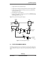
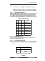
SPI System Errors
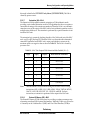
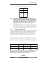
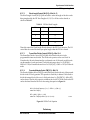
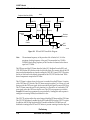
same time. Only an SPI master can experience a mode-fault error. In cases where more
than one device is concurrently configured as a master, a chance of contention between
two pin drivers exists. For push-pull CMOS drivers, this contention can cause
permanent damage. The mode fault attempts to protect the device by disabling the
drivers. When this error is detected, the following actions are taken immediately:
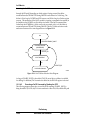
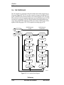
1. The SPI pins are reconfigured as all inputs.
2. The MST control bit is forced to 0 to reconfigure the SPI as a slave.
3. The SPE control bit is forced to 0 to disable the SPI system.
4. The MDF flag is set and an SPI interrupt is generated subject to masking by the
SPIE bit, the appropriate bit in the IPR, and the I1 bit in the SR.
Note:
The SPI pins are reconfigured as inputs regardless of the values of the
corresponding Port C Data Direction Register (PCDDR) bits. This condition is
removed once the SPE bit is set again, and the pins resume their normal SPI
functionality.
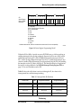
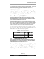
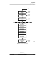
After software has corrected the problems that led to the mode fault, the MDF bit is
cleared and the system returns to normal operation. The MDF bit is automatically
cleared by reading the SPSR while the MDF bit is set, followed by a write to the SPCR.
Other precautions may need to be taken to prevent driver damage. If two devices are
made masters at the same time, mode fault does not help protect either one unless one of
them selects the other as slave. The amount of damage possible depends on the length of
time both devices attempt to act as master.
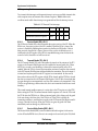
Because the SS pin is used to detect mode fault, it should not be configured as a GPIO
pin on an SPI system where more than one SPI is capable of functioning as an SPI
master. Maintaining the SS functionality can help prevent driver damage if mode fault
occurs.
7.5.2
SPI Write-Collision Error
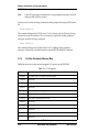
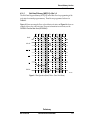
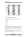
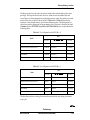
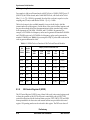
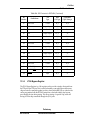
A write-collision error occurs if the SPDR is written while a transfer is in progress.
Because the SPDR is not double-buffered in the transmit direction, writes to the SPDR
cause data to be written directly into the SPI shift register. Because this write corrupts
any transfer in progress, a write-collision error is generated. The transfer continues
undisturbed, and the write data that caused the error is not written to the shifter. A write
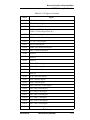
collision is normally a slave error because a slave has no control over when a master
initiates a transfer. A master knows when a transfer is in progress, so there is no reason
Preliminary
MOTOROLA
DSP56824 User’s Manual
7-15