1
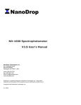
Installation Manual ACURAS System December 2007 SECOND EDITION: MAY 2007 For the ACURAS Software Version 1.1.6.0 or later ©2007 Barco Simulation, LLC 600 Bellbrook Ave. Xenia, OH 45385-4053 USA 1.937.372-7579 telephone 1.937.372.8645 fax 1.800.888.7579 toll-free in USA www.simulation.barco.com This publication and the software described in it are protected under the Copyright Laws of the United States of America. All rights reserved. Reproduction of this material in any form without the express written consent of Barco Simulation, LLC is prohibited. BARCO SIMULATION, LLC PROVIDES THIS DOCUMENT “AS IS” WITHOUT WARRANTY OF ANY KIND, EITHER EXPRESSED OR IMPLIED, INCLUDING BUT NOT LIMITED TO THE IMPLIED WARRANTIES OF MERCHANTABILITY AND FITNESS FOR A PARTICULAR PURPOSE. BARCO SIMULATION, LLC MAY MAKE IMPROVEMENTS AND/OR CHANGES TO THE PRODUCT(S) AND/OR THE PROGRAM(S) DESCRIBED IN THIS PUBLICATION AT ANY TIME WITHOUT NOTICE. This publication could contain technical inaccuracies or typographical errors. Changes are periodically made to the information in this publication; these changes are incorporated in new editions of this publication. Please send comments or questions about this publication directly to Barco Simulation, Publications Department, 600 Bellbrook Ave., Xenia, OH 45385-4053 USA. Trademark Acknowledgment Barco is a registered trademark and the Barco Simulation name is a trademark of Barco Simulation and/or Barco. Other company and product names mentioned in this document may be the trademarks of their respective owners. Notice ACURAS Install Manual.doc Barco Simulation, LLC retains all rights to the data included in this manual. However, permission is granted to copy or duplicate in any manner, the entire contents (in total--not in part) of this manual providing the purpose is solely for personnel training or maintenance of the equipment and also providing this notice and all other proprietary statements are not altered or removed. This notice does not grant any license to manufacture or permit the duplication (in part or whole) of any electronic or mechanical devices or assemblies described in the contents of this manual. ii PROPRIETARY NOTICE: The information contained herein is proprietary to Barco Simulation, LLC, and shall not be reproduced or disclosed in whole or in part, or used for any design or manufacture except when the user possesses direct written authorization from Barco Simulation. Contents Table of Contents 1 INTRODUCTION ....................................................................................................................... 1 Glossary of Terms...................................................................................................................... 2 2 INITIAL SYSTEM SETUP.......................................................................................................... 3 Prerequisite Checklist ................................................................................................................ 4 ACURAS Installation Checklist .................................................................................................. 5 3 INSTALLATION PROCESS ...................................................................................................... 7 4 SOFTWARE/HARDWARE CONTROL VERIFICATION ........................................................... 9 Verifying Gimbal Communication............................................................................................. 10 Testing Gimbal Control ............................................................................................................ 11 Verifying xRACU Communication ............................................................................................ 13 Testing xRACU Projector Control ............................................................................................ 14 Verifying IG Communication .................................................................................................... 15 Testing IG Control .................................................................................................................... 17 Verifying Spectrometer Communication................................................................................... 18 Testing Spectrometer Control .................................................................................................. 19 5 ACURAS SYSTEM DATA SETUP.......................................................................................... 25 System Setup Initialization ....................................................................................................... 26 Setting Black Hole Location .................................................................................................. 27 Setting Number of Channels ................................................................................................. 28 Setting Channel Aim Points .................................................................................................. 29 Clearing Prior Projector Data ................................................................................................ 30 6 ACURAS EXECUTION............................................................................................................ 31 Starting the Software ............................................................................................................... 31 Updating the Projector Configuration ....................................................................................... 33 Calibrating the System ............................................................................................................. 33 Routine Adjustments ................................................................................................................ 34 Recapturing System Targets ................................................................................................... 34 ACURAS Data Storage ............................................................................................................ 34 7 CHROMATICITY CHARTS ..................................................................................................... 35 8 TROUBLESHOOTING ............................................................................................................ 37 iii PROPRIETARY NOTICE: The information contained herein is proprietary to Barco Simulation, LLC, and shall not be reproduced or disclosed in whole or in part, or used for any design or manufacture except when the user possesses direct written authorization from Barco Simulation. List of Figures Figure 1. ACURAS System Components (Typical) ...................................................................................... 1 Figure 2. Initialization Window ...................................................................................................................... 7 Figure 3. ACURAS Installation Tool User Interface...................................................................................... 8 Figure 4. Gimbal Tab – Not Initialized........................................................................................................ 10 Figure 5. Gimbal COM port dialog .............................................................................................................. 10 Figure 6. Gimbal Tab – Initialized ............................................................................................................... 11 Figure 7. Move Gimbal Interface................................................................................................................. 11 Figure 8. xRACU Tab – Not Initialized ........................................................................................................ 13 Figure 9. xRACU Tab – Initialized............................................................................................................... 14 Figure 10. IG Tab – Uninitialized ................................................................................................................ 15 Figure 11. IG IP Address Dialog ................................................................................................................. 16 Figure 12. IG Tab – Initialized ..................................................................................................................... 17 Figure 13. Spectrometer Tab – Not Initialized ............................................................................................ 18 Figure 14. Spectrometer Tab – Initialized ................................................................................................... 19 Figure 15. Integration Time Dialog.............................................................................................................. 20 Figure 16. Spectrum Data on Spectrum Graph .......................................................................................... 21 Figure 17. Spectrum Data on CIE 1931 Chart ............................................................................................ 22 Figure 18. Spectrum Data on CIE 1976 Chart ............................................................................................ 23 Figure 19. System Setup Tab – Not Initialized............................................................................................ 26 Figure 20. System Setup Tab – Initialized .................................................................................................. 27 Figure 21. Set Black Hole Aim Point Dialog................................................................................................ 28 Figure 22. Set Number of Channels Dialog ................................................................................................ 28 Figure 23. Set Channel Aim Point Dialog ................................................................................................... 29 Figure 24. Clear Projector Data Message................................................................................................... 30 Figure 25. ACURAS Initialization Window .................................................................................................. 31 Figure 26. ACURAS User Interface ............................................................................................................ 32 Figure 27. ACURAS User Interface with Log.............................................................................................. 32 Figure 28. Channel To Projector Mapping Dialog....................................................................................... 33 Figure 29. C.I.E. 1931 Chart ....................................................................................................................... 35 Figure 30. C.I.E. 1976 Chart ....................................................................................................................... 36 iv PROPRIETARY NOTICE: The information contained herein is proprietary to Barco Simulation, LLC, and shall not be reproduced or disclosed in whole or in part, or used for any design or manufacture except when the user possesses direct written authorization from Barco Simulation. Introduction 1 Introduction This manual explains how to install the Barco ACURAS system version 1.1.6.0 (or later). The ACURAS system automatically adjusts the selected projector control parameters of the Barco SIM 6 family of projectors (Mk2, Ultra, Ultra II). The ACURAS software is hosted on the projector system’s Master Control Unit (MCU) computer and performs a wide range of the most time-consuming manual adjustments associated with the correction of brightness and color across multiple projectors. ACURAS Gimbal Assembly 74112-100 NOTE: Part number 74112-100 includes the ACURAS Gimbal assembly, USB4000 Spectromer, and USB4000 Spectrometer Cable. Interface Control Unit 06350-100 Rev A NOTE: ICU design may vary based on system configuration. USB4000 Spectrometer USB4000 Spectrometer Cable AC Power Cord V326111 W308 Gimbal Control PT-Cable-UPG-14 Figure 1. ACURAS System Components (Typical) 1 PROPRIETARY NOTICE: The information contained herein is proprietary to Barco Simulation, LLC, and shall not be reproduced or disclosed in whole or in part, or used for any design or manufacture except when the user possesses direct written authorization from Barco Simulation. Glossary of Terms The following defines some commonly used terms and their working definitions as used in association with the ACURAS system. For projector-related terms, please refer to the appropriate projector operator manual. Calibration Lamp: The Ocean Optics LS-1 is a tungsten halogen light source that is used to calibrate the USB2000 spectrometer. Color temperature is 3100° Kelvin. Convergence: The spatial co-alignment of the red, green, and blue dots within a projector, relative to the mean position of the red, green, and blue dots from that projector. Geometry Alignment: The alignment of the spatial positions of dots projected by each projector with respect to their desired positions as defined by a customer-supplied alignment slide projector. Gimbal: The computer-controlled pan tilt unit. Image Generator (IG): The computer that controls the video that is sent to the projectors. Interface Control Unit (ICU): A chassis that contains the gimbal controller, a USB server, and a +5 +24VDC power supply. Pan Tilt Unit (PTU): Commonly referred to as the gimbal. Spectrometer: An instrument designed to measure angles of refraction of light rays. USB4000: Ocean Optics Spectrometer unit. 2 PROPRIETARY NOTICE: The information contained herein is proprietary to Barco Simulation, LLC, and shall not be reproduced or disclosed in whole or in part, or used for any design or manufacture except when the user possesses direct written authorization from Barco Simulation. Initial System Setup 2 Initial System Setup This section provides a checklist for installing the ACURAS software into a system. The prerequisite procedures for performing the ACURAS installation can be found in other documentation, such as the ACURAS Factory Setup Guide, the site-specific wiring diagram, the xRACU Operators Manual, the Polaris Users Guide, and the projector set-up manuals. 3 PROPRIETARY NOTICE: The information contained herein is proprietary to Barco Simulation, LLC, and shall not be reproduced or disclosed in whole or in part, or used for any design or manufacture except when the user possesses direct written authorization from Barco Simulation. Prerequisite Checklist There are various requirements that must occur before the ACURAS system can be installed. These include the initial setup of the ACURAS hardware, the projectors being in a basic state of usability, and the condition of the simulator during the alignment process. The requirements are as follows: Make sure the projector hardware has been properly installed. (Refer to site-specific requirements.) Make sure xRACU software version 4.2.3.0 (or later) has been properly installed to control the projectors in the system. (Refer to the xRACU Operators Manual.) Make sure the projectors have been aligned to be within specification. (Refer to the ATP documents.) Make sure the Polaris software has been properly installed on the IG computer(s). (Refer to the Polaris Setup Guide.) Make sure all ACURAS hardware has been properly installed. (Refer to the ACURAS Factory Setup Guide.) Make sure the ACURAS software and all associated software on the Mass Install disk have been installed. (Refer to ACURAS Factory Setup Guide.) Make sure all system cables are properly connected. (Refer to interconnect documentation for the system.) Caution: Damage may result if certain cables are not connected during power ON. Very important! Verify Fiber Optic cable cannot go below a 4 centimeter bend radius. Make sure all power switches are turned on. Make sure each projector has a unique address. Make sure the projectors are online and operational; they cannot be in standby mode. Make sure a video signal is present for all projectors. Make sure that the gimbal goes through the power-up sequence moments after being powered on. 4 PROPRIETARY NOTICE: The information contained herein is proprietary to Barco Simulation, LLC, and shall not be reproduced or disclosed in whole or in part, or used for any design or manufacture except when the user possesses direct written authorization from Barco Simulation. Initial System Setup ACURAS Installation Checklist The ACURAS installation steps are listed below. More detailed descriptions are available later in this document. Verify gimbal communication and control. Verify xRACU communication and control. Verify IG communication and control. Verify spectrometer communication and control. Set the black hole aim point. Set the number of channels in the system. Set the channel aim points. Update the projector configuration. Calibrate the system. Run routine adjustments once. Optional steps for ATP preparation: Measure the current luminance and color of each channel. Use the xRACU to misadjust dimmers and red-green balance and blue-green balance. Run the routine adjustments to restore the appropriate settings. Measure luminance and color of each channel and compare to the previous values. 5 PROPRIETARY NOTICE: The information contained herein is proprietary to Barco Simulation, LLC, and shall not be reproduced or disclosed in whole or in part, or used for any design or manufacture except when the user possesses direct written authorization from Barco Simulation. This page is intentionally blank. 6 PROPRIETARY NOTICE: The information contained herein is proprietary to Barco Simulation, LLC, and shall not be reproduced or disclosed in whole or in part, or used for any design or manufacture except when the user possesses direct written authorization from Barco Simulation. Installation Process 3 Installation Process This section describes the steps to perform the installation and set up of the ACURAS system. The installation process is separated into three tasks: (1) making all system hardware and software communication functional; (2) Entering the system specific data; and (3) running the ACURAS software to calibrate the system and prepare it for use. 1 Go to the ACURAS install directory. The default location is “C:\Program Files\Acuras”, and launch AcurasInstallationTool.exe. Note: The ACURAS Installation Tool is located in the same directory where the ACURAS software is installed. There are no shortcuts created for this application, because it is only to be used during ACURAS software installation or for major changes to the system. A status window appears as the software attempts to make a number of software and hardware connections. Figure 2 shows the initialization window. Figure 2. Initialization Window Depending on the system state, this window may be present for a few minutes and several error messages may appear. The error messages will provide information on system problems associated with the set up that will need to be corrected to complete the communication verification. 2 Press the OK button for all error messages to continue on. Once the initialization is complete, the Installation Tool Interface appears. Figure 3 shows the ACURAS Installation Tool user interface. 7 PROPRIETARY NOTICE: The information contained herein is proprietary to Barco Simulation, LLC, and shall not be reproduced or disclosed in whole or in part, or used for any design or manufacture except when the user possesses direct written authorization from Barco Simulation. Figure 3. ACURAS Installation Tool User Interface The Installation tool has five tabs that group different installation operations: Gimbal, Spectrometer, xRACU, IG, and System Setup. The first four tabs are used to verify and exercise the communication between the ACURAS system and other hardware and software. The System Setup tab is used to set up system data by the ACURAS system. The signal on each tab is used to show function control and operation. A red signal indicates that the specific installation operation (or tab) has not been successfully initialized and will not function in the current state. A green signal indicates that the specific installation operation (or tab) has successfully initialized and is capable of functioning. The status bar at the bottom of the window indicates the last operation that was executed and the state or result of the operation. 3 To close the application, click the Close box [x] in the upper right-hand corner of the window. 8 PROPRIETARY NOTICE: The information contained herein is proprietary to Barco Simulation, LLC, and shall not be reproduced or disclosed in whole or in part, or used for any design or manufacture except when the user possesses direct written authorization from Barco Simulation. Software/Hardware Control Verification 4 Software/Hardware Control Verification This section describes how to verify the communication parameters for the ACURAS software to ensure proper operation. As mentioned in the previous section, the first four tabs in the ACURAS Install Tool are used to verify system communication. These tabs allow you to test the gimbal and spectrometer hardware operation, communicate with xRACU, and communicate with Polaris software on the image generator. These four tabs can also be used with one another for specific testing of different situations. 9 PROPRIETARY NOTICE: The information contained herein is proprietary to Barco Simulation, LLC, and shall not be reproduced or disclosed in whole or in part, or used for any design or manufacture except when the user possesses direct written authorization from Barco Simulation. Verifying Gimbal Communication The Gimbal tab is used to verify and test control of the gimbal. To verify gimbal communication: 1 Press the Initialize button to attempt to initialize the gimbal. Figure 4 shows the Gimbal tab. The gimbal has not been properly initialized. Figure 4. Gimbal Tab – Not Initialized If the initialization is not successful, an error message appears and provides information to correct the situation. One possible reason for the gimbal failing to initialize is that the COM port settings are incorrect. 2 To change the COM port setting, press the Update Com Port button. A dialog box appears allowing you to select a different COM port. See Figure 5. Figure 5. Gimbal COM port dialog 10 PROPRIETARY NOTICE: The information contained herein is proprietary to Barco Simulation, LLC, and shall not be reproduced or disclosed in whole or in part, or used for any design or manufacture except when the user possesses direct written authorization from Barco Simulation. Software/Hardware Control Verification Testing Gimbal Control After the gimbal initialization has successfully completed, you can test the control of the gimbal. Figure 6 shows the Gimbal tab after the initialization has been successfully completed. Figure 6. Gimbal Tab – Initialized To test gimbal control: 1 Pressing the Move Gimbal button allows you to steer the gimbal to any location. Figure 7 shows the Move Gimbal interface. Figure 7. Move Gimbal Interface 11 PROPRIETARY NOTICE: The information contained herein is proprietary to Barco Simulation, LLC, and shall not be reproduced or disclosed in whole or in part, or used for any design or manufacture except when the user possesses direct written authorization from Barco Simulation. 2 Verify that the gimbal is moving in the direction that the interface suggests. The crosshair shows the current aim location in the full range of motion of the gimbal. Pressing anywhere in the grey panel will move the gimbal to that aim point. 3 Enter specific aim coordinates in the Current Gimbal Position group box and activate with the Move Gimbal button. The Panel Position group box displays the current coordinates of the mouse cursor in the grey panel. 4 Use the directional arrows to make course and fine step adjustments. Select step size adjustments by pressing the center button. Increments are 0.1, 1.0, 10.0, and 20.0 degrees. The status of the gimbal motion is displayed on the Gimbal Status line. Note: Be sure to establish the correct setting for the Ceiling/Floor Mount on the Move Gimbal interface. The system remembers the Move Gimbal setting for future use. The radio button selections will not be present. 12 PROPRIETARY NOTICE: The information contained herein is proprietary to Barco Simulation, LLC, and shall not be reproduced or disclosed in whole or in part, or used for any design or manufacture except when the user possesses direct written authorization from Barco Simulation. Software/Hardware Control Verification Verifying xRACU Communication The xRACU tab can be used to verify and test control of the projectors through the xRACU software. To verify xRACU communication: 1 Press the Initialize button to attempt to initialize xRACU communication. Figure 8 shows the xRACU tab. The xRACU communications link has not been properly initialized. Figure 8. xRACU Tab – Not Initialized If the initialization is not successful, an error message appears that provides information for correcting the situation. One common reason for the xRACU connection initialization failure is that the xRACU software is not in External Mode, a.k.a. IG Control mode. See the xRACU User Manual for information on how to place the xRACU in External Mode. 13 PROPRIETARY NOTICE: The information contained herein is proprietary to Barco Simulation, LLC, and shall not be reproduced or disclosed in whole or in part, or used for any design or manufacture except when the user possesses direct written authorization from Barco Simulation. Testing xRACU Projector Control After the xRACU communication initialization has been successfully completed, you can test the control of the projectors through the xRACU. Figure 9 shows the xRACU tab after the initialization has been successfully completed. Figure 9. xRACU Tab – Initialized To test xRACU projector control: 1 Select the desired Projector(s) using the up or down arrow buttons. You can select a specific projector or all projectors. If the projector number is set to 0, the action will affect all projectors. 2 Press the Pause or UnPause buttons to pause or not pause the projector(s). 14 PROPRIETARY NOTICE: The information contained herein is proprietary to Barco Simulation, LLC, and shall not be reproduced or disclosed in whole or in part, or used for any design or manufacture except when the user possesses direct written authorization from Barco Simulation. Software/Hardware Control Verification Verifying IG Communication The IG tab can be used to verify and test control of the IG image through the Polaris software. To verify IG communication: 1 Press the Initialize button to initialize IG communication. Figure 10 shows the IG tab. The IG communication link has not been properly initialized. Figure 10. IG Tab – Uninitialized If the initialization is not successful, an error message appears that provides information for correcting the situation. One possible reason for the IG communication failing to initialize is that the IP Address settings are incorrect. 2 To change the IP Address setting, press the Update IP Address button. A dialog box appears allowing you to select a different IP Address. See Figure 11. 15 PROPRIETARY NOTICE: The information contained herein is proprietary to Barco Simulation, LLC, and shall not be reproduced or disclosed in whole or in part, or used for any design or manufacture except when the user possesses direct written authorization from Barco Simulation. Figure 11. IG IP Address Dialog 16 PROPRIETARY NOTICE: The information contained herein is proprietary to Barco Simulation, LLC, and shall not be reproduced or disclosed in whole or in part, or used for any design or manufacture except when the user possesses direct written authorization from Barco Simulation. Software/Hardware Control Verification Testing IG Control After the IG initialization has successfully completed, you can test the control of the pattern displayed by the IG. Figure 12 shows the IG Tab after the initialization has been successfully completed. Figure 12. IG Tab – Initialized To test IG control: 1 Press one of the predefined color buttons to select the desired color. The selected color can be seen in the Preview box. 2 Use the Color Select sliders to choose the amount of each primary color to display in the IG output. 3 Once the desired color is selected, press the Display Color Pattern to activate the pattern in the IG. The Now Showing box shows the last successfully loaded color to be displayed by the IG. If the application has no knowledge of the last color, ‘???’ will be displayed in the Now Showing box. 17 PROPRIETARY NOTICE: The information contained herein is proprietary to Barco Simulation, LLC, and shall not be reproduced or disclosed in whole or in part, or used for any design or manufacture except when the user possesses direct written authorization from Barco Simulation. Verifying Spectrometer Communication The Spectrometer tab is used to verify and test control of the Ocean Optics USB2000 spectrometer. To verify spectrometer communication: 1 Press the Initialize button to attempt to initialize the spectrometer. Figure 13 shows the Spectrometer tab. The spectrometer has not been properly initialized. Figure 13. Spectrometer Tab – Not Initialized If the initialization is not successful, an error message appears that provides information for correcting the situation. One possible reason for the spectrometer failing to initialize is that the USB cable is disconnected. During the spectrometer initialization process, a message will appear prompting for the spectrometer to be covered while taking a black measurement. 18 PROPRIETARY NOTICE: The information contained herein is proprietary to Barco Simulation, LLC, and shall not be reproduced or disclosed in whole or in part, or used for any design or manufacture except when the user possesses direct written authorization from Barco Simulation. Software/Hardware Control Verification Testing Spectrometer Control After the spectrometer initialization has been successfully completed, you can test the control of the spectrometer. Figure 14 shows the Spectrometer tab after the initialization has been successfully completed. Figure 14. Spectrometer Tab – Initialized To test spectrometer control: 1 Press the Change Integration Time button to set the integration time at which the spectrometer measurements are to be taken. An integration time dialog box appears allowing you to select an integration time. Each time a new integration time is entered, you’ll need to capture a black spectrum before capturing a new spectrum. Figure 15 shows the Integration Time dialog box. 19 PROPRIETARY NOTICE: The information contained herein is proprietary to Barco Simulation, LLC, and shall not be reproduced or disclosed in whole or in part, or used for any design or manufacture except when the user possesses direct written authorization from Barco Simulation. Figure 15. Integration Time Dialog 2 Press the Capture Black Spectrum button to capture the black measurement and enable the Capture Spectrum button. Each time a spectrum is captured, a window appears showing the information for the spectrometer and the related data capture. The tabs on the spectrum window allow you to see the raw and calibrated spectrum graphs, the location of the color coordinates on the CIE 1931 chart, and the location of the color coordinates on the CIE 1976 chart. 3 Press Close to close the window. If you do not close the window, the graphs will be updated the next time the Capture Spectrum button is pressed. 4 Test the spectrometer readings by combining the functionality of the Spectrometer tab with the functions of other hardware tabs. For example, the xRACU tab can be used to unpause a channel. The Gimbal tab can be used to steer the spectrometer to aim at that channel. The IG tab can display a specific color on the channel. And, the Spectrometer tab can capture the spectrum of the channel. The resulting color coordinates that were read by the spectrometer can then be compared with the color the IG is displaying. Figure 16 shows the spectrum graph. Figure 17 shows the CIE 1931 chart. Figure 18 shows the CIE 1976 chart. 20 PROPRIETARY NOTICE: The information contained herein is proprietary to Barco Simulation, LLC, and shall not be reproduced or disclosed in whole or in part, or used for any design or manufacture except when the user possesses direct written authorization from Barco Simulation. Software/Hardware Control Verification Figure 16. Spectrum Data on Spectrum Graph 21 PROPRIETARY NOTICE: The information contained herein is proprietary to Barco Simulation, LLC, and shall not be reproduced or disclosed in whole or in part, or used for any design or manufacture except when the user possesses direct written authorization from Barco Simulation. Figure 17. Spectrum Data on CIE 1931 Chart 22 PROPRIETARY NOTICE: The information contained herein is proprietary to Barco Simulation, LLC, and shall not be reproduced or disclosed in whole or in part, or used for any design or manufacture except when the user possesses direct written authorization from Barco Simulation. Software/Hardware Control Verification Figure 18. Spectrum Data on CIE 1976 Chart 23 PROPRIETARY NOTICE: The information contained herein is proprietary to Barco Simulation, LLC, and shall not be reproduced or disclosed in whole or in part, or used for any design or manufacture except when the user possesses direct written authorization from Barco Simulation. This page is intentionally blank. 24 PROPRIETARY NOTICE: The information contained herein is proprietary to Barco Simulation, LLC, and shall not be reproduced or disclosed in whole or in part, or used for any design or manufacture except when the user possesses direct written authorization from Barco Simulation. ACURAS System Data Setup 5 ACURAS System Data Setup This section describes how to set up the ACURAS system data for operation on a specific system. The fifth tab in the ACURAS Install Tool is used to setup the system specific data. This tab allows you to set the black hole location, the number of channels in the system, and the spectrometer aim point for the center of each channel, as well as clear all projector information from the ACURAS data file. You can set up the system data once all of the hardware and software connections have been verified. Before proceeding with data setup, be sure to start the ACURAS Installation Tool. Refer to the 3 Installation Process section for more information. 25 PROPRIETARY NOTICE: The information contained herein is proprietary to Barco Simulation, LLC, and shall not be reproduced or disclosed in whole or in part, or used for any design or manufacture except when the user possesses direct written authorization from Barco Simulation. System Setup Initialization The System Setup tab is used to set up the system specific data to be used by the ACURAS software. To set up system initialization: 1 Press the Initialize button on the System Setup tab. Figure 19 shows the System Setup tab. It has not been properly initialized. If the initialization is not successful, an error message appears that provides information for correcting the situation. Figure 19. System Setup Tab – Not Initialized 2 Set the system specific data once the System Setup tab has been properly initialized. Figure 20 shows the System Setup tab after it has been properly initialized. 26 PROPRIETARY NOTICE: The information contained herein is proprietary to Barco Simulation, LLC, and shall not be reproduced or disclosed in whole or in part, or used for any design or manufacture except when the user possesses direct written authorization from Barco Simulation. ACURAS System Data Setup Figure 20. System Setup Tab – Initialized Setting Black Hole Location The black hole is usually located on the gimbal stand, but its location may vary. The ACURAS software must know where to aim the spectrometer for dark measurements. To set the black hole aim point: 1 Press the Set Black Hole Location button on the System Setup tab (refer to Figure 20). The Set Gimbal Position dialog box appears for setting the black hole location. See Figure 21. The gimbal can be steered so that the spectrometer is aiming at the black hole. For more information on the gimbal movement dialog, refer to the Testing Gimbal Control section. Note: The orientation radio selection is no longer available because the interface is using the orientation that was set during the gimbal verification. 2 Aim the spectrometer at the black hole, and then press the OK button. 3 Press Cancel to revert the black hole location to the value that was previously stored. 27 PROPRIETARY NOTICE: The information contained herein is proprietary to Barco Simulation, LLC, and shall not be reproduced or disclosed in whole or in part, or used for any design or manufacture except when the user possesses direct written authorization from Barco Simulation. Figure 21. Set Black Hole Aim Point Dialog Setting Number of Channels The ACURAS software must know the number of channels in the system. To set the number of channels in the system: 1 Press the Set Number of Channels button on the System Setup tab (refer to Figure 20). The channel selection dialog box appears, allowing you to select the number of channels. See Figure 22. 2 Set the number of channels in the system, and then press OK. Pressing Cancel reverts the number of channels to the value that was previously stored. Figure 22. Set Number of Channels Dialog 28 PROPRIETARY NOTICE: The information contained herein is proprietary to Barco Simulation, LLC, and shall not be reproduced or disclosed in whole or in part, or used for any design or manufacture except when the user possesses direct written authorization from Barco Simulation. ACURAS System Data Setup Setting Channel Aim Points The ACURAS software must know where to aim the spectrometer at the center of each channel. To set the channel aim points: 1 Press the Set Channel Aim Points button on the System Setup tab (refer to Figure 20). The Set Gimbal Position dialog box appears, allowing for the gimbal to be steered so that the spectrometer is aiming at the center of each channel. Figure 23 shows the Set Gimbal Position dialog box for setting the channel aim locations. For more information on the Set Gimbal Position dialog box, refer to the Testing Gimbal Control section. Note: The orientation radio selection is no longer available because the interface is using the orientation that was set during the gimbal verification. Figure 23. Set Channel Aim Point Dialog A message appears prompting for the connection of a laser-pointing device to the spectrometer fiber to accurately determine where spectrometer should be aimed. Use this option to ensure the spectrometer is pointing at the desired location. A different dialog appears for each channel. 2 Aim the spectrometer near the center of each channel, and away from all blend regions and edges, and then press the OK button. Pressing the Cancel button reverts the channel aim locations to the values that were previously stored. A final prompt appears reminding you to remove the laser-pointing device and reconnect the fiber to the spectrometer. 29 PROPRIETARY NOTICE: The information contained herein is proprietary to Barco Simulation, LLC, and shall not be reproduced or disclosed in whole or in part, or used for any design or manufacture except when the user possesses direct written authorization from Barco Simulation. Note: Remember the channel numbering scheme that is used. It must match the numbering used in future steps. It is advised to use a common numbering scheme that is employed by the customer and in xRACU to avoid confusion. Clearing Prior Projector Data Note: This function is not required during the installation process. It is merely a facility for clearing corrupted or invalid data. Do not use this option unless you are sure that it is needed. To clear all previous data stored for projectors: 1 Press the Clear Projector Table button on the System Setup tab (refer to Figure 20). A message appears warning that the action will invalidate any previous calibration information for all projectors. See Figure 24. Figure 24. Clear Projector Data Message 2 Press the Yes button to clear the projector data. Note: This will not affect data in the actual projector hardware or xRACU. 30 PROPRIETARY NOTICE: The information contained herein is proprietary to Barco Simulation, LLC, and shall not be reproduced or disclosed in whole or in part, or used for any design or manufacture except when the user possesses direct written authorization from Barco Simulation. ACURAS Execution 6 ACURAS Execution This section describes how to run the ACURAS software to prepare the ACURAS system for routine operation. The ACURAS software is used as a maintenance tool to set up and calibrate the system. The software allows for updating the projector-to-channel relationships, capturing the system target white point and relative luminance, calibrating the projector hardware, and correcting the projector settings to achieve the targets at a later date. Note: You can run the ACURAS software once all of the hardware and software connections have been verified and the system specific data has been set up. Prior to running the ACURAS software, xRACU version 4.2.3.0 (or later) software must be running (projectors powered on) and placed in “External” mode. To activate external mode, go to the xRACU home page and select the IG Control button on the bottom of the screen. Once the external mode is activated, press the Minimize button to see the desktop. Starting the Software To start the ACURAS software: 1 Double-click the ACURAS icon on the desktop. The ACURAS system will go through an initialization process during which it will initialize various software components, communicate with the image generator, and initialize the color sensor/gimbal assembly. Figure 25 shows the initialization window. Figure 25. ACURAS Initialization Window Depending on the system state, the initialization window may be present for a few minutes. Typically, the initialization takes around one minute. If there is a problem with the system, an error message provides information on the situation. The problem needs to be corrected before running ACURAS. The software will then terminate. If a lamp change or projector change occurred since the last time the software was run, warning messages will be displayed indicting there were changes made to the system hardware. 2 Press the OK button to continue through these warnings; they simply indicate that extra steps will be required before the Routine Adjustments can take place. 31 PROPRIETARY NOTICE: The information contained herein is proprietary to Barco Simulation, LLC, and shall not be reproduced or disclosed in whole or in part, or used for any design or manufacture except when the user possesses direct written authorization from Barco Simulation. Figure 26 shows the ACURAS user interface. Figure 26. ACURAS User Interface 3 To view the Log Window and the detailed information on current operations, press the Show Log button. The user interface including the log is shown in Figure 27. Figure 27. ACURAS User Interface with Log 4 To return to the condensed interface, press the Hide Log button. The information in the log can be erased by pressing the Clear button. 32 PROPRIETARY NOTICE: The information contained herein is proprietary to Barco Simulation, LLC, and shall not be reproduced or disclosed in whole or in part, or used for any design or manufacture except when the user possesses direct written authorization from Barco Simulation. ACURAS Execution Updating the Projector Configuration You must update the projector configuration the first time ACURAS is run and any time you replace a projector in the display system. This action will update the stored information on the projector hardware and map a projector to each channel. To update the projector configuration: 1 Press the Update Projector Configuration button on the ACURAS user interface (see Figure 26). The Channel To Projector Mapping dialog appears (see Figure 28). This dialog box allows you to map each projector in the xRACU to a specific channel in the system. Figure 28. Channel To Projector Mapping Dialog 2 Select a channel in the Channel List and cycle through the projectors in the Projector List until the projector that is associated with that channel is found. 3 Press the Map button to map the selected projector to the selected channel. After the channel and projector have been mapped, they will be removed from the lists. The selected projector in the Projector List will be the only projector that is not paused for easy identification. 4 To reset the Channel and Projector lists, press the Reset Mappings button. 5 Press the OK button when all channels have a projector mapped to them. Press the Cancel button to restore any previous mappings that were present. Calibrating the System After you update the projector configuration or change a lamp, you must calibrate the system. The ACURAS software knows which actions need to be performed based on the system state. Typically, these actions will be run with the Run for All Projectors checkbox not checked. If the Run for All Projectors box is checked, the actions will be performed for all channels in the system regardless of their state. If the checkbox is not checked, then the actions will only be performed on the channels that need to be updated. On installation, the result of running this action with and without the checkbox being checked will be the same. The system calibration will capture the new color and luminance targets and 33 PROPRIETARY NOTICE: The information contained herein is proprietary to Barco Simulation, LLC, and shall not be reproduced or disclosed in whole or in part, or used for any design or manufacture except when the user possesses direct written authorization from Barco Simulation. calibrate the color and luminance responses for all required channels. This process takes approximately five minutes per channel. Note: If the targets need to be captured, a warning will be displayed at the start of this process indicating that the system must be aligned at this point. The target color and relative luminance will be restored to the current state of the system. The color and luminance settings must be acceptable at this point or the ACURAS system will not produce acceptable results. NOTE: The spectrometer used by ACURAS measures color with a 3.7nm/pixel resolution over the range of 350-1000nm. ACURAS uses a relative luminance measure. Routine Adjustments The routine adjustment is most common action for the end user. Routine adjustments are performed as needed. The routine adjustments attempt to restore the system to its color and luminance targets. If the luminance can no longer be reached, due to lamp decay, the system luminance will remain matched and decay with the lamp until a replacement is made. This process takes approximately two minutes per channel. Note: Run routine adjustments immediately following a system calibration or a target recapture. If you are planning to run the ACURAS software (ex. for an ATP), make sure to run routine adjustments to ensure the individual luminance targets are properly initialized. Perform routine adjustments prior to misaligning the color and luminance of the system. Recapturing System Targets If you would like to “fine tune” the system color or luminance after ACURAS has been installed, you can use the Recapture System Targets button. This button captures the color and luminance targets for the system. This process takes approximately one minute per channel. Note: At the start of this process, there will be a warning that indicates the system must be aligned at this point. The target color and relative luminance will be restored to the system’s current state. The color and luminance settings must be acceptable at this point or ACURAS will not produce satisfactory results. Note: Run routine adjustments immediately following a system calibration or a target recapture. If you are planning to run the ACURAS software (ex. for an ATP), make sure to run routine adjustments to ensure the individual luminance targets are properly initialized. Perform routine adjustments prior to misaligning the color and luminance of the system. ACURAS Data Storage When an action is completed, the system displays a message that communicates the ACURAS data changes to be saved or undone. If you undo the changes, all ACURAS data will be restored to the state prior to the action, and all xRACU/projector data will be restored to the prior state. If you save the changes, the ACURAS data will be kept. Any changes made to xRACU/projector settings must be saved through the xRACU data interface. 34 PROPRIETARY NOTICE: The information contained herein is proprietary to Barco Simulation, LLC, and shall not be reproduced or disclosed in whole or in part, or used for any design or manufacture except when the user possesses direct written authorization from Barco Simulation. Chromaticity Charts 7 Chromaticity Charts Figure 29. C.I.E. 1931 Chart 35 PROPRIETARY NOTICE: The information contained herein is proprietary to Barco Simulation, Inc., and shall not be reproduced or disclosed in whole or in part, or used for any design or manufacture except when the user possesses direct written authorization from Barco Simulation. Figure 30. C.I.E. 1976 Chart 36 PROPRIETARY NOTICE: The information contained herein is proprietary to Barco Simulation, LLC, and shall not be reproduced or disclosed in whole or in part, or used for any design or manufacture except when the user possesses direct written authorization from Barco Simulation. Troubleshooting 8 Troubleshooting This section lists the error conditions you may encounter during the operation of the ACURAS system, and details the actions you should take to correct the problem. Error Condition Error message: “Failed to connect to xRACU. SocketError: 10061” Corrective Actions 1. xRACU is not running. 2. Start xRACU, enter IG mode, and restart ACURAS. 1. xRACU is not in, or was taken out of, IG mode. Error message: “The connection to xRACU has been closed. Disconnected from host. NOT In External Mode.” 2. Stop ACURAS and put xRACU in external mode. (From the xRACU home page, press the “IG Control” button at the bottom of the screen, then press the “Minimize” button to see the desk top to re-start ACURAS.) A command sent to xRACU has failed. 1. Verify xRACU is running. Error message: “xRACU command ‘XXX’ failed” 2. Verify xRACU is in IG mode. 3. If xRACU or the projectors have recently been upgraded, an incompatibility may have been introduced with the ACURAS software. Determine if there is an ACURAS upgrade available, and upgrade the software. IG communication is not working. Error messages: “The Image Generator Server is not communicating“ “The IG is not responding” “The IG failed to load the requested dot pattern” Any other references to IG communication. 1. Make sure the network cable is securely fastened to MCU, hub, and IG. 2. Make sure that the MCU is set up on the same network as the IG Master. 3. Make sure the hub is turned on and communicating with the MCU and IG. 4. Make sure the IG is properly set up to communicate with the ACURAS system through Polaris. 5. Make sure that the Polaris master and slaves have been started. Gimbal start-up failure. Gimbal did not go through it’s “power up sequence” when AC is applied to GCU 1. Verify GCU AC switch is ON and green indicator is lit. 2. Verify main AC input .5 amp fuse is good. 37 PROPRIETARY NOTICE: The information contained herein is proprietary to Barco Simulation, Inc., and shall not be reproduced or disclosed in whole or in part, or used for any design or manufacture except when the user possesses direct written authorization from Barco Simulation. 3. Verify the AC main power is live. Check site breaker box. 4. Verify cabling to GCU is correct. 5. Remove cover from GCU. Verify gimbal controller power switch is in the ON position. 6. Verify +24VDC. 7. Verify fuse between +24VDC supply and the gimbal controller is good. 8. If AC is good and still no +24VDC, replace +24VDC supply. 9. If +24VDC is present on load side of fuse, replace gimbal controller. Error message: “Failed to initialize Gimbal. Exception: No Gimbal Connection”. Gimbal communication failure. 1. Verify gimbal connection. Any other message that involves the gimbal, PTU, pan, or tilt error. 2. Cycle power on the electronics box. Spectrometer communication. Any message referring to spectrometer or color sensor initialization failure. 1. Verify Ocean Optics drivers have been installed. 2. Verify spectrometer cabling is connected. 3. Verify that calibration files have been installed. Error message: “One or more projectors in the system is/are not powered on.” 1. All projectors in xRACU must be powered on. 2. Restart ACURAS. Error messages: “Unable to find master INI file: sAcuras_Primary_ini_file” Any messages referring to failure to retrieve or write data. Error message: “Color Sensor integration time is at its maximum and cannot produce a result in the desired range.” ACURAS installation has been corrupted. Reinstallation of the software may be necessary. Contact Barco for further guidance and assistance. The image is darker than expected. Dimmer in the projector has malfunctioned or manually set to a low value. 1. Verify projector light is not being obstructed. 2. Make sure projectors are operating. Warning message: “Color Sensor integration time is at its minimum and cannot produce a result in the desired range.” The image is brighter than expected. This is not necessarily an error. For any other error messages Call Barco technical support at 937-372-7579. Make sure that all external light sources are off. 38 PROPRIETARY NOTICE: The information contained herein is proprietary to Barco Simulation, LLC, and shall not be reproduced or disclosed in whole or in part, or used for any design or manufacture except when the user possesses direct written authorization from Barco Simulation. Comments and Suggestions Barco would like to hear your comments and suggestions about the contents of this publication. In fact, we welcome any constructive criticism or questions you may have about this document, or any other Barco technical publications currently in circulation. When contacting us about a particular publication, use this form (attach extra sheets if necessary). Please refer to a publication by its title and date. If possible, please refer to a specific page or paragraph number. We will review your comments, and use them to make improvements to the next edition of that document. Thank you for your interest in Barco products. Title of Publication ___________________________________________________________________ Date of Publication ______________________ Page/Para. No _______________________________ Your comments: From: Name ________________________________________________ Title ________________________________ Date ___________ Barco Simulation 600 Bellbrook Avenue Xenia, OH 45385-4053 USA fax: 937.372.8645 email: [email protected] www.simulation.barco.com Address ______________________________________________ City ______________________ State__________ Zip _________ Telephone ____________________________________________ Email ________________________________________________ Copyright ©2007 Barco Simulation, LLC The information in this manual is subject to change without notice. Produced by Barco Simulation. All rights reserved. All brands and product names are trademarks of their respective companies.


![CAST for PSI user`s manual [v07]](http://vs1.manualzilla.com/store/data/005903758_1-a858c2dfda3ffb28451a6ec48d1cfa02-150x150.png)