1
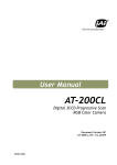
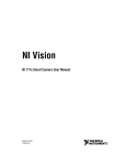
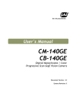
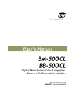
User's Manual CM-200 MCL CB-200 MCL Digital Monochrome / Color Compact Mini-CL Camera Document Version: 1.0 Camera Revision: 0 CM-200 MCL / CB-200 MCL 1. 2. 3. 4. 5. 1. General................................................................................................ 3 2. Camera nomenclature .............................................................................. 3 3. Main Features ........................................................................................ 3 4. Locations and Functions ............................................................................ 4 Pin Assignment............................................................................................ 5 5.1. 12-pin Multi-connector (DC-IN/Trigger) ........................................................... 5 5.2. Digital Output Connector for Mini-CL (Camera Link)............................................ 5 5.3. Input and output circuits ............................................................................ 6 5.3.1. Iris video output ............................................................................. 6 5.3.2. Trigger input ................................................................................. 6 5.3.3. XEEN output .................................................................................. 6 5.3.4. Camera Link interface ...................................................................... 6 6. Functions and Operations ............................................................................... 7 6.1. Basic functions ........................................................................................ 7 6.1.1. Digital Output Bit Allocation............................................................... 7 6.1.2. Electronic Shutter ........................................................................... 7 6.1.3. Continuous operation or triggered operation ........................................... 8 6.1.4. Iris video output ............................................................................. 8 6.1.5. Rear Panel indicator ........................................................................ 8 6.1.6. Auto-detect LVAL–sync / - a-sync accumulation ....................................... 9 6.1.7. Starting pixel – Bayer color mosaic ....................................................... 9 6.1.8. Vertical Binning.............................................................................10 6.2. Sensor Layout and timing...........................................................................11 6.2.1. CCD Sensor Layout .........................................................................11 6.2.2. Horizontal timing ...........................................................................12 6.2.3. Vertical timing ..............................................................................12 6.2.4. Partial Scanning ............................................................................13 6.2.5. Vertical Binning.............................................................................14 6.3. Operation Modes .....................................................................................15 6.3.1. Continuous operation ......................................................................15 6.3.2. Edge Pre-select Trigger Mode ............................................................15 6.3.3. Pulse Width Control Trigger Mode .......................................................17 6.4. Mode and function matrix. .........................................................................18 7. Configuring the Camera ................................................................................19 7.1. CL-seriel control .....................................................................................19 7.2. Setting functions .....................................................................................20 7.2.1. Bit allocation BA=0, BA=1 ................................................................20 7.2.2. Partial scan SC=0 through 4. .............................................................20 7.2.3. Vertical binning VB=0, VB=1............................................................20 7.2.4. Shutter mode SM=0 and SM=1............................................................20 7.2.5. Trigger input select TI=0, TI=1. .........................................................20 7.2.6. Trigger polarity. TP=0, TP=1. ............................................................20 7.2.7. Gain level GA= -84 through +336........................................................20 7.2.8. Black level BL=0 through BL=1023. .....................................................20 7.3. Save and Load Functions............................................................................20 7.4. CM-200MCL/CB-200MCL command list............................................................21 8. Camera Control Tool for CM-200MCL / CB-200MCL ................................................23 8.1. Camera Control Tool Interface ....................................................................23 8.1.1. Camera Control Tool Bar ..................................................................23 8.2. The About Window...................................................................................23 8.3. Communication Window ............................................................................24 8.4. Camera Control Window ............................................................................25 -1– CM-200 MCL / CB-200 MCL 8.5. Using the Camera Control Tool ....................................................................25 External Appearance and Dimensions ................................................................27 Specifications ............................................................................................28 10.1. Spectral response .................................................................................28 10.2. Specification table ...............................................................................29 11. Appendix ..................................................................................................30 11.1. Precautions ........................................................................................30 11.2. Typical Sensor Characteristics..................................................................30 11.3. References .........................................................................................31 12. User's Record .............................................................................................33 9. 10. -2- CM-200 MCL / CB-200 MCL 1. General CM-200 MCL is a monochrome progressive scan CCD camera and CB-200 MCL is the equivalent Bayer mosaic progressive scan CCD camera. Both have 2.0M pixels resolutions. These camera are suitable for a wide range of applications within factory automation, an also for applications outside the factory floor, such as ITS (Intelligent Traffic Solutions), high-end surveillance and medical. The latest version of this manual can be downloaded from: www.jai.com The latest version of Camera Control Tool for CM-200MCL/CB-200MCL can be downloaded from: www.jai.com For camera revision history, please contact your local JAI distributor. 2. Camera nomenclature The standard camera composition consists of the camera main body and C-mount protection cap. The camera is available in the following versions: CM-200 MCL Where C stands for "Compact" family, M stands for "Monochrome", 200 represents the resolution "2 million pixel" and MCL stands for "Mini-CL" interface CB-200 MCL Where C stands for "Compact" family, B stands for "Bayer mosaic color", 200 represents the resolution "2 million pixel" and MCL stands for "Mini-CL" interface 3. Main Features • • • • • • • • • • • • • • • • Compact series 1/1.8 inch progressive scan camera Monochrome and Bayer mosaic color versions 1620 (h) x 1236 (v) active pixels 4.4 µm square pixels 25 frames / second with full resolution in continuous operation 24 frames / second with external trigger and full resolution Up to 99 frames with partial scan 49 frames / second with vertical binning ( CM-200 MCL only ) Shutter speed from 32 µs to 2 second ( 48 frames) using pulse width control Programmable exposure from 64 µs to 40 ms Pre-Select and Pulse Width control trigger modes LVAL –synchronous /-asynchronous operation ( auto –detect ) Power over CL (PoCL) version available Auto iris lens video output allows a wider range of light 10 bit or 8 bit output Set up by Windows NT/Win 2000/ XP via serial communications -3– CM-200 MCL / CB-200 MCL FCC seal 4. Locations and Functions ⑥ 3-M3depth4 (depth0.16) ④ ⑤ POWER/ TRIG MINI-CL ② 1 2 3 4 5 6 Lens mount CCD sensor 26-pin connector 12-pin connector LED Mounting holes 6-M3depth4 (depth0.16) ③ Serial No. ⑥ Caution seal C-Mount ① C-mount (Note *1) 1/2 inch CCD sensor Camera Link Interface (Mini-CL) DC+12V and trigger input (Note *2) Indication for power and trigger input M3 depth 4mm for tripod mount plate *1) Note: Rear protrusion on C-mount lens must be less than 10.0mm. *2) Note: Cameras with the PoCL (Power-over-CL) option do not have the 12-pin connector Fig. 1. Locations -4- CM-200 MCL / CB-200 MCL 5. Pin Assignment 5.1. 12-pin multi-connector (DC-IN/Trigger) Type: HR10A-10R-12PB-01(Hirose) male. Use the part number HR10A-10P-12S for the cable side Fig. 2 Hirose 12-pin connector Pin no. 1 2 3 4 5 6 7 8 9 10 11 12 Signal GND +12 V DC input GND Iris video GND Remarks Only for Continuous mode. TR=0 NC NC GND XEEN out Trigger in DC+12V GND TI=1. Or Camera Link (TI=0). *1) * Note: Factory default is trigger via Camera Link Important note: This camera is also available in a Power over Camera Link (PoCL) version. In this case the 12pin Hirose multi connector is not present on the rear panel. PoCL cameras require special frame grabbers that provide power to the camera via the Camera Link cable. Please consult www.jai.com (3rd party interfacing section) for information on available PoCL frame grabbers. 5.2. Digital Output Connector for Mini-CL (Camera Link) Type: 26 pin SDR connector (3M or Honda type) Mini-CL connector Fig.3. Mini-CL connector Pin No 1,13,14,26 7(+),20(-) 8(-),21(+) 10(+),23(-) 9(-),22(+) 6(-),19(+) 4(-),17(+) 3(-),16(+) 2(-),15(+) 5(-),18(+) -5– I/O I/O O I I O O O O O Name GND RXD TXD Reserve Trigger TxOUT3 TxOUT2 TxOUT1 TxOUT0 TxClk Note DC GND Serial Com. CC1 Ext. Trigger in Camera Link out Clock for CL CM-200 MCL / CB-200 MCL 5.3. Input and output circuits In the following schematic diagrams the input and output circuits for video and timing signals are shown. 5.3.1. Iris video output This signal can be used for lens iris control in Continuous mode. The signal is taken from the CCD sensor output before the gain circuit. The video output is without sync. The signal is 0.7 Vpp from 75 Ω without termination. NOTE: This function is not available in the PoCL version Video Output 75 GND Fig. 4. Video output. 5.3.2. Trigger input Trig input An external trigger input can be applied to pin 10 of 1215k pin #10 pin Hirose connector (when the command TI=1 has been set). The input is AC coupled. To allow long pulses the 1k 100n input circuit is designed as a flip-flop circuit. The leading 68k 75Ω 100k and trailing edges of the trigger pulse activate the circuit. SW302.1 The trigger polarity can be changed by TP=1. 1n GND Trigger input level 4 V ±2 V. The trigger can also be supplied through the Camera Link Fig. 5. Trigger input. connector, when the command TI=0 has been set. NOTE: In the PoCL version trigger can only be applied through the Camera Link connector 5.3.3. XEEN output XEEN is on pin 9 on 12-pin HR connector. The output circuit is 75 Ω complementary emitter followers. It will deliver a full 5 volt signal. Output level ≥4 V from 75Ω. (No termination). EEN is also found in Camera Link. NOTE: In the PoCL version EEN is only available in the Camera Link connector +5V TTL 1k +5V TTL 100 2k2 2 2 75 Pin #9 XEEN output 10k GND Fig. 6. XEEN output 5.3.4. Camera Link interface The digital video is available via Camera Link, with 8 or 10-bit pixel depth, using the CL Base configuration. The digital output signals follow the Camera Link standard using Channel Link chip sets. The data bits from the digital video, FVAL, LVAL, DVAL and EEN are multiplexed into the twisted pairs, which are a part of the Camera Link. Trigger signals and the serial camera control are feed directly through its own pairs. The 26-pin Mini-CL SDR connector pin assignment follows the Camera Link base configuration. For a detailed description of the Camera Link standard, please refer to the Camera Link standard specifications found at the AIA web site, www.machinevisiononline.org. -6- GND CM-200 MCL / CB-200 MCL 6. Functions and Operations 6.1. Basic functions The CM-200 MCL / CB-200 MCL cameras are progressive scan camera with 2 Mega pixels monochrome and Bayer mosaic color CCDs . The interface to the host PC is via digital Mini Camera Link (Mini-CL). Both models output video as 8 bits or 10 bits. The CB-200 MCL outputs raw Bayer video requiring host based color interpolation. An analogue iris video signal can be used for controlling the iris of an auto iris lens when operating in continuous mode. The camera has 2/3, 1/2, 1/4 or 1/8 partial scanning and vertical binning ( CM-200MCL only )for faster frame rates . There are 2 trigger modes in addition to continuous operation . The Edge Pre-Select and Pulse Width Control are available with a unique automatic LVAL sync or a-sync selection function. Below the functions are described in details. 6.1.1. Digital Output Bit Allocation The 10-bit digital output is set 890 LSB as 100% video level when CCD output is 200mV. The white clip level is set at 1023 LSB when CCD output is 230mV. CCD out Black 200mV 230mV Analogue Out Setup 3.6%, 25mV 700mV 800mV Digital Out 32LSB 890LSB 1023LSB 1023 Whi t e Cl i p Level 890 Di gi t al Out [ LSB] 100%Level 32 0 Bl ack Level 25 Anal og Out [ mV] 700 800 Fig.7. Digital Output Bit Allocation 6.1.2. Electronic Shutter CM-200MCL / CB-200MCL camera allows selecting shutter in two ways ; preset shutter (10 fixed steps) and programmable exposure ( in 1251 line period, LVAL increment ). Preset Shutter -7– CM-200 MCL / CB-200 MCL The following 10 steps can be selected by command SH=0 through SH=9. OFF (1/25), 1/60, 1/100, 1/250, 1/500, 1/1000, 1/2000, 1/4000, 1/8000, 1/10000 Programmable Exposure (PE) The Exposure time can be programmed in 32 µs (1 LVAL period) increments. The range is from 2L to 1251L. Minimum shutter speed 2L 32µs x 2(L) = 64 µs Maximum shutter speed 1251L 32µs x 1251 (L) ≈ 40.032ms In vertical binning mode Minimum shutter speed 2L 35.846 µs x 2(L) = 71.692 µs Maximum shutter speed 627L 35.846 µs x 627 (L) ≈ 22.475 ms 6.1.3. Continuous operation or triggered operation The camera can operate in continuous mode applications not requiring asynchronous external trigger. This mode permits the use of a lens with video controlled iris. The camera will operate at its maximum frame rate, 25 frames / second in this mode. For applications that require an external trigger, the camera can accept an external trigger input on pin 10 of the 12-pin Hirose connector or via Camera Link interface. The command “TI” is used to switch between inputs. The camera can operate up to 24 frames / second in triggered operation. 6.1.4. Iris video output The iris video output in pin 4 on the 12-pin Hirose connector is 700 mV for 100% video out in Camera Link. The iris video signal is taken before the gain circuit. It is without sync. The iris video signal can be used for auto iris lens drive in continuous mode. Fig. 8. Iris video output. 6.1.5. Rear Panel indicator The rear panel mounted LED provides the following information: Amber: Power connected - initiating Steady green: Camera is operating in Continuous mode Flashing green. The camera is receiving external trigger -8- CM-200 MCL / CB-200 MCL 6.1.6. Auto-detect LVAL–sync / - a-sync accumulation This function replaces the manual setting found in current JAI cameras. Whether accumulation is synchronous or a-synchronous in relationship to LVAL depends on the timing of the trigger input. When a trigger is received while FVAL is high (during readout), the camera works in LVAL synchronous mode , preventing reset feed through in the video signal. There is a maximum jitter of one LVAL period from issuing a trigger and accumulation starts. When trigger is received when FVAL is low, the camera works in LVAL a-synchronous mode ( No delay ) mode. This applies to both Pre-Select (PS) trigger and Pulse Width (PW) trigger modes. Ext. trigger (2) (1) (3) FVAL (1) In this period camera executes trigger at next LVAL (prevents feed-through noise) (2) Avoid trigger at FVAL transition (+/- 1 LVAL period), as the function may randomly switch between "next LVAL" and "immediate". (3) In this period camera executes trigger immediately (no delay) Fig. 9. Auto-detect LVAL sync /a-sync accumulation 6.1.7. Starting pixel – Bayer color mosaic CB-200MCL is a color camera based on a CCD sensor with a Bayer RGB color mosaic. The color image reconstruction is done in the host PC. The Color sequence in the video signal differs from full scanning to partial scanning. The right hand drawing shows the color sequence at the image start. The start line number is shown from FVAL timing. The start pixel is offset 17 pixels from LVAL when DVAL rises. FVAL Timing Line # from FVAL Actual V Line # 1 Even lines starts with GBG. Odd lines starts with RGR See also chapter 6.3. Partial scan. LVAL 11 1 R G R G B G Full 34 207 R G R G B G 2/3 Partial 49 310 G B G R G R 1/2 Partial 71 464 G B G R G R 1/4 Partial 82 541 R G R G B G 1/8 Partial 1 17 DVAL 16 clock F ig. 10. Bayer color mosaic -9– CM-200 MCL / CB-200 MCL 6.1.8. Vertical Binning This function is only available for CM-200MCL camera. Binning mode (Command VB) is a function where the signal charge from 2 adjacent (vertical) pixels are added together and read out as one pixel. Binning results in half vertical resolution and higher frame rate. By adding 2 pixels together, the sensitivity is doubled. The charge accumulated in 2 adjacent lines is added together in the horizontal CCD register. This is done by providing two pulses to the vertical CCD register for each line readout. Vertical binning can not be used together with the partial scanning. Pixel H Vertical CCD regiser Xsg1 Normal FUll scanning H 2:1 Vertical Binning Video Out Reset S/ H Horizontal CCD Register Fig.11 Vertical Binning - 10 - CM-200 MCL / CB-200 MCL 6.2. Sensor Layout and timing 6.2.1. CCD Sensor Layout The CCD sensor layout with respect to pixels and lines used in the timing and video full frame read out is shown below. For Bayer color sequence, refer to chapter 6.1.7. Fig. 12. CCD sensor layout - 11 – 1 clock = 15.38 ns 1 line = 32 μs CM-200 MCL / CB-200 MCL 6.2.2. Horizontal timing The LVAL period is shown for normal continuous mode. Horizontal Video Timing Full Frame Read out / Partial Read Out 1 LVAL 2080 clk = 32 μs 1 clk = 15.38 ns LVAL OB Valid data OB DATA OUT 48 clk 1628 clk 12 clk OB 392 clk 1688 clk DVAL 1620 clk 4 clk 4 clk Fig. 13. Horizontal timing 6.2.3. Vertical timing The FVAL period for continuous mode full scan is shown. Vertical Video Timing Full Frame Read out Frame rate : 1251L 24.98fps LVAL FVAL 1 2 3 1234 1235 1236 DVAL 3L DATA 10L OB 1236L Valid data CCD Exposure EEN XEEN Fig. 14. Vertical timing for full scan - 12 - 2L OB OB CM-200 MCL / CB-200 MCL 6.2.4. Partial Scanning Partial scan allows higher frame rate by reading out a smaller center portion of the image. This is particularly useful when inspecting objects that do not fill the whole height of the image. Fast-dump period Normal scan period Fast-dump period Vertical Timing The below diagram and table provide vertical timing information for the fixed partial scan settings, 1/2, 1/4, 1/8 and 2/3. Partial Frame Readout LVAL FVAL DVAL 3L DATA CCD Exposure EEN XEEN A C B Values for vertical timing in partial scan continuous mode. AREA FVAL Low (L) A (L) 1/2 3 46 1/4 3 68 1/8 3 79 2/3 3 31 B (L) Start line End line 618 309 924 310 463 773 156 540 696 824 C (L) Total line (L) frame rate (L) 45 712 43.89 67 448 69.75 78 316 98.89 30 888 35.19 206 1030 Remark! The color sequence for CB-200MCL differs in partial scan. Refer to chapter 6.1.7. Fig. 15. Vertical timing for partial scanning - 13 – CM-200 MCL / CB-200 MCL Horizontal Timing The horizontal timing is the same as the full scanning. Horizontal Video Timing Full Frame Read out / Partial Read Out 1 LVAL 2080 clk = 32 μs 1 clk = 15.38 ns LVAL DATA OUT OB Valid data OB 48 clk 1628 clk 12 clk 392 clk 1688 clk DVAL OB 1620 clk 4 clk 4 clk Fig. 16. Horizontal timing for partial scanning 6.2.5. Vertical Binning Vertical binning combines charge from two adjacent lines, reducing the vertical resolution to half and at the same time increasing frame rate and sensitivity. By activating this function, the frame rate is increased to 44.49 fps. This function is available only for CM-200MCL. Important Note Vertical Binning can not be used together with the Partial Scan. Horizontal Timing Horizontal Video Timing V Binning 1 LVAL 2330 clk = 35.846 μs 1 clk = 15.38 ns LVAL DATA OUT OB 12 clk Valid data OB 1628 clk 48 clk 642 clk 1688 clk DVAL 1620 clk 4 clk 4 clk Fig.17. Horizontal Timing for Vertical Binning - 14 - OB CM-200 MCL / CB-200 MCL Vertical timing Vertical Video Timing V Binning Frame rate : 627L 44.492 fps LVAL FVAL 1233+1234 1235+1236 1+2 3+4 DVAL 3L DATA 5L 618L 1L Valid data OB OB OB CCD Exposure EEN XEEN Fig.18. Vertical Timing for Vertical Binning 6.3. Operation Modes This camera can operate in 3 primary modes. 1. TR=0 2. TR=1 3. TR=2 Continuous Mode. Pre-selected exposure. Pre-select Mode. Pre-selected exposure. Pulse Width Control Mode. Pulse width controlled exposure. 6.3.1. Continuous operation For applications not requiring asynchronous external trigger, but should run in continuous operation, this mode is used. For timing details, refer to fig. 13 through fig. 18. To use this mode: Set function: Trigger mode to “Continuous”. Scanning V Binning Shutter mode pre-set or programmable Shutter speed Programmable exp. Other functions and settings TR=0 SC=0 through 4 VB=0, VB=1 SM=0 SM=1 SH=0 to 9 PE=2 to 1252 6.3.2. Edge Pre-select Trigger Mode An external trigger pulse initiates the capture, and the exposure time (accumulation time) is defined by the SH or PE command. The resulting video signal will start to be read out after the selected shutter time. For timing details, refer to fig. 13 through fig. 18 and fig. 19 & 20. - 15 – CM-200 MCL / CB-200 MCL To use this mode: Set function: Trigger mode to “Edge pre-select”. Scanning V Binning Shutter mode to normal or programmable Shutter speed SH=0 to 9 Programmable exp. Other functions and settings Ext. trigger. Camera Link or 12 Hirose Input: TR=1 SC=0 to 4 VB=0, 1 SM=0, SM=1 PE=2 to 1252 TI=0, TI=1 Important notes on using this mode 1. The minimum trigger interval >1 LVAL. 2. Depending on the timing of the leading edge of the trigger pulse in relationship to FVAL, accumulation will be synchronous or a-synchronous in relationship to LVAL. See chapter 6.1.6. for details. LVAL Sync mode timing Tr i g 1L( mi n. ) LVAL 1L( max) CCD Exposur e EEN Exposur e XEEN FVAL Tr i gger i nput wht hi n FVAL HI GH Dur at i on LVAL SYNC Mode Set t i ng 2L Fig. 19. Edge pre-select. LVAL synchronized. LVAL a-SYNC mode timing 4.86 μs ± 1μs Trig 1L( mi n. ) CCD exposure EEN XEEN Exposure time FVAL Trigger input during FVAL LOW period LVAL a-SYNC mode setting Fig.20. Edge Pre-select - 16 - 2L to 3L LVAL a-Synchronized CM-200 MCL / CB-200 MCL 6.3.3. Pulse Width Control Trigger Mode In this mode the accumulation time is equal the trigger pulse width. Here it is possible to have long time exposure. The maximum recommended time is <60 frames. For timing details, refer to fig. 13 through fig. 18 and fig. 21 & 22. To use this mode: Set function: Trigger mode to “Pulse width control”. Scanning V Binning Other functions and settings Ext. trigger. Camera Link or 12 Hirose Input: TR=2 SC=0 to 4 VB=0, 1 TI=0, TI=1 Important notes on using this mode 1. The minimum trigger interval > 1 LVAL 2. Depending on the timing of the leading edge of the trigger pulse in relationship to FVAL, accumulation will be synchronous or a-synchronous in relationship to LVAL. See chapter 6.1.6. for the details. LVAL SYNC Mode timing Tr i g 1L( Mi n. ) LVAL 1L t o 2L 1L( Max) CCD Exposur e EEN XEEN Exposur e FVAL Tr i gger i nput wht hi n FVAL HI GH Dur at i on LVAL SYNC Mode Set t i ng 2L Fig. 21. Pulse width control. LVAL Synchronous. - 17 – CM-200 MCL / CB-200 MCL LVAL a-SYNC mode timing 4. 86 μs ± 1 μs Trig 1L 1L(Min.) CCD exposure EEN XEEN Exposure FVAL Trigger input during FVAL LOW period LVAL a-SYNC mode setting 2L to 3L Fig.22. Pulse Width Control LVAL a-Synchronous 6.4. Mode and function matrix. The following table shows which functions will work in the different modes for CM-200MCL / CB200MCL. Shutter Func. Partial scan V Binning Accumulation LVAL sync / a-sync Iris Video out Yes Yes - Yes Continuos TR=0 Yes Programmabl e Yes Pre-select TR=1 Yes Yes Yes Yes Yes - Pulse Width TR=2 - Yes Yes Yes - Trigger Mode Pre-select Fig. 23. Mode and function matrix. - 18 - CM-200 MCL / CB-200 MCL 7. Configuring the Camera 7.1. CL-serial control All configuration of the CM-200MCL / CB-200MCL camera is done the serial communication in the Camera Link connector. The camera can be set up from a PC running terminal emulator software, or using JAI's camera control software. Below is the description of the ASCII based short command protocol. Communication setting. Baud Rate Data Length Start Bit Stop Bit Parity Xon/Xoff Control 9600 bps 8 bit 1 bit 1 bit None None Protocol. Transmit setting to camera: NN=[Parameter]<CR><LF> (NN is any kind of command. Capital or small letters.) The camera answers: COMPLETE<CR><LF> To have all communication visible on the emulator screen, start with: EB=1<CR><LF> The camera answers: COMPLETE<CR><LF> Transmit request command to camera: NN?<CR><LF> (NN is any kind of command.) The camera answers: NN=[Parameter]<CR><LF> Transmit the following to have the camera actual setting: ST?<CR><LF> The camera answers: A complete list of the current settings Transmit the following to have a command list: HP?<CR><LF> The camera answers: A list with all commands and possible settings Invalid parameters send to camera: (99 is an invalid parameter) SH=99<CR><LF> The camera answers: 02 Bad Parameters!!<CR><LF> To see firmware number. VN?<CR><LF> To see camera ID. It shows the manufacturing lot number. ID?<CR><LF> - 19 – CM-200 MCL / CB-200 MCL 7.2. Setting functions 7.2.1. Bit allocation BA=0, BA=1 This command sets the output for either 8-bit or 10-bit. 7.2.2. Partial scan SC=0 through 4. The CCD scanning format can be selected between full or partial scanning. With partial scanning only the vertical central part of the CCD sensor is read out with a higher frame rate. The partial scan is done by a fast dump read out of the lines in the vertical CCD register down to the top of the partial image. This central part of the image is read out with normal speed. The lines below the partial image are read out and dumped with a high speed. Note: The color sequence for CB-200 MCL differs in partial scan modes. Refer to chapter 6.1.7. 7.2.3. Vertical binning VB=0, VB=1 This function is only for CM-200MCL camera. With Vertical binning the pixel charge from 2 adjacent lines are added together in the horizontal CCD register. This done by providing two pulses to the vertical CCD register for each line readout. Note : Vertical Binning can not be used together with the Partial scanning. 7.2.4. Shutter mode SM=0 and SM=1 With SM=0 this function selects the shutter from the 10 fixed steps (SH=0 through SH=9). With SM=1 from programmable in 1251 steps (PE=2 through PE=1252). 7.2.5. Trigger input select TI=0, TI=1. This function selects the trigger input to be through Camera Link (TI=0), or as TTL through the 12 pin Hirose connector (TI=1). 7.2.6. Trigger polarity. TP=0, TP=1. The active trigger polarity is normal low (TP=0). It can be invert it to active high (TP=1). 6 7.2.7. Gain level GA= -84 through +336. GA=0 is 0dB gain, which is normal working point. The range is from -3 dB to +12 dB. 7.2.8. Black level BL=0 through BL=1023. Black level (or set-up level) will set the video level for black. Factory setting is 32 LSB for 10bit or 8 LSB for 8bit. 7.3. Save and Load Functions. The following commands are for store and load camera settings in the camera EEPROM. Load settings LD - 20 - CM-200 MCL / CB-200 MCL This command will load previous stored settings to the camera. 3 user settings can be stored in the camera EEPROM. 1 factory setting is also stored in the camera. The settings stored in the last used user area is used as default settings at power up. Save Settings SA This command will store the actual camera settings to 1 of the 3 user area in the camera EEPROM. EEPROM Area EA If received, the camera will return the last used user area number. 7.4. CM-200MCL/CB-200MCL command list Command Name Format Parameter Remarks A - General settings and utility commands. EB=[Param.]<CR><LF> EB?<CR><LF> 0=Echo off 1=Echo on 1 Echo Back Off at power up 2 Camera Status Request ST?<CR><LF> Actual setting 3 Online Help Request HP?<CR><LF> Command list 3 digits (e.g) 100 = Version 1.00 4 Firmware Version VN?<CR><LF> 5 Camera ID Request ID?<CR><LF> max 10 characters 6 Model Name Request MD?<CR><LF> max 16 characters 7 User ID UD=[Param.]<CR><LF> UD?<CR><LF> User can save and load free text.(16 or less characters) B – Shutter 1 Shutter Mode SM=[Param.]<CR><LF> SM?<CR><LF> 0=Preset Shutter 1=Programmable exposure 0=Off, 1=1/60, 2=1/100, 3=1/250, 4=1/500, 5=1/1000, 6=1/2000, 7=1/4000, 8=1/8000, 9=1/10000 2 Preset Shutter SH=[Param.]<CR><LF> SH?<CR><LF> 3 Programmable Exposure PE=[Param.]<CR><LF> PE?<CR><LF> 2 to 1252 (CM/CB-200) C - Trigger mode 1 Trigger Mode TR=[Param.]<CR><LF> TR?<CR><LF> 0=Normal (Continuous) 1=Pre-select 2=Pulse Width 2 Trigger Polarity TP=[Param.]<CR><LF> 0=Active Low - 21 – Available when SM=0. Available when SM=1. CM-200 MCL / CB-200 MCL Command Name 3 Trigger Input Format Parameter TP?<CR><LF> 1=Active High TI=[Param.]<CR><LF> TI? <CR><LF> 0=Camera Link 1=Hirose 12pin BA=[Param.]<CR><LF> BA?<CR><LF> 0=10bit 1=8bit Remarks D -Image Format 1 Bit Allocation 2 Scan Format SC=[Param.]<CR><LF> SC? <CR><LF> 0=Full Frame 1=2/3 Partial 2=1/2 Partial 3=1/4 Partial 4=1/8 Partial 3 V-Binning VB=[Param.]<CR><LF> VB?<CR><LF> 0=OFF 1=On Only for CM140MCL E - Gain, Black and signal settings 1 Gain Level GA=[Param.]<CR><LF> GA?<CR><LF> -84 to 336 2 Black Level BL=[Param.]<CR><LF> BL?<CR><LF> 0 to 1023 F - Saving and loading data in EEPROM 1 2 Load Setttings (from Camera EEPROM) Save Settings (to Camera EEPROM) LD=[Param.]<CR><LF> SA=[Param.]<CR><LF> EEPROM Current 3 EA?<CR><LF> Area No Request. 0=Factory area 1=User 1 area 2=User 2 area 3=User 3 area 1=User 1 area 2=User 2 area 3=User 3 area Note : parameter 0 is not allowed 0=Factory area 1=User 1 area 2=User 2 area 3=User 3 area Note : Do not try to use commands not shown in this list. - 22 - Latest used DATA AREA becomes default at next power up. The camera return the latest used DATA AREA. CM-200 MCL / CB-200 MCL 8. Camera Control Tool for CM-200 MCL / CB-200 MCL The camera control Tool for Windows 2000/XP can be downloaded from www.jai.com. The control tool contents a camera control program and a developer’s kit for integrating the control tool in your own software. For the integrator and experienced user, the Camera Control Toll is much more than a program with a window interface. It also provides an easy and efficient ActiveX interface built for MS Windows 2000/XP. The OCX interface has the ability to connect to the camera using the serial interface of the PC by reading and writing properties for the camera. This integration requires simple programming skills within Visual Basic, Visual C++ or similar languages in a Microsoft Windows environment. 8.1. Camera Control Tool Interface The Camera Control Tool Software is based on a main Tool Bar and a number of associated Tool Windows. Each button in the Tool Bar pops up a separate Tool Window when pressed. The layout of the program can be adjusted by arranging the windows the way it is preferred. The program will store this information and recreate this layout, when the program is restarted. All Camera Control Tools have a Communication Window and an About Window. The other window(s) contains camera control commands. 8.1.1. Camera Control Tool Bar This is a Camera Control Tool Bar and when the button of each widow, each control GUI can be initiated. About Window Communication Window Camera Control Window 8.2. The About Window The about window contains information about the version of the program, Internet connection to JAI A/S and access to the help documents. The drop-down List box labelled “ Help File” will list all files, which have the extension .pdf and that are found in the program (default) folder. It is possible to download updated operation manuals from the "downloads" section at the JAI website: http://www.jai.com An updated manual can be saved in the folder address mentioned above and it will automatically be included in the list of help files. - 23 – CM-200 MCL / CB-200 MCL At the bottom of the windows (all windows but the Communication Window is an indicator bar. The bar is green when the Camera Control Tool is connected to a camera and the camera is turned on. The bar is red when the Camera Control Tool is not connected to a camera or when the camera is turned off. 8.3. Communication Window The Communication Window is used to connect the Camera Control Tool with the JAI camera. Camera Link communication: The ’CL Manufacturer/COM-ports’ list box also contains DLL file names (or frame grabber names) for all Camera Link frame grabbers that are installed in the pc. This is done by using a DLL file called "clserial.dll" to upload all frame grabber DLLs that are found in the pc. Just select the option for the frame grabber that is installed in the pc. Auto search Click the auto button to search for a camera on communication port 1 to 16. The camera control program automatically sends camera request on every communication port. The user is prompted to use a communication port if a camera answers the request. Off/On-line mode The Camera Control Tool Application can run Offline (without a camera attached) and all functions are fully functional in offline mode. Off line mode is indicated in The Communication Window, where a status field with graphic and text indicates the on/off-line status. Changing the selected communication port (from the communication window) changes the online/off-line status. If a camera is found on the selected communication port the application runs online otherwise offline. Changing the settings in the application will automatically update the camera settings when the application is online. If the application looses connection with the camera it will automatically go to offline mode and it is indicated in the communication window. Synchronize program and camera The Camera Control software has the ability to synchronize either the camera or the program. Click Synchronize camera to write all settings from the program to the camera or click the Synchronize program to load all settings from the camera to the program. Files When clicking the Write to File or Read from File button, the user is prompted for a file using a standard file dialog. New files are created if they do not already exist. - 24 - CM-200 MCL / CB-200 MCL Files for camera settings have the extension cam. Information about the communication port is not stored in the files. All settings are automatically sent to the camera when a file has been loaded (if the camera is online). Factory and User Settings Use the Store button to store the current camera settings into the user settings area in EEPROM. Current camera settings are not saved when the camera is turned off. To save current camera settings you have to save them on the available user areas. Use the Load button to restore previously saved camera settings from either the Factory or the User EEPROM area. Write All Camera Data to File. Click the “Write Camera Data” button to save all camera settings into a text file. The information that can be saved is: Model Name, Camera ID, User ID, Firmware Version, Current Settings, Factory Settings and the available User Areas. The file is formatted as shown in the picture below: EEPROM Current Area. Click the ‘Get Area’ button to read the power up settings area number. 8.4. Camera Control Window The Camera Control Window contains the fundamental camera setting functions. It is possible to set the shutter mode, Trigger mode, scan format, gain control and black setting. 8.5. Using the Camera Control Tool Here is some practical information about the Camera Control Tool: 1. The Camera Control Tool bar is always on top of other windows. 2. When you minimize the Camera Control Tool bar all open windows will close. 3. It is possible to work with the Camera Control Tool when the camera is online and when the camera is offline. 4. The newer JAI cameras always start up with the last used user area (but for some old models it will start up with the last saved user area.) 5. The Camera Control Tool saves the last used settings (not the user area), which don’t have to be the same as for the last saved user area. 6. The setup file ’CameraName.ini’ stores all information about camera settings. When the program is started the last settings for the program are loaded from the file ’CameraName.ini’ 7. When you turn on the camera and the Camera Control Tool, it is possible that the - 25 – CM-200 MCL / CB-200 MCL Camera Control Tool does not show the actual camera settings (see 4. and 5.). a. To obtain the camera settings click “Synchronize Program”. b. To send the settings that are saved in the Camera Control Tool (last used settings) to the camera click “Synchronize Camera”. c. To see which area the camera has started up in click “Get Area”. - 26 - CM-200 MCL / CB-200 MCL 26 (1.02) FCC seal 9. External Appearance and Dimensions 3-M3depth4 (depth0.16) 5 (0.2) 44 58 (2.28) 66 (2.60) MINI-CL 14.5 (0.57) 29 (1.14) POWER / TRIG C-Mount 50 (1.97) 6-M3depth4 (depth0.16) Serial No. 13 (0.51) Caution seal 26 (1.02) 5 (0.2) Fig. 24. Outline. Note: Cameras with the PoCL (Power-over-CL) option do not have the 12-pin connector. All other parts ar identical. - 27 – CM-200 MCL / CB-200 MCL 10. Specifications 10.1. Spectral response Fig. 25. Spectral response for CM-200MCL Fig.26. Spectral response for CB-200MCL - 28 - CM-200 MCL / CB-200 MCL 10.2. Specification table Specifications CM-200MCL Scanning system Frame rate full frame Pixel clock 31.25kHz (2080 pixels clock/line) Line frequency CCD sensor Sensing area Cell size Active pixels 1/1.8″. Monochrome ICX274AL 1/1.8″ Color ICX274AQ 7.13 (h) x 5.44 (v) mm 4.4 (h) x 4.4(v) μm 1620 (h) x 1236 (v) Pixels in video output. Full 2/3 partial 1/2 partial ¼ partial 1/8 partial Sensitivity on sensor (minimum) 1620 (h) x 1236 (v) 24.98 fps. H = 31.25 kHz 1620(h) x 888 (v) 35.19 fps H= 31.25 kHz 1620 (h) x 712(v) 43.89 fps. H = 31.25 kHz 1620 (h) x 448 (v) 69.75 fps. H = 31.25 kHz 1620 (h) x 316 (v) 98.89 fps. H = 31.25 kHz 0.25 Lux (Max. gain, Shutter OFF,50% video ) S/N ratio 8 or 10 bit in Camera Link Iris video output. Analogue Gain Gamma Synchronization Readout modes Control interface Functions controlled by RS 232C Operating temperature Humidity Storage temp/humidity Vibration Shock EMC Power Dimensions Weight 8 or 10 bit raw Bayer video in Camera Link 0.7 Vpp Manual -3 to +12 dB 1.0 Int. X-tal., External trigger 4 V ±2 V. TTL Via Camera Link TTL Camera Link EEN output Trigger modes Accumulation Preset Shutter speed Programmable exposure Pulse width control Lens mount 0.8 Lux (Max. gain, Shutter OFF,50% Green, w/IR cut filter) More than 50 dB (0dB gain) Digital Video output. Trigger input. CB-200MCL Progressive scan 24.98 frames/sec. Progressive (1251 lines/frame) 65 MHz 4 V from 75 Ω source Pre-Select and Pulse Width LVAL synchronous or a-synchronous automatic selection 9 fixed steps 1/60 to 1/10,000 second 2 L to 1250 L (64 μs to 40.032ms) 1 L to 48 frames. Full, Partial scan.( 2/3,½, ¼, 1/8.) V Binning Full, Partial scan.( 2/3,½, ¼, 1/8.) Camera Link serial Shutter, Trigger, Scanning, Read out, Polarity, Black level, Gain, -5°C to +45°C 20 – 90% non-condensing -25°C to +60°C/20% to 90% non-condensing 10G (20Hz to 200Hz, XYZ) 70G CE (EN61000-6-2 and EN61000-6-3), FCC part 15 class B 12V DC ± 10%. <0.27A ( Normal Operation ) C-mount (Flange back 17.526 mm -0.05mm) Image centre ±0.1mm from C-mount centre 44 x 29 x 66 mm (HxWxD) 115 g 120 g Note: Above specifications are subject to change without notice - 29 – CM-200 MCL / CB-200 MCL 11. Appendix 11.1. Precautions Personnel not trained in dealing with similar electronic devices should not service this camera. The camera contains components sensitive to electrostatic discharge. The handling of these devices should follow the requirements of electrostatic sensitive components. Do not attempt to disassemble this camera. Do not expose this camera to rain or moisture. Do not face this camera towards the sun, extreme bright light or light reflecting objects. When this camera is not in use, put the supplied lens cap on the lens mount. Handle this camera with the maximum care. Operate this camera only from the type of power source indicated on the camera. Power off the camera during any modification such as changes of jumper and switch setting. 11.2. Typical Sensor Characteristics The following effects may be observed on the video monitor screen. They do not indicate any fault of the camera, but do associate with typical sensor characteristics. V. Aliasing When the CCD camera captures stripes, straight lines or similar sharp patterns, jagged image on the monitor may appear. Blemishes Some pixel defects can occur, but this does not have en effect on the practical operation. Cameras are shipped in the condition that CCD spots are not visible. In general, it is said that photo diodes of CCD sensor might damage by influence of cosmic ray and as a result, CCD sensor will have spots. Please pay attention so that camera might not be influenced by cosmic ray on storage and transportation. We also recommend to use sea shipment instead of air flight due to strong influence of cosmic ray to camera. Patterned Noise When the sensor captures a dark object at high temperature or is used for long time integration, fixed pattern noise may appear on the video monitor screen. Caution when mounting a lens on the camera When mounting a lens on the camera dusts particles in the air may settle on the surface of the lens or the image sensor of the camera. It is therefore important to keep the protective caps on the lens and on the camera until the lens is mounted. Point the lens mount of the camera downward to prevent dust particles from landing on the optical surfaces of the camera. This work should be done in a dust free environment. Do not touch any of the optical surfaces of the camera or the lens. Exportation When exporting this product, please follow the export regulation of your own country. - 30 - CM-200 MCL / CB-200 MCL 11.3. References 1. 2. 3. 4. This manual can for CM/CB-200MCL can be downloaded from www.jai.com Datasheet for CM/CB-200MCL can be downloaded from www.jai.com Camera control software can be downloaded from www.jai.com Specifications for the CCD sensor Sony ICX274AL and ICX274AQ can be found on www.jai.com - 31 – CM-200 MCL / CB-200 MCL Index Bayer mosaic color, 3, 7 Binning, 1, 10, 15, 22 Binning mode, 10 Bit allocation, 1, 22 Black level, 1, 22, 31 Blemishes, 32 Camera Control Tool, 1, 3, 25, 26, 27, 28 Camera Link, 1, 4, 5, 6, 7, 9, 17, 18, 21, 22, 24, 26, 31 Camera Link connector, 6 CCD sensor, 4 Continuous operation, 3, 7, 16 External trigger, 3, 6, 8, 9, 16 Gain, 6, 9, 22, 27, 31 Gamma, 31 Hirose, 5, 6, 8, 9, 17, 18, 22, 24 Lens mount, 4, 31 Mini-CL connector, 5 Partial scanning, 7, 10, 14, 15, 22 Pixels in video output, 31 PoCL, 3, 6 Preset shutter, 8 Programmable exposure, 8 Progressive scan, 3, 7 Scanning format, 22 Spectral response, 30 Synchronization, 31 Trigger input, 1, 4, 6, 22, 31 Trigger polarity, 6, 22 Vertical binning, 3, 7, 8 XEEN, 1, 5, 6 - 32 - CM-200 MCL / CB-200 MCL 12. User's Record Camera type: CM-200 MCL / CB-200 MCL Revision: …………….. Serial No. …………….. Firmware version. …………….. For camera revision history, please contact your local JAI distributor. User's Mode Settings. User's Modifications. DECLARATION OF CONFORMITY AS DEFINED BY THE COUNCIL DIRECTIVE 89/336/EEC EMC (ELECTROMAGNETIC COMPABILITY) WE HEREWITH DECLARE THAT THIS PRODUCT COMPLIES WITH THE FOLOWING PROVISIONS APPLYING TO IT. EN61000-6-2 EN61000-6-3 Company and product names mentioned in this manual are trademarks or registered trademarks of their respective owners. JAI A-S cannot be held responsible for any technical or typographical errors and reserves the right to make changes to products and documentation without prior notification. Europe, Middle East & Africa Asia Pacific Americas Phone +45 4457 8888 Fax +45 4491 8880 Phone +81 45 440 0154 Fax +81 45 440 0166 Phone (toll-free) +1 800 445 5444 Phone +1 408 383 0300 Visit our web site at www.jai.com - 33 – CM-200MCL Supplement The following statement is related to the regulation on “ Measures for the Administration of the control of Pollution by Electronic Information Products “ , known as “ China RoHS “. The table shows contained Hazardous Substances in this camera. mark shows that the environment-friendly use period of contained Hazardous Substances is 15 years. 嶷勣廣吭並㍻ 嗤蕎嗤墾麗嵎賜圷殆兆各式根楚燕 功象嶄鯖繁酎慌才忽佚連恢匍何〆窮徨佚連恢瞳麟半陣崙砿尖一隈〇云恢瞳ゞ 嗤蕎嗤 墾麗嵎賜圷殆兆各式根楚燕 〃泌和 桟隠聞喘豚㍉ 窮徨佚連恢瞳嶄根嗤議嗤蕎嗤墾麗嵎賜圷殆壓屎械聞喘議訳周和音氏窟伏翌 亶賜融延、窮徨佚連恢瞳喘薩聞喘乎窮徨佚連恢瞳音氏斤桟廠夛撹冢嶷麟半 賜斤児繁附、夏恢夛撹冢嶷鱒墾議豚㍉。 方忖仝15々葎豚㍉15定。 CB-200MCL Supplement The following statement is related to the regulation on “ Measures for the Administration of the control of Pollution by Electronic Information Products “ , known as “ China RoHS “. The table shows contained Hazardous Substances in this camera. mark shows that the environment-friendly use period of contained Hazardous Substances is 15 years. 嶷勣廣吭並㍻ 嗤蕎嗤墾麗嵎賜圷殆兆各式根楚燕 功象嶄鯖繁酎慌才忽佚連恢匍何〆窮徨佚連恢瞳麟半陣崙砿尖一隈〇云恢瞳ゞ 嗤蕎嗤 墾麗嵎賜圷殆兆各式根楚燕 〃泌和 桟隠聞喘豚㍉ 窮徨佚連恢瞳嶄根嗤議嗤蕎嗤墾麗嵎賜圷殆壓屎械聞喘議訳周和音氏窟伏翌 亶賜融延、窮徨佚連恢瞳喘薩聞喘乎窮徨佚連恢瞳音氏斤桟廠夛撹冢嶷麟半 賜斤児繁附、夏恢夛撹冢嶷鱒墾議豚㍉。 方忖仝15々葎豚㍉15定。