1
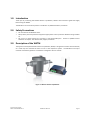
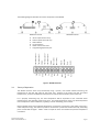
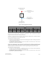
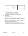
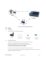
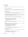
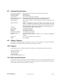
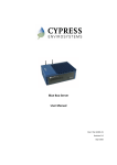
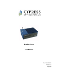
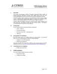
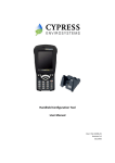
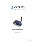
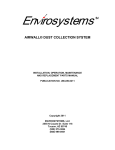
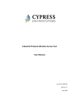
Wireless Steam Trap Monitor
User Manual
Doc # 152-10104-01
Revision 1.1
November 2009
Copyrights
Copyright 2008 by Cypress Envirosystems, Inc. All rights reserved.
The information in this document is subject to change without notice. While reasonable precautions have been
taken, Cypress Envirosystems assumes no responsibility for any errors that may appear in this document. No part
of this document may be copied or reproduced in any form or by any means without the prior written consent of
Cypress Envirosystems.
Disclaimer
CYPRESS ENVIROSYSTEMS MAKES NO WARRANTY OF ANY KIND, EXPRESS OR IMPLIED, WITH REGARD TO THIS
MATERIAL, INCLUDING, BUT NOT LIMITED TO, THE IMPLIED WARRANTIES OF MERCHANTABILITY AND FITNESS FOR
A PARTICULAR PURPOSE. Cypress Envirosystems reserves the right to make changes without further notice to the
materials described herein. Cypress Envirosystems does not assume any liability arising out of the application or
use of any product or information described herein. Cypress Envirosystems does not authorize its products for use
in mission or safety critical systems or where a malfunction or failure may reasonably be expected to result in
significant injury to the user. The inclusion of Cypress Envirosystems’ product in mission or safety critical system
applications implies that the manufacturer assumes all risk of such use and in doing so indemnifies Cypress
Envirosystems against all charges. In no event is Cypress Envirosystems liable to anyone for any indirect, special or
consequential damages.
Table of Contents
1.0
2.0
3.0
4.0
5.0
6.0
7.0
8.0
9.0
10.0
11.0
Introduction ........................................................................................................................ 4
Safety Precautions .............................................................................................................. 4
Description of the WSTM.................................................................................................... 4
3.1
Theory of Operation................................................................................................ 5
3.2
Connections ............................................................................................................ 7
3.3
Sample Collection ................................................................................................... 7
3.4
Cypress Envirosystems Monitoring System ............................................................ 8
3.5
Related Products..................................................................................................... 8
Setup ................................................................................................................................... 9
4.1
Components............................................................................................................ 9
4.2
Installation Overview .............................................................................................. 9
Operation .......................................................................................................................... 10
5.1
Configuration ........................................................................................................ 10
5.2
Turning the WSTM On and Off ............................................................................. 10
5.3
Setting Sampling Rates ......................................................................................... 10
5.4
WSTM Configuration Mode .................................................................................. 10
Care and Maintenance...................................................................................................... 11
6.1
Calibration............................................................................................................. 11
6.2
Battery Life............................................................................................................ 11
Troubleshooting................................................................................................................ 11
Technical Specifications .................................................................................................... 12
Product Disposal ............................................................................................................... 12
Support ............................................................................................................................. 12
Warranty Information....................................................................................................... 12
1.0 Introduction
Thank you for purchasing this Wireless Steam Trap Monitor, WSTM. Please read this guide thoroughly
before using the WSTM.
The WSTM is not a stand-alone product. See Section 3.5, Related Products, for details.
2.0 Safety Precautions
•
•
•
Do not immerse the WSTM in water.
Always wear personal protective equipment appropriate to the system the WSTM is being installed
on.
Do not try to repair yourself as it contains no user-serviceable parts. Contact a qualified service
technician for repairs. See Section 10.0, Support, for details.
3.0 Description of the WSTM
The Cypress Envirosystems Wireless Steam Trap Monitor, WSTM, is designed to monitor the functionality
of a steam trap and transmit the data to a PC or data acquisition system. The WSTM has two input
channels and is battery powered. Installation is designed to be non-invasive.
Figure 1. Wireless Steam Trap Monitor
Cypress Envirosystems
Doc # 152-10104-01 Rev 1.1
WSTM User Manual
Page 4
The following diagram describes the various components of the WSTM.
B
C
F
A
E
D
WSTM Front Panel
Aux In
Aux In
Gnd
Gnd
Batt Out
Batt Out
Batt In
Batt In
(Not used)
Opt2
(Not used)
Opt1
Shield
Shield
Thermocouple 2 Ch2-
Thermocouple 2 +
Ch2+
Shield
Shield
Ch1-
Ch1+
Thermocouple 1 -
Sensor input terminal strip
External power terminal strip
LED indicators
Function button
Radio antenna connector
Programming/Expansion port
Thermocouple 1 +
A.
B.
C.
D.
E.
F.
WSTM Back Panel
Figure 2. WSTM Schematic
3.1
Theory of Operation
The WSTM monitors steam trap functionality using a proven, time tested method measuring the
temperature at the inlet and outlet of the steam trap. Analysis of the steam trap inlet and outlet
temperatures, as well as the differential temperature, indicate the functionality of the steam trap.
For a properly functioning trap, the inlet temperature will be equivalent to the saturated steam
temperature for the operating pressure set point. The outlet temperature of the trap will be equivalent
to the temperature of the condensate, typically just under the boiling point of water.
Note: Expected steam and condensate temperature are functions of pressure. If the outlet of the trap is
under backpressure (e.g. the steam trap outlet is connected to a pressurized condensate tank), the boiling
point of water will be higher. Table 1 shows a sample of steam and condensate pressure-temperature
correlations.
Cypress Envirosystems
Doc # 152-10104-01 Rev 1.1
WSTM User Manual
Page 5
Saturated Steam Inlet
at X pressure
Inlet Temperature
Approx. saturated steam temperature
at X pressure
STEAM
TRAP
Outlet Temperature
Less than boiling point of water
at Y backpressure
Condensate Outlet
with Y Backpressure
Figure 3. Steam Trap Operation Schematic
Saturated Steam
Condensate
Pressure
Temperature
Backpressure
Boiling Point of Water
psig
bar
°C
°F
psig
bar
°C
°F
50
3.4
138
281
14.7
1
100
212
100
6.9
164
328
20
1.4
109
228
150
10.3
181
358
30
2.1
121
250
Table 1. Steam and Condensate Pressure-Temperature Correlation
Steam traps have two failure modes – failed open or failed closed. Table 2 summarizes the expected
temperature profile for the failure modes of a steam trap.
Failed open. A failed open steam trap indicates a blown trap that is leaking steam. This failure mode can
result in increased energy costs due to the loss of steam.
The indicators for this failure mode are:
• The steam trap outlet temperature is greater than the boiling point of water, indicating the presence
of steam on the outlet of the trap.
• The differential temperature between the inlet and outlet of the steam trap is less than the
differential for a properly functioning trap.
Failed closed. A failed closed steam trap indicates a blocked trap that is building up condensate in the
system. Condensate buildup in a steam system can reduce the efficiency of the steam generation system.
Additionally, significant condensate buildup can also lead to pipe damage caused by water hammer.
The indicators for this failure mode are:
• The steam trap inlet temperature is significantly lower than the saturated steam temperature,
indicating the presence of condensate on the inlet of the trap.
• The differential temperature between the inlet and outlet of the steam trap is less than the
differential for a properly functioning trap.
Cypress Envirosystems
Doc # 152-10104-01 Rev 1.1
WSTM User Manual
Page 6
Scenario
Inlet Temperature
Outlet Temperature
Functioning Trap
At saturated steam temperature
Just below the boiling point of water
Blown Trap
At or above saturated steam
temperature
Above the boiling point of water
Blocked Trap
Below boiling point of water
Below the boiling point of water
Off or Bypassed Trap
Ambient temperature
Ambient temperature
Table 2. Steam Trap Temperature Profiles
3.2
Connections
The WSTM has two pre-defined channels for data collection, and one channel for calculation.
• Channel 1 monitors the temperature at the inlet of the steam trap.
• Channel 2 monitors the temperature at the outlet of the steam trap.
• Channel 3 calculates the differential temperature across the steam trap.
The WSTM inputs are pre-configured at the factory and cannot be changed during use.
3.3
Sample Collection
Samples are collected one of three ways.
Manual instantaneous reading. The user can physically collect a reading at the WSTM.
Routine data collection. A routine sampling interval between 1 and 65000 seconds can be programmed
into the WSTM. When the WSTM is on, this is the default sampling interval that data will be collected.
Pre-programmed short term data collection intervals. Each WSTM comes with two pre-programmed data
collection intervals. These are short term intervals of data collection that override the routine data
collection rate. They are intended to be used for troubleshooting, or during known events when the user
might want to change the sampling rate for a short period of time.
See Section 5.0, Operation, for detailed instructions for setting sample collection rates.
The reading value is then transmitted wirelessly as part of the overall Cypress Envirosystems Monitoring
System.
Cypress Envirosystems
Doc # 152-10104-01 Rev 1.1
WSTM User Manual
Page 7
3.4
Cypress Envirosystems Monitoring System
The Cypress Envirosystems Wireless Transducer Reader is part of the Cypress Envirosystems Monitoring
System. This system can be setup one of two ways:
Figure 4. Cypress Envirosystems Monitoring System Setup Options
3.5
Related Products
The WSTM sends data to our Blue Box Server, which stores the data in a SQL server. The WSTM can
communicate directly to the Blue Box Server, or through Wireless Range Extenders.
Cypress Envirosystems
Doc # 152-10104-01 Rev 1.1
WSTM User Manual
Page 8
Wireless Steam Trap
Monitor
(WSTM)
Blue Box Server
(BBS)
Wireless Range Extender
(WRE)
Figure 5. Cypress Monitoring System Overview
4.0 Setup
4.1
Components
The WSTM comes with the following components:
WSTM
Thermocouples
4.2
External power
connector
Sensor input
connector
Installation Overview
Installation of the WSTM is designed to be non-invasive to production operations.
Mount the unit in close proximity to the steam trap to be monitored.
Connect the thermocouple clamps on the inlet and outlet of the steam trap.
Connect the inlet thermocouple to Channel 1 of the WSTM.
Connect the outlet thermocouple to Channel 2 of the WSTM.
Please note, installation of the WSTM must be performed by a qualified technician.
For safety reasons, personal protective equipment should always be worn during installation of the
WSTM, due to the presence of live steam.
Cypress Envirosystems
Doc # 152-10104-01 Rev 1.1
WSTM User Manual
Page 9
5.0 Operation
5.1
Configuration
Configuration of the WSTM must be performed by a qualified technician. See Section 10.0, Support, for
details.
5.2
Turning the WSTM On and Off
To turn on a WSTM, connect the external power terminal connector. When the device is first powered
on, the LED lights will turn on in sequence. To turn off the WSTM, disconnect the external power terminal
connector.
5.3
Setting Sampling Rates
Manual instantaneous reading. To take a one-time reading, press the Function button for less than 2
seconds. The green LED light will flash to indicate that data has been collected.
Routine data collection. Whenever the WSTM is on, it samples based on the routine data collection rate.
This rate is between 0 and 65535 seconds, or approximately 18 hours. This value is defined by the user,
but can only be changed using the Handheld Configuration Tool.
Preprogrammed short term data collection intervals. In addition to the routine data collection rate, there
are two pre-programmed short term data collection intervals associated with the WSTM.
FAST
The FAST sample mode collects data at a 5-second interval for a 5-minute duration. The WSTM can be
placed into the FAST sample mode using the Function button.
1. Press the Function button. The green LED will illuminate.
2. Hold the Function button until the yellow LED illuminates.
3. Release the Function button.
To cancel the FAST sample mode once it has been initiated, press the Function button. The yellow LED
will flash, to indicate that the sample mode has been cancelled.
MEDIUM
The MEDIUM sample mode collects data at a 30-second interval for an 8-hour duration. The WSTM can
be placed into the MEDIUM sample mode using the Function button.
1. Press the Function button. The green LED will illuminate.
2. After two seconds, the yellow LED will also illuminate.
3. Hold the Function button until the red LED illuminates.
4. Release the Function button.
To cancel the MEDIUM sample mode once it has been initiated, press the Function button. The yellow
LED will flash, to indicate that the sample mode has been cancelled.
5.4
WSTM Configuration Mode
The Configuration mode is primarily restricted and for use by qualified service technicians to configure
and install the WSTM.
The WSTM can be placed into the Configuration mode using the Function button.
1. Press the Function button. The green LED will illuminate.
2. After two seconds, the yellow LED will illuminate.
Cypress Envirosystems
Doc # 152-10104-01 Rev 1.1
WSTM User Manual
Page 10
3.
4.
5.
After an additional two seconds, the red LED will illuminate.
After an additional two seconds, all three LED lights will flash.
Then release the Function button. The green LED light will continuously flash.
To exit from the Configuration mode, press the Function button. The LED lights will no longer flash.
6.0 Care and Maintenance
6.1
Calibration
The WSTM is calibrated during installation and initial configuration. Routine calibration can be performed
and verified by a qualified service technician, but is not required. See Section 10.0, Support, for details.
6.2
Battery Life
The battery status of the WSTM can be monitored through the web console. Battery change-out must be
performed by a qualified service technician. See Section 10.0, Support, for details.
The battery life of the WSTM is dependent on the sampling frequency. Typical ranges are listed below.
Sampling Frequency
1 sample per 1 minute
1 sample per 15 minutes
1 sample per hour
1 sample per day
Estimated Battery Life
1.5+ years
3+ years
3+ years
3+ years
7.0 Troubleshooting
My reading on the web console does not match the transducer display.
Please verify that the min and max values were set properly on the Cypress Envirosystems Web Console.
If you have any additional problems, please contact us. See Section 10.0, Support, below for details.
Cypress Envirosystems
Doc # 152-10104-01 Rev 1.1
WSTM User Manual
Page 11
8.0 Technical Specifications
Steam Trap Compatibility
Max Steam Pressure
Data Capture Rate
Thermocouple
Max Thermocouple Length
Wireless Frequency
Wireless Range
Wireless Protocol
Approvals
Power Supply
Battery Life
Humidity
Operating Temperature
Storage Temperature
Enclosure
Dimensions
Weight
All mechanical steam traps, 1/2" (12.5mm) steam line and up
800 psi (55 bar)
User-configurable
Type K, 32°F to 2012°F (0°C to 1100°C)
5ft (1.5m) standard length. Custom lengths available upon request.
2.4GHz Direct Sequence Spread Spectrum, 100mW peak output
Up to 1600 ft (488 m), high interference immunity, extendable with
repeaters
Cypress Semiconductor's highly optimized industrial DSSS radio and
protocol. Integrates robust security, antenna and frequency diversity,
optional encryption and minimal interference with existing wireless systems
(for additional details, please see FAQ at www.cypressenvirosystems.com)
FCC Class B compliant, RoHS, ETSI compliant
Two 3V lithium batteries
>3 years (approximate)
10-99%RH, non-condensing
-4°F to 158°F (-20°C to 70°C)
-40°F to 185°F (-40°C to 85°C)
Rugged extruded aluminum industrial chassis (optional NEMA4/IP66
enclosure)
5.7” x 2.2” x 1.6” (145mm x 57mm x 42mm)
0.51 lbs (230g)
9.0 Product Disposal
The WSTM is recycled by Cypress Envirosystems. Contact a service technician or Cypress Envirosystems
headquarters to recycle the WSTM. See Section 10.0, Support, for details.
10.0 Support
For additional support, including configuration, maintenance, and troubleshooting, please contact us.
Cypress Envirosystems, Inc.
198 Champion Court
San Jose, CA 95134
+1 888 987 3210
Email: [email protected]
11.0 Warranty Information
Every product comes with a full one-year parts and labor warranty. Cypress Envirosystems monitoring of
battery status, product status, and potential communications packets are included during this period, so
that proactive service can be provided to our customers.
Cypress Envirosystems
Doc # 152-10104-01 Rev 1.1
WSTM User Manual
Page 12