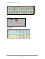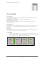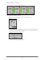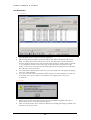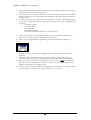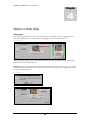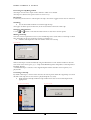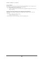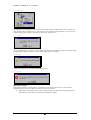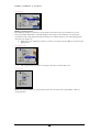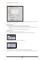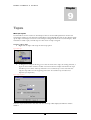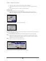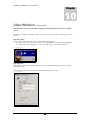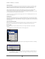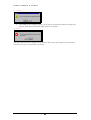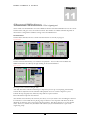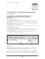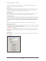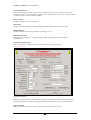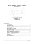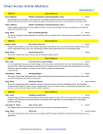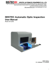
1
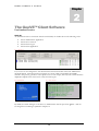
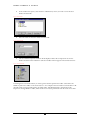
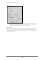
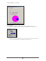
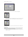
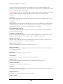
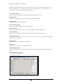
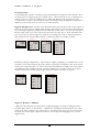
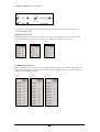
GEE BROADCAST SYSTEMS LTD GeeVS Server Manual Server & Client GEE BROADCAST SYSTEMS LTD GeeVS Server Manual – Server and Client Version 4.2.0.8 No part of this publication may be reproduced, stored in a retrieval system, or transmitted, in any form or by any means, electronic, mechanical, photocopying, recording or otherwise, without the permission of Gee Broadcast Systems Ltd. ® ® Matrox , DigiSuite and DigiServer™ are registered trademarks of Matrox Electronic Systems Ltd. ® ® Intel and Pentium are registered trademarks of Intel Corporation ® ® ® ® Windows , Windows 98 , Windows 2000 and Windows NT are registered trademarks of Microsoft Corporation ® Sony is a registered trademark of Sony Electronics Inc. ® Louth is a registered trademark of Harris Corporation All other nationally and internationally recognised trademarks and trade names are hereby acknowledged Disclaimer Gee Broadcast Systems Ltd. reserves the right to make changes to specifications and procedures at any time and without prior notice. Whilst every attempt has been made to ensure that the information contained within this document is accurate, no responsibility is assumed by Gee Broadcast Systems Ltd. for its use, nor for any third party infringements of patents or other rights resulting from its use. No licence is granted under any patent or patent rights held by Gee Broadcast Systems Ltd. © Gee Broadcast Systems Ltd Unit 9 Grafton Way • Basingstoke • Hants • RG22 6HY • UK Phone +44 (0)1256 810123 • +44 (0)1256 810061 G E E V S S E R V E R & C L I E N T Table of Contents Chapter1 Introduction 02 Chapter2 The GeeVS™ Client Software 03 Chapter3 Record a Clip 07 Chapter4 Make a Sub Clip 11 Chapter5 Make a Sequence 14 Chapter6 Playout a Clip or a Sequence 19 Chapter7 Folders Window 22 Chapter8 Search for a clip, or clips 29 Chapter9 Tapes 32 Chapter10 Clips Window 35 Chapter11 Channel Windows 38 Chapter12 Sequence Windows 39 Chapter13 The GeeVS™ Administrator Program 40 Chapter13 User Manager 48 Chapter15 GeeVS Client Preferences 49 Chapter16 Troubleshooting and Support 51 AppendixA Supported Hardware 52 1 G E E V S S E R V E R & C L I E N T Chapter 1 Introduction The GeeVS™ range of Clip Servers offers configurations from simple single Channel units up to multi-Channel systems using GaSSS™ (Gee-Advanced-Shared-Storage-Solution) SAN fibre Channel storage in a multi-workstation environment. The system uses the Windows™ NT/2000/XP platform and Matrox® DigiSuite™ hardware. Operational control is provided by the GeeVS™ Client Software User Interfaces running on the host Server, remotely over a network, via the Internet or by means of the GeeVS™ Shotbox control panel. The system may also be operated by automation systems from various manufacturers using ethernet or serial connection using protocols such as Sony® RS422 or Louth® This User Manual details the operational procedures available using the GeeVS™ Client Software User Interface and the GeeVS™ Shotbox. Information on operation from an automation system will be available from the suppliers of that automation system. The GeeVS Administrator, which configures the system, is also covered in this Manual, see chapter 12. Whilst most of the operational functions of the GeeVS™ Software Interface are intuitive, it is in the interests of the user to familiarise themselves with the content of this Manual to obtain the quickest route to maximum productivity with the system. Within this Manual, all visual references will be taken from a four Channel GeeVS™. This serves to illustrate all functions, and specific references to other configurations will be clearly indicated. A separate manual covers GeeVS version 1. 2 G E E V S S E R V E R & C L I E N T Chapter 2 The GeeVS™ Client Software User Interface Overview Start-Up As default GeeVS Server and Client will start automatically on machine boot in the following order: GeeVS Administrator Application GeeVS Server Console GeeVS Client Logon GeeVS Client Application. Fig. 1 Administrator If your server is not configured to Auto-Start then the Start GeeVS button in GeeVS Administrator should be clicked. This will open the GeeVS Server Console window and initialise all available channels. This process generates a video splash-screen on each output, and only when each channel has displayed its Splash Screen is the Server ready for Client logons. Fig. 2 Splash Screen Fig. 3 Server Console By default, the Client will logon to the Server as Administrator with the password “geevs”. This can be changed in User Manager explained in Chapter 14. 3 G E E V S S E R V E R & C L I E N T Fig. 4 Client Logon Main Screen display The main elements of the GeeVS™ Software Interface are detailed below. Their use and relevance to operational functions will be covered within later chapters of this publication. Clip Edit Window Channels window Fig. 5 GUI Folders Window Sequence Window 4 Clips Window G E E V S S E R V E R & C L I E N T Folders Window Fig. 6 Tree View All Clips This is the master Clip store, where all video Clips on the disks are viewed. Within this section, there will also be Clip Folders. These are user-defined and are used for media management purposes. Searches Searches are used for the quick location and retrieval of stored Clips and to speed up the process of making Tapes and Sequences. Tapes Virtual Tapes are used in VTR replacement mode. Virtual Tapes are controlled via Remote Control using Sony RS-422 protocol. Sequences Sequences are used for multiple Clip playback with loop and event controls. Current Folder Shown as a blue icon, the Current Folder is where any newly captured Clips will appear. These will still be displayed within All Clips, and Folders are merely an organisational method. is where Clips are being Note: Current Folder is where Clips will be stored; an open Folder viewed. Sub Clips will be saved to a location determined in Client Preferences. See Chapter-15 Fig. 7 Make Current Clips Window The information displayed within the Clips Window is dependent upon the nature of the Directory or Folder being viewed and is fully detailed in the relevant section of this publication. Channels Window This Window displays the currently available Channels within GeeVS™ and their status. Each Channel has an assigned colour, which can be seen in the top right hand corner, and is used as a visual indication within the Clip and Sequence Windows indicating which Channel a Clip has been loaded to. 5 G E E V S S E R V E R & C L I E N T Fig. 8 Channel Window Clip Edit Window This Window displays and controls the Clip currently being edited. Fig. 9 Edit Window Sequence Window Fig. 10 Sequence Window 6 G E E V S S E R V E R & C L I E N T Chapter 3 Record a Clip Recording Clips The recording capabilities of the system are dependent upon the hardware configuration and may not be configured for some installations. Recording Clips within the GeeVS™ environment offers three capture modes: Record Clips with VTR control Using VTR control with Sony RS422 protocol, IN and OUT points can be set and the Clip is automatically recorded. Record from a list Using VTR control with Sony RS422 protocol, a list of IN and OUT points can be set. A list may also be saved for future use, or loaded from a file. The Clips in the list are then automatically recorded sequentially. Record "live" If no VTR control is available to record from a camera or other "live" source, then a crash recording can be made. This can have a preset duration or be open ended. To Record Clips Take control of the Channel you wish to record, by clicking the Channel Lock icon. This will activate the Channel and the icon will turn red to indicate that it is currently in use. Other stations on the network will see details of who is using the Channel. Fig. 11 Channel 1 selected for control 7 G E E V S S E R V E R & C L I E N T Fig. 12 – Channels 1 & 2 in use by “Administrator”, Channel 3 under local control Recording Clips From VTR or Live Source Right click on the Channel and select Record from the dropdown menu. Fig. 13 Record A warning dialogue will appear indicating that you are about to enter E-E (live) mode. Select Yes or No to confirm. This option can be toggled in Preferences. Any Clip that is playing out of the Channel will stop when switched to record. Fig. 14 Warning The Record Box will open. (see The Record Box) 8 G E E V S S E R V E R & C L I E N T The Record Box Fig. 15 Record Box Hit Add/Mark button to add an item in the capture list. Edit the Clip Name, Description and the Duration of the Clip. If the Duration Box is left blank, recording will continue until the user cancels. The Clip Name entered will form the basis for all Clips captured in this session and the Clips themselves will be named sequentially i.e. if a Clip Name of Goal is entered, the Clips, as captured will be named Goal, Goal1, Goal2, etc. The name of the Clip currently being captured will be displayed in the Clip Name Box and may be altered if desired. Use VTR enables/disables RS422 control of a connected VTR deck. The display will change when Use VTR is disabled. If you have no Deck Control enabled GeeVS™ will warn you that No Remote Control will be available. If you do have Deck Control and this error appears, please check your connections. Fig. 16 No VTR SDTI Capture enables faster than real-time capture with SDTI compatible decks. Speed options are from 1x to 4x normal (real-time) speed. Video and Audio Tracks can be enabled or disabled for recording. Recording is enabled when the button is in the down state. 9 G E E V S S E R V E R & C L I E N T The VTR Controls mimic the physical controls of the VTR deck, including the action of the horizontal shuttle control above the buttons. In and out points are set with the Mark button. After an out point is set, the next time Mark is clicked, an in point for a new Clip will be set automatically. Clips will be added sequentially to the Capture List. To load a pre-saved record Tape log, click the Load button. A window will open allowing you to navigate to the Directory where the Tape log has been previously saved. Compatible Tape log files are: o Avid Media log files o Gee Tape log files o Incite IML files o Pebble Beach Playlists and can be selected from the ‘Files of type’ dropdown. Capture List properties can be edited by clicking on the relevant field and typing the new value. You can change the Name and Tape In and Out points. Cueing a Clip is accomplished by right clicking on the relevant field and selecting Cue. Fig. 17 Cue To delete an entry in the Capture List, highlight the entry and press the delete key on the keyboard. The Capture List can be backed up by using the Save button. Files can be saved as the following: Tapelog file types; Gee Tape log files; Incite IML files; Pebble Beach Playlists. When you are ready to Capture the List, press the red record button . You will then be given the option of capturing all of the Clips or a selection. Use the standard Windows™ CTRL key method to select multiple entries. Overwrite Clips when checked allows existing clip names and media to be overwritten. When an existing clip is overwritten the new clip is assigned a new server ID. 10 G E E V S S E R V E R & C L I E N T Chapter 4 Make a Sub Clip Editing Clips Before any Clip can be edited, it must first be loaded into the Clip Edit window by dragging it from either the Clips Window or a Channel Box and dropping it onto the Clip Edit window. Fig. 18 Drag to Edit Once the required Clip is present in the Clip Edit window, the editing controls become active and the Channel shows the Editing Clip status. Warning: Moving a clip from a Channel Box will cause playback for that channel to stop. You will be warned that doing this will interrupt any playback from the channel; and given the opportunity to abort the operation by pressing No. Fig. 19 Warning Fig. 20 Loaded 11 G E E V S S E R V E R & C L I E N T Previewing the Clip Being Edited The Clip is viewed on the output of the Channel to which it was loaded. The Clip to be edited can be previewed in one of two ways: Play/Pause Use the Play/Pause button to roll and pause the Clip. The button toggles between the two functions Scrubbing Use the horizontal Scrub Bar to scrub through the Clip The Upper scrub bar represent fine trim, the Lower Scrub bar controls the whole clip. Setting In and Out Points Use the and buttons or the IN and OUT buttons to select the in and out points. Making a Sub Clip Once the in and out points have been set, the marked Clip can be saved either as a Sub Clip or a Real Clip, depending on the user preferences setting (see Chapter 15). Click the Sub Clip button and enter a name for the new sub clip. Fig. 21 Sub Clip When a Sub Clip is created automatically using the Mark button on the channel window it takes the same name as the master, plus (1), i.e. a Clip named BrazilGP_Finish will produce a Sub Clip named BrazilGP_Finish1. A Virtual Sub-Clip is a reference to the original Clip file and the selected in and out points, not a physical file. Converting a Sub Clip By default a Sub Clip is “virtual” and it references in and out points within the original clip. To break this ’link’ a Sub Clip can be converted to a physical Clip file very easily. Right click the Sub Clip within the Clips window then select Convert Sub Clip from the popup menu. Fig. 22 Convert Subclip Fig. 23 Exported 12 G E E V S S E R V E R & C L I E N T Setting a Mini Pic The image shown for the Clip in the Clip, Channel and Clip Edit Windows can be a snapshot of any frame within the Clip that acts as a reminder of the Clip contents. Select the chosen frame within the Clip. Click the Set Mini Pic button. The mini pic has been grabbed and will be used as the browse image for the Clip. Grabbing a Frame (only available in some configurations See Appendix A) Video frames may be 'grabbed' as graphical files for other purposes and are saved as a 32 bit .tga (Targa) file Select a suitable frame within the Clip. Click the Grab Frame button. The frame will be saved on the hard disk as selected in the Dialogue Box. 13 G E E V S S E R V E R & C L I E N T Chapter 5 Make a Sequence What are Sequences? Sequences are collections of Clips to be played in order with additional functionality, allowing the inclusion of manual control of the Play Sequence and automated 'jumping' within the Sequence. Creating a New Sequence Right click on Sequences and accept the New Sequence option. Fig. 24 New Sequence The New Sequence will be created automatically, with the name New Sequence, and will be displayed within the Folders window. The newly created Sequence is ready for renaming to something more meaningful. Enter a new name as required, then press Enter. Compiling a Sequence Sequences can be compiled manually or by converting a Search into a Sequence (see Converting a Search to a Sequence). To compile a Sequence manually: Drag and drop Clips from anywhere within the Clips Window to the chosen Sequence in the Folders Window. Fig. 25 Drag to Sequence The new Sequence will be created automatically in the order in which the Clips were added. This order may be changed by dragging and dropping Clips within the Sequence (see Modifying a Sequence). 14 G E E V S S E R V E R & C L I E N T Converting a Search to a Sequence Searches can easily be converted to Sequences, thereby allowing for continuous playback of all the selected Clips. Right click the Search you wish to convert to a Sequence and select the Make Sequence option from the popup menu. Fig. 26 Make Sequence The new Sequence will be created automatically and will be given the same name as the Search from which it was created. Exporting a Search Searches can easily be exported to any one of GeeVS supported plug-in formats. Right click the Search you wish to export and save the list. Fig. 27 Select Sequence The New Sequence will be now be visible in the Folders Window and can be renamed if required (see Renaming an Existing Sequence). Modifying a Sequence A Clip in a Sequence can be removed, re-ordered and edited, even whilst the Sequence is live. To re-order a Clip, simply drag and drop the Clip to its new location. Fig. 28 Move Clip in Sequence To delete a Clip, highlight its icon, right click and select Delete from the popup menu. This will only delete the Clip from the Sequence, not from the disk. 15 G E E V S S E R V E R & C L I E N T Fig. 29 Delete Clip Inserting a Goto in a Sequence Right click the destination clip in the Clips Window and select the Insert Goto Function from the popup menu. Fig. 30 Insert Goto A Goto icon will appear in the bottom of the Sequence. Fig. 31 Goto Icon The Goto will loop from the end of the Sequence to the Clip where the insert Goto was selected. The Goto can be dragged to another location in the Sequence, if required, and will retain its Goto reference. Fig. 32 Goto in List 16 G E E V S S E R V E R & C L I E N T To Insert An Event in a Sequence An Event is like a break within a Sequence. Events separate Clips in a single Sequence into groups so that they can be controlled as individual Sequences within the main Sequence. Right Click in the Sequence where you want the Event, and select the Insert Event option from the popup menu. Fig. 33 Insert Above An Event Properties dialogue will appear. Label allows you to enter a name for the Header, Automatic will automatically play through the Event and Manual will stop the Sequence when it reaches an event and wait until the user starts the Sequence again. “GPI” function is not supported in this version. Manual – Stops the sequence at each event after it and waits until the user re-starts the sequence by pressing the next button for the channel. Wait Till – Allows the sequence to ‘hold’ and wait for a user-defined time before playing the next clip. Wait For – Allows the sequence to ‘hold’ and wait for a user-defined number of frames before playing the next clip AutoPlay – Cancels the previous Event property. Fig. 34 Trigger Type When a Sequence is playing, the current Clip will be highlighted with a colour bar. This colour bar corresponds to the Channel it is playing to i.e. Channel1 = Green, Channel2 = Blue, Channel3 = Yellow, Channel4 = Pink, etc. A Clip will be greyed out if it is scheduled to be played next. A greyed bar means the Clip cannot be edited, re-ordered or deleted. Renaming an Existing Sequence Existing Sequences can easily be renamed to ease their use in the future. Click on the Sequence you wish to rename. The Sequence will be highlighted. Click again on the Sequence name, to enter edit mode. Type a new name as required and press Enter. The renamed Sequence will now be visible in the Folders Window. 17 G E E V S S E R V E R & C L I E N T Deleting a Sequence Sequences can be deleted when they are no longer required. Right click on the Sequence you wish to delete and select Delete from the popup menu. A dialogue box will appear, allowing you to continue with the deletion or abort the process. Fig. 35 Load Sequence A warning dialogue comes up to prevent accidental deletion. Fig. 36 Warning 18 G E E V S S E R V E R & C L I E N T Chapter 6 Playout a Clip or a Sequence Loading a Clip to a Channel Clips and Sub Clips can be run directly from within Channels and have to be loaded into the selected Channel to be played. This can be accomplished in two ways: Drag and drop the required Clip (or Sub Clip) from the Clips Window into the selected Channel. OR Right click the required Clip and select the Load option from the popup menu. Another popup menu will appear listing the available Channels. The number of Channels available is dependent upon the hardware configuration. Fig. 37 Load to Channel OR Hold the CTRL and TAB keys together, type the clip ID at the prompt and select F1 –F8 on the keypad. The F Key number corresponds to the channel order, for example, F1 is the first channel, F2 is for the second and so on. Fig. 38 Clip ID Clip Run-Mode When a Clip is loaded to a Channel, it automatically either cues or plays depending on the Channel Status. The Channel Status can be changed by right clicking on the Channel. Selecting Autoplay will cause clips to automatically play when loaded into the channel. Deselecting it will cause the loaded clip to cue and wait for the play button to be pressed. The Channel Window shows the Clip name and countdown clock. A colour highlight in the Clip Window indicates the Clip being played. 19 G E E V S S E R V E R & C L I E N T Fig. 39 Run Mode Fig. 40 Loaded If the currently playing clip is in the Clip window, then the clip will be highlighted the same colour as assigned to the channel. Loading a Sequence to a Channel Like Clips and Sub Clips, Sequences are run from within Channels and have to be loaded into the selected Channel. This can be accomplished in two ways: Drag and drop the required Sequence from the Folders Window into the selected Channel. OR Right click the required Sequence and select the Load option from the popup menu. Another popup menu will appear listing the available Channels. The number of Channels available is dependent upon the hardware configuration. Fig. 41 Right Click Load Sequence Run-Mode When a Sequence is loaded to a Channel, it automatically displays a Sequence Window and reflects the status in the Clip Window. The colour highlight indicates the Clip being played and automatically moves through the list. 20 G E E V S S E R V E R & C L I E N T Fig. 42 Sequence Preview If a manual Event is encountered, the Sequence will stop and continue when triggered. When a Sequence is playing the current Clip will be highlighted with a colour bar. This colour bar corresponds to Channel its playing to i.e. Channel1 = Green, Channel2 = Blue, Channel3 = Yellow, Channel4 = Pink, etc. A Clip will be greyed-out, if it is scheduled to be played next. A greyed bar means the Clip cannot be edited, re-ordered or deleted. 21 G E E V S S E R V E R & C L I E N T Chapter 7 Folders Window -Organise your Media Working with Directories and Folders Defining Directories and Folders Unlike a conventional PC, a GeeVS™ Clip Server has, effectively, two file structures. The physical structure of data on the disks is the same as the normal Windows™ structure of Drives, Directories, Sub-Directories and Files. In addition, the GeeVS has a 'Virtual' structure that resembles the physical but consists merely of references to the stored data, rather than the actual data itself. It is this 'Virtual' structure that is displayed within the Folders Window of the GeeVS™ Software Interface, thereby providing easy access to the stored media without the complications of the underlying Drive and Directory structure. In use, the presence of the two structures is transparent to the user and is only relevant during the processes of creating new Folders and Directories. Within this Manual and the software interface, the terms Directory (icon ) and Folder (icon ) will be used to represent both the physical and Virtual structures respectively. Original Configuration When supplied, the GeeVS™ will have only the very basic Directory and Folder structure, allowing for the users to create whatever configuration suits their method of working. Fig. 43 Default Folders may be created, renamed, copied and deleted easily to create a flexible and efficient structure. It should be borne in mind that whilst Folders can be deleted from within the GeeVS™ software interface, directories cannot. Therefore, it is wise to only create new Directories when really necessary for efficient storage. Directories may be deleted from within the Windows™ environment. Creating a Folder Creating a Folder within GeeVS™ is a simple, four step, process: Right click on All Clips to create the Folder and select Add Folder from the popup menu to create the Folder. Fig. 44 Add Folder 22 G E E V S S E R V E R & C L I E N T In the window that opens, select the drive and Directory where you wish to store the New Folder and click OK. Fig. 45 New Folder Enter the name for the New Folder and click OK. Fig. 46 Name Folder The New Folder Properties window will be displayed. Select the compression rate for the Folder and click on the OK button. The New Folder will now appear in the Folder structure. Fig. 47 Inserted Folder If working from a networked client you must type the absolute path for the folder. This will be the Windows path to the folder on the GeeVS Server. For example if the GeeVS Servers media drive is M: then this needs to be input followed by the folder name, M:\MyNewFolder. This function only imports an existing Windows folder, folder creation can only be performed from the local server client. 23 G E E V S S E R V E R & C L I E N T Fig. 48 Properties The compression standard will have been set under GeeVS™ Administrator and cannot be mixed within a single GeeVS™ chassis. The available compression options are dependent upon the hardware configuration of the GeeVS™. See Appendix A. Folder Properties Right click on a folder and select Properties. There are two tabs, General and Capacity. General displays folder name and compression whilst Capacity displays Disk Space in Hours:Min:Sec based upon the folders compression. This takes in to consideration the default 20% overhead needed for the system to perform correctly 24 G E E V S S E R V E R & C L I E N T Fig. 49 Capacity Renaming a Folder Renaming Folders is a straightforward process and can be achieved in either of two ways; Right click on the Folder you wish to rename and select Properties from the popup menu. Fig. 50 Properties Within the newly opened Properties window, type a new name in the Label window and click OK. The renamed Folder will now be displayed in the Folder structure. 25 G E E V S S E R V E R & C L I E N T Fig. 51 Folder Name OR Click on the Folder that you wish to rename. The Folder will be highlighted. Fig. 52 Rename Wait a short time then Click on the highlighted Folder name again. The Folder name will now show a bounding box and there will be a flashing cursor at the right of the Folder name. Fig. 53 Rename Type a new name for the Folder and press Enter. The Renamed Folder will now be displayed in the Folder structure. Deleting a Folder WARNING: Deleting a Folder is a destructive process - Clips contained within the deleted Folder will not be recoverable from the Recycle bin if they are permanently deleted. User privileges will determine whether you can delete Clips. Right click on the Folder that you wish to delete and select Delete from the popup menu. A dialogue box will open. 26 G E E V S S E R V E R & C L I E N T Fig. 54 Delete Folder The dialogue box will ask if you want to delete the Folder from the database. This does not delete the Clips from the disk, it simply removes the reference to the Folder from the database. If you select Yes, another dialogue box will open. Selecting No aborts the delete process. Fig. 55 Warning The second dialogue box will give you the option of permanently deleting the Clips in the Folder. Make an appropriate selection. If ‘No’ is selected, another dialogue box will open. Fig. 56 Warning Confirm the deletions at the third and final dialogue box Fig. 57 Warning Refreshing a Folder Refreshing a Folder is a useful practice, especially in a networked environment, to ensure that the displayed contents accurately reflect the current status of the Folder. Right click on the Folder that you wish to Refresh and select Refresh from the popup menu. The Folder contents will be refreshed and available for display. 27 G E E V S S E R V E R & C L I E N T Fig. 58 Refresh Making a Folder Current Recorded Clips will be stored in the Current Folder and saved into the relevant Directory on the selected hard disk. Remember, "All Clips" displays all the Clips on the hard disks. Any Sub Clips created from these Clips will be stored in the location set within Preferences, the default being 'Same As Parent'. See chapter 15 Right click on the Folder into which you wish to save Clips, and select Make Current from the popup menu. Fig. 59 Make Current The original Folder icon will now change to the blue, Current Folder, icon. Fig. 60 Current Note: The Current Folder is a saving location and is not the same as the Open Folder, which is a viewing location. 28 G E E V S S E R V E R & C L I E N T Chapter 8 Search for a clip, or clips What are Searches? Searches are a fast and convenient method for gathering related Clips together, provided they have been named in a logical manner. The method employed follows the familiar Windows™ method and allows for a Search to be carried out on any combination of fields: Clip Name, Description, Agency, Category, Aspect Ratio, Duration, Expired, and will allow for partial words to be found. An example of a two-field Search might be to Search for Clips named Win, in the Formula-1 Folder, that have a description containing Schu. This will return all Clips that were in the Formula-1 Folder, are named Wins, Winning, winner, wind in his hair, etc., and have Schummy, Schumacher, schumaker, etc. in the Description field. Any Clips having a blank Description field would be ignored. A Search could also be made for all Clips of less than 10 seconds Duration, by leaving the Name and Description fields blank and setting the Duration to be between 0 and 250 frames (assuming 25 frames/sec PAL). Creating a New Search Right click on Searches and accept the New Search option Fig. 61 New Search A dialogue box will open allowing you to Search in a particular section (defaults to All Clips), and enter a name or description to Search for. Following normal Windows™ practice, leaving a field blank will result in all Clips meeting the other Search criteria being located. 29 G E E V S S E R V E R & C L I E N T Fig. 62 Search Properties Once the Search has been completed, the results will be displayed in the Clips window and the Search will be displayed in the Folders window. Renaming a Search Searches can easily be renamed to ease their future recovery and reuse. Click on the Search you wish to rename. The Clip will be highlighted. Click again on the Search name to enter edit mode. Type a new name as required and press Enter. The renamed Search will now be visible in the Folders Window. Deleting a Search Searches can be deleted when they are no longer required. Right click on the Search you wish to delete and select Delete from the popup menu Fig. 63 Delete Search A warning dialogue comes up to prevent accidental deletion Fig. 64 Warning Converting a Search Searches can be converted to Tapes or Sequences to provide additional capabilities. Right click on the Search you wish to convert and select the appropriate option from the popup menu. 30 G E E V S S E R V E R & C L I E N T Fig. 65 Make Tape The new Tape or Sequence will be created automatically and will be given the same name as the Search from which it was created. The new Tape or Sequence will be now be visible in the Folders Window, under the relevant Tape or Sequence directory. For further information see Chapter 5, How to make a Sequence or Chapter 9, Tapes. 31 G E E V S S E R V E R & C L I E N T Chapter 9 Tapes What are Tapes? GeeVS™ allows for the creation of 'Virtual Tapes' that are used in VTR replacement mode. Each Virtual Tape will have its own timecode, independent of the individual timecode on the Clips that make up the Tape. Virtual Tapes consist of a series of Clips at designated timecodes. GeeVS will “play” black and silence if asked to play a Virtual Tape at a time where no Clip is assigned. Creating a New Tape Right click on Tapes and accept the New Tape option Fig. 66 New tape A dialogue box will open allowing you to enter the name of the Tape, the starting timecode, a figure for the number of frames of black to be inserted between Clips and whether the Tape should loop or not. Note: The loop function is not a seamless loop. At the end of the last Clip, the Tape will Cue to the beginning and restart. If a seamless loop is needed use a Sequence (see Sequences). Fig. 67 Tape Properties Enter the required information and click OK. The new Tape will be displayed within the Folders Window 32 G E E V S S E R V E R & C L I E N T Compiling a Tape Tapes can be compiled manually or by converting a Search into a Tape (see Converting a Search to a Tape). To compile a Tape manually: Drag and drop Clips from anywhere within the Clips Window to the chosen Tape in the Folders Window. Fig. 68 Drag to Tape The new Tape will consist of the Clips, in the order in which they were dropped, separated by frames of black if this option was set when the Tape was created. Unlike Sequences, the order of the Clips on a Tape cannot be changed once it is loaded to a Channel. If changes are required then the Virtual Tape will need to be unloaded, changed and reloaded to the desired Channel. Converting a Search to a Tape Searches can easily be converted to Tapes, thereby allowing for continuous timecode to be placed across all the Clips selected. Right click the Search you wish to convert to a Tape and select the Make Tape option from the popup menu. Fig. 69 Search to Tape The New Tape will be created automatically and will be given the same name as the Search from which it was created. Fig. 70 Tape Created The New Tape will be now be visible in the Folders Window and can be renamed if required (see Renaming a Tape). Renaming a Tape Tapes can easily be renamed to ease their use in the future. 33 G E E V S S E R V E R & C L I E N T Click on the Tape you wish to rename. The Tape will be highlighted. Click again on the Tape name to enter edit mode. Type a new name as required and press Enter. The renamed Tape will now be visible in the Folders Window. Deleting a Tape Tapes can be deleted when they are no longer required. Right click on the Tape you wish to delete and select Delete from the popup menu. A dialogue box will appear, allowing you to continue with the deletion or abort the process. Fig. 71 Delete tape A warning dialogue comes up to prevent accidental deletion. Fig. 72 Warning Loading a Tape to a Channel GeeVS™ Virtual Tapes are run from within Channels and have to be loaded into the selected Channel. This can be accomplished in two ways: Drag and drop the required Tape from the Folders Window into the selected Channel. OR Right click the required Tape and select the Load option from the popup menu. Another popup menu will appear listing the available Channels. The number of Channels available is dependent upon the hardware configuration. OR Deleting a Tape does NOT delete Clips within it. Fig. 73 Load Tape The Export Tape function is not supported in this version of software 34 G E E V S S E R V E R & C L I E N T Chapter 10 Clips Window– Database Details Detailed information on each Clip is displayed, including information about its original source. By default, the Clips are ordered by Name. They can be re-sorted simply by clicking on a column header. Renaming Clips Clips can be renamed if required to give then more meaningful titles. Click on the Clip you wish to rename in the Clips Window. The Clip will be highlighted. Click again on the Clip name, to enter edit mode. Type a new name as required. Fig. 74 Rename Clip Clip Properties Selecting the required clip and right clicking on it, then selecting Clip Properties opens the Clip Information form. Three tabs provide access to the database information relating to the clip. Fig. 75Clip Properties 35 G E E V S S E R V E R & C L I E N T The General Tab The ‘General’ tab shows the clip in and out points and the duration, which are non-editable. Three additional data fields, labelled Description, Category and Agency are provided, allowing up to 128 characters of free form text to be entered. These fields can be used within a media search. Video and Audio channel status is shown in the channels area of the form. De-selecting Audio buttons will cause the clip to play without the associated audio the next time it is selected. A checkbox allows the clip to be protected, preventing it from being deleted inadvertently. The clip can only be deleted after the checkbox has been cleared. A drop down box allows the database field for aspect ratio to be set. Selectable options are 4:3, 16:9 and 14:9. The default is 4:3. The Misc Tab This tab allows the Clip expiry date to be set, using the calendar function. The expiry date is merely a management function, and an expired clip will be shown with red text when it is in the clips window. Expired clips remain fully accessible and useable. Pressing the Long Expire button sets the expiry date to be 5 years away. The Source Information Tab Details of the Source Tape and the Source Information may be set within the options of the Source Information tab. The Source point on the original source and Tape Name may also be reset. Deleting Clips Clips and Sub Clips can easily be deleted when they are no longer required in the visible Folder structure. Right click on the Clip and select Delete from the popup menu. Fig. 76 Delete Clip A dialogue box appears giving you the option of proceeding with the deletion or cancelling the operation. Select Yes. Fig. 77 Warning A second dialogue box appears giving you the option of keeping the original media files. If they are definitely no longer required and no other Clips are referenced to them, select No; otherwise select Yes (default). 36 G E E V S S E R V E R & C L I E N T Fig. 78 Warning A third dialogue box will appear giving you the option of permanently deleting the Clips from the disk. This is destructive and the Clips will not be retrievable. Fig. 79 Warning If the clip is deleted from the database but not from the disk, the clip will re-import into the database when the server starts or if the folder is rescanned. 37 G E E V S S E R V E R & C L I E N T Chapter 11 Channel Windows– What is happening now? There will be a Channel Window for each available Channel. Each Channel Window shows the current Channel status and gives access to Channel controls. The number of available Channels depends on the hardware configuration AND the settings in GeeVS Administrator. Channel Status Channel Status includes who has control and what function is currently in progress. Fig. 80 Channels Channel Controls Channel Controls include Play, Cue and Pause for playback. Access to Record if available and additional functions are called up by right clicking in the Channel Window. Fig. 81 On Air On-Air provides a manual ‘red light’ tally. Auto Play determines whether loaded Clips or Sequences just cue up or start playing automatically. Volume allows adjustment of the Channel audio playback level .Not enabled on DigiServer Systems. Unload will stop any playback, unload any Clips and free up the Channel. Reset unloads the Clip from the Channel. The channel status will always be shown by the client, even if your client is not controlling the channel. For instance if a networked client is playing a clip on channel 1 the clip name and timecode will be displayed on all clients on the network viewing that channel. This allows all users to see the channel status. However, channels may be hidden from Clients by System Administrators as part of the engineering setup... 38 G E E V S S E R V E R & C L I E N T Chapter 12 Sequence Windows– Keeping track of your output Working with Sequences Channel Sequence Windows are available for all Channels with a Sequence loaded Channel Sequence Windows give control and show the status of the Sequence. For clarity, each Channel has been assigned a colour, which can be seen in the top right-hand corner of the Channel Window. The Sequence List also uses this colour to indicate progress through the playing sequence. Fig. 82 Sequences If it is necessary to jump to a different Clip in a Sequence, double click on the new Clip and it will automatically load and play. The Sequence will then continue from the new Clip. A selected Clip can also be cued so that it plays after the current Clip. Select the required Clip in the Sequence Window then press the cue button on the Playout Channel. The Sequence will continue to play from the selected clip. Re-Ordering Sequences Before attempting to re-order a Sequence, ensure that the correct Sequence has been selected from the folders window and that it appears in the Clips Window to the right. Sequences can be re-ordered while playing, from the Clips Window, using drag and drop. It is not possible to move either the playing or the next Clips, or to insert a Clip between them. Any attempt to do so will result in a warning message being displayed. As with the Sequence Window, currently playing Clips within the Clips Window are highlighted the same colour as the channel they are playing out from. 39 G E E V S S E R V E R & C L I E N T Chapter 13 The GeeVS™ Administrator Program System Configuration This information has been included in the User Manual to assist in understanding, but the Administrator Program is a system set-up utility and not intended for dayto-day user operation. What is the Administrator Program? The GeeVS™ Administrator Program is used to run and set up the GeeVS™ Server. This should run automatically when you turn on your GeeVS™ system, but is normally hidden behind the GeeVS™ client user interface. The GeeVS™ Server runs in the background, but is the key to the GeeVS suite of software. Its settings are accessed by means of the Administrator program. The Administrator program is only accessible directly from the GeeVS™ system itself and is password protected for safety. Accessing the Administrator Program Access to the Administrator program is reserved for those with Administrator privileges and is available only from a keyboard and monitor connected directly to the GeeVS™ system. To access the Administrator program: Select the Administrator icon on the task bar or minimise the GeeVS Client window. This will open or display the Administrator screen Fig. 83 Administrator The GeeVS™ Administrator Message Window Cardset Information Auto Restart Due to the GeeVS™ Server being the most important software component of the software suite, the Administrator continually monitors it to ensure correct operation. When Auto Restart is selected, the GeeVS Administrator will restart the Server program if it stops for any reason. In Auto-Start mode, GeeVS will try to recover from an unexpected error. This is a three-stage process. GeeVS software sensors can detect if the Console is running, if they are not GeeVS console will restart. If the Console is unable to start, the sensor will try to restart the Hardware driver, which will then 40 G E E V S S E R V E R & C L I E N T restart the Console after. In the worst-case scenario – GeeVS is unable to restart its hardware or software – an automatic system reboot will take place. Start & Stop Allow for the manually starting and stopping of the GeeVS™ Server. If the Stop button is used, and Auto Restart is selected, the No Auto Restart option will be selected. The action of stopping the hardware manually should only be used when maintenance is required. Message Window The Message Window displays a running status log of the GeeVS™ Server program. This logs every manual start, manual stop or auto-restart of the Server together with the time and date. Cardset Information The CardSet Temperature Window displays the temperature for each Channel card in the GeeVS™ system. Note, that some card types have only one temperature sensor and will only show a value in T1. If the temperature is seen to rise above 80oC then you must call the GeeVS technical support team (+44 (0)1256 - 810123). It is possible for the system to be damaged if high temperatures are allowed to persist. Sig displays whether a valid video input is detected and Ref shows a valid reference sync pulse. Restart Hardware Button This button is only to be used when the GeeVS™ Server program will not start. It allows for restarting the DigiSuite® drivers that control the Channel cards. *** WARNING *** Green or pink flashes may be evident on the video outputs of the Channel cards when the drivers are restarted. *** WARNING *** The DigiSuite® drivers can only be restarted when the Server is stopped. Any attempt to restart the drivers whilst it is running will result in an error message and no restart will be implemented Administration Before any functions in this window can be used, the Administrator password must be entered into the password field Fig. 84 Administration 41 G E E V S S E R V E R & C L I E N T Force Free Channel Free Channel allows control of a Channel to be taken back from any user. This provides a useful “override” function in case a Channel is needed but not released by the current user. Channel 0 will be the first video port or Server channel available. Reset Channel Initialises a hardware reset of the channel. Show Ident Outputs the channel splash-screen displaying port number channel name and server name Refresh Registry Enables low-level system changes without re-starting the server Rebuild Folder Lists Rescans the server database. A separate Database utility is provided for intricate database administration. Administrator Preferences Click on this button to display and change the GeeVS Server program settings: Fig. 85 Server Preferences The Server Preferences Most server preferences are self-explanatory and can be configured quite easily. Please consult your GeeVS representative or email [email protected] if there is any you do not understand. Video Standard Making a selection here sets the video standard for the entire GeeVS™ system. 42 G E E V S S E R V E R & C L I E N T As the GeeVS™ system cannot support the simultaneous existence of Clips with differing video standards, the Clips Database will be lost when making the standards change. The database will usually be recoverable (see the Maintenance Manual). *** WARNING *** The video standard can only be changed when the Server is stopped. Any attempt to change standards whilst it is running will result in an error message and no change will be implemented. Audio Type Most GeeVS configurations have Mono or Stereo driver options. Do not change this unless you have the correct driver installed. Debug Options Selecting Debug to file option creates a file debuglog.txt in Geevs4 program directory. This will log all server activity. EventLog logs all events in Windows System Event Viewer. This option is generally unnecessary for every day use. To Console enables console to view logging. Client Channel Idle Timeout GeeVS server checks the channels for activity. If there has been no activity for the set time then the channels will be made available. Compression (Cut-List Type) This chooses the databases compression format, i.e. MPEG2, MJPEG etc. Changing between video compression formats will create a new empty database overwriting the existing one. DigiSuite Driver Name This is the name of the driver that has to be loaded before GeeVS server can start – used by the subsystem to automatically start the server. Do not change this. DigiSuite Driver Timeout The time specified before GeeVS waits to restart the board driver. Mini Picture Width Set at 75 pixels as default. Changing this is not recommended as all Geevs4 Client GUI’s are designed for 75 pixels wide mini-pics. Clip Expires Time before GeeVS database flags a clip as expired. Audio Tracks Default is 2. Up to 8 could be available depending on configuration Metadata Files Choose between IMC Incite (.tci) and Discreet Edit & LightWorks (.mda) file types. Automation Port Base 0 for Serial control and 500 for TCP/IP control. GenLock All GeeVS Server Board sets can be referenced internally, but it is recommended that an external sync be used for multi-channel operations. Mini Picture Frame The default frame number used for generating the mini-pic. COM Port Offset 43 G E E V S S E R V E R & C L I E N T Video Port number added to the Com Offset number equals the Com Port number assigned to that channel. (Video Port) + (Com Offset) = (Com Port). As default this value =1 but if the server uses ‘GeeVS 4Port or 8Port’ option this default value will be 3 Temp Media Directory Location for channel splash-screens and Null VBI data rendered on start-up. MiniPics Folder Location of .bmp minipic (picon) files. This folder is shared by default. Database Path Location of default database; Clips.mdb. Database Backup Path Location of default backup database; Clips.Backup.mdb Database Master Machine name of the Database Master, used for multiple chassis SQL configurations Database Backup Machine name of the Database Backup, used for multiple chassis SQL configuration Is Database Master In a multi-server configuration, one of the servers must be set as the master controller for the database, all others servers are slaves. SQL Database Toggles between Access and SQL format database. Splash Extra Additional text rendered into a channel splash-screen. Rebuild MiniPic Folder Creates a new minipic for each clip based on the frame number entered in Preferred MiniPic Frame setting. The Channel Configuration Fig. 86 Channel Configuration 44 G E E V S S E R V E R & C L I E N T Channel Enabled Understanding this column is essential for all system administrators/engineers as this column is where the video ports are configured using the available codec’s, Each GeeVS Server uses a combination of available codec’s to create Play and Record ports, additionally different video boardsets provide a varying amount of codec’s. It is advisable to check your boardsets using the Digisuite configuration in Windows Control Panel if you are unsure of your video hardware. Digisuite LE/DTV/LX – provides one bi-directional video port and can be used to either capture or play using the client software. Simply enable the first codec (codec 0) to activate the bi-directional port. If you are using 2 DigiSuite LE/DTV/LX then additionally enable codec 1 to activate the video port 1, likewise enable codec 2 to activate video port 2 and codec 3 for video port 3. Please remember video ports are zero-based. GeeVS supports a maximum of 3 analogue LE’s and 4 x analogue DTV/LX. This number may be reduced if SDI modules are added or if dual-device mode is selected. 1 LE/DTV/LX 2 LE/DTV/LX 3 LE/DTV/LX 4 DTV/LX Fig. 87 Fig. 88 Fig. 89 Fig. 90 Dual Device Mode for Digisuite LE – This boardset is capable of splitting its 2 available codec’s in to a permanent record and permanent play mode, effectively providing 2 independent video ports instead of being one bi-directional port. To activate this function the Dual Device Mode needs to be enabled and a different codec formation selected. Instead of enabling just one codec 2 codec’s are used per boardset with the first available codec being the play port and the second the record port: 1 LE in Dual Mode 2 LE in Dual Mode 3 LE in Dual Mode Fig. 91 Fig. 92 Fig. 93 Digiserver Boardsets - DSDTI/1 A different codec formation is required when configuring DigiServer boardsets enabling GeeVS to maximise all the features of the hardware. A Digiserver 1 or DSDTI/1 board comprises of 2 codec’s which can be either configured as 2 x play ports or 1 x bi-directional rec/play port. The reason being GeeVS needs 1 codec to play a clip and 2 codec’s to record a clip when using Digiservers. See the diagram below: 45 G E E V S S E R V E R & C L I E N T Fig. 94 Codec’s To activate rec/play mode the second available codec on the boardset must be unchecked in the Channel Enabled column. DSDTI/2 (GeeVS 4/4) Multiple boardsets work in the same way but the amount of available codec’s is increased. GeeVS Server automatically knows when the codec’s are available but configuration is manual. DSDTI/2 4 Play Fig. 95 DSDTI/2 1 Rec 2 Play Fig. 96 DSDTI/2 2 Rec Fig. 97 2 x DSDTI/2 (GeeVS 4/8) With 2 x DSDTI/2 GeeVS has a total of 8 available codec’s which can be manually configured to suit your particular installation. Having 8 codec’s uses the same principle as using just 2 codec’s but your options are dramatically increased. 2 x DSDTI/2 8 Play Fig. 98 2 x DSDTI/2 2 Rec 4 Play Fig. 99 2 x DSDTI/2 4 Rec Fig. 100 46 G E E V S S E R V E R & C L I E N T Sony Enabled Enable this for the Sony RS422 Remote Control mode when GeeVS is used as Slave, this would be when using Virtual Tapes in GeeVS Client. It is possible to use 8 ports in slave mode providing you have the GeeVS Port 4/8 option GPI Enabled Enable this to allow GPI functionality on the port. Both GPI In and Out functionality is configured separately in the GPISetup utility in Geevs4 program directory. Key Mode for Digisuite LE/LX/DTV Digisuite LE/LX/DTV have a dedicated Key output, simply enable the check box for the corresponding port. The above diagram displays Codec 0 enabled as 1 Bi-directional Video Port with Sony, GPI and Key mode. For the Digisuite LE/LX/DTV boardsets the Key signal is output via the Key Output BNC connector . Fig. 101 Key for DigiSuite Key Mode for Digiserver The Digiserver does not have a dedicated Key Channel so one of the available video play ports has to be forfeited. The picture below illustrates the configuration for a DSDTI/2 with 2 video outputs both with key. Fig. 102 Key for Digiserver Channel Name This can be user defined but default is Channel 1-8. It is recommended no more than 10 characters are used in the Channel Name. 47 G E E V S S E R V E R & C L I E N T Chapter 14 User Manager The User Manager application is located on the Server unit and assigns the level of facilities available to each user. Click, Start>Programs>Geevs4>Utils>UserManager. Fig. 103 User Manager GUI Each Client/User can have different access levels. Simply enable the options applicable to the user. Add a User/Client by typing the user name and click Add. Use the Update button to apply changes Delete will remove the user Select All – Shortcut to enable all options The default User Name for all Client Logon is Administrator. The default Administrator password is geevs The User Name aspuser is default for GeevsWEB logon. Do not change this account. The User Name CONNECT_MGR is default for GeeVS Network Manager logon. Do not change this account. Do not change or remove the guest There may also be other default user accounts on your server such as MOS Server for ENPS or other MOS protocol applications or Replicate for GeeVS server mirroring software. Please contact [email protected] for any information. 48 G E E V S S E R V E R & C L I E N T Chapter 15 GeeVS Client Preferences Each User can set up functions to suit their current operational mode under File. Preferences in the GeeVS Client. Fig. 104 Client Preferences Login Always Takes the last used login name and password as the default and removes the login prompt on the next start-up. Warning (Switch E-E, Load Tape, Trim Clip) Enables or disables warnings. Use Local VTR for tape logging Enables a remote client to log using the VTR. As default logging can only be performed by a Client running directly on a Server machine 49 G E E V S S E R V E R & C L I E N T Timecode Countdown Displays a countdown rather than a count-up in the Channel Window. Always delete media when deleting a clip Removes the three-step warnings prompts for clip deletion Allow adding folders from Network drives This must be enabled for SAN operations. Allow listing All-Clips Allows networked users to view all clips in the database. This is sometimes a slow process over the network when using a large database. Local Com Port Com port number for local vtr. Auto SubClip length Duration in seconds for auto subclips when using the MARK button. Always create clips as real clips and put them in the folder With this option disabled GeeVS will create reference clips only Clear Mini Pic Cache Each GeeVS client renders a local store of the minipics from the server. This increases the speed of client functions on the local machine. Sometimes you will need to clear the local cache especially after Rebuilding MiniPics on the server. Splash Extra Additional text rendered into a channel splash-screen. Use clip inpoint for timecode Switches between zero-based and clip source time During record using the Mark button in the Channel Window creates a sub-clip of a pre-defined duration. Use the Auto Sub-Clip Length setting to adjust this duration. Sub-Clips can be placed into another folder automatically, select the folder in the drop down menu. Clear MiniPic Cache deletes all the MiniPic files. Use the Rebuild MiniPic function in GeeVS Administrator to re-create. 50 G E E V S S E R V E R & C L I E N T Chapter 16 Troubleshooting GeeVS Administrator loads but does not start? Check that the GeeVS dongle is correctly attached to the parallel port. Please note that the Dongle is required to be attached to the Server for operation of the GeeVS software. Any dongle proven to have failed, will be replaced free of charge on an exchange basis. Lost dongles will only be replaced against payment in full for the then current price of the GeeVS Software. GeeVS starts but no Clips can be accessed or played? Check in the GeeVS client that All Clips is selected. If no Clips show then check any of the Folders under All Clips. If they are crossed out then the video drives have failed or are not available. If you are using external drives check they are powered and shut down and restart the GeeVS Server. Otherwise Check in Windows Explorer that the Video drives are seen and contain the expected Clips GeeVS Login – RPC Server Unavailable? GeeVS Client uses DCOM protocol to talk with the server. Click Start>Run and type dcomcnfg in the field and click OK. Click Default Properties tab in the DCOM Configuration properties. Change Default Authentication Level to NONE. Support Please send all emails to [email protected] with a detailed description of the problem, alternatively telephone +44 (0)1256 810123. 51 G E E V S S E R V E R & C L I E N T Appendix A Compression Standards Supported DigiServer & DigiSuite DTV Systems: MPEG2 (I-Frame or IBP) from 1 to 50 Mbits/sec, DV25, DV50 DigiSuite LE Systems: MJPEG from 1.4:1 to 100:1 DigiSuite LX Systems: MPEG2 (I-Frame or IBP) from 1 to 50 Mbits/sec, DV25 Configurations Supported DigiServer: Up to 2 DigiServer2 board sets providing up to 4 record or up to 8 play Channels. SDI Video and embedded or AES/EBU audio only. No frame grab support. DigiSuite DTV Systems: Up to 3 DTV boards providing up to 3 record or play Channels. SDI or Analogue Video and Analogue or AES/EBU audio only. Frame grab support. DigiSuite LE Systems: Up to 3 LE boards providing up to 3 record or play Channels. SDI or Analogue Video and Analogue or AES/EBU audio only. Frame grab support. DigiSuite LX Systems: Up to 4 LX boards providing up to 4 record or play Channels. SDI or Analogue Video and Analogue or AES/EBU audio only. Frame grab support. 52