1
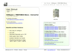
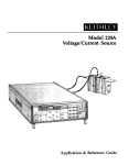
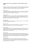
NCS-TT105 Temperature Transmitter User Manual Microcyber Inc. Contents 1. Brief Introduction .........................................................................1 2. Installation ...................................................................................2 2.1 Installation .............................................................................2 2.2 Wiring ....................................................................................3 3. Principle and Structure ................................................................6 4. FF Transmitter Configuration ....................................................10 4.1 Network Topology................................................................10 4.2 Function Blocks ................................................................... 11 4.3 Configuration .......................................................................12 4.4 Jumper-pin Configuration ....................................................20 5. PA Transmitter Configuration ....................................................21 5.1 Topologic Connection ..........................................................21 5.2 Function Block .....................................................................22 5.3 Function Configuration ........................................................23 5.4 Jump-pin Configuration .......................................................36 6. HART Transmitter Configuration ...............................................38 6.1Topologic Connection ...........................................................38 6.2 Function Configuration ........................................................39 6.3 Jump-pin Configuration .......................................................50 7. Adjusting in Workplace ..............................................................52 7.1 Operation Instruction for Magnetic Sticks ...........................52 7.2 Adjusting for FF Smart Transmitter .....................................54 7.3 Adjusting for PA Smart Transmitter .....................................60 7.4 Adjusting for HART Smart Transmitter ................................69 7.5 Return instrument data to factory data ................................80 8. Maintance..................................................................................82 9.Technical Specification ...............................................................84 9.1Basic Parameters .................................................................84 9.2 RTD Specification ................................................................84 9.3 TC Specification ..................................................................85 9.4 Physical Parameters ...........................................................86 Microcyber Inc 1. Brief Introduction NCS-TT105 smart temperature transmitter, using the fieldbus technology, is a new generation of smart fieldbus temperature transmitter and it is an indispensable field device for process control. NCS-TT105 transmitter integrates abundant function blocks and realizes not only general measurement function but also complicated control strategy. NCS-TT105 uses digital technology, so it can connect with many types of thermocouple and thermo resistive sensors. It has wide range and simple interface between field and control room, which reduces the expense of installation, operation and maintenance. NCS-TT105 supports HART, FF, and PA protocols. It can be widely used in the petroleum, chemicals, electricity, and metallurgical industries, etc. -1- Microcyber Inc 2. Installation 2.1 Installation For installation of NCS-TT105 temperature transmitter, three types of bracket (pipe mounting flat bracket, plate mounting angle bracket and pipe mounting angle bracket) are provided. Accordingly there are three installation methods as the following. The installation of pipe mounting flat bracket: the typical installation as Figure 2.1 shows. Fix NCS-TT105 temperature transmitter in flat bracket using four bolts provided, and then fix the flat bracket on the vertical pipe in Φ50mm around with the U-shape bolt provided. The installation of plate mounting angle bracket: the typical installation as Figure 2.2 shows. Fix NCS-TT105 temperature transmitter in angle bracket using four bolts provided, and then fix the angle bracket on the plate with the M10 bolt not provided. The installation of pipe mounting angle bracket: the typical installation as Figure 2.3, Figure 2.4 shows. NCS-TT105 temperature transmitter in angle bracket using four bolts provided, and then fix the angle bracket on the horizontal pipe in Φ50mm around with the U-shape bolt provided. -2- Microcyber Inc Figure 2.1 The installation of pipe mounting flat bracket Figure 2.2 The installation of plate mounting angle bracket Figure 2.3 The installation of pipe mounting angle bracket-1 Figure 2.4 The installation of pipe mounting angle bracket-2 2.2 Wiring The power and bus signal of NCS-TT105 temperature transmitter are sharing one pair of cables (bus cable). NCS-TT105 temperature transmitter is suggested to use specific Fieldbus cables recommended by the IEC61158-2. The wiring terminal is at the rear cover side, the wiring terminal -3- Microcyber Inc board could be seen when the rear cover is screwed off. FF+ FF- CH1CH2 COM CH3CH4 Figure 2.5 The wiring terminal board of NCS-TT105 temperature transmitter SENSOR1 CH1 CH2 SENSOR2 COM CH3 CH4 Figure 2.6 Wiring of NCS-TT105 temperature transmitter(3-wire) SENSOR1 CH1 CH2 SENSOR2 COM CH3 CH4 Figure 2.7 Wiring of NCS-TT105 temperature transmitter(2-wire) -4- Microcyber Inc SENSOR1 + SENSOR2 - CH1 CH2 - COM CH3 + CH4 Figure 2.8 Wiring of thermocouple Signal wire should be passed through the wire hole. Sensor signal wire shielding layer is single-point grounding. The bus signal wire shielding layer should be floating in instrument side, and be grounding in bus power side. The signal and bus cable should not share the line pipe or trunking with other equipment, and should be away from high-power device. -5- Microcyber Inc 3. Principle and Structure NCS-TT105 temperature transmitter uses resistive temperature detectors (RTD) or thermocouple and converts to fieldbus signal in order to measure temperature. NCS-TT105 temperature transmitter components, as shown in Figure 3.1. 1) 2) 3) 4) 5) consists of five Terminal board: it is used to connect with bus, temperature sensor, instrument board and communication board. Instrument board: it can convert the temperature sensor signal to voltage signal, and then provides the digital signal to board via A/D. Communication board: it is the core of smart instrument, providing the functions of fieldbus communication, control, diagnosis and maintenance. Isolation board: it is used for isolation between communication board and instrument board (including power isolation and signal isolation). Display board (optional): it is used to display temperature and function block parameters. -6- Microcyber Inc Round Board Isolation Board Terminal Board A/D Board Power Isolation BUS JTAG Interface Bus signal Power CH1 AMP EEPROM Power signal modulation Communication Controller Signal Isolation CPU FLASH RAM CH2 A/D CH3 AMP CH4 Display Part COM LCD Display Control Figure 3.1 Schematic diagram of NCS-TT105 temperature transmitter Size of NCS-TT105 Temperature transmitter Figure 3.2 Size of NCS-TT105 temperature transmitter (unit: mm) -7- Microcyber Inc Structure of NCS-TT105 temperature transmitter Figure 3.3 Structure of NCS-TT105 temperature transmitter 1 5 9 13 17 21 Front cover Positioning column Terminal board Name plate Terminal board Bottom cover 2 O-ring 3 6 Communication board 7 10 Screw 11 14 S/Z hole 15 18 Fixed column 19 -8- Display board housing Instrument board Wiring hole Electric housing Terminal cover 4 LCD board 8 Isolation board 12 Screw 16 Feedthru capacitor 20 Back cover Microcyber Inc As the core of NCS-TT105 temperature transmitter, the communication board connects terminal board, isolation board, instrument board and display board. The LCD board rotating in four angles is fixed on the communication board, as Figure 3.4 shows. 0% 50 % 0% PV 50% 100% PV 100 % Figure 3.4 Assembly structure of the transmitter -9- Microcyber Inc 4. FF Transmitter Configuration 4.1 Network Topology FF transmitter supports many kinds of connection, as shown in Figure 4.1. There is a transmitter bus connection; the bus ends are connect terminal matching resistance, which ensures the signal quality, as shown in Figure 4.2. The maximum length of bus is 1900 meters and it can be prolonged to 10 kilometers with repeaters. Primary Control Station Fieldbus I/O junction box FF bus Point to Point Bus Tree Figure 4.1 FF network topology - 10 - Microcyber Inc Up to 1900 meters FF Bus FF Bus Bus Power with Terminal Terminal Field FF device Link Master Figure 4.2 FF bus connection 4.2 Function Blocks FF smart transmitters carries out the FF standard function blocks, shown as the table below. Please refer to related FF protocol document for detailed info about configutaion methods of function blocks. Function Block Description Resource block is used to describe the device identity in the field, such as device name, RES manufacture, serial number. There is no input or output parameter in the resource block. Generally, there is only one resource block for each device. Transducer block is used to read sensor hardware TRD data, or write the data in the field to related hardware. Transducer block includes the info such - 11 - Microcyber Inc as range, sensor type, linearization, I/O data, etc. DSP DSP block is used to configure display info in LCD. PID function block has the function of PID control PID and setting point adjustment, process value(PV) filtering and alarm, output tracking, etc. Analog input function block is used to achieve AI transducer block input data and transfer to other function blocks, has the function of range conversion, square root, cut mantissa, etc. LLAG RA LLAG function block is used for feedforward control. RA function block is used to control the proportion between inputs. This block has a lot of features as set point PID Control treatment (value and rate limiting), filtering and alarm on PV, feed-forward, output tracking and others. This block has four analog inputs that may be selected IS by an input parameter or according to a criterion as first good, maximum, minimum, middle and average. This block has capability for two signal characteristics Signal based on the same curve. The second input has an option Characteristic for swapping “x” to “y”, and inverse function may be used in signal characteristic of read-back variables. 4.3 Configuration NCS-TT105 temperature transmitter can be configured by the Configurator software and NCS4000 DCS software of - 12 - Microcyber Inc Microcyber Inc, NI-FBUS Configurator of National Instrument, and DeltaV system of Rosemount. Environments 1) Windows 2000 or Windows XP system; 2) NCS-LD105 Linking Device, H1 Bus Power, H1 Terminator; 3) FF Configurator. Sensor type configuration Sensor type can be set by modifying SENSOR_TYPE parameter of transducer block, such as PT100, CU50. Figure 4.3 Sensor type configuration - 13 - Microcyber Inc Two-wire zero point calibration configuration For two-wire measurement, the two-wire zero point calibration can be set by modifying TWO_WIRES_COMPENSATION parameter of transducer block. Firstly, give zero point value to channel making a short circuit. Then set the TWO_WIRES_COMPENSATION parameter as “Start” to write in. If it is successful, read the parameter. If the parameter value is “Finished”, it indicates that two-wire zero point calibration is successful. Enable cold junction compensation If the sensor is thermocouple, the SECONDARY_VALUE is a cold junction temperature. In default status, first enable the cold junction compensation function. User is able to set cold junction compensation function by setting the SENCONDARY_VALUE_ENABLE. If it is set as Enable, it will be at enable cold junction compensation, the PRIMARY_VALUE is the temperature value after cold junction compensation. If it is set as Disable, it is at enable cold junction compensation forbidden; the PRIMARY_VALUE is the temperature value without cold junction compensation. Two-point linearization calibration Temperature transmitter has strict calibration in factory. Generally, it is not necessary for user to calibrate. User can use CAL_POINT_HI, CAL_POINT_LO and CAL_UNIT to carry out two-point linearization calibration. Operation steps shown as following: 1) Make sure and set SESOR_TYPE, and set CAL_UNIT - 14 - Microcyber Inc according to sensor type. Now it supports Celsius, Ohms and MV. 2) Set transducer block MODE parameter as “OOS”, and then set the SENSOR_CAL_METHOD as “User Trim Standard Calibration”. 3) Give standard data to channel to calibrate via standard source, when the input is stable, write calibration data to CAL_POINT_HI or CAL_POINT_LO according to upper limit calibration or lower limit calibration. It is successful if there is no write error. Notes: The calibration will be fail if there is a great deviation between write-in calibration data and practical input channel data. Multi-point linearization calibration User can carry out the second calibration for transmitters via calibration parameters CAL_CURVE_X and CAL_CURVE_Y of transducer blocks: 1) Smart temperature transmitter supports 8 calibration point inputs—the parameter CAL_CURVE_Y array of the transducer block. User can write output value to calibrate into array in turn and select unit. For example, when for three-point interpolating calibration, 10, 20, 30 can be selected as the calibration points, the values are written in CAL_CURVE_Y array, shown as Figure 4.4. - 15 - Microcyber Inc Figure 4.4 CAL_CURVE_Y configuration 2) Input standard signal via standard source, open the related transducer block, read the PRIMARY_VALUE value and write it to the CAL_POINT_X array. For example, if the read value is 10.2, 20.5, 30.4, are written to the CAL_POINT_X array, shown as Figure 4.5. The calibration is finished. - 16 - Microcyber Inc Figure 4.5 CAL_POINT_X configuration Set SENSOR_CAL_METHOD as “User Trim special Calibration” and set ENABLE_LIN_CURVE as “Enable Curve”, which makes the smart transmitter work according to calibrated characteristic curve. LCD Configuration In default status, the LCD of smart temperature transmitter displays PRIMARY_VALUE of the first channel transducer block,shown as Figure 4.6. If you need to display parameter info of other function blocks, you may configure as following steps: (X represents 1, 2, 3 and 4. There are 4 groups of parameters; each group can be configured separately. Smart temperature transmitter can display different parameters in cycle. ) If parameter configuration is wrong, it will display 3) - 17 - Microcyber Inc CONFIG_ERR. You should write display block mode as OOS before the correct configuration, and write as AUTO when it is configured successfully. Thus the configuration is effective. 1) BLOCK_TAG_X: The parameter defines the name of function block to display. For example, if you would like to display some parameter in AI1 function block, you should configure BLOCK_TAG_X and define the parameter as “AI1”. Notes: It is required that the input character must be 32 bytes, if it is less than 32 bytes, you should use blank to fill in, otherwise it won’t display correctly. For example, if you would like to input “AI1”, you should write “AI1” in configuration software. 2) RELATIVE_INDEX_X: The parameter defines the parameter index of display function blocks. For example, if you would like to display AI1 output value, you should define the parameter as 8(8 is AI1 function block OUT parameter index). User should refer to FF function block protocol for more info about function block output parameter index. 3) SUB_INDEX: The parameter defines the parameter sub-index of display function blocks (if there is). For example, if you would like to display OUT parameter value in AI1 function block, you should define RELATIVE_INDEX_X as 8, and define SUB_INDEX_X as 2(2 is the sub-index in OUT parameter value). 4) MNEMONIC_X: The parameter is the name of display - 18 - Microcyber Inc 5) 6) parameter, and it can be input at random. The number of character is no more than 16. DECI_PNT_NUMB_X: The parameter defines the precision of display parameter. For example, if you would like to display 3 bits after the decimal point, it should be defined as 3. ACTIVE_X: The parameter value is FALSE or TRUE. When other parameters are configured ready, you should write it as TRUE so that it can activate the configured parameters, and later, the related parameter info will be shown in the LCD of smart temperature transmitter. Figure 4.6 Parameter configuration for display block - 19 - Microcyber Inc 4.4 Jumper-pin Configuration SIM WP RST NCS-TT105 temperature transmitter has three hardware jumpers, shown as Figure 4.7. SIM Jumper: Simulattion jumper can achieve simulation function. WP Jumper: Write protection jumper can refuse any write operation for FF smart transmitter, which can avoid the vicious modification for instrument data. RST Jumper: Reset jumper will reset the transmitter data back to factory. Please make the transmitter powered off, insert the jumper to RST, and then power the transmitter on, the data will be back to factory data. Figure 4.7 NCS-TT105 temperature transmitter hardware jumpers - 20 - Microcyber Inc 5. PA Transmitter Configuration 5.1 Topologic Connection PA transmitter supports many kinds of connection, as shown in Figure 4.1. There is a transmitter bus connection; the bus ends are connect terminal matching resistance, which ensures the signal quality, as shown in Figure 4.2. The maximum length of bus is 1900 meters and it can be prolonged to 10 kilometers with repeaters. PROFIBUS DP BUS Coupler Box PROFIBUS PA BUS Point-to-Point Bus with distributed wires Tree Figure 5.1 PRFIBUS PA network topology - 21 - Microcyber Inc Maxim 1,900m PA Bus PA Bus Terminator Terminator Fieldbus Power Supply Field PA Device Coupler Figure 5.2 PRFIBUS PA bus commection 5.2 Function Block PA smart transmitter carries out the PA standard function blocks, shown as the table below. Please refer to related PA protocol document for detailed info about configutaion methods of function blocks. Function Block Description Physical block information, Physical Block describes recognizing device and hardware diagnosing information, including device number, software version, hardware version and installation dates, etc. Transducer block separates function blocks from Transducer Block the instrument input and output characteristic, it mainly carries out the function such as calibration and linearization for input and output data, and then - 22 - Microcyber Inc provides the processed data to AI through the inner channel. AI block gets simulation processing value from the Analog Block Input inner channel, and then processes the value, providing proper measurement value to master station via bus communication. 5.3 Function Configuration PA smart transmitter parameter configuration keeps to Profibus PA Specification Version 3.01. It can carry out read and write function for transmitter function block parameters with Simatic PDM, also is able to configure transmitter with Siemens Step7. Configuration Environment: 1) PC, Windows 2000 or Windows XP 2)Siemens Step7 configuration software, PDM device management software 3) DP/PA coupler or linker 4) 1st master station: e.g. PLC; 2nd master station: e.g. CP5611 board 5) PA terminator matcher 6) Standard temperature source Temperature transducer block parameter configuration: Transducer block separates function block from sensors, actuators and other I/O devices. It depends on the device supplier to access and control I/O devices. Transducer block is able to get input data and set output data by accessing I/O devices. Generally, transducer block has the function of - 23 - Microcyber Inc linearization, specialization, temperature compensation and data’s control and exchange, etc. Transducer block structure is shown as figure 5.3. Process Transducer Block Transducer Block RJ_TEMP 1 R.J. 0 2 AI FB(’s) EXTERNAL_RJ_VALUE RJ_TYPE R.J. Comp. T1 Input 1 T2 Input 2 Arithmetic LIN Input Linearization + BIAS_1 LIN + LIN + SECONDARY_VALUE_1 PRIMARY_VALUE + BIAS_2 LIN_TYPE, TAB_... INPUT_RANGE, SENSOR_CONNECTION, COMP_WIRE1/2 SECONDARY_VALUE_2 SENSOR_MEAS_TYPE Figure 5.3 Transducer block structure Parameters of transducer block are as follows: Parameter INPUT_FAULT_GEN Function Description Input fault: includes the failure diagnosed objects of all values. 0: Device normal Bit 0: Rj Failure Bit 1: Hardware failure Bit 2-4: Reservation Bit 5: Manufacture designation Bit 6: Communication failure Bit 7: Manufacture designation - 24 - Microcyber Inc INPUT_FAULT_1 Input fault: the failure diagnosed objects related to SV_1 0: Input normal Bit 0: Reservation Bit 1: Higher than the upper range Bit 2: Break Bit 3-5: Reservation Bit 6: Communication failure INPUT_FAULT_2 Input fault: the failure diagnosed objects related to SV_2 Please refer to INPUT_FAULT_1 for the bit description. BIAS_1 Deviation value for processing parameters of Channel 1 Units are set by PRIMARY_VALUE_UNIT. BIAS_2 Deviation value for processing parameters of Channel 2 States are set by PRIMARY_VALUE_UNIT. INPUT_RANGE 0: mV Range 1 => mV 100 128: Ω Range 1 => Ohm 500 129: Ω Range 2 => Ohm 2000 LIN_TYPE Linearization type Sensor mathematics function type, coding as follows: 0: PV = SV_1 1: PV = SV_2 SENSOR_MEAS_TYP 128: PV = SV_1 - SV_2 D-value E 129: PV = SV_2 - SV_1 D-value 192: PV = ½ * (SV_1 + SV_2) Average Value 194-219: Reservation 220-239: Manufacture designation - 25 - Microcyber Inc PRIMARY_VALUE Transmitter measurement value and status Units are set by PRIMARY_VALUE_UNIT. PRIMARY_VALUE_U NIT Engineering unit measurement value UPPER_SENSOR_LI MIT Sensor physical upper limit LOWER_SENSOR_L IMIT Sensor physical lower limit SECONDARY_VALU E_1 (SV_1) From Channel 1 and the processed value and status calibrated by BIAS_1. Units are set by PRIMARY_VALUE_UNIT. SECONDARY_VALU E_2 (SV_2) From Channel 2 and the processed value and status calibrated by BIAS_2. Units are set by PRIMARY_VALUE_UNIT. MAX_SENSOR_VAL UE_1 SV_1 Maxim。State Definition according to SECONDARY_VALUE_1。 MIN_SENSOR_VAL UE_1 SV_1 Minim 。 State Definition according to SECONDARY_VALUE_1。 MAX_SENSOR_VAL UE_2 SV_2 Maxim。State Definition according to SECONDARY_VALUE_2。 MIN_SENSOR_VAL UE_2 SV_2 Minim 。 State Definition according to SECONDARY_VALUE_2。 code of transmitter Thermocouple additional parameters as follows: Parameter EXTERNAL_RJ_VALU E Function Description Fixed value from outer reference point. Unit is set by PRIMARY_VALUE_UNIT. If the unit is not for temperature, it should be set as ℃. - 26 - Microcyber Inc RJ_TEMP Temperature at reference point. Unit is set by PRIMARY_VALUE_UNIT. If the unit is not for temperature, it should be set as ℃. RJ_TYPE Setting reference point type, coding as follows: 0: No reference, no compensation. 1: Inner, temperature at reference point self-tested by the device. Choose 1 when in default. Thermo resistance additional parameters as follows: Parameter Function Description COMP_WIRE1 Linearization compensation for thermo resistance 1 selecting 2-wire or 3-wire. Unit is fixed as Ω. COMP_WIRE2 Linearization compensation for thermo resistance 2 selecting 2-wire or 3-wire. Unit is fixed as Ω. SENSOR_CONNECTIO N It can be used to connect sensor with 2-wire or 3-wire. 0: 2-wire 1: 3-wire Parameters defined by manufacture: Parameters Function Description SENSOR_VALUE_1 Original data value for sensor 1. SENSOR_VALUE_2 Original data value for sensor 2. CAL_POINT_HI Calibration value at the highest point The unit is set by CAL_UNIT. CAL_POINT_LO Calibration value at the lowest point - 27 - Microcyber Inc The unit is set by CAL_UNIT. CAL_MIN_SPAN Allowable minimum step length during the calibration ensures the calibration smoothly, and the distance between highest point and lowest point is not too close. The unit is set by CAL_UNIT. CAL_UNIT Calibration units (℃, Ω, mV) CAL_CHANNEL Select calibration channel: 0:CHANNEL1; 1:CHANNEL2. TWO_WIRES_COMPEN SATION 2-wire zero point compensation PROFIBUS periodic data communication configuration PROFIBUS DP periodic data communication is to exchange input output data, between 1st Class master station and slave station, in the polling way. The communication method is non-connected. In every cycling period, 1st Class master station sends data exchange request, the slave station answers it passively. The periodic data communication is mainly applied in configuration between slave station and PLC master station. With it, master station PLC receives slave station input data or output the data to slave station. PA smart transmitter periodic data communication configuration is similar to PROFIBUS DP slave station, only a coupler or a linker between PA BUS and DP BUS is needed to add between PA bus and DP bus. PA smart transmitter periodic data comes from output - 28 - Microcyber Inc parameters of AI function block. There are 5 bytes, including 4 bytes of temperature floating data and a byte status byte. As for periodic communication, 2 identifiers are supported by transmitter, those are, short identifier 0x94 and long identifier 0x42, 0x84, 0x08, 0x05. You may use Siemens Step7 to configure periodic data communication for PROFIBUS PA. Following is an example for configuration with Siemens Step 7: Turn on SIMATIC Manager, select PLC master station and create a new project, shown as figure 5.4. Figure 5.4 Select PLC master station and create a new project Click Hardware twice to turn on HW Config Software Hardware Configuration. Select Install GSD to install PA transmitter GSD document in Option list, shown as figure 5.5. - 29 - Microcyber Inc Figure 5.5 Install GSD After GSD Document is installed successfully, the installed PA device will be listed in the PROFIBUS-PA index on the right of HW Config Software. Click it and drag it to the PROFIBUS DP bus, shown as figure 5.6. Figure 5.6 Drag it to the PROFIBUS DP bus - 30 - Microcyber Inc Download the configuration information to PLC master station in the PLC list. Then the periodic data communication configuration between PA instrument and master station is finished, shown as figure 5.7. Figure 5.7 Download the info to PLC PROFIBUS non-periodic data communication configuration PROFIBUS DP non-periodic data communication is the data communication between 2nd Class master station and slave station, facing connection. The data communication is non-periodic, without affecting data communication. The non-periodic data is mainly PA function block parameters, together with recognizing and diagnosing information for the device. The non-periodic data communication is mainly applied in management, recognizing, diagnosing, testing, maintaining for PA device. Siemens device management software SIMATIC PDM can be used to carry out the non-periodic data configuration for PA - 31 - Microcyber Inc instrument. There is an example given below to show non-periodic data configuration for PA instrument. Open the LifeList software attached by SIMATIC PDM, select Start to scan DP bus in Scan list, shown as figure 5.8. Figure 5.8 Start LifeList After scanning the bus, slave station device in DP bus will be listed, meanwhile the device manufacture ID number and some diagnosing information are displayed, shown as figure 5.9. Figure 5.9 Scan DP bus and List PA device - 32 - Microcyber Inc Click PA device twice to start SIMATIC PDM software. You may read, write and diagnose parameter for PA device. Select the Device catalog... when you are asked to select the PA instrument type, lead the GSD document. Microcyber Inc\NCS-TT105 can be selected for the NCS-TT105 series of PA transmitters, shown as figure 5.10. Figure 5.10 Select Device Type After selecting the device type, click OK, thus non-periodic data communication is configuration successfully. You can carry out the parameter read and write via the function of upload and download function of PDM Software, shown as figure 5.11. - 33 - Microcyber Inc Figure 5.11 Device Management with PDM software Online, offline configuration function PA smart transmitter realizes PA standard function blocks, online and offline configuration functions realize function block parameters configuration separately. With PDM software, after configuration, choose Device -> Online Configuration or Device -> Offline Configuration, to do write operation for the function parameter. Sensor type configuration Sensor Type can be set by modifying Characterization Type and Input Range and Mode Parameters of transducer block. E.g. PT100, CU50, etc. When Characterization Type Parameter is Linear, Input Range and Mode Parameters are effective. 2-wire zero point calibration configuration For 2-wire measurement, you - 34 - may use Microcyber Inc TWO_WIRES_COMPENSION parameter to calibrate. First, set zero value for channel, which will cut the channel off. Next, turn on PDM software, after the configuration, choose Device -> Offline Configuration -> Transducer Block 1. In Advanced Settings, there is 2-wire calibration function. After pressing write button, when Finished is displayed, it means 2-wire zero point calibration is successful. Enable cold-end temperature compensation When thermocouple is used as sensor, Reference Junction Temperature parameter of transducer block is cold-end temperature value. Primary Value is measurement value related to cold-end temperature value. If 0℃ is to display in primary value output, it can be realized by setting Reference Junction parameter. If 1℃ is to display in primary value output, it can be realized by measurement temperature as well as cold-end temperature as Primary Value output. The cold-end temperature compensation is enabled in default. 2-point linearity calibration Strict calibration must be done to temperature transmitter in the factory, so it is not necessary for users to calibrate again. The parameters such as Lower Calibration Point, Upper Calibration Point and Calibration Unit areused to carry out 2-point linearity calibration. Operation Steps: 1) Turn on PDF software, after configuration; choose Device -> - 35 - Microcyber Inc Calibration -> Lower/Upper, get page of temperature calibration. 2) Make sure of sensor type, set Characterization Type and Input Range and Mode, and set Calibration Unit according to sensor type. It supports the parameters ℃, Ω, and mV. Write the parameter after the setting. 3) Give standard data to channel to calibrate. When the input is stable, write calibration data to Upper Calibration Point or Lower Calibration Point according to the operation one is upper calibration or lower calibration. If there is no write error, the calibration is successful. Notes: There should not be a great deviation between written calibration data and practical input channel data, otherwise the calibration will be in failure. Notes: When you are using Device -> Master Reset, it may course the instrument CPU reset as well as communication broken, which is normal. Please connect again. 5.4 Jump-pin Configuration PA smart temperature transmitter has three hardware jumpers, by now, only two of them are used, SIM Jumper isn’t, shown as figure 5.12. - 36 - SIM WP RST Microcyber Inc Figure 5.12 PA Smart Transmitters Hardware Jumper RST Jumper: Reset jumper will reset the transmitter data back to factory. Please make the transmitter powered off, insert the jumper to RST, and then power the transmitter on, the data will be back to factory data. Attention: When the instrument is back to factory data, please turn off the power supply again, extract the jumper in RST, and then use the instrument as usual. If there is jumper in RST, when you restart the instrument next time, all the data will be back to factory data and configuration info before power-off will be missing. WP Jumper: Write protection jumper can refuse any write operation for PA smart transmitter, which can avoid the vicious modification for instrument data. - 37 - Microcyber Inc 6. HART Transmitter Configuration 6.1Topologic Connection The connection of HART smart transmitter includes 4~20mA compatible mode and networking mode. 4~20mA compatible mode Figure 6.1 4~20mA compatible mode Feature: 1) Connected to the above control system above via AI module and HART communication device 2) Mixed use of the analog and digital communication 3) The device address is 0. - 38 - Microcyber Inc Networking mode Figure 6.2 Networking mode Feature: 1) Connected to the above control system via HART communication device 2) Only use digital function of HART device, and the fixed current on wire is 4mA; 3) Support 15 devices in the mode of short address. 6.2 Function Configuration Smart transmitter can be configured by the HART configuration software, which includes functions: 1) Basic information configuration: configure the basic information of device online, including tag, address, date, assemble number and so on. 2) Configurable information configuration: configure the configurable information of device online, including - 39 - Microcyber Inc primary variable range, damp and so on 3) Sensor info configuration: configure the sensor info of the online device, including type, wiring, etc. 4) Current calibration: Can calibrate 4~20mA current of online device, also can set fixed current output. 5) Variable monitoring: refresh all dynamic variable of selected online device timely and display trend curve of present device primary value. 6) Special commands: carry out special commands provided by HART transmitter. Configuration setting 1) PC with serial, the OS is Windows 2000 or Windows XP 2) HART Modem and serial wire 3) Matching resistance 250~550 ohm Basic information configuration Through the dialog of basic information, the basic information of the smart transmitter can be read or modified, including device address, message, description, date, assemble number, alarm, write protection, manufacturer ID, device type, device ID, long address and version info, shown as Figure 6.3. After information modification, click the “Apply” button to download it into device. 1) The address selection range is 0~15 2) Message can be input 32 characters at most 3) The maximum length of the description is 16 characters - 40 - Microcyber Inc 4) The maximum length of the tag is 8 characters 5) Date range is from the year 1900 to 2155. 6) Assemble number is 6 characters at most. Figure 6.3 Dialog of basic information Configurable information configuration Through the dialog of configuration information, the configuration information of smart transmitter can be read or modified, including display device output variable (primary variable, second variable, current value and percentage), primary variable info setting (output type, damp value, unit, upper limit and lower limit) and range calibration, etc. ,shown as Figure 6.4. - 41 - Microcyber Inc 1) Output variable Output Description variable Primary value can be signals of temperature, PV value resistance and mV. Cold-end Second temp. temperature. Current Display PV corresponding to current value at value 4~20mA Percentage Display variable PV is set as corresponding cold-end to present percentage of the range 2) Primary variable setting PV type: setting PV output mode, shown as following. PV type Description st SENSOR_1 PV is from the 1 sensor SENSOR_2 PV is from the 2 SENSOR_1 - SENSOR_2 SENSOR_2 - SENSOR_1 MAXIMUM MINIMUM AVERAGE nd sensor PV is D-value PV is D-value PV is the maximum value between the two sensors. PV is the minimum value between the two sensors. PV is the average value between the two sensors. Damp: range 0~32s Unit: PV unit modification affects variables related to unit, such as the upper or lower limit for the range or for the sensor. When - 42 - Microcyber Inc you modify the unit, you can’t modify upper or lower limit for the primary variable range, instead, you should modify them separately. The unit can be set as: ゜C,゜F,゜R, K, mV, Ohm. Upper limit of the range: output current PV related to 20mA. Lower limit of the range: output current PV related to 4mA. You should press “Apply” to download it into device after the modification. Set “upper limit of range” with present value: Set the PV as the upper limit of primary variable range, and keep the lower limit of range the same. Set “lower limit of range” with present value: Set the PV as the lower limit of primary variable range, and keep the upper limit of range the same. Set “primary variable zero point” with present value: Set the PV as the primary variable zero point when the temperature is 0゜C. 3) Transmitter calibration Calibrate the lower limit of range:Make the measurement primary variable value as the lower limit of range, and the range should be not changed (the upper limit of range is modified accordingly). If the adjustment of the upper limit of range exceeds the upper limit of sensor range, make the upper limit of sensor as the adjusted upper limit of range, and then the range is changed sequencely. Calibrate the upper limit of range:Make the measurement primary variable value as the upper limit of range, and the lower - 43 - Microcyber Inc limit of range should not be changed, so the range is changed. If the adjustment of the upper limit of range exceeds the upper limit of sensor range, make the upper limit of sensor as the adjusted upper limit of range. Calibrate the zero of the primary variable:Calibrate the zero displacement of primary variable due to installation location. Figure 6.4 Configuration Information 4) Sensor configuration You may check the current configuration sensor info (upper limit, lower limit and minimum span) via sensor info TAB. Also, you may configure the sensor type and wiring with it. HART smart temperature transmitter supports 2 temperature sensors, shown as Figure 6.5. Sensor Type: sensor type supported by device, shown as following: Sensor Type Description SCALE_0_500R Resistance, 0 ~ 500Ω SCALE_0_4000R Resistance, 0 ~ 4000Ω - 44 - Microcyber Inc SCALE_CU50 Cu50 RTD SCALE_CU100 Cu100 RTD SCALE_PT100 PT100 RTD SCALE_PT1000 PT1000 RTD SCALE_100MV MV voltage signal, range from -100 to +100 mV SCALE_B_TC B type thermocouple SCALE_E_TC E type thermocouple SCALE_J_TC J type thermocouple SCALE_K_TC K type thermocouple SCALE_N_TC N type thermocouple SCALE_R_TC R type thermocouple SCALE_S_TC S type thermocouple SCALE_T_TC T type thermocouple Wiring: It can be set as 2-wire or 3-wire, only effective to RTD. Cold-end Compensation: It enables or disables thermocouple’s cold-end compensation function. 2-wire zero point calibration: When the temperature transmitter is connected to RTD in 2-wire way, in order to avoid the resistance error in the cable, you should short-circuit the sensor and execute zero point calibration button. Once calibration: Factory calibration for sorts of resistance ranges. (only for manufacture) R0 correction factor: correct the error of sensor itself. - 45 - Microcyber Inc Figure 6.5 Sensor configuration 5) Current Calibration You may use current calibration TAB to calibrate online device 4~20mA current and configure fixed current output. The steps of current calibration are shown as following: (1) Connect the loop, an ammeter with the 5 1/2 digit precision should be series-wounded in the output loop of the smart transmitter. (2) Set device rolling address as 0, please refer to basic info configuration. If rolling address is 0 already, this step can be skipped. (3) Enter current calibration option TAB. (4) Select “current value” as 4mA, when the ammeter is stable, input the value in ammeter to “adjustment value”, and then click “Apply”. (5) Select “current value” as 20mA, when the ammeter is stable, input the value in ammeter to “adjustment value”, and then - 46 - Microcyber Inc click “Apply”. (6) Select “current value” as blank, make the device output current as PV value. Configure Current Fixed Output Input the value of the current the smart transmitter will be fixed on, to “fixed current value”, and click the button “enter/exit fixed current mode” to enter or exit the mode of fixed current output. The text of the button can display “exit fixed current mode” and “enter fixed current mode” in turn, to tell users what to do. In the run of the HART smart transmitter, compare the value of the primary variable and range upper/lower limit of the of the primary variable continuously. When the value of the primary variable exceeds the range of the primary variable, the smart transmitter will output fixed current to indicate that the value of the primary variable is exceeded. When it is over the upper limit, the smart transmitter output fixed current 20.8mA;When it is less than the lower limit, output is 3.9mA. Figure 6.6 Current configuration - 47 - Microcyber Inc Note: Calibration current and fixed current output functions are only in the moment when the polling address is 0. It will be at absolute digital communication mode at other polling addresses, the failure info is “Command Execution Failure”. 6) Variable Monitoring The user is able to refresh all the dynamic variables of the selected device and display trend curve of present device primary variable via variable monitoring tab. The present refreshing variables are: PV value, current value, percentage and SV value. Figure 6.7 Variable monitoring 7) Special Command The user is able to carry out all the special functions of HART smart transmitter via special command tab, shown as Figure 6.8. Configure LCD Display Type The function is used to set the content of LCD. There are 5 - 48 - Microcyber Inc options: PV value, SV value, current value, percentage and circulated display PV value current value. Small Signal Cut The function is used to set small signal cut variable, the variable is the proportion in the full range. The setting value range: more than 0, and less than 0.005. Shown as the figure, if the setting value is 0.002, the value in ± 0.002 of full range can be ignored. If the sensor type is 0-4000R, the value in ±8 ohm can be ignored, the PV value output is 0 ohm. Recover Leave Factory Default Value Click this button, all the data will be recovered to leave factory status. If the user saved the leave factory value, all the data will be back to saved status. If not, the data will be back to leave factory default status. Save As Leave Factory Value Click this button, all the data will be saved as leave factory value. Click the button of leave factory default value, it will recover the saved configuration. Range Calibration Recovery Click this button, range calibration will be back to original status. Primary Variable Zero Point Recovery Click this button, primary variable zero point will be back to original status. - 49 - Microcyber Inc Figure 6.8 Special Command 6.3 Jump-pin Configuration HART smart transmitter has two hardware jumpers, shown as Figure 6.5. The three points on bottom are failure alarm current setting jumpers, and the top three points are calibration protection setting jumpers. Failure Alarm Current Jumper HART smart transmitter has self-diagnosis function. When a failure is tested out, the transmitter will output alarm current automatically. The alarm current mode depends on failure alarm current jumper setting on the right side of the communication board. When the jumpers are in the two points marked with “Hi”, it will be the high level alarm (≧21.75mA). When the jumpers are in the two points marked with “Lo”, it will be the low level alarm (≦3.75mA). Calibration Protection Setting Jumper HART smart transmitter supplies the calibration protection jumper setting or not, shown as Figure 6-5. When the jumper is - 50 - Microcyber Inc at the right side of two points marked with “WRD”, it will be the calibration protection. And at that time, the HART smart transmitter does not allow any operation about modifying device configuration. When the jumper is at the right side, the HART smart transmitter allows the operation about modifying device configuration. Figure 6.5 HART smart transmitter hardware jumper - 51 - Microcyber Inc 7. Adjusting in Workplace 7.1 Operation Instruction for Magnetic Sticks The adjusting in workplace can be realized by inserting magnetic sticks into the holes named as “SPAN” or “ZERO”, which are on the top of the transmitter housing, shown as figure 7.1. Figure 7.1 Location of magnetic sticks inserted holes and full.scale LCD The following will show how to utilize different combinations of magnetic sticks inserting to simulate four virtual key buttons, which is for description of adjusting in workplace. According to different functions, the four virtual key buttons are defined as Mode (M), Input adjusting ([↑], [↓]) and Confirmation ([Enter]). Mode (M): It can be switched in all operational modes. Input adjusting [↑]: Increment operation. Input adjusting [↓]: Degression operation Confirmation [Enter]: Confirmation operation. The detailed info for operations of (M), [↑], [↓] and [Enter] are shown as following: - 52 - Microcyber Inc (1) Mode Input adjusting [M] [↓] (1) [↑] Confirmation [Enter] ) Insert the magnetic sticks into “Zero” and “Span” at the same time Insert “Zero” and Zero Span “Span” for 2s, get them out (1) (2) Notes: 1) Insert / Get out the magnetic sticks in Mode (M) and Input adjusting is considered as ([↑], [↓]) button operation once, also, inserting the magnetic sticks for long can be considered as long operation. In a button operation, it is suggested that user should insert the magnetic sticks for 1s, and then get it out. Otherwise, the operation can’t be tested. The long operation is carried out automatically every two seconds. 2) In order to avoid the collision between Confirmation and Mode, when user is carrying out the confirmation operation, when the process is 100%, it means that the magnetic sticks are inserted for 2s, and then get the two magnetic sticks out to make sure the confirmation operation. When the process is 100%, the magnetic sticks are not gotten within 3s, which means to carry out switch operation. When the process is not 100%, user shall get the magnetic sticks out without operation. 7.1.1 General Adjusting Method Following is the general adjusting method. Please refer to - 53 - Microcyber Inc specific description for info in detail. In the measurement value display mode, press Mode [M] to do mode switch. When it is displayed in mode needs to be adjusted, get out the two magnetic sticks, the present value to be adjusted will be displayed in the LCD. Press [↑] or [↓] to adjust, after that, press [Enter] to confirm. Press [M], switch to measurement value display mode. Notes: 1. It is not necessary to confirm for some functions. After adjustment, it is saved at the same time. 2. If there is no button operation within 1 min (There is no magnetic sticks inserted in the two holes), it will return to normal display mode. 3. Carrying out the calibration function, after the successful calibration, it will be back immediately to LCD display mode. 7.2 Adjusting for FF Smart Transmitter In this section, we describe the adjusting steps of FF smart transmitter. By adjusting in the workplace, you can carry out upper limit calibration, lower limit calibration, setting sensor type, wiring and so on for transmitters. The functions and operation are shown as following in detail. Mod Function Button Function e [M] [↑] [↓] [Enter] Functio Display, n description Display [M] Display the configuration info Measure ment - 54 - Microcyber Inc Mod Function e [M] value display Failure display No. Channel Lower limit Upper limit Sensor Type Sensor Wiring Button Function 02 16 17 22 23 [↑] [↓] [Enter] Functio Display, n description Display [M] displayed by DSP display block Failure! When the transmitter is in failure, it will display the reason. Pre-calibratio Ascendin Fun02 n Decreasing g CH_x No.Channel x:1 or 2 Pre-settin Set the lower Fun16 Pre-setting g Implementatio limit of LOWE n characteristic decreasing ascendin R g curve Pre-settin Set the upper Pre-setting g Implementatio Fun17 limit of n UPPER characteristic decreasing ascendin g curve Thermocoupl Pre-settin e, thermo Pre-setting g Implementatio Fun22 resistance, n S_TYP decreasing ascendin voltage, g resistance Pre-settin Pre-setting g Implementatio Fun23 2-wiring, ascendin n CONN 3-wiring decreasing g - 55 - Microcyber Inc Press [M], it can be switched among the functions above. Measurement Value Display(NORM) Upper Limit (UPPER) [M] [M] No. Channel (CH_1 or CH_2) Sensor Type (S_TYP) [M] [M] Lower Limit (LOWER) Sensor Wiring (CONN) [M] [M] Figure 7.2 Adjusting function and LCD display In mode switch, the Number Display will display function code, e.g. “Fun02” and the Text Display will display function description shown as above, e.g. “CH_1”. In addition, there is no need to confirm Mode 02, it will be saved after the adjusting. 7.2.1 Measurement value display It will display configuration info of DSP display block, and the local operation can’t modify the unit. When the value exceeds the LCD range, it will display in scientific notation. The method to return measurement value: (1) Switch mode to “NORM”. (2) There is no operation within 1 min. (There are no magnetic sticks for the 2 holes) - 56 - Microcyber Inc 7.2.2 Error Display In the course of local operation, the following error info may occur: Display NumEr FNErr Lock Explanation Number Error Mode Number Error The jump-pin is set as configuration protection. 7.2.3 Pre-setting No. Channel—Mode 02 It is used to set No. Channel, the default is CH_1. The range of No. Channel: CH_1- CH_2. You may set No. Channel according to following steps: --Select mode 02, the present No. Channel will be displayed in text display. --Use [M] to do mode switch. The No. Channel affects functions such as sensor type, sensor wiring, etc. Please set the No. Channel before doing pre-adjusting. 7.2.4 Operation steps for lower limit of range—Mode 16 In this mode, you shall modify the slope of characteristic curve. The characteristic curve is rolling around the high setting point. You shall implement the calibration of lower limit according to the following steps: - 57 - Microcyber Inc --Select mode 16, LCD will display the calibrated process value last time and related unit, --Input the reference temperature value starting from this point via [↑] or [↓], --Press [Enter] to set. If the setting is successful, it will show “OK”, otherwise, it will show “Err”, --Use [M] to do mode switch. Please refer to 7.1 for detailed info about processing bar. 7.2.5 Operation steps for upper limit of range—Mode 17 In this mode, you shall modify the slope of characteristic curve. The characteristic curve is rolling around the low setting point. You shall implement the calibration of upper limit according to the following steps: --Select mode 17, LCD will display the calibrated process value last time and related unit, --Input the reference temperature value starting from this point via [↑] or [↓], --Press [Enter] to set. If the setting is successful, it will show “OK”, otherwise, it will show “Err”, --Use [M] to do mode switch. Please refer to 7.1 for detailed info about processing bar. - 58 - Microcyber Inc 7.2.6 Operation steps for setting sensor type—Mode 22 It is about setting sensor type. Before setting the type, you should set No. Channel for the pre-modified type via Mode 02. FF smart transmitters support 15 sensor types. You shall set sensor type according to the following steps: --Select mode 22, LCD will display sensor type identifier and related type identification, --Select sensor type via [↑] or [↓], --Press [Enter] to set. If the setting is successful, it will show “OK”, otherwise, it will show “Err”, Please refer to 7.1 for detailed info about processing bar. 15 sensor types supported by FF smart transmitters are shown as following: Identifier 1 2 3 4 5 6 7 8 Type Description 500R 4000R CU50 CU100 PT100 PT1K 100MV B_TC Identifier 9 10 11 12 13 14 15 Type Description E_TC J_TC K_TC N_TC R_TC S_TC T_TC 7.2.7 Operation steps for setting sensor wiring—Mode 23 It is about setting sensor wiring. Before setting the wiring, you should set No. Channel for the pre-modified type via Mode 02. FF smart transmitters support 2-wiring and 3-wiring. - 59 - Microcyber Inc You shall set sensor wiring according to the following steps: --Select mode 23, LCD will display sensor wiring value, --Select sensor wiring via [↑] or [↓], --Press [Enter] to set. If the setting is successful, it will show “OK”, otherwise, it will show “Err”, Please refer to 7.1 for detailed info about processing bar. 7.3 Adjusting for PA Smart Transmitter In this section, we describe the adjusting steps of PA smart transmitter. By adjusting in the workplace, you can carry out bus address, physical unit, sensor type, sensor wiring and so on for transmitters. The functions and operation are shown as following in detail. Function Mod e [M] Button Function [↓] [↑] [Enter] Measureme Functi on Displa y Description displayed in Mode 11 nt Value Display Failure display No. Channel 02 Decreasi Ascendi ng ng 11 Select 1 from 5 possibilities Measureme nt Value Failure! When the transmitter is in failure, it will display the reason. Display Fun02 No. Channel x:1 CH_x or 2 Fun11 PV、SV1、SV2、 DISP AI、RJTEMP Display - 60 - Microcyber Inc Function Mod e [M] Button Function [↓] [↑] [Enter] Functi on Displa y Description Fun12 UNIT Temperature unit, mV,ohm Type Primary Variable Unit 12 Select Pre-setti Pre-setti Bus Address 13 ng ng Implementati Fun13 decreasi ascendin ng on ADDR g Fun14 DECP T User address in PROFIBUS(0…1 26) Decimal Point 14 Sensor Type Thermocouple, Pre-setti Pre-setti thermo ng Implementati Fun22 ng 22 resistance, on S_TYP decreasi ascendin voltage, g ng resistance Sensor Wiring Pre-setti Pre-setti ng Implementati Fun23 ng 23 2-wiring, 3-wiring ascendin on CONN decreasi g ng Selection Bit of variable decimal point Pre-setti Cold-end Pre-setti Fun25 ng Implementati 0:Forbidden Compensati 25 ng COMP Forbidde on 1:Enable on Enable Enable E n 2-wiring Implementati The zero point Fun26 —— —— Zero Point 26 on calibration only 2_CAL Calibration Calibration for 2-wiring - 61 - Microcyber Inc Press [M], it can be switched among the functions above, shown as Figure 7.3. Measurement [M] Value Display (NORM) Bus Address (ADDR) Cold-end Compensation Enable (COMPE) No.Channel [M] Measurement Value Display Type (DISP) (CH_1 or CH_2) [M] Decimal Point [M] (DECPT) [M] 2-wiring Zero Point Calibration (2_CAL) Sensor Type (S_TYP) [M] Physical Value Unit (UNIT) [M] [M] Sensor Wiring [M] (CONN) [M] Figure 7.3 Adjusting Function and Display In mode switch, function code is displayed in digital display, e.g.”Fun 11”. Function description is displayed in text display, e.g.”DISP”. There is no need to confirm Mode 11~14, they will be saved after adjustment. For Mode 26, after successful adjustment, it will turn to measurement value display mode. 7.3.1 Measurement value display It will display configuration info of DSP display block, and the local operation can’t modify the unit. When the value exceeds the LCD range, it will display in scientific notation. The method to return measurement value: - 62 - Microcyber Inc (1) Switch mode to “NORM”. (2) There is no operation within 1 min. (There are no magnetic sticks for the 2 holes) 7.3.2 Error Display In the course of local operation, the following error info may occur: Display NumEr FNErr UNErr Lock Explanation Number Error Mode Number Error Unit unmatch The jump-pin is set as configuration protection. 7.3.3 Setting No. Channel—Mode 02 It is used to set No. Channel, the default is CH_1. The range of No. Channel: CH_1- CH_2. You may set No. Channel according to following steps: --Select mode 02, the present No. Channel will be displayed in text display. --Select channel via [↑] or [↓]. --Use [M] to do mode switch. The No. Channel affects functions such as sensor type, sensor wiring, cold-end compensation enable, 2-wiring zero point calibration, etc. Please set the No. Channel before doing pre-adjusting. - 63 - Microcyber Inc 7.3.4 Operation steps for setting measurement value display type-- Mode 11 In this mode, you shall select the value to be displayed. You shall select the source of measurement value according to the following steps: --Select mode 11, LCD will display value and description of present display source, --Select the display source of measurement value via [↑] or [↓], --Use [M] to do mode switch. Following is display source of supported measurement value. Measurement Value Display Type LCD Display Description [0] Primary variable output of temperature transducer block PRIM [1] SV_1 output of temperature transducer block SEC1 [2] SV_2 output of temperature transducer block SEC2 [3] AI function block output AIOUT [4]Cold-end compensation temperature output RJTMP When No. Channel is 1, the display is related to transducer block 1 and AI function block 1. When No. Channel is 2, the display is related to transducer block 2 and AI function block 2. - 64 - Microcyber Inc 7.3.5 Operation steps for primary variable unit-- Mode 12 In this mode, you shall modify the primary variable unit. You shall select the source of measurement value according to the following steps: --Select mode 12, LCD will display present unit identifier and the corresponding unit descriptions, --Select a unit via [↑] or [↓], --Use [M] to do mode switch. Following are the unit supported by primary variable: Identifier 1000 1001 1002 1003 Unit Description K ゜C ゜F ゜R Identifier 1243 1281 Unit Description mV Ohm 7.3.6 Operation steps for setting bus address-- Mode 13 In this mode, you shall set the user address of PROFIBUS, the allowable range is 0~126. You shall set the user address of PROFIBUS according to the following steps: --Select mode 13, the user address of PROFIBUS will be displayed in measurement value display, --Select the address via [↑] or [↓] in the allowable range, --Press [Enter] to set. If the setting is successful, it will show “OK”, otherwise, it will show “Err”, - 65 - Microcyber Inc Please refer to 7.1 for detailed info about processing bar. 7.3.7 Operation steps for setting scaling position-- Mode 14 The measurement value can display as much as 5 decimals. You shall move the position of scaling according to the following steps: --Select mode 14, the scaling position will be displayed in digital display. --Select expected digital format via [↑] or [↓], 8.88888 88.8888 888.888 8888.88 88888.8 888888 --Use [M] to do mode switch, and the setting will be saved. 7.3.8 Operation steps for setting sensor type—Mode 22 It is about setting sensor type. Before setting the type, you should set No. Channel for the pre-modified type via Mode 02. PA smart transmitters support 15 sensor types. You shall set sensor type according to the following steps: --Select mode 22, LCD will display sensor type identifier and related type identification, --Select sensor type via [↑] or [↓], --Press [Enter] to set. If the setting is successful, it will show “OK”, otherwise, it will show “Err”, Please refer to 7.1 for detailed info about processing bar. 15 sensor types supported by PA smart transmitters are shown - 66 - Microcyber Inc as following: Identifier 1 2 3 4 5 6 7 8 Type Description 500R 4000R CU50 CU100 PT100 PT1K 100MV B_TC Identifier 9 10 11 12 13 14 15 Type Description E_TC J_TC K_TC N_TC R_TC S_TC T_TC 7.3.9 Operation steps for setting sensor wiring—Mode 23 It is about setting sensor wiring. Before setting the wiring, you should set No. Channel for the pre-modified type via Mode 02. PA smart transmitters support 2-wiring and 3-wiring. You shall set sensor wiring according to the following steps: --Select mode 23, LCD will display sensor wiring value, --Select sensor wiring via [↑] or [↓], --Press [Enter] to set. If the setting is successful, it will show “OK”, otherwise, it will show “Err”, Please refer to 7.1 for detailed info about processing bar. 7.3.10 Operation steps for cold-end compensation enable—Mode 25 This mode is about whether it is set as cold-end compensation enable or not. Before setting the wiring, you should set No. - 67 - Microcyber Inc Channel for enable cold-end compensation via Mode 02. When the sensor is from 1 to 7, the function is forbidden. You shall enable or forbid the cold-end compensation according to the following steps: --Select mode 25, LCD will display “COMPE”, meaning it is in 2-wiring calibration mode, --Select it is enable or forbidden via [↑] or [↓], [↑] means enable, and [↓] means forbidden; --Press [Enter] to set. If the setting is successful, it will show “OK”, otherwise, it will show “Err”, Please refer to 7.1 for detailed info about processing bar. 7.3.11 Operation steps for 2-wiring zero point calibration—Mode 26 In mode 26, you shall calibrate 2-wiring zero point. Firstly, you shall make sure it is 2-wiring connection, and set the channel wiring is 2-wiring via mode 23. If it is not set as 2-wiring, the function is forbidden. You shall do 2-wiring zero point calibration according to the following steps: --Select mode 26, LCD will display “2_CAL”, meaning it is in 2-wiring calibration mode, --Press [Enter] to set. If the setting is successful, it will show “OK”, otherwise, it will show “Err”. - 68 - Microcyber Inc 7.4 Adjusting for HART Smart Transmitter In this section, we describe the adjusting steps of HART smart transmitter. By adjusting in the workplace, you can carry out the adjusting functions of primary variable unit, sensor type, wiring, PV value type, etc. HART smart transmitter can be adjusted by Rosemount 275 or Huakong 375. Please refer to related introduction of the handhelds. The functions and operation are shown as following in detail. Function Mode [M] [↓] Button Function [↑] [Enter] Function Display Measureme Display the measurement value in Mode 11 nt Value Display Failure display No. Channel Description 02 Decre Ascen asing ding Fun02 CH_x Lower Limit 03 -- -- Implementa Fun03 tion LOWER Upper Limit 04 -- -- Implementa Fun04 tion UPPER - 69 - Failure! When the transmitter is in failure, it will display the reason. Pre-adjusted No. Channel x:1 or 2 Use present value to set lower limit of primary variable Use present value to set upper limit of primary variable Microcyber Inc Function Electric Damping Mode [M] 05 06 Lower Limit Function Display Description Time constant, the unit is Fun05 second. DAMP Setting range:0.0 ~32.0 Ascen Decre ding asing tting Implementa Fun06 ascen tion PVLRV decrea ding sing tting Setting primary variable lower limit manually Pre-se 07 Pre-se tting Implementa Fun07 PVURV decrea ascen tion ding sing 11 Select 1 from 5 possibilities 12 Selection Passive Range Button Function [↑] [Enter] Pre-se Pre-se Passive Range [↓] Upper Limit tting Setting primary variable upper limit manually Measureme nt Value Display Type Primary Variable Unit Fun11 PV、SV1、SV2、 DISP AI、RJTEMP Fun12 UNIT Temperature unit, mV,ohm Thermocouple, thermo tting tting Implementa Fun22 resistance, tion S_TYP decre ascen voltage, asing ding resistance Pre-se Pre-se Sensor Type 22 Pre-se Pre-se Sensor Wiring 23 tting Implementa Fun23 2-wiring, 3-wiring ascen tion CONN decre asing ding tting - 70 - Microcyber Inc Function Mode [M] [↓] Button Function [↑] [Enter] Function Display Description Pre-se 24 Pre-se tting Implementa Fun24 Primary variable tion PVTYP algorithm decre ascen ding asing Cold-end Compensati on Enable 25 Pre-se Pre-se tting tting Implementa Fun25 Forbid Enable tion COMPE den 2-wiring Zero Point Calibration 26 PV Value Type tting —— —— Implementa Fun26 tion 2_CAL Calibration 0:Forbidden 1:Enable The zero point calibration only for 2-wiring. Use [M] to do mode switch, shown as Figure 7.4. Measurement [M] Value Display (NORM) Electric Damping (DAMP) [M] (CH_1 or CH_2) Lower Limit (LOWER) [M] [M] Passive Lower [M] Passive Upper [M] Limit Limit (PVLRV) (PVURV) Primary Variable Unit (UNIT) Cold-end compensation Enable (COMPE) No.Channel Sensor Type (S_TYP) [M] 2-wiring Zero Point Calibration (2_CAL) Sensor Wiring (CONN) Upper Limit (UPPER) Measurement Value Display Type (DISP) PV Value Type (PVTYP) [M] [M] [M] [M] Figure 7.4 Adjusting Function and LCD Display In mode switch, the digital display district will display function code, e.g. Fun02. The text display district will display function description show above, e.g. CH_2. - 71 - Microcyber Inc If the sensor wiring is 3-wiring in present channel, it won’t display 2-wiring zero point calibration menu. When the sensor wiring is 2-wiring, the function is effective. If the sensor type is thermal resistance, voltage or resistance, it won’t display cold-end compensation enable menu. When the sensor type is thermocouple, the function is effective. There is no need to confirm Mode 02, 11, 12, it will be saved after adjustment. 7.4.1 Measurement value display It will display the measurement value selected in Mode 11. If the primary variable is selected, the unit will be set in Mode 12. The method to return measurement value: (1) Switch mode to “NORM”. (2) There is no operation within 1 min. (There are no magnetic sticks for the 2 holes) 7.4.2 Error Display In the course of local operation, the following error info may occur: Display NumEr FNErr UNErr Lock Explanation Number Error Mode Number Error Unit unmatch The jump-pin is set as configuration protection. - 72 - Microcyber Inc 7.4.3 Setting No. Channel—Mode 02 It is used to set No. Channel, the default is CH_1. The range of No. Channel: CH_1- CH_2. You may set No. Channel according to following steps: --Select mode 02, the present No. Channel will be displayed in text display. --Select channel via [↑] or [↓]. --Use [M] to do mode switch. The No. Channel affects functions such as sensor type, sensor wiring, cold-end compensation enable, 2-wiring zero point calibration, etc. Please set the No. Channel before doing pre-adjusting. 7.4.4 Operation steps for setting lower limit of range-- Mode 03 You shall set the lower limit of primary variable range according to following steps: --Select mode 03, LCD will display the present value and unit of primary variable, special symbol district will display downwards arrowhead, meaning it is setting lower limit of range. --Press [Enter] to set. If the setting is successful, it will show “OK”, otherwise, it will show “Err”, --When the calibration is successful, it will return to - 73 - Microcyber Inc measurement display mode. 7.4.5 Operation steps for setting upper limit of range-Mode 04 You shall set the upper limit of primary variable range according to following steps: --Select mode 04, LCD will display the present value and unit of primary variable, special symbol district will display upwards arrowhead, meaning it is setting upper limit of range. --Press [Enter] to set. If the setting is successful, it will show “OK”, otherwise, it will show “Err”, --When the calibration is successful, it will return to measurement display mode. 7.4.6 Operation steps for setting electric damping-- Mode 05 It is used to set electric damping, the range is: 0~32s. You shall set the electric damping according to following steps: --Select mode 05, --Use [↑]or[↓] to choose damping, --Use [M] to do mode switch. - 74 - Microcyber Inc 7.4.7 Operation steps for setting Passive Range Lower Limit -- Mode 06 Passive range displacement sets lower limit of primary variable range. You shall set the lower limit of primary variable range according to following steps: --Select mode 03, LCD will display the present lower limit value and unit of primary variable. --Use [↑]or[↓] to adjust the lower limit value of primary variable range, --Press [Enter] to set. If the setting is successful, it will show “OK”, otherwise, it will show “Err”, --Use [M] to do mode switch. 7.4.8 Operation steps for setting Passive Range Upper Limit -- Mode 07 Passive range displacement sets upper limit of primary variable range. You shall set the upper limit of primary variable range according to following steps: --Select mode 04, LCD will display the present upper limit value and unit of primary variable. --Use [↑ ]or[↓ ] to adjust the upper limit value of primary - 75 - Microcyber Inc variable range, --Press [Enter] to set. If the setting is successful, it will show “OK”, otherwise, it will show “Err”, --Use [M] to do mode switch. 7.4.9 Operation steps for setting measurement value display type-- Mode 11 In this mode, you shall select the value to be displayed. You shall select the source of measurement value according to the following steps: --Select mode 11, LCD will display value and description of present display source, --Select the display source of measurement value via [↑] or [↓], --Use [M] to do mode switch. Following is display source of supported measurement value. Measurement Value Display Type LCD Display Description [0] Primary Variable Output PV [1] Second Primary Variable Output SV [2] Primary Variable Current Output CU [3] Primary Variable Percentage Output PN [4] Primary Variable, Current Output Circulately LOOP - 76 - Microcyber Inc 7.4.10 Operation steps for Setting primary variable unit-Mode 12 In this mode, you shall modify the primary variable unit according to the following steps: --Select mode 12, LCD will display present unit identifier and the corresponding unit description, --Select a unit via [↑] or [↓], --Use [M] to do mode switch. Following are the unit supported by primary variable: Identifier 32 33 34 35 Unit Description ゜C ゜F ゜R K Identifier 36 37 Unit Description mV Ohm If “UNErr” is displayed in text display, it means the present digital display district displays the measurement value is different from present unit. You shall use Mode 12 to modify unit or Mode 22 to modify sensor type to relevant to present value. 7.4.11 Operation steps for setting sensor type—Mode 22 It is about setting sensor type. Before setting the type, you should set No. Channel for the pre-modified type via Mode 02. HART smart transmitters support 15 sensor types. You shall set sensor type according to the following steps: --Select mode 22, LCD will display sensor type identifier and - 77 - Microcyber Inc related type identification, --Select sensor type via [↑] or [↓], --Press [Enter] to set. If the setting is successful, it will show “OK”, otherwise, it will show “Err”, Please refer to 7.1 for detailed info about processing bar. 15 sensor types supported by HART smart transmitters are shown as following: Identifier 1 2 3 4 5 6 7 8 Type Description 500R 4000R CU50 CU100 PT100 PT1K 100MV B_TC Identifier 9 10 11 12 13 14 15 Type Description E_TC J_TC K_TC N_TC R_TC S_TC T_TC 7.4.12 Operation steps for setting sensor wiring—Mode 23 It is about setting sensor wiring. Before setting the wiring, you should set No. Channel for the pre-modified type via Mode 02. HART smart transmitters support 2-wiring and 3-wiring. You shall set sensor wiring according to the following steps: --Select mode 23, LCD will display sensor wiring value, --Select sensor wiring via [↑] or [↓], --Press [Enter] to set. If the setting is successful, it will show “OK”, otherwise, it will show “Err”, Please refer to 7.1 for detailed info about processing bar. - 78 - Microcyber Inc 7.4.13 Operation steps for PV Value Type—Mode 24 You shall set PV value type according to the following steps: --Select mode 24, LCD will display sensor type identifier and description, --Select sensor type via [↑] or [↓], --Press [Enter] to set. If the setting is successful, it will show “OK”, otherwise, it will show “Err”, Please refer to 7.1 for detailed info about processing bar. PV value types supported by HART smart transmitters are shown as following: Identifier 0 1 2 3 4 5 6 7.4.14 Type Description SENS1 SENS2 D_12 D_21 MAX MIN AVG Operation Explanation PV value from Channel 1 sensor PV value from Channel 2 sensor PV value from D-value from CH1 to CH2 PV value from D-value from CH2 to CH1 PV value from maximum between CH1 and CH2 PV value from minimum between CH1 and CH2 PV value from average between CH1 and CH2 steps for cold-end compensation enable—Mode 25 This mode is about whether it is set as cold-end compensation enable or not. Before setting the wiring, you should set No. Channel for enable cold-end compensation via Mode 02. When the sensor is from 1 to 7, the function is forbidden. You shall enable or forbid the cold-end compensation according - 79 - Microcyber Inc to the following steps: --Select mode 25, LCD will display “COMPE”, meaning it is in 2-wiring calibration mode, --Select it is enable or forbidden via [↑] or [↓], [↑] means enable, and [↓] means forbidden; --Press [Enter] to set. If the setting is successful, it will show “OK”, otherwise, it will show “Err”, Please refer to 7.1 for detailed info about processing bar. 7.4.15 Operation steps for 2-wiring zero point calibration—Mode 26 In mode 26, you shall calibrate 2-wiring zero point. Firstly, you shall make sure it is 2-wiring connection, and set the channel wiring is 2-wiring via mode 23. If it is not set as 2-wiring, the function is forbidden. You shall do 2-wiring zero point calibration according to the following steps: --Select mode 26, LCD will display “2_CAL”, meaning it is in 2-wiring calibration mode, --Press [Enter] to set. If the setting is successful, it will show “OK”, otherwise, it will show “Err”. After successful calibration, it will return to measurement display mode. 7.5 Return instrument data to factory data Returning instrument data to factory data is a special operation, - 80 - Microcyber Inc there is no function code. After the operation, all the configured data will disappear and will return to factory data. Please pay more attention when you do like this. You may return instrument data to factory data according to the following steps: --Turn off the power supply with instrument, --Insert two magnetic bars into “Zero” and “Span” holes at the same time, --Turn on the power supply for instrument, the LCD will display “RST?”, --If you would like to return instrument data to factory data, get the two magnetic bars out, and then insert two magnetic bars, when the process is 100%, get the two magnetic bars out again, the LCD will display “R_OK”, which means the return is successful. -- If you wouldn’t like to return instrument data to factory data, get the two magnetic bars out, and wait for 5 seconds, it will back to normal. Notes: For FF smart transmitter or PA smart transmitter, following the steps above, if there is RAT jump-pin, it will return to factory data without “RST”. When the process is not 100%, if you get the two magnetic bars out, it may cancel the operation of returning instrument data to factory data. - 81 - Microcyber Inc 8. Maintance Phenomenon Solution Transmitter connection Check the bus connection Check the polarity of bus power Check shield of bus cable, whether it is single point earthing Bus power Bus power should in the range 9 ~ 32V for the transmitter. Bus noise and ripple should fulfill: 1) peak-to-peak No Communication value noise is 16mV, 7~39kHz; 2) peak-to-peak value noise is 2V, 47~63HZ, for non-intrinsically safety 3) peak-to-peak value noise is 0.2V, 47~63HZ, for intrinsically safety 4) peak-to-peak value noise is 1.6V, 3.9M~125MHZ. Network connection Check network topology structure Check terminal matcher and wire connection Check the length of main trunk and branch Address conflict When coming to market, the transmitter has a - 82 - Microcyber Inc random address, avoiding address conflict. But on a network segment it still possibly appears address conflicts. When conflict occurs, sometimes conflicting device will be temporary address online, you should just reset the device address. Sometimes device will not be temporary address online, you should cut off the electricity of conflicting device, and then power them one by one, modify the address of new powered device as non-conflicting. Power the device one by one and modify the address until all device are online. Transmitter failure Replace the transmitter with others. Transmitter connection Check if it is short circuit or open circuit. Check if it is the fault of transmitter itself. Noise disturb Adjust damping. Fail to read value from transmitter Check if the earthing is correct. Check if the terminal is wet. Check if the cable is far from the strong Electromagnetic Interference Software configuration Check the type of sensors Check the function block configuration Transmitter failure Replace the transmitter with others. - 83 - Microcyber Inc 9.Technical Specification 9.1Basic Parameters Resistance: Input Signal PT100, CU50, CU100, 0~500Ω, 0~2000Ω Thermocouple: B, E, J, N, K, R, S, T Voltage signal: -100mV~100mV Channels 4 Channels RTD connection 2, 3 wire Power Supply of Fieldbus Insulation FF/PA:9~32 VDC/Current : ≤ 14mA Between housing and terminal board: 500 Vrms (707 VDC) Display 6-digit numeric and 5-digit alphabet LCD Display Operation -40 ~ 85℃ (Without display) Temperature -30 ~ 70℃ (With display) Humidity Range 0% ~ 100% RH Start Time ≤ 5s Update Time 0.2s Protection grade IP 65 EMC Designed to comply IEC 61000 (GB/T 18268-2000) 9.2 RTD Specification RTD Accuracy (25℃) Sensor Type Working Range(℃) - 84 - Accuracy Microcyber Inc Resistance 0~500Ω, 0~2000Ω ±0.05% PT100 -200 ~ 850℃ ±0.2℃ PT1000 -200 ~ 250℃ ±0.1℃ CU50 -50 ~ 150℃ ±0.3℃ CU100 -50 ~ 150℃ ±0.2℃ RTD Other Specification Wiring 2, 3 wire Update Rate ≥ 1HZ/CH Common mode >80dB(50Hz) rejection Series mode >60dB(50Hz) rejection <50ppm/℃ Temperature effect 9.3 TC Specification TC accuracy (25℃) Sensor Type Working Range(℃) Accuracy Voltage -100mV ~ +100mV 0.05% B 500℃ ~ 1810℃ ±1.0℃ E -200℃ ~ 1000℃ ±0.4℃ J -190℃ ~ 1200℃ ±0.4℃ K -200℃ ~ 1372℃ ±0.4℃ N -190℃ ~ 1300℃ ±0.8℃ R 0℃ ~ 1768℃ ±1.0℃ S 0 ℃~ 1768℃ ±1.0℃ T -200℃ ~ 400℃ ±0.4℃ TC Other Specification - 85 - Microcyber Inc Cold junction compensation < ±1℃ Accuracy Update Rate > 1Hz Sensor Type B, E, J, N, K, R, S, T;-100mV~+100mV Common mode rejection Series mode rejection Temperature effect >60dB(50Hz) >60dB(50Hz) <50ppm/℃ 9.4 Physical Parameters Electrical connection Material of Construction Weight 1/2 - 14 NPT Aluminum 1.1kg - 86 - Microcyber Inc. Add:No.19, Feiyun Road, Hunnan New District, Shenyang, China 110179 Tel:+86-24-83602051 Fax:+86-24-83602985 Http://www.microcyber.cn