1
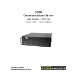
User Manual
Canoga Perkins
9119
Rack Mount
100BASE-TX/FX
Media Converter
Canoga Perkins
9119 Media Converter
NOTICE
Canoga Perkins reserves the right to change or update the contents of this manual and to change the specifications of its products at any time without prior notification. Every effort has been made to keep the information in this document current and accurate as of the date of publication or revision. However, no guarantee is
given or implied that the document is error free or that it is accurate with regard to any specification.
Canoga Perkins has prepared this manual for use by customers and Canoga Perkins personnel as a guide for
the proper installation, operation and/or maintenance of Canoga Perkins equipment. The drawings, specifications and information contained in this document are the property of Canoga Perkins and any unauthorized
use or disclosure of such drawings, specifications and information is prohibited.
Canoga Perkins Corp.
20600 Prairie Street
Chatsworth, CA 91311-6008
(818) 718-6300
FAX: (818) 718-6312
Web Site: http://www.canoga.com
email: [email protected]
Copyright 1999 - 2005 Canoga Perkins
All Rights Reserved
9119 100BASE-TX to Fiber Media Converter
Part Number 6911560, Rev. G 09/2005
To reference Technical Advisories and Product Release Notes, go to Canoga Perkins' website:
http://www.canoga.com
3
Canoga Perkins
9119 Media Converter
9119 100BASE-TX/FX
Media Converter
4
Canoga Perkins
9119 Media Converter
Caution!
This product may contain a laser diode emitter operating at a wavelength of 1300nm - 1600nm. Use of optical instruments (for example: collimating optics) with this product may increase eye hazard. Use of controls or adjustments or
performing procedures other than those specified herein may result in hazardous radiation exposure.
Under normal conditions, the radiation levels emitted by this product are under the Class 1 limits in 21 CFR Chapter 1,
Subchapter J.
ATTENTION!
Cet équipement peut avoir une diode laser émettant à des longueurs d'onde allant de 1300nm à 1600nm. L'utilisation
d'instruments optiques (par exemple : un collimateur optique) avec cet équipement peut s'avèrer dangereuse pour les yeux.
Procéder à des contrôles, des ajustements ou toute procédure autre que celles décrites ci-après peut provoquer une
exposition dangereuse à des radiations.
Sous des conditions normales, le niveau des radiations émises par cet équipement est en dessous des limites prescrites
dans CFR21, chapitre 1, sous chapitre J.
Notice!
This device contains static sensitive components. It should be handled only with proper Electrostatic Discharge
(ESD) grounding procedures.
NOTE!
Cet équipement contient des composants sensibles aux décharges électro-statiques. Il doit absolument être manipulé en respectant les règles de mise à la terre afin de prévenir de telles décharges.
5
Canoga Perkins
9119 Media Converter
9119 Table of Contents
1. Introduction .................................................................................................................. 9
1.1 Ship List ................................................................................................................................................... 9
1.2 Applications .......................................................................................................................................... 10
2. Setup and Installation ..............................................................................................11
2.1 Overview ............................................................................................................................................... 11
2.2 Unpacking .............................................................................................................................................. 12
2.3 Setup of the 9119 Media Converter ....................................................................................................... 12
2.3.1 UTP Connection ................................................................................................................................ 12
2.3.2 Fiber Connection ............................................................................................................................... 12
2.3.3 Relay Connections ............................................................................................................................. 13
2.4 Installing the 9119 Media Converter .................................................................................................... 13
2.4.1 Stand Alone Unit ................................................................................................................................. 14
2.4.2 Rack Mount Installation ..................................................................................................................... 14
2.4.3 10/100 Auto Negotiation Application Note ....................................................................................... 15
2.4.4 Fiber Link Loss Forwarding Application Note .................................................................................. 15
3. Operation ................................................................................................................... 17
3.1 LED Indicators ...................................................................................................................................... 17
3.2 Loss Budget ........................................................................................................................................... 18
3.2.1 100BASE-FX Multimode (MM) 1310nm LED ................................................................................. 18
3.2.2 100BASE-FX Single Mode (SM) 1310nm LP Laser ......................................................................... 19
3.2.3 100BASE-FX Single Mode (SM) 1310nm LD Laser ........................................................................ 19
3.2.4 100BASE-FX Single Mode (SM) 1550nm XD Laser ........................................................................ 19
4. Troubleshooting ........................................................................................................ 21
5. Technical Specifications ........................................................................................... 23
5.1 100BASE-FX Multimode (MM) 1310nm MM LED ............................................................................ 23
5.2 100BASE-FX Single Mode (SM) 1310nm LP Laser ............................................................................ 23
5.3 100BASE-FX Single Mode (SM) 1310nm LD Laser ........................................................................... 24
5.4 100BASE-FX Single Mode (SM) 1550nm XD Laser ........................................................................... 24
5.5 Electrical / Functional ............................................................................................................................ 25
5.6 Physical / Environmental ....................................................................................................................... 25
6. Glossary .................................................................................................................... 27
Appendix A .................................................................................................................... 29
6
Canoga Perkins
9119 Media Converter
List of Figures
1-1 9119 Typical Application ..................................................................................................................................... 10
1-2 9119 NIC Connection .......................................................................................................................................... 10
2-1
2-2
2-3
2-4
2-5
2-6
Top, Front and Rear Views of 9119 Media Converter ......................................................................................... 11
UTP Connector for 9119 Media Converter .......................................................................................................... 12
Fiber Optic Cable Connections on Rear Panel ..................................................................................................... 13
Relay Terminal Block ........................................................................................................................................... 13
9101 LAN Chassis ................................................................................................................................................ 14
Fiber Break Responses ......................................................................................................................................... 15
3-1 9119 LED Indicators ............................................................................................................................................ 17
7
Canoga Perkins
9119 Media Converter
This page is intentionally left blank.
8
Canoga Perkins
9119 Media Converter
1. Introduction
The Canoga Perkins Model 9119 100BASE-TX to FX Media Converter provides 100Mbps fiber optic connectivity between 100Mbps switches and/or work stations.
The 9119 Media Converter allows users who already possess Fast Ethernet switches to convert from a 100BASE-TX UTP
interface to a 100BASE-FX-based single mode fiber optic interface and exceed the 100BASE-FX multimode limitation of
2km on fiber optic cable, in full-duplex (FDX) mode and achieve greater than 100km connectivity.
The 9119 Media Converter is also especially suited for harsh manufacturing environments where immunity to noise and
electrical / magnetic interference or security considerations are of particular importance. Conforms to NEBS Level 3
Standards.
The 9119 Media Converter comes in four versions:
•
•
•
•
100BASE-FX 1310nm Multimode (MM) LED (11dB loss budget)
100BASE-FX 1310nm Single Mode (SM) LP Laser (10dB loss budget)
100BASE-FX 1310nm Single Mode (SM) LD Laser (26dB loss budget)
100BASE-FX 1550nm Single Mode (SM) XD Laser (26dB loss budget)
The 9119 Media Converter has the following features:
•
•
•
•
•
•
•
•
•
•
•
Converts UTP interfaces to fiber
Link Loss Forwarding from fiber port to the UTP interface
Remote Fault Detection and Alarm Forwarding on the fiber interface
Normal or crossed-over UTP connections
Dry Contact Alarm Relays
Provides noise / interference immunity
Provides virtually untappable security
Distance exceeding 100km on fiber
Single Mode or Fiber Support (Multimode)
Six status LED indicators
ST and SC connectors
1.1 Ship List
The following items are included:
•
•
•
•
•
9119 Media Converter
User Manual
Wall-Mount Power Supply with 6-foot power cord
Tie Wrap/Velcro Kit
Ten-foot Category 5, Twisted Shielded Pair (STP) patch cable
9
Canoga Perkins
9119 Media Converter
1.2 Applications
Figure 1-1 shows a typical application allowing a full-duplex link at a distance of up to 100km.
Figure 1-2 illustrates an application where a PC housing a 10/100 network interface card (NIC), with an RJ connector, would
enable a fiber connection to a desk top application. The 9119 Media Converter would attach to the 100BASE-TX port via a
Category 5 UTP patch cable.
Figure 1-1
9119 Typical Application
Figure 1-2
9119 NIC Connection
10
Canoga Perkins
9119 Media Converter
2. Setup and Installation
2.1 Overview
This section details the unpacking, setup, and the options for installing the 9119 Media Converter. Figure 2-1 shows the
top, front and rear views of the 9119 Media Converter.
Figure 2-1
Top, Front and Rear Views of 9119 Media Converter
11
Canoga Perkins
9119 Media Converter
2.2 Unpacking
Canoga Perkins products are carefully inspected and tested prior to shipment from the factory. It is recommended that you
keep the shipping package until the unit has been installed and verified as being fully operational. In the unlikely event that
the unit is defective, contact the Canoga Perkins Customer Service department for a Return Material Authorization (RMA)
number. For directions on how to return the unit refer to Appendix A.
Canoga Perkins products, like all electronic devices with static sensitive components, should be handled with care. Since
there are no user-serviceable parts inside the unit, opening the case will void the factory warranty.
2.3 Setup of the 9119 Media Converter
The 9119 UTP-to-Fiber Media Converter requires its own power source. The 9119 Media Converter is supplied with a wallmount power supply that requires 90-130VAC at 50-60Hz and provides +5VDC to the unit. The AC power supply connects
to the 9119 via the 5VDC power connection. An optional 220V power supply is available or the unit can be rack mounted
in the 9101 LAN Chassis.
2.3.1 UTP Connection
The 9119 Media Converter features a 8-pin modular RJ style connector on the UTP side of the network (see Figure 2-2).
Both normal and internally crossed-over connections are provided to accommodate straight-through patch cable connections to any type of 100BASE-TX port.
Caution: To protect the Ethernet port from an intrabuilding lightening surge, use a properly grounded shielded
cable.
Figure 2-2
UTP Connection for 9119 Media Converter
To assure a correct connection, connect one end of a standard "straight-through" UTP cable to the 100BASE-TX port of the
LAN device. If this port is marked with an X, connect the other end to the 9119s NORM jack. Otherwise, connect the other
to the 9119s X jack. (One and only one end of the cable should be connected to an X jack).
2.3.2 Fiber Connection
The 9119 Media Converter connects to fiber optic cable via a duplex SC or ST type connector on the rear panel (see Figure
2-3).
Connect the Tx of one device to the Rx of the other, and vice-versa. When working with fiber optic cables and connectors,
care should be taken to prevent contaminating connector plugs and sleeves. Dirt and dust can significantly affect connector
insertion loss and consequently degrade performance.
12
Canoga Perkins
9119 Media Converter
Figure 2-3
Fiber Optic Connections on Rear Panel
2.3.3 Relay Connections
The 9119 Media Converter features dry-contact alarm relays. These contacts are available via a removable terminal block
on the rear panel (see Figure 2-4).
Figure 2-4
Relay Terminal Block
The relays monitor each interface's Link Integrity, plus the Remote (Fiber) Fault status. In addition, the UTP Interface
relay is configured such that power failure will result in the same state as a status alarm (i.e., loss of link).
The description of the alarm contacts is the following:
NO
Normally Open. This means open during Normal, non-fault operation; closed during a fault condition.
NC
Normally Closed. This means closed during Normal, non-fault operation; open during a fault condition.
C
Common. Common terminal between alarm contacts.
2.4 Installing the 9119 Media Converter
The 9119 Media Converter is an easy to install device and can be installed in the Canoga Perkins Model 9101 LAN Chassis,
attached to vertical or horizontal surfaces, or used in a table top configuration. As with all electronic devices, adequate air
flow should be provided around the unit since some heat is generated.
The 9119 should not be placed on top of another device that also generates heat. The cumulative heat can cause the internal
temperature of the 9119 to exceed its design specifications which could potentially lead to inconsistent operation.
13
Canoga Perkins
9119 Media Converter
2.4.1 Stand Alone Unit
In addition to being placed on a desk top, the 9119 stand alone can be attached to the side of any surface (PC, cabinet, desk,
etc.). An attachment kit is shipped with the 9119 stand alone unit for this purpose.
Wherever the unit is mounted, the decision for the location will include determining a mounting place for a transformer as
well. The power supply is furnished with a 6-foot power cord. The connector for the power supply is located on the rear
panel of the unit.
2.4.2 Rack Mount Installation
Up to twelve 9119 Media Converters can be inserted into a Canoga Perkins Model 9101 LAN Chassis for high-density
installation (see Figure 2-5). For rack-mount applications requiring alarm-relay usage, it is recommended to remove the
relay terminal blocks, connect the alarm leads, and then reinstall after the 9119s are mounted in the rack. Refer to the Model
9101 LAN Chassis User Manual for 9119 installation instructions.
Figure 2-5
9101 LAN Chassis
14
Canoga Perkins
9119 Media Converter
2.4.3 10/100 Auto Negotiation Application Note
The 100BASE-FX specification for fiber optic interfaces as implemented in the 9119 media converter, does not provide
support for the auto negotiation of speed or mode. Therefore, any attachment to the 9119 fiber optic interface must be
100Mbps. The 9119 optical interfaces are fixed Full-duplex (FDX) devices that also support half-duplex (HDX) port attachments.
While the 9119 supports the 100BASE-TX interface specifications for speed and mode, it does not implement the N-Way
auto negotiation feature that communicates speed and mode changes (10 to 100Mbps and HDX to FDX) between UTP
interfaces. In order to support N-Way speed changes, packet buffering, which flow controls frames from the 100Mbps
interface down to a 10Mbps interface, must be implemented for normal operation. Since packet buffering is typically employed in layer 2 switches, and not the physical layer, the 9119 does not provide buffering, cannot support speed changes
and must operate at 100Mbps.
Since N-Way auto negotiation is normally implemented in 100BASE-TX switch interfaces, if left to auto negotiate with the
9119 fixed interface, there is a strong likelihood that it will default to HDX operation rather than FDX. Since most 100Mbps
circuits require FDX data transfer for optimal operation, defaulting to the lowest speed (100Mbps in the case of the 9119)
and lowest mode, (HDX rather than FDX) can potentially cause operational issues.
Therefore, where practical, rather than allow the interface to auto negotiate with the fixed 9119 UTP interface, it is recommended that the switch interface be set to 100Mbps and the users choice of mode (HDX/FDX).
2.4.4 Fiber Link Loss Forwarding Application Note
The 9119 Media Converter incorporates a Fiber Link Loss Forwarding feature which allows indirect sensing of a Fiber Link
Loss via the 100BASE-TX UTP connection. Whenever the 9119 Media Converter detects a Link Loss condition on the
Receive fiber (Fiber LNK OFF), it disables its UTP transmitter so that a Link Loss condition will be sensed on the UTP port
to which the 9119 Media Converter is connected. (See Figure 2-6). This link loss can then be sensed and reported by a
Network Management agent in the remote UTP port's host equipment.
Figure 2-6
Fiber Break Responses
This feature has no effect on the 9119s UTP LNK LED, which continues to function normally, independent of the state of
the Fiber LNK LED and the UTP transmitter.
NOTE: Some UTP interfaces will disable the transmission of idle signals towards the 9119, when a loss of link from
the 9119 is detected. The 9119 does not disable the UTP Port and will show link if the attached UTP interface
continues to send good link pulses.
In addition, the 9119 will invoke LLF when a legitimate remote fault alarm (RMTF) is received from the
remote 9119. This implies that the local 9119 transmitter, remote receiver, or cable between the two, is
faulty.
15
Canoga Perkins
9119 Media Converter
This page is intentionally left blank.
16
Canoga Perkins
9119 Media Converter
3. Operation
3.1 LED Indicators
The 9119 Media Converter has six LED indicators on the front panel (see Figure 3-1).
Figure 3-1
9119 LED Indicators
PWR
Power Indicator (Green)
When lit, PWR indicates that the unit is receiving power.
LNK Fiber/Interface Integrity Indicator
(Fiber) (Green)
When lit, LNK indicates that sufficient modulated light energy is being received by the Fiber interface.
When this indicator turns off, the 9119 Media Converter will transmit a Remote Fault to the remote fiber optic
interface, and through LLF, will disable its local UTP transmitter, causing a loss of Interface Integrity at the local
UTP device.
Rx
Receive Data, Fiber to UTP (Green)
When lit, Rx indicates that the converter is receiving packets via the fiber optic cable.
Tx
Transmit Data, UTP to Fiber (Green)
When lit, Tx indicates that the converter is receiving packets via the UTP cable and is attempting to transmit them
via the fiber optic cable.
RMTF Remote Fault (Red)
Remote Fault Indication (RMTF) is a featurethat is complimentary to LLF. It is essentially a means by which error
conditions are echoed back to the unit that is potentially causing errors. Upon loss of link integrity on a fiber
optic port, the remote device transmits an RMTF pulse from its Tx port to the local device, indicating an error
condition on the Tx port or that the fiber optic link may have failed.
This feature allows the local unit to become "aware" of fault conditions that it is possibly creating. Upon receipt of
the RMTF signal, the local unit, be it a 9119, 9135, or 9140, will illuminate the RMTF Indicator and invoke LLF
on the local interface.
NOTE: The following additional effects may also be generated by the receiving device, depending upon the equipment and
configuration:
•
•
•
•
9119s will close dry relay alarm contacts reserved for RMTF.
LLF on the UTP port will propagate the failed condition to the attached DTE device.
Non-managed 9135/9140s, when LLF is enabled on the 100BASE-FX interface will also propagate the
failure condition to the attached DTE device.
Managed 9135/9140s generate TRAP 43 "remote fault on port 2" both in-band and out-of-band via SLIP
port if so configured (and dry relay contact closure).
17
Canoga Perkins
9119 Media Converter
This feature is equally supported on the following configurations:
• 9135/9140 & 9135/9140
• 9135/9140 & 9119
This feature is enabled by default on all 9119 converters and its functionality cannot be inactivated.
Link Loss Forwarding (LLF) - (There is no LED indicator associated with this functionality):
This feature is supported by the UTP 10 or 100Mbps Ethernet interface. Upon loss of link integrity on a fiber optic interface
port (possibly due to a loss of signal from a remote unit), the UTP interface port subsequently shuts off. The link loss status
is thereby forwarded to the downstream DTE device. This results in a forced failure on the downstream UTP port which also
loses link integrity. In the event the DTE device is an SNMP managed device, it will emit a TRAP to the NMS trap host
indicating that the UTP port is "down" or lost link integrity.
This feature has been added on all 8829 and 9119 devices and cannot be disabled.
LNK 100BASE-TX / Interface Integrity
(UTP) Indicator (Green)
When lit, LNK indicates that a modulated signal of sufficient amplitude is being received by the UTP interface.
3.2 Loss Budget
A Loss Budget reflects the difference between a transceiver's Average Transmit Power and its Average Receiver Sensitivity.
The loss budget for the 9119 Media Converter varies with its type as is shown below.
Loss Budgets (Guaranteed. Typically 2db greater)
•
•
•
•
100BASE-FX 1310nm Multimode (MM) LED (11dB loss budget)
100BASE-FX 1310nm Single Mode (SM) LP Laser (10dB loss budget)
100BASE-FX 1310nm Single Mode (SM) LD Laser (26dB loss budget)
100BASE-FX 1550nm Single Mode (SM) XD Laser (26dB loss budget)
3.2.1 100BASE-FX 1310nm Multimode (MM) LED
The 9119 100BASE-FX Media Converter features a minimum Average Transmit Power of -20dBm and a minimum Average Receiver Sensitivity of -31dBm, assuming 62.5µm core (Multimode) fiber. This yields a maximum loss budget of
11dB, per ANSI X3.166 and ISO/IEC 9314-3.
The general rule when figuring total link loss; allow 0.5dB per connector (devices and patch panel connections) plus 4dB
per km attenuation on 62.5/125 micron cable.
18
Canoga Perkins
9119 Media Converter
3.2.2 100BASE-FX Single Mode (SM) 1310nm LP Laser
The 9119 "1310nm Single Mode" Laser Media Converter features an Average Transmit Power of at least -20dBm, and a
minimum Average Receiver Sensitivity of -31dBm. Allowing for a Transmission Penalty of 1dB, this yields a typical loss
budget of 10dB, per ANSI X3.184.
When working out the cable and circuit attenuation, the user should allow 0.5dB loss per connector for all devices and patch
panel connections, plus 0.5dB loss per km on 8-10/125 micron cable. For a more precise treatment of Cable Plant issues, the
reader is referred to Annex C of ANSI X3.184, "Cable Plant Usage."
3.2.3 100BASE-FX Single Mode (SM) 1310nm LD Laser
The 9119 "1310nm Long Distance Single Mode" Media Converter features an Average Transmit power of at least -4dBm, and
a minimum Average Receiver Sensitivity of -31dBm. Allowing for a Transmission Penalty of 1dB, this yields a loss budget of
26dB, which is much more conservative than that specified in ANSI X3.184 (SMF/PMD Category II).
This is because the ANSI specification references a bit error rate of 2.5 x 10⁻¹⁰ which is too large to be of practical use at
100Mbps. For this reason, Canoga Perkins prefers to specify the same sensitivity as Category I interfaces. Typically, performance will be at least 2dB better than specified. Also, per this ANSI specification, a minimum attenuation of 15dB is
required between transmitter and receiver to prevent overdriving the receiver. This interface option is not recommended for
Half-Duplex (CSMA/CD) applications, due to the minimum attenuation required.
When working out the cable and circuit attenuation, the user should allow 0.5dB loss per connector for all devices and patch
panel connections, plus 0.5dB loss per km on 8-10/125 micron cable. For a more precise treatment of Cable Plant issues, the
reader is referred to Annex C of ANSI X3.184, "Cable Plant Usage." Mixing Category I and Extended Media Converters at
either end of a fiber optic cable is not recommended, since the different driver powers and receiver specifications would
limit the link to fall within a minimum of 14dB attenuation and a maximum of 16dB to assure proper operation, assuming
equal length fibers.
3.2.4 100BASE-FX Single Mode (SM) 1550nm XD Laser
The 9119 "1550nm Long Distance Single Mode" Media Converter features an Average Transmit power of at least -4dBm, and
a minimum Average Receiver Sensitivity of -31dBm. Allowing for a Transmission Penalty of 1dB, this yields a loss budget of
26dB, which is much more conservative than that specified in ANSI X3.184 (SMF/PMD Category II).
This is because the ANSI specification references a bit error rate of 2.5 x 10⁻¹⁰ which is too large to be of practical use at
100Mbps. For this reason, Canoga Perkins prefers to specify the same sensitivity as Category I interfaces. Typically, performance will be at least 2dB better than specified. Also, per this ANSI specification, a minimum attenuation of 15dB is
required between transmitter and receiver to prevent overdriving the receiver. This interface option is not recommended for
Half-Duplex (CSMA/CD) applications, due to the minimum attenuation required.
When working out the cable and circuit attenuation, the user should allow 0.5dB loss per connector for all devices and patch
panel connections, plus 0.5dB loss per km on 8-10/125 micron cable. For a more precise treatment of Cable Plant issues, the
reader is referred to Annex C of ANSI X3.184, "Cable Plant Usage." Mixing Category I and Extended Media Converters at
either end of a fiber optic cable is not recommended, since the different driver powers and receiver specifications would
limit the link to fall within a minimum of 14dB attenuation and a maximum of 16dB to assure proper operation, assuming
equal length fibers.
19
Canoga Perkins
9119 Media Converter
This page is intentionally left blank.
20
Canoga Perkins
9119 Media Converter
4. Troubleshooting
In the case of the 9119 Media Converter, a hybrid device, there are two LNK LED indicators, marked Fiber LNK and UTP
LNK. When the 9119 Media Converter is put into service, and if all cables are correctly connected and there are UTP and fiber
optic devices attached to the cable, both LNK indicators should illuminate. If either LNK Indicator does not illuminate, check
the appropriate attached cable and remote transmitter to ensure they are connected properly. If the UTP LNK Indicator still
does not illuminate, try the alternate UTP connector, which provides the opposite Transmit-to-Receive crossover routing.
This implies that if the LNK indicator is illuminated on the local device, the remote transmitter, the attached cable and the
local receiver are operational. In addition, the 9119 Media Converter supports Far End Fault operation on the Fiber Optic
interface, if connected to a unit with similar capability at the remote end. Thus, if the RMTF LED indicator is illuminated, it
indicates a problem with either the local fiber transmitter, the attached cable, or the remote fiber receiver.
The 9119 Media Converter's Link Loss Forwarding (LLF) feature will disable the UTP transmitter whenever the Fiber LNK
LED indicator is off. This allows the fiber failure to be sensed by a management agent at the remote UTP port as a UTP Link
failure. Therefore, whenever the UTP transmitter appears to be off, check the receive fiber cable connections to the 9119
media converter and ensure the F/LNK LED indicator is illuminated.
If the Power LED indicator and both LNK indicators are illuminated, and the RMTF indicator is off, you can assume with
some assurance that the problem exists elsewhere. Data transfer through the 9119 Media Converter can only take place
when both LNK indicators are illuminated and the RMTF indicator is off. The most common cause of network problems,
once physical layer problems are resolved, is software configurations.
In addition, check that the total link loss is within the allowable fiber optic loss budget, and that the proposed application
is within normal IEEE 802.3 Propagation Delay Budget parameters for Half-Duplex (CSMA/CD) applications.
If this still does not solve the problem, call the Canoga Perkins Service Department at (818) 718-6300. A 24-hour hotline,
(800) 360-6642, is available for emergency repair situations.
21
Canoga Perkins
9119 Media Converter
This page is intentionally left blank.
22
Canoga Perkins
9119 Media Converter
5. Technical Specifications
5.1 100BASE-FX Multimode (MM) 1310nm LED
Emitter Type:
LED
LED Center Wavelength:
1310nm nominal
LED Spectral Width:
Per ANSI X3.166 and ISO/IEC 9314-3
LED Rise/Fall Times 10% / 90%:
<3.5nsec.
Transmit Power (Avg.):
-20dBm minimum (62.5/125 micron fiber)
Detector Type:
PIN Photodiode
Receive Sensitivity (Avg. Power):
-31dBm minimum
Loss Budget:
11dB (62.5/125 micron fiber)
Optical Connector:
Duplex SC or ST
Bit Error Rate:
Better than 1 in 10-10 (per 802.3 Spec.)
Mean Time Between Failures:
>100,000 hours
5.2 100BASE-FX Single Mode (SM) 1310nm LP Laser
Emitter Type:
Laser Diode
LED Center Wavelength:
1310nm nominal
Transmit Power:
(8/125 micron fiber) -20dBm minimum
Detector Type:
PIN Photodiode
Receive Sensitivity:
-31dBm minimum
Loss Budget:
10dB (8/125 micron fiber)
Optical Connector:
Duplex SC or ST
Bit Error Rate:
Better than 1 in 10-10
Mean Time Between Failures:
>100,000 hours
23
Canoga Perkins
9119 Media Converter
5.3 100BASE-FX Single Mode (SM) 1310nm LD Laser
Emitter Type:
Laser Diode
LED Center Wavelength:
1310nm nominal
Transmit Power:
-4dBm minimum (8/125 micron fiber)
Detector Type:
PIN Photodiode
Receive Sensitivity:
-31dBm minimum
Minimum Required Attenuation:
15dB
Loss Budget:
26dB (8/125 micron fiber)
Optical Connector:
Duplex SC or ST
Bit Error Rate:
Better than 1 in 10-10
Mean Time Between Failures:
>100,000 hours
5.4 100BASE-FX Single Mode (SM) 1550nm XD Laser
Emitter Type:
Laser Diode
LED Center Wavelength:
1550nm nominal
Transmit Power:
-4dBm minimum (8/125 micron fiber)
Detector Type:
PIN Photodiode
Receive Sensitivity:
-31dBm minimum
Minimum Required Attenuation:
15dB
Loss Budget:
26dB (8/125 micron fiber)
Optical Connector:
Duplex SC or ST
Bit Error Rate:
Better than 1 in 10-10
Mean Time Between Failures:
>100,000 hours
24
Canoga Perkins
9119 Media Converter
5.5 Electrical / Functional
Interface:
ISO/IEC 8802.3
100BASE-TX; IEEE
802.3 100BASE-FX
Relays:
2A, 3VDC max.
Connectors:
Fiber: Duplex SC and ST per ANSI X3.237-1995
UTP: ISO/IEC 8877: 1992 - Jack (RJ-45)
Relay Terminals: Weco 121-A-111/09 or equivalent
22-12 AWG, 7mm / .28 in. Stripping Length
Average One-Way Latency:
190nsec, max.
5.6 Physical / Environmental
Enclosure:
Stand Alone Metal Housing
Dimensions:
6.0"L x 3.4"W x 1.0" H
Weight:
8 oz.
Power Supply:
External Wall Mount Type
• Dimensions: 3"L x 2"W x 1.6"D
• Power Consumption: 5W max. @ 110VAC 60Hz
5W max. @ 220VAC 50Hz
• Power Cord: 6 feet
Operating Temperature:
0° - 40°C
Humidity:
10 - 90% (non-condensing)
Compliance:
NEBS Level 3 Compliant
25
Canoga Perkins
9119 Media Converter
This page is intentionally left blank.
26
Canoga Perkins
9119 Media Converter
6. Glossary
CSMA/CD
Carrier Sense Multiple Access with Collision Detection
FDDI
Fiber Distribution Data Interface
FDX
Full-Duplex
LED
Light Emitting Diode
NEBS
Network Equipment Building Systems
NIC
Network Interface Card
nm
nanometer
SMF/PMD
Single-Mode Fiber / Physical Media Dependent
UTP
Unshielded Twisted Pair
27
Canoga Perkins
9119 Media Converter
This page is intentionally left blank.
28
Canoga Perkins
9119 Media Converter
Appendix A Warranty
Limited Lifetime Warranty
Effective July 1, 2005 and After, Canoga Perkins warrants that, at the time of sale, and, for its lifetime, with certain
exceptions noted below, every Canoga Perkins' labeled product purchased will be free from defects in material and
workmanship for its lifetime, if properly installed and used in conformity to Canoga Perkins' published specifications.
This warranty covers the original user only and is not transferable. For the purposes of this Warranty, "lifetime" is
defined as the serviceable life of the product (a minimum of 5 years) or any longer period during which replacement spare
parts are available. Subject to the conditions and limitations set forth below, Canoga Perkins will, at its option, either
repair or replace any part of its product(s) that prove defective by reason of improper workmanship or materials. The
warranty period for power supplies, fans and optics is five (5) years. Consumables such as filters are covered for one
year. Software is warranted for 90 days. Hardened Media Converter (HS) products are covered for three (3) years.
This warranty does not cover any damage to products that have been subjected to lightning or other Acts of Nature,
misuse, neglect, accident, damage, improper installation, or maintenance, including over-voltage failures caused by use
outside of the product’s specified rating, normal wear and tear of mechanical components, or alteration or repair by
anyone other than Canoga Perkins or its authorized representative. If the user is unsure about the proper means of
installing or using the equipment, contact Canoga Perkins' free technical support services. Customer must notify Canoga
Perkins promptly in writing of any claim based on warranty. Canoga Perkins is not liable for, and does not cover under
warranty, any costs associated with servicing and/or the installation of its products or for any inspection, packing or
labor costs in connection with return of goods. In the event Canoga Perkins breaches its obligation of warranty,
customer's sole and exclusive remedy is limited to replacement, repair, or credit of the purchase price, at Canoga Perkins'
option. Under no circumstance will Canoga Perkins be liable for consequential or incidental damages or loss of profits.
Warranty Registration
To establish original ownership and to record purchase date, please complete the warranty on-line form on our product
registration page. URL: www.canoga.com/warranty
Optional Service Programs
Canoga Perkins offers several optional Service Programs. Please call Canoga Perkins Sales Department (818-718-6300) or
see our web site (www.canoga.com) for details.
CUSTOMER SERVICE DEPARTMENT REPAIR WARRANTY
Repairs performed by the Canoga Perkins Customer Service Department will be free from defects in material and
workmanship for a period of ninety (90) DAYS from the date the repaired product is shipped, or until the expiration of the
original factory warranty, whichever is longer.
29
Canoga Perkins
9119 Media Converter
Limitations
Canoga Perkins may at its sole discretion modify its Limited Warranty at any time and from time to time.
Other than those expressly stated herein, THERE ARE NO OTHER WARRANTIES OF ANY KIND, EXPRESSED OR
IMPLIED, AND SPECIFICALLY EXCLUDED BUT NOT BY WAY OF LIMITATION, ARE THE IMPLIED WARRANTIES
FOR FITNESS FOR A PARTICULAR PURPOSE AND MERCHANTABILITY. IT IS UNDERSTOOD AND AGREED
CANOGA PERKINS' LIABILITY WHETHER IN CONTRACT, IN TORT, UNDER ANY WARRANTY, IN NEGLIGENCE OR
OTHERWISE SHALL NOT EXCEED THE AMOUNT OF THE PURCHASE PRICE PAID BY THE CUSTOMER AND
UNDER NO CIRCUMSTANCES SHALL CANOGA PERKINS BE LIABLE FOR SPECIAL, INDIRECT, INCIDENTAL OR
CONSEQUENTIAL DAMAGES. THE PRICE STATED FOR THE EQUIPMENT IS A CONSIDERATION IN LIMITING
CANOGA PERKINS' LIABILITY. NO ACTION, REGARDLESS OF FORM, ARISING OUT OF THE TRANSACTIONS OF
THIS AGREEMENT MAY BE BROUGHT BY CUSTOMER MORE THAN ONE YEAR AFTER THE CAUSE OF THE
ACTION HAS ACCRUED. CANOGA PERKINS' MAXIMUM LIABILITY SHALL NOT EXCEED AND CUSTOMER'S
REMEDY IS LIMITED TO EITHER (i) REPAIR OR REPLACEMENT OF THE DEFECTIVE PART OF PRODUCT, OR AT
CANOGA PERKINS' OPTION (ii) RETURN OF THE PRODUCT AND REFUND OF THE PURCHASE PRICE, AND SUCH
REMEDY SHALL BE CUSTOMER'S ENTIRE AND EXCLUSIVE REMEDY. AUTHORIZED RESELLERS ARE NOT
AUTHORIZED TO EXTEND ANY DIFFERENT WARRANTY ON CANOGA PERKINS' BEHALF.
Return Policy
Customer must obtain an RMA (Return Material Authorization) number from the Canoga Perkins Customer Service
Department before returning a product for service or repair.
Canoga Perkins' technical support department can be reached through any of the following means:
Telephone: 818-718-6300
Fax: 818-718-6312
E-Mail: [email protected]
If the warranty for a power supply, fan, optics, consumable or software has expired, customer must provide the Canoga
Perkins Customer Service Representative with a Purchase Order to authorize the repair.
Send the defective product postage and insurance prepaid to the address provided to you by Canoga Perkins' technical
support representative. Failure to properly protect the product during shipping may void this warranty. The return
authorization number must be written on the outside of the carton to ensure its acceptance.
The customer must pay for the non-compliant product(s) return transportation costs to Canoga Perkins for evaluation of
said product(s) for repair or replacement. Canoga Perkins will pay for the shipping of the repaired or replaced in-warranty
product(s) back to the customer (any and all customs charges, tariffs, or/and taxes are the customer’s responsibility).
Canoga Perkins reserves the right to charge for all testing and shipping incurred, if after testing, a return is classified as
"No Problem Found."
30