1
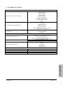
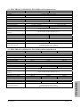
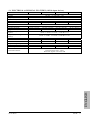
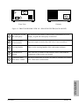
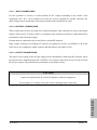
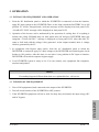
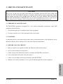
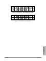
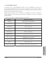
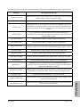
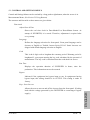
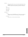
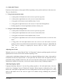
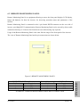
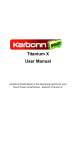
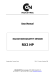
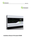
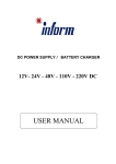
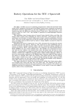
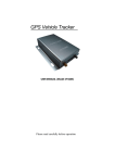
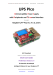
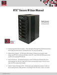
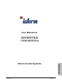
User Manual for
INVERTER
1500-5000VA
Ver1.0 Rev0
ENGLISH
Inform Inverter Systems
PAGE : 1
IMPORTANT
This users manual contains setup, operation and maintenance information for
Inverta Series DC/AC Static Inverter.
Before starting setup and operation of the equipment, complete users manual
should be read carefully.
Before operation, the inverter should be prepared by an authorized technical
person approved. The warranty will be void, if this direction is not followed.
Please contact customer service, if you see any problem about any process
described in this users manual.
The manufacturer reserves the right to change the design of the equipment without
notice.
ELECTROMAGNETIC COMPABILITY
This equipment if compatable to EMC directive 89/336/EEC and to conditions in
released technical specifications. The compability remains only if related
directions are followed and only if the equipment is used with accessories
approved by the manufacturer.
WARNING
This is an A class inverter product. In closed environments, it can cause radio
interference. In this case, extra precautions may be needed.
WARNING
ENGLISH
This equipment contains RFI filter. Ground current should’nt be higher than
3.5mA.
Ver1.0 Rev0
PAGE : 2
CAUTION
1. Do not open the cover. There are no user servicable parts inside.
2. Even after the equipment is disconnected from batteries and input connections,
a intervention to the interior of the equipment contains risk of electric shock.
3. Ventilation holes should be kept open and no objects should be inserted.
4. In the environment where the equipment will be operated, the temperature and
humidity should be relevant.
5. Magnetic computer equipments like diskets and CDs should be kept away at
least 30 cm from the inverter system.
6. The equipment can not be operated in an environment having flammable and
explosive devices.
CAUTION
ENGLISH
In this manual, all items including terms BYPASS, AC INPUT and
SYNCHRONISATION are only valid for devices having BYPASS input.
Ver1.0 Rev0
PAGE : 3
CONTENT
1.
2.
3.
4.
5.
5
1.1
SYSTEM
5
1.2
ADVANTAGES
6
1.3
GENERAL FEATURES
7
1.4
ELECTRICAL & PHYSICAL FEATURES (24Vdc input devices)
8
1.5
ELECTRICAL & PHYSICAL FEATURES (48Vdc input Devices)
8
1.6
ELECTRICAL & PHYSICAL FEATURES (110Vdc input devices)
9
SETUP
11
2.1
OPENING PACKAGE
11
2.2
CHOOSING PROPER PLACE
11
2.3
ELECTRICAL CONNECTION
11
OPERATION
14
3.1
INITIAL USE OF EQUIPMENT AND OPERATION
14
3.2
TURNING OF THE EQUIPMENT
14
SERVICE AND MAINTENANCE
15
4.1
PERIODICAL MAINTENANCE
15
4.2
FAILURES
15
4.3
BEFORE CALLING SERVICE
15
FRONT PANEL
16
5.1
STRUCTURE OF FRONT PANEL
16
5.2
MEASUREMENTS MENU
18
5.3
CONTROL AND SETTINGS MENUS
20
5.4
USING BUTTONS
22
OPTIONS
24
6.1
SMART PORT (RS232 Communications)
24
6.2
REMOTE MONITORING PANEL
25
6.3
SNMP COMMUNICATIONS
26
6.4
DRY CONTACTS (Dry Port)
26
ENGLISH
6.
GENERAL INTRODUCTION
Ver1.0 Rev0
PAGE : 4
1. GENERAL INTRODUCTION
1.1 SYSTEM
Inverta Series DC/AC Inverter’s are equipments produced to supply computer and communication
systems, called as critical load. Inverta Series DC/AC Inverters converts DC voltages like batteries
to AC voltage with desired voltage and frequency and suuplying AC power.
SLT Series Frequency Converter is a real ON LINE equipment with sinusodial output waveform,
having static transfer (BYPASS) system and all required protections.
Because the equipment is designed ONLINE, it feeds load continously with the stable voltage and
frequency generated by itself. Therefore, there is no interruption when the utility voltage fails and
recovers.
In an overload condition, the FC transfers the load to bypass line, if a bypass supply exist, otherwise
it disables output. When the overload condition disappears, load is again feeded with the energy
generated by the FC.
Static transfer system acts as the same and prevents an intteruption, when the FC is failed.
Basic components of the system and their functions are as following :
Inverter : Converts the DC voltage produced by the rectifier to stable and regulated voltage with
desired voltage and frequency.
Static transfer system : In normal conditions, it switches output voltage generated by the inverter to
the output of the FC. In case when the inverter fails to generate voltage in desired amplitude and
frequency, static transfer system switches bypass input supply to the ouput.
DC input : The equipment produces AC voltage, by inverting the DC input feeded from this source.
ENGLISH
Inverter block diagram is shown below.
Ver1.0 Rev0
PAGE : 5
BYPASS
INPUT
Bypass C.B.
TRANSFER
SYSTEM
DC INPUT
INVERTER
Inverter
output C.B.
SYSTEM
OUTPUT
(1 phase)
DC input
C.B.
Figure 1.1 INVERTER BLOCK DIAGRAM
1.2 ADVANTAGES
•
Real ON LINE topology with 1 phase sinusodial output waveform
•
Internal isolation transformer at output
•
Capability to drive nonlineer loads (computers and switch mode power supplies)
•
IGBT technology with high frequency switching
•
High reliability with microprocessor and smart drivers
•
2x16 character LCD display, showing measurements, status and alarm messages
•
Led displays for easy observation of Inverter status
•
Audible alarm
•
Bypass input (option)
•
Smart communication (RS232) and SNMP / HTTP support
•
Access to Inverter informations over Internet (option)
•
Ability to report Inverter status changes and failures via e-mail (option)
•
RFI filter at input and output for telecom applications
•
Language selection from front panel (Turkish / English)
•
Calibration of measurements from front panel
•
Rack mount cabinet
•
Ability to see total operation duration
Ver1.0 Rev0
ENGLISH
Advantages and properties of Inverta Series DC/AC Static Inverter are as following.
PAGE : 6
1.3 GENERAL FEATURES
INDICATIONS AND ALARMS
Digital Indicators (on LCD Display)
Alarm Messages (on LCD Display)
Led Indicators
Load Percentage
Output Voltage
Battery Voltage
Input Voltage
Inverter Frequency
Battery Percentage
Maximum Load Percentage
Synchronization Status
Alarms
Load on Bypass
Overload
Bypass Failure
Output Low / High
Over Temperature
Battery Voltage Too Low / Low / High
Short Circuit / IPM Fault
Load on Bypass
Load on INVERTER
Alarm
COMMNICATION & REMOTE MONITORING
Management and Monitoring
Dry Contact Outputs
HTTP / SNMP Compability
0°C / + 40°C
-20°C / + 50°C
%0 - %90 (non condensing)
2000 meters maximum
ENGLISH
PHYSICAL PROPERTIES
Operation Temperature
Storage Temperature
Relative Humidity
Operation Altitude
Dry Contact Informations
RS232 Serial Port (Megatec Protocol)
Remote Monitoring Panel
SNMP (Simple Network Management Protocol)
Load on INVERTER / Bypass
Battery Low / Normal
UNIX
LINUX
NOVELL
Windows 98
Windows XP
Ver1.0 Rev0
PAGE : 7
1.4 ELECTRICAL & PHYSICAL FEATURES (24Vdc input devices)
1500 VA
BYPASS INPUT
Voltage
Frequency
DC INPUT (BATTERY INPUT)
Voltage
Current (Maximum)
OUTPUT
Voltage
Current (Nominal)
Surge Current (for 5 seconds)
Frequency (Syncronized to
bypass)
Frequency (Running from
battery)
Power Factor (cos ϕ)
Permitted Active Power
Crest Factor
Output Voltage Shape
Total Harmonic Distortion
Overall Optimum Efficiency
2500 VA
110 Vac / 220 Vac ± %15
50 Hz / 60Hz / 83 Hz / 400Hz ± %15
20 Vdc – 40 Vdc
75 Adc
6.8 Aac / 13.6 Aac
9 Aac / 18 Aac
121 Adc
110 Vac / 220 Vac ± % 1
11.4 Aac / 22.8 Aac
12 Aac / 24 Aac
50 Hz / 60 Hz / 83 Hz / 400 Hz ± % 1
50 Hz / 60 Hz / 83 Hz / 400 Hz ± % 0.1
0.7
1050 W
2.5 : 1
1750 W
2:1
Sinus
<%3
> % 78
> % 81
6 minutes at 101% load - 10 seconds at 125% load
Linear between 101% - 125%
Direct off / bypass over 125% load
Overload Tolerance
1.5 ELECTRICAL & PHYSICAL FEATURES (48Vdc input Devices)
2000 VA
Overload Tolerance
Ver1.0 Rev0
3000 VA
5000 VA
110 Vac / 220 Vac ± %15
50 Hz / 60Hz / 83 Hz / 400Hz ± %15
48 Adc
40 Vdc – 80 Vdc
71 Adc
120 Adc
9.1 Aac / 18.2 Aac
16 Aac / 32 Aac
110 Vac / 220 Vac ± % 1
13.6 Aac / 27.2 Aac
24 Aac / 48 Aac
22.7 Aac / 45.4 Aac
25Aac / 50 Aac
50 Hz / 60 Hz / 83 Hz / 400 Hz ± % 1
50 Hz / 60 Hz / 83 Hz / 400 Hz ± % 0.1
0.7
2100 W
3500 W
2:1
2:1
Sinüs
<%3
> % 78
> % 81
> % 85
6 minutes at 101% load - 10 seconds at 125% load
Linear between 101% - 125%
Direct off / bypass over 125% load
1400 W
3:1
PAGE : 8
ENGLISH
BYPASS INPUT
Voltage
Frequency
DC INPUT (BATTERY INPUT)
Voltage
Current (Maximum)
OUTPUT
Voltage
Current (Nominal)
Surge Current (for 5 seconds)
Frequency (Syncronized to
bypass)
Frequency (Running from
battery)
Power Factor (cos ϕ)
Permitted Active Power
Crest Factor
Output Voltage Shape
Total Harmonic Distortion
Overall Optimum Efficiency
1.6 ELECTRICAL & PHYSICAL FEATURES (110Vdc input devices)
ENGLISH
4000 VA
5000 VA
7000 VA
10000 VA
BYPASS INPUT
Voltage
110 Vac / or 220 Vac ± %15
Frequency
50 Hz /or 60Hz / or 83 Hz ± %15
DC INPUT (BATTERY INPUT)
Voltage
90 Vdc – 140 Vdc
Current (Maximum)
ÇIKIŞ
Voltage
110 Vac / or 220 Vac ± % 1
36 Aac / 18.2 Aac
45.7 Aac / 22.2 Aac
63.2 Aac / 32.2 Aac
90 Aac / 45.4 Aac
Current (Nominal)
99 Aac / 40 Aac
100 Aac / 50 Aac
138 Aac / 70 Aac
198 Aac / 100Aac
Surge Current (for 5 seconds)
Frequency (Syncronized to
50 Hz / or 60 Hz / or 83 Hz / or 400 Hz ± % 1
bypass)
Frequency (Running from
50 Hz /or 60 Hz /or 83 Hz / or 400 Hz ± % 0.1
battery)
0.7
Power Factor (cos ϕ)
Permitted Active Power
3200 W
3500 W
4900 W
7000W
Crest Factor
3:1
3:1
3:1
3:1
Output Voltage Shape
Sinüs
Total Harmonic Distortion
<%3
Overall Optimum Efficiency
> % 85
> % 85
> % 87
> % 87
6 minutes at 101% load - 10 seconds at 125% load
Overload Tolerance
Linear between 101% - 125%
Direct off / bypass over 125% load
Ver1.0 Rev0
PAGE : 9
3
1
4
2
Front View
5
4
Görünüş
Figure 1.3 FRONT AND REAR VIEW OF 1 PHASE INVERTER (RACK MOUNT)
LCD display, keypad
and led displays
All monitoring and control of the inverter is performed via LCD
display, keypad and led displays located here.
2
Input and output
circuit breakers
Input and output circuit breakers (DC & AC) are located here.
3
Carrying handles
These are the carrying handles of the rack mount enclosure.
4
Heatsink hot air
exhaust
This is the hot air exhaust of the heatsink, where semiconductor
components of the inverter are located.
5
Connection panel,
cable inlets / outlets
All power connections of inverter are made to terminals are located
here. Cable inlet is from bottom.
ENGLISH
1
Ver1.0 Rev0
PAGE : 10
2. SETUP
2.1 OPENING PACKAGE
When the equipment is delivered to you, first to be examined is a possible damage during transport.
Therefore, examine the equipment carefully. For a possible future use, save the packet and wooden
pad of the inverter after unpacking.
2.2 CHOOSING PROPER PLACE
1. For a proper ventilation, minimum distance between the rear of the inverter and any nearby
object should me minimum 20 cm.
2. Choose a place with proper temperature and humidity. It is recommended that the room, where
the inverter will operate (including batteries) is cooled with an air conditioner (approximate 24
°C )
3. Do not choose any place which can cause dust and corrosion.
4. The place chosen should not have direct sunshine and shouldnt be near any heating source.
5. Operating the equipment in proper conditions will increase the life of batteries.
6. Rack mount models can be installed to standart rack cabinets.
2.3 ELECTRICAL CONNECTION
All required connections to connection panel of inverter should be made by service personnel or by
the approval of service personnel.
Ground must be connected to the distribution panel. Otherwise, all loads connected to the output of
the inverter will be without ground connection.
CAUTION !!!
Connect and control ground (PE) connection. Definitly, the equipment should’nt be operated
without ground connection.
Ver1.0 Rev0
PAGE : 11
ENGLISH
Distribution to load can be done from the output terminals on the connection panel on the rear side
of the inverter. Pay attention, that the load distribution cables and outlets has ground connection.
2.3.1 ELECTRICAL CONNECTION FOR ONE PHASE INPUT DEVICES (10-15 kVA)
Before making connections of the equipment, All circuit breakers on the connection panel of the
inverter must be in OFF position.
A view of the connection panel and its terminals are given below.
ENGLISH
K1
K2
K3
K4
K5
K6
Battery - Input
Bypass Phase
Bypass Neutral
Outout Phase
Output Neutral
Ground
Battery + Input
Ground connection terminal (green – yellow)
DC (Battery) + pole connection terminal
DC (Battery) - pole connection terminal
AC Bypass supply (optional) phase connection terminal
AC Bypass supply (neutral) phase connection terminal
Output phase connection terminal
Output neutral connection terminal
PE
PE
K1
DC INPUT
K2
K3
AC INPUT
K4
K5
OUTPUT
K6
Figure 2.1 INVERTER CONNECTION TERMINALS
Ver1.0 Rev0
PAGE : 12
2.3.1.1 INPUT CONNECTIONS
For the operation of inverter, a certain amount of DC voltage depending on the model of the
equipment (24V, 48V, 110V) should be fed into the inverter, through K1 and K2 terminals. DC
input voltage can be obtained by connecting certain amount of batteries in series.
2.3.1.2 BATTERY CONNECTIONS
These connections needs to be made to K3 and K4 terminals. This connection is used as the bypass
supply of the inverter, it means, if there is a problem in the operation of inverter, output load will be
automaticly feeded from this supply.
Ground must be connected to green and yellow colored PE terminal.
Input voltage connected to terminals K3 and K4 are applied to inverter via BYPASS C.B. in the
front access of te equipment, which connects and disconnects only phase circuit.
2.3.1.3 OUTPUT CONNECTIONS
The phase of the voltage at the inverter output can be distributed to loads from K5 terminal, where
the neutral can be distributed from K6. OUTPUT C.B. located on the front Access is used to switch
the inverter output. All protections are performed by electronic circuits.
CAUTION
Input and output neutral are connected together, inside the equipment.
ENGLISH
Do not apply AC voltages to inverter, before making neutral connection.
Ver1.0 Rev0
PAGE : 13
3. OPERATION
3.1 INITIAL USE OF EQUIPMENT AND OPERATION
1. From the DC distribution panel to which the INVERTER is connected or from the batteries,
apply DC input voltage to the INVERTER Then, on the front, switch the BATTERY fse to ON
position. FC will be energized and a welcome message will be displayed on front panel LCD.
“LOAD OFF / BYP” message will be displayed on front panel LCD.
2. Operation of the inverter can be understood by the operation of cooling fans. If everything is
normal, the yellow BYPASS lamp on front panel turns off and gren INVERTER lamp gets
energized. “LOAD ON INV.” message is displayed on front panel LCD. After this time, FC
starts to feed load with the voltage it has generated. At the output terminal, there is voltage
which is generated by the FC.
3. In equipments with Bypass input option, from the AC distribution panel to which the
INVERTER is connected, apply AC input voltage to the INVERTER and switch bypass circuit
breaker to ON position. After this time, in case there is any problem in DC input or batteries,
INVERTER will switch its output to bypass supply.
4. Your INVERTER system is ready to use. You can connect your equipments like computers,
monitors and printers.
NOTE
If something happens different than what was explained before, call service.
3.2 TURNING OF THE EQUIPMENT
1. Turn off all equipments (load) connected to the output of the INVERTER.
2. Turn all circuit breakers of the INVERTER to OFF position.
ENGLISH
3. If the INVERTER equipment will not be used for many days, disconnect the input energy (DC
and AC bypass).
Ver1.0 Rev0
PAGE : 14
4. SERVICE AND MAINTENANCE
CAUTION
There are no by the user servicable parts inside the equipment, therefore DO NOT OPEN THE
COVER OF THE EQUIPMENT. Because of batteries, static transfer system, maintenance bypass
circuit breaker and other parts, THERE MAY BE HIGH VOLTAGE INSIDE THE INVERTER,
EVEN THE INVERTER IS TURNED OFF. Do not permit unauthorized persons to intervent any
failure, otherwise, the warranty will be void and moreover, significant injury may occour.
4.1 PERIODICAL MAINTENANCE
The INVERTER equipment is designed for a very minor maintenance requirement. Only fulfil
conditions described below.
1. Clear the dust piled up in ventilation holes of the equipment.
2. You may clean the cover of the equipment with a moist cloth.
4.2 FAILURES
As mentioned before, only authorized personnel may perform maintenance of the equipment. In any
abnormal situation, before calling service, check the points described below.
4.3 BEFORE CALLING SERVICE
1. Did you read the users manual carefully and followed all directions written ?
2. Are all circuit breakers in ON position ?
3. Is there energy in the distribution panel, to which the INVERTER is connected ?
4. Is any of the alarm leds on the front panel active ?
5. Is there a recent change in the load connected to the INVERTER ?
ENGLISH
6. Was there an overload condition ? If yes, turn off and then again turn on the equipment.
Ver1.0 Rev0
PAGE : 15
5. FRONT PANEL
5.1 STRUCTURE OF FRONT PANEL
The front panel of the INVERTER contains a 2x16 character LCD (Liquid Crystal Display), control
buttons and leds. Via LCD, measurements and status / alarm messages are displayed in a format,
which can be easyly understood. Parts in front panel and their functions are given below.
1
4
5
6
2
3
1
LCD Display
Measured values, status and alarm messages of the equipment are
displayed in this 2x16 character LCD display
2
Up / Silence Button
In menus, this button is used to see the previous item (up). In
adjustments, this button is used to increase the adjusted quantity. A
long push to this button disables audible alarm, if exists.
3
Down Button
In menus, this button is used to see the next item (down). In
adjustments, this button is used to decrease the adjusted quantity.
4
Bypass Led (Yellow)
This led is active, when INVERTER connects bypass supply to
output, via static transfer system. Load is unprotected against
interruptions at this time.
5
INVERTER Led (Green)
This led is active, when INVERTER supplies its output with the
voltage it has generated.
6
Alarm Led (Red)
In any failure, this led is active.
In LCD display, measured values and status / alarm messages are displayed in seperate lines. Via
buttons, it is possible to stroll in measurements and submenus.
Ver1.0 Rev0
PAGE : 16
ENGLISH
Figure 5.1 INVERTER FRONT PANEL
L OA D
:
B AT T E R Y
L OW
0 4 0
%
Figure 5.2 LCD DISPLAY, MEASUREMENTS MENU
MA I N
ME NU
C A L I B R AT I O N
ENGLISH
Figure 5.3 LCD DISPLAY, MAIN MENU
Ver1.0 Rev0
PAGE : 17
5.2 MEASUREMENTS MENU
LCD display waits in MEASUREMENTS MENU, after the INVERTER has started up its
operation. UP and DOWN buttons can be used to move ahead this menu. Some measured values of
the INVERTER are displayed on the first line of the LCD display. On the second line of LCD are
displayed status and alarm messages, periodicly.
Measurements and messages on the LCD display of INVERTER are provided in English and
Turkish languages. User may make selection from these languages (See Section 5.3 Adjusting
Language Option)
The content of the first line of Measurements Menu is given below.
Message
Meaning of the message
Output load percentage (True RMS)
OUTPUT [V]
Output voltage value
BATTERY [V]
Battery voltage value
FREQ [Hz]
Inverter frequency
BATLEVEL [%]
Battery level percentage
COMM ACTIVE
COMM NOT ACTIVE
Status of RS232 connection
MAX. LOAD [%]
Maximum load percentage, which was driven by INVERTER since the
INVERTER has started to operate
TO BAT TEST [hour]
Duration to the next battery test
LINE [V]
Bypass voltage value
LINE SYNC OK / FREE
INVERTER to bypass supply synchronization status
ENGLISH
LOAD [%]
Ver1.0 Rev0
PAGE : 18
Message
Meaning of the message
LOAD OFF / BYP
Indicates that the load is not feeded. In devices with bypass input, it indicates
that the load is connected to bypass supply.
LOAD ON INVERTER
Indicates that the load is fed by the voltages produced by the INVERTER.
OVERLOAD
Indicates that there is more that 100% load at the INVERTER output. If the
INVERTER is feeding load from inverter, after a duration dependent to the
overload percentage, load will be switched off or switched to bypass supply,
if exist.
OVER TEMP.
Over Temperature. Indicates that one of the critical components in
INVERTER are overheated. The load will be switched off or switched to
bypass supply, if exist.
BATTERY HIGH
Indicates that the battery voltage is above the high limit.
BATTERY LOW
Indicates that the battery voltage is below the high limit.
BATT TOO LOW
Indicates that the battery voltage is bleow the cut off limit. After this
message, output load is turned off or transferred to bypass supply, if exist.
OUTPUT HIGH
Indicates that the output voltage is/was above the high limit.
OUTPUT LOW
Indicates that the output voltage is below the high limit.
BYPASS FAILURE
Indicates that the INVERTER bypass input fails or is below the low limit.
LINE HIGH
Indicates that the bypass input voltage is above the high limit.
IPM FAULT !
Indicates that there is a short circuit at the INVERTER output. If 4
consecutive short circuits occours in 10 minutes, inverter remains blocked
until the INVERTER is restarted.
INVERTER START
Indicates that the inverter has initiated operation. At the end of this process,
INVERTER will switch the load to inverter and perform full protection.
FACTORY TEST !
Indicates that the INVERTER is in factory test mode.
MANUAL BYPASS
Indicates that the output of INVERTER is switched to bypass supply, via the
control in front panel menu.
WARRANTY OFF
Indicates that the warranty period of the equipment is expired. In this case
please contact your sales office.
Ver1.0 Rev0
PAGE : 19
ENGLISH
The content of the second line of Measurements Menu (status and alarm messages) is given below.
5.3 CONTROL AND SETTINGS MENUS
Control and Settings Menus can be reached by a long push to right button, when the screen is in
Measurements Menu. (See Section 5.3Using Buttons)
The structure and hierarchi or these menus are given below.
Functional
Adjust Date & Time
Shows the real time clock in Date:Month:Year Hour:Minute format. At
startup of INVERTER, it is zeroed. Therefore, adjustment is required after
every startup.
Language
Defines the language selection for front panel. Front panel language can be
choosen as English or Turkish. Inverta Series DC/AC Static Inverters are
shipped with default language selection as English.
Code
This is the 8 digit code to lenghten the warranty period. Warranty period is
lenghtened 2 years upon entering the key code calculated by the personel of
manufacturer. The key code is calculated from the code shown in screen.
Run Time
Displays the operation duration of INVERTER in hours, since the
production. This information can not be resetted.
Bypass
Indicated if the equipment has bypass input or not. In equipments having
bypass input, this setting should be in ACTIVE. This setting is made in
factory.
Allows the user to turn on and off the inverter from the front panel. (Feeding
load with the voltage generated by the INVERTER or connecting to bypass
supply)
Ver1.0 Rev0
PAGE : 20
ENGLISH
Stop - Start Inverter
Calibration
This menu block allows the user to fine tune the measured values of the
INVERTER, without any intervention to the electronic hardware of the
equipment. Using this menu only by authorized personnel is recommended.
Load
Output Voltage
Battery Voltage
Input Voltage
Load (Offset)
Log Record
View Logs
Displays log records in INVERTER memory. Total log count is displayed in
second line as “(Total) : XXX”. Up to 200 logs can be stored in memory.
Clear Logs
ENGLISH
Allows the user to erase log records stored in memory.
Ver1.0 Rev0
PAGE : 21
5.4 USING BUTTONS
Functions of the buttons on front panel differs depending on the position and item in the menu tree.
These are listed below.
1. Using in measurements menu
a. A short push to left button moves the screen to previous (up) item.
b. A short push to right button moves the screen to next (down) item.
c. A long push to left button cancels audible alarm, if exist.
d. A long push to right button moves the screen to Control and Setting Menus.
e. Pushing together to left and right buttons initiates a battery test.
2. Using in control and settings menus
a. A short push to left button moves the screen to previous (up) item.
b. A short push to right button moves the screen to next (down) item.
c. A long push to left button cancels audible alarm, if exist.
d. A long push to right button moves the screen to measurements menu or to the one outer
menu.
e. A long push to left and right buttons moves the screen to one inner menu or the the
setting or action screen about the item selected. For example, entering to “Adjust Date &
Time” item or starting or stopping the inverter when on “Start / Stop Inverter”
item,…etc.
Adjusting date & time
When the screen is on “Adjust Date & Time” of “Functional” submenu, pushing together to left and
right button moves the screen to date and time adjusting screen.
Adjusting language option
Language adjusting submenu is accessed by pushing together to left and right button, when the
screen in on “Language” item of “Functional” submenu. Desired option is adjusted by left or right
button and a short push to right button saves the setting and moves the screen to upper level. A long
push to right button moves the screen to upper level without saving (validating) the performed
adjustment.
Ver1.0 Rev0
PAGE : 22
ENGLISH
A short push to right button changes the value to be adjusted (blinking value), where a short push to
left button increases the adjusted value. A short push after the minute value was adjusted saves the
performed setting (validates) and moves the screen out from the setting screen. In any position, if
right button is pushed for long time, exit from the menu without saving (validating) happens.
Turn on and turn off the inverter from front panel
When the screen shows “Start / Stop Inverter” item in “Functional” submenu, if left and right
buttons are pushed together, inverter performs the action described on panel. For example, pusihng
left and right button together on “Stop Inverter” screen will stop the invertter and switch the load
the bypass supply. Inverter will remain turned off, until the user restarts the inverter again from the
same item.
Viewing log records
Log records can be viewed, if left and right buttons are pushed together when the screen is on
“View Logs” item inside “Logs” submenu. Display format is as following:
X X YY Z Z
L OG
A A : B B
CC C
REC ORD
Where XX : Date, YY : Month, ZZ : Year, AA : Hour, BB : Minute, CC : Log no. For example,
0 1 0 2 0 3
L OA D
ON
1 5 : 0 0
0 0 1
B Y P A S S
means, that at 01.02.2003 15:00, INVERTER has switched its output to bypass supply via the static
transfer system.
Last log record has the number 01. A short push to left button shows older records, where short
push to right button shows newer records. A long push to right button returns to outer menu.
Clearing log records
ENGLISH
If left and right buttons are pushed together, when the screen in on “Clear Logs” item in “Logs”
submenu, the question “Esc or Enter” is asked to the user, for confirming of clearing log records. In
this case, a push to left button cancels clearing records, where a push to right button erases records
and returns to the outer menu.
Ver1.0 Rev0
PAGE : 23
6. OPTIONS
6.1 SMART PORT (RS232 Communications)
Smart Port is used with an optional software and enables monitoring of INVERTER through RS232
connection and shutdown of computers automaticly when the utility voltage is fails. With this
optional software, values like frequency, voltage, battery level can be monitored from a PC.
To use the smart port, a special communication cable, an adapter and a software is needed. In this
case, please contact your sales office.
RS232 communication is presented in 2 DSUB female connectors on the rear side of INVERTER.
One of these connectors is 9 pin and the other is 25 pin. Pins of these connectors and their functions
are given below.
INVERTER (DSUB – 9 Female)
Pin No
Function
6
RX
9
TX
7
GND
PC (DSUB – 9 Male)
Pin No
Function
3
TX
2
RX
5
GND
RS232 CONNECTION FOR DSUB 9 PIN CONNECTOR
INVERTER (DSUB – 25 Female)
Pin No
Function
3
RX
2
TX
7
GND
PC (DSUB – 25 Female)
Pin No
Function
3
TX
2
RX
5
GND
RS232 CONNECTION FOR DSUB 25 PİN CONNECTOR
RS232 communication programs and their compatable operating system are shown in the table
below.
RINVERTER II
INVERTERILON 2000
RINVERTER II for
UNIX
SMARTMON
Ver1.0 Rev0
Compatable Operating System
Novell 4.X,
WINDOWS 95-98-2000
WINDOWS NT V4.0
SCO UNIX, SCO XENIX,
SVR4 Unix Ware IBM AIX,
NEC UNIX,
DEC OSF/1,
NOVEL,
WINDOWS 95-98, XP
NT INTEL V3.51, V4.0, NT ALPHA
V3.51, V4.0,
OS/2 V3.0, V4.0,
NOVEL NETWARE V4.10-V4.11-V5.0,
WIN 95-32 BIT NOVEL NETWARE,
CLIENT VER. 1.1.1.0, TO 2.5.0.0,
SCO UNIX OPEN SERVER 5.0 5.03, 5.04
HPUX,
Sun OS, Sun Solaris,
LINUX
SCO XINEX 2.3.4
SVR4 3.0
IBM AIWW 3.2.5, 4.1.2, 4.1.4, 4.3
INNTERACTIVE 3.2
SUN OS 4.1.3.
SUN SOLARIS (SPARC) 2.51 & 2.6
AT&T 386 UNIX (MP-RAS) 3.2.3
HP-UX9.05, 10.20
PAGE : 24
ENGLISH
Program Name
6.2 REMOTE MONITORING PANEL
Remote Monitoring Panel is an equipment allowing to move the front panel display (LCD display,
lamps and buttons) far from the inverter, for observing operation status and parameters of the
inverter.
Remote Monitoring Panel is connected to the 9 pin female DSUB connector on the rear side of
inverter, providing RS232 communication. Remote Monitoring Panel can be moved by direct cable
connection about up to 30 meters far from the inverter without using any reperater.
Usage of the Remote Monitoring Panel is the same like the usage of the front panel of the inverter.
The view of Remote Monitoring Panel and its pin connections are shown below.
INVERTER (DSUB – 9 Female)
Pin No
Function
6
RX
9
TX
7
GND
Remote Monitoring Panel (DSUB–9 Female)
Pin No
Function
3
TX
2
RX
5
GND
INVERTER – REMOTE MONITORING PANEL RS232 CONNECTION
Ver1.0 Rev0
PAGE : 25
ENGLISH
Figure 6.2 REMOTE MONITORING PANEL
6.3 SNMP COMMUNICATIONS
SNMP (Simple Network Management Protocol) communication allows the inverter to connect to a
local area network (LAN) and be monitored. In this case, inverter can be monitored from computer
systems and servers sharing the same network.
Inverta Series DC/AC Static Inverter can perform SNMP communication, thanks to the Megatec
compatable communication protocol. To achieve connection between inverter and local area
network, an internal or external SNMP adapter should be connected to inverter. The SNMP adapter
connected to inverter has many additional features like sendind e-mail to user about status changes
and failures of inverter, periodical reporting,… etc.
INVERTA
Series
INVERTER
RS232
SNMP
Adapter
LAN
6.4 DRY CONTACTS (Dry Port)
Inverta Series DC/AC Static Inverter provides dry (without any voltage) relay contacts for
monitoring important operation status signals and proper shutdown of servers and AS400 systems.
Dry contact signals are provided in a 25 pin female D-SUB connector. Meaning of dry contact
signals and their connection pins are shown below.
Contact status
Function
Load on Bypass
11
Common
10
Load on INVERTER
12
Running from Battery
25
Common
13
Running from Mains
17
Battery Low
16
Common
18
Battery Normal
NOTE
Maximum 24Vac or 24Vdc can be applied to dry contacts.
Ver1.0 Rev0
PAGE : 26
ENGLISH
Pin No
9