1
2 – Hardware Configuration
I/O STROBE PORT CABLE
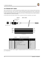
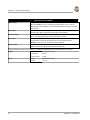
The I/O strobe lines can be accessed by inserting the 8-pin LEMO connector of the I/O strobe port cable (NovAtel p/n
01016330) into the I/O port. Figure 8 and Table 4 contain wiring and pin-out information on this cable. The other end of
the cable is provided without a connector so that the user can provide an application-specific one; the jacket insulation is
cut away slightly from the end but the insulation on each wire is intact. The Input/Output Strobes section of Appendix A
contains a specification of each I/O strobe signal.
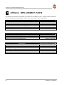
For field replacement of the LEMO connector, please consult Appendix B for the manufacturer’s part number.
Figure 8
I/O Port Cable
Red marker at top
of connector
8
7
1
2
6
3
5
4
LEMO 8-pin socket
BROWN
BLACK
RED
ORANGE
YELLOW
GREEN
BLUE
WHITE
1
2
3
4
5
6
7
8
VARF
1PPS
MKO
MKI
STATUS
GND
GND
GND
8 conductor wire
Table 4
LEMO Pin
Number
Pin 1
Pin 2
Pin 3
Pin 4
Pin 5
Pin 6
Pin 7
Pin 8
I/O Port Pin-out Description
Pin Description
VARF, variable frequency
1 PPS, one pulse per second
MSR, measure output
MKI, mark input
STATUS , valid solutions available
GND
GND
GND
Wire Color Code
Brown
Black
Red
Orange
Yellow
Green
Blue
White
Note that the STATUS line is used to toggle the valid-position LED on the front end-cap between red (power on) and
green (valid position).
10
GPStation™ User Manual