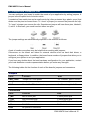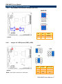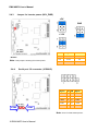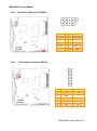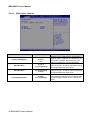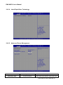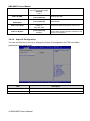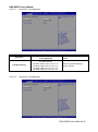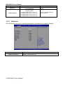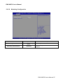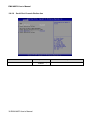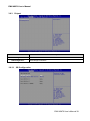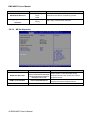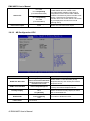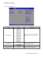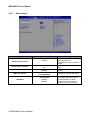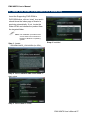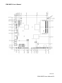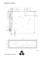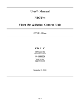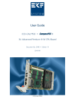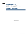
1
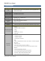
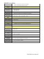
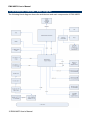
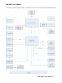
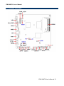
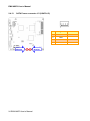
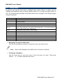
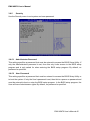
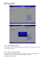
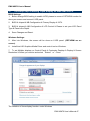
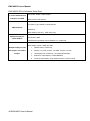
EMX-NM70 Intel® Celeron® Processor Mini ITX Motherboard with Intel® NM70 Express Chipset User’s Manual 1st Ed – 18 July 2013 Part No. E2047NM7000R EMX-NM70 User’s Manual FCC Statement THIS DEVICE COMPLIES WITH PART 15 FCC RULES. OPERATION IS SUBJECT TO THE FOLLOWING TWO CONDITIONS: (1) THIS DEVICE MAY NOT CAUSE HARMFUL INTERFERENCE. (2) THIS DEVICE MUST ACCEPT ANY INTERFERENCE RECEIVED INCLUDING INTERFERENCE THAT MAY CAUSE UNDESIRED OPERATION. THIS EQUIPMENT HAS BEEN TESTED AND FOUND TO COMPLY WITH THE LIMITS FOR A CLASS "A" DIGITAL DEVICE, PURSUANT TO PART 15 OF THE FCC RULES. THESE LIMITS ARE DESIGNED TO PROVIDE REASONABLE PROTECTION AGAINST HARMFUL INTERFERENCE WHEN THE EQUIPMENT IS OPERATED IN A COMMERCIAL ENVIRONMENT. THIS EQUIPMENT GENERATES, USES, AND CAN RADIATE RADIO FREQUENCY ENERGY AND, IF NOT INSTALLED AND USED IN ACCORDANCE WITH THE INSTRUCTION MANUAL, MAY CAUSE HARMFUL INTERFERENCE TO RADIO COMMUNICATIONS. OPERATION OF THIS EQUIPMENT IN A RESIDENTIAL AREA IS LIKELY TO CAUSE HARMFUL INTERFERENCE IN WHICH CASE THE USER WILL BE REQUIRED TO CORRECT THE INTERFERENCE AT HIS OWN EXPENSE. Copyright Notice Copyright 2013 Avalue Technology Inc., ALL RIGHTS RESERVED. No part of this document may be reproduced, copied, translated, or transmitted in any form or by any means, electronic or mechanical, for any purpose, without the prior written permission of the original manufacturer. Disclaimer Avalue Technology Inc. reserves the right to make changes, without notice, to any product, including circuits and/or software described or contained in this manual in order to improve design and/or performance. Avalue Technology assumes no responsibility or liability for the use of the described product(s), conveys no license or title under any patent, copyright, or masks work rights to these products, and makes no representations or warranties that these products are free from patent, copyright, or mask work right infringement, unless otherwise specified. Applications that are described in this manual are for illustration purposes only. Avalue Technology Inc. makes no representation or warranty that such application will be suitable for the specified use without further testing or modification. 2 EMX-NM70 User’s Manual EMX-NM70 User’s Manual Content 1. Getting Started ............................................................................................................ 5 1.1 Safety Precautions .......................................................................................... 5 1.2 Packing List .................................................................................................... 5 1.3 Document Amendment History ....................................................................... 6 1.4 Manual Objectives .......................................................................................... 7 1.5 Specifications ................................................................................................. 8 1.6 Architecture Overview—Block Diagram........................................................ 10 2. Hardware Configuration ........................................................................................... 12 2.1 Product Overview ......................................................................................... 13 2.2 Installation Procedure ................................................................................... 14 2.3 Jumper and Connector List .......................................................................... 15 2.4 Setting Jumpers & Connectors ..................................................................... 17 2.4.1 mSATA/Mini PCIe function Jumper (JS1/JS2) ...................................... 17 2.4.2 Jumper for LVDS power (PWR_LVDS) ................................................. 17 2.4.3 Jumper for inverter power (ADJ_PWR) ................................................. 18 2.4.4 Serial port 1/2 connector (JCOM1/2) ..................................................... 18 2.4.5 Front Panel Switches (FPANEL) ........................................................... 19 2.4.6 2.4.7 2.4.8 2.4.9 2.4.10 2.4.11 2.4.12 2.4.13 LCD Inverter connector (INCN1) ........................................................... 19 LVDS connector (JLVDS1).................................................................... 20 General Purpose I/O (GPIO1) ............................................................... 21 USB Connector 1 - USB2.0 (FUSB1) .................................................... 21 CIR connector (CIR) ............................................................................. 22 Speaker Headers (JSPK) ..................................................................... 22 Power connector (J1) ........................................................................... 23 SATA Power connector 1/2 (VSATA1/2) .............................................. 24 3.BIOS Setup .................................................................................................................... 25 3.1 Introduction................................................................................................... 26 3.2 Starting Setup............................................................................................... 26 3.3 3.4 3.5 3.6 Using Setup .................................................................................................. 27 Getting Help ................................................................................................. 28 In Case of Problems ..................................................................................... 28 BIOS setup ................................................................................................... 29 3.6.1 Main Menu ............................................................................................ 29 3.6.1.1 System Language .......................................................................... 29 3.6.1.2 System Date .................................................................................. 29 EMX-NM70 User’s Manual 3 EMX-NM70 User’s Manual 3.6.1.3 System Time .................................................................................. 29 3.6.2 Advanced BIOS settings ....................................................................... 30 3.6.2.1 CPU Configuration ......................................................................... 30 3.6.2.2 Onboard Device Configuration ....................................................... 31 3.6.2.3 USB Legacy Features .................................................................... 32 3.6.2.4 Inter® Rapid Start Technology ....................................................... 33 3.6.2.5 Advanced Power Management ...................................................... 33 3.6.2.6 Super IO Configuration .................................................................. 34 3.6.2.6.1 Serial Port 1 Configuration ................................................. 35 3.6.2.6.2 Serial Port 2 Configuration ................................................. 35 3.6.2.7 HW Monitor .................................................................................... 36 3.6.2.8 Watchdog Configuration ................................................................ 37 3.6.2.9 Serial Port Console Redirection ..................................................... 38 3.6.3 Chipset ..................................................................................................... 39 3.6.3.1 SB Configuration ............................................................................ 39 3.6.3.2 NB Configuration............................................................................ 40 3.6.3.2.1 LCD Control ......................................................................... 41 3.6.3.3 NB Configuration-GPU................................................................... 42 3.6.3.3.1 LCD Control-GPU ................................................................ 43 3.6.4 Boot settings ......................................................................................... 44 3.6.5 Security ................................................................................................. 45 3.6.5.1 Administrator Password ................................................................. 45 3.6.5.2 User Password............................................................................... 45 3.6.6 Save & Exit ............................................................................................ 46 3.6.6.1 Save Changes and Reset .............................................................. 46 3.6.6.2 Discard Changes and Reset .......................................................... 46 3.7 The setup step of setting Triple display on EMX-NM70-GPU ....................... 47 4. Drivers Installation....................................................................................................... 49 4.1 Install Chipset Driver .................................................................................... 50 4.2 Install VGA Driver ......................................................................................... 51 4.3 Install LAN Driver (For Realtek 8111E Gigabit Ethernet) ............................. 53 4.4 Install ME Driver ........................................................................................... 54 4.5 Install Audio Driver (For Realtek ALC661 HD Audio) ................................... 55 4.6 4.7 Install CIR Driver .......................................................................................... 56 Install VGA Driver for EMX-NM70-GPU Board only ..................................... 57 5. Mechanical Drawing .................................................................................................... 58 4 EMX-NM70 User’s Manual EMX-NM70 User’s Manual 1. Getting Started 1.1 Safety Precautions Warning! Always completely disconnect the power cord from your chassis whenever you work with the hardware. Do not make connections while the power is on. Sensitive electronic components can be damaged by sudden power surges. Only experienced electronics personnel should open the PC chassis. Caution! Always ground yourself to remove any static charge before touching the CPU card. Modern electronic devices are very sensitive to static electric charges. As a safety precaution, use a grounding wrist strap at all times. Place all electronic components in a static-dissipative surface or static-shielded bag when they are not in the chassis. Always note that improper disassembling action could cause damage to the motherboard. We suggest not removing the heatsink without correct instructions in any circumstance. If you really have to do this, please contact us for further support. 1.2 Packing List Before you begin installing your single board, please make sure that the following materials have been shipped: Quick Installation Guide X 1 Driver/Utility CD X 1 Serial ATA Signal Cable X 1 Serial ATA Power Cable X 1 IO Shield COM Cable X 1 Screw X 3 Motherboard X 1 EMX-NM70 User’s Manual 5 EMX-NM70 User’s Manual 1.3 Document Amendment History Revision Date By 1st July 2013 Avalue 6 EMX-NM70 User’s Manual Comment Initial Release EMX-NM70 User’s Manual 1.4 Manual Objectives This manual describes in details Avalue Technology EMX-NM70 Single Board. We have tried to include as much information as possible but we have not duplicated information that is provided in the standard IBM Technical References, unless it proved to be necessary to aid in the understanding of this board. We strongly recommend that you study this manual carefully before attempting to set up EMX-NM70 series or change the standard configurations. Whilst all the necessary information is available in this manual we would recommend that unless you are confident, you contact your supplier for guidance. If you have any suggestions or find any errors regarding this manual and want to inform us of these, please contact our Customer Service department with the relevant details. EMX-NM70 User’s Manual 7 EMX-NM70 User’s Manual 1.5 Specifications System CPU Intel® Celeron® Processor 1037U (2M Cache,1.80 GHz) upgradable with Celeron level Processor BIOS AMI uEFI BIOS, 64Mbit SPI Flash ROM System Chipset Intel® NM70 Express Chipset I/O Chip nuvoTon NCT6106D System Memory 1 x 204-pin DDR3 1333 SODIMMs, up to 8GB H/W Reset, 1sec. – 65535sec./min. 1sec. or 1min. step H/W Status CPU & system temperature monitoring Monitor Voltages monitoring Buzzer Buzzer onboard Expansion 1 x Mini PCI-e (Mini PCI-e and mSATA SSD is Switchable Through Jumper) 1 x RJ-45 2 x dual deck USB 2.0 connectors Rear Side External 1 x VGA I/O Connector 1 x HDMI 1 x Mic-In and 1 x Line-out 1 x DC Jack Storage: Watchdog Timer I/O - 1 x SATA III connector - 1 x SATA II connector - 2 x SATA power connectors COM: - COM1~2: support RS-232 connector, Pin 9 without / +5V&+12V supported GPIO: 8 bits Internal I/O 1 x Mini PCI-e slot Connector 2 x 5 pin, pitch 2.54mm connector for USB 2.0 2 x 1 x 3 pin, pitch 1.00mm CPU fan connector with smart fan function supported 1 x horizontal type battery connector 1 x 2 x 5 pin, pitch 2.54mm connector for front panel 1 x 2 x 2 pin ATX power connector for DC 19V input 1 x 2 x 20 pin , pitch 1.00mm connector for LVDS 1 x 5 pin , pitch 2.54mm connector for Inverter 8 EMX-NM70 User’s Manual EMX-NM70 User’s Manual 1 x 4 pin , pitch 2.54mm connector for speaker 1 x 3 pin , pitch 2.00mm connector for CIR Intel NM70 integrated HDMI:1920x1200 VGA:2048x1536 LVDS 2CH 24bits LVDS 1920x1200 Display chip Nvidia GF119 Graphics with 512MB memory (optional) With GPU : VGA + HDMI + LVDS (By Windows display setting) Without GPU : VGA + LVDS, HDMI + LVDS Chipset Realtek ALC661 HD Audio Decoding Controller Audio Interface Mic-In, Line-In Audio Amplifier Realtek ALC105 Chipset 1 x Realtek RTL8111E PCI-Express Gigabit Ethernet Ethernet Interface 10/100/1000 Gigabit Ethernet DC in +19V Single power +19V Power input / ATX mode Single power ATX Support S0,S1, S3, S4, S5 ACPI 3.0 Compliant Operating Temp. 0°C ~60°C Storage Temp. -40°C ~75°C 0%~90% relative humidity, non-condensing Size (L x W) 6.7" x 6.7" (170mm x 170mm) Weight 0.40 kg Display Chipset Resolution Multi-Display Audio Stereo Class-D 3W x 2 Ethernet Mechanical & Environmental Power Requirement Power Type ACPI Operating Humidity EMX-NM70 User’s Manual 9 EMX-NM70 User’s Manual 1.6 Architecture Overview—Block Diagram The following block diagram shows the architecture and main components of EMX-NM70. 10 EMX-NM70 User’s Manual EMX-NM70 User’s Manual The following block diagram shows the architecture and main components of EMX-NM70-GPU. EMX-NM70 User’s Manual 11 EMX-NM70 User’s Manual 2. Hardware Configuration 12 EMX-NM70 User’s Manual EMX-NM70 User’s Manual 2.1 Product Overview EMX-NM70 User’s Manual 13 EMX-NM70 User’s Manual 2.2 Installation Procedure This chapter explains you the instructions of how to setup your system. 1. Turn off the power supply. 2. Insert the DIMM module (be careful with the orientation). 3. Insert all external cables for hard disk, floppy, keyboard, mouse, USB etc. except for flat panel. A CRT monitor must be connected in order to change BIOS settings to support flat panel. 4. Connect power supply to the board via the AC/DC Adapter. 5. Turn on the power. 6. Enter the BIOS setup by pressing the delete key during boot up. Use the "Save & Exit \ Restore Defaults" feature. 7. If TFT panel display is to be utilized, make sure the panel voltage is correctly set before connecting the display cable and turning on the power. 14 EMX-NM70 User’s Manual EMX-NM70 User’s Manual 2.3 Jumper and Connector List You can configure your board to match the needs of your application by setting jumpers. A jumper is the simplest kind of electric switch. It consists of two metal pins and a small metal clip (often protected by a plastic cover) that slides over the pins to connect them. To “close” a jumper you connect the pins with the clip. To “open” a jumper you remove the clip. Sometimes a jumper will have three pins, labeled 1, 2, and 3. In this case, you would connect either two pins. The jumper settings are schematically depicted in this manual as follows: A pair of needle-nose pliers may be helpful when working with jumpers. Connectors on the board are linked to external devices such as hard disk drives, a keyboard, or floppy drives. In addition, the board has a number of jumpers that allow you to configure your system to suit your application. If you have any doubts about the best hardware configuration for your application, contact your local distributor or sales representative before you make any changes. The following tables list the function of each of the board’s jumpers and connectors. Jumpers Label Function Note PWR_LVDS Jumper for LVDS power 2 x 3 header, pitch 2.54 mm ADJ_PWR Jumper for inverter power 3 x 2 header, pitch 2.54 mm JS1/2 Msata/Mini PCIe function Jumper 3 x 2 header, pitch 2.54 mm Label Function Note F_MIC Mic-in audio jack 3.5mm phone jack F_OUT Line-out audio jack 3.5mm phone jack USB1/2 USB connector1/2 Stack USB 2.00 connector LAN RJ-45 Ethernet connector RJ45 w/ indicator connector DCIN DC power-in connector Connectors EMX-NM70 User’s Manual 15 EMX-NM70 User’s Manual CIR CIR connector 1 x 3 header, pitch 2.00 mm FPANEL Front Panel Switches 2 x 5 header, pitch 2.54 mm JLVDS1 LVDS connector 2 x 20 wafer, pitch 1.00 mm JSPK Speaker Headers 1 x 4 wafer, pitch 2.00 mm HDMI HDMI connector INCN1 LCD Inverter connector 5 x 1 header, pitch 2.54 mm SATA1/2 Serial ATA connector 1/2 SATA 7P connector VSATA1/2 SATA Power connector 1/2 1 x 4 wafer, pitch 2.50 mm JCOM1/2 Serial port 1/2 connector 2 x 5 header, pitch 2.00 mm GPIO General Purpose I/O 2 x 5 header, pitch 2.54 mm FUSB1 USB Connector 1 – USB2.0 2 x 5 header, pitch 2.54 mm VGA VGA connector D-SUB 15pin MPCIE Mini-PCIe Half size DIMM1 DDR3 SODIMM connector1 SO-DIMM 204Pin J1 Power connector 2 x 2 wafer, pitch 4.20 mm 16 EMX-NM70 User’s Manual EMX-NM70 User’s Manual 2.4 Setting Jumpers & Connectors 2.4.1 mSATA/Mini PCIe function Jumper (JS1/JS2) MINIPCIE* M-SATA JS2 JS1 * Default 2.4.2 Pin Pin Signal 1-3 2-4 M-SATA 3-5 4-6 MINIPCIE Jumper for LVDS power (PWR_LVDS) +3.3V* +12V +5V PIN Signal Max current 1-2 +3.3V 1A * Default 3-4 +5V 1A Note: This jumper is working for LVDS power. 5-6 +12V 1A EMX-NM70 User’s Manual 17 EMX-NM70 User’s Manual 2.4.3 Jumper for inverter power (ADJ_PWR) +5V* GND +3.3V PIN Signal Max current 1-2 +5V 1A 3-4 +3.3V 1A 5-6 GND * Default Note: This jumper is working for inverter power. 2.4.4 Serial port 1/2 connector (JCOM1/2) Signal JCOM2 PIN PIN Signal DCD 1 2 RXD TXD 3 4 DTR GND 5 6 DSR RTS 7 8 CTS RI 9 JCOM1 Note: Com 1/2 Pin9 without power. 18 EMX-NM70 User’s Manual EMX-NM70 User’s Manual 2.4.5 Front Panel Switches (FPANEL) Signal 2.4.6 PIN PIN Signal HD_LED+ 1 2 PWR_LED+ HD_LED- 3 4 PWR_LED- RESET 5 6 PWR_ON RESET 7 8 PWR_ON 10 GND LCD Inverter connector (INCN1) PIN Signal Max current 1 +12V 1A 2 GND 3 BLK_ON 4 Brightness 5 +5V 1A EMX-NM70 User’s Manual 19 EMX-NM70 User’s Manual 2.4.7 LVDS connector (JLVDS1) Signal Note: Mapping connector DF13-40DS-1.25C (1.0mm). 20 EMX-NM70 User’s Manual PIN PIN Signal VDDPAEA 2 1 VDDPAEA GND 4 3 GND VDDPAEA 6 5 VDDPAEA LVDS1_N0 8 7 LVDS0_N0 LVDS1_P0 10 9 LVDS0_P0 GND 12 11 GND LVDS1_N1 14 13 LVDS0_N1 LVDS1_P1 16 15 LVDS0_P1 GND 18 17 GND LVDS1_N2 20 19 LVDS0_N2 LVDS1_P2 22 21 LVDS0_P2 GND 24 23 NC LVDS1_CLKN 26 25 LVDS0_CLKN LVDS1_CLKP 28 27 LVDS0_CLKP GND 30 29 GND LVDS_DDCPDATA 32 31 LVDS_DDCPCLK GND 34 33 GND LVDS1_N3 36 35 LVDS0_N3 LVDS1_P3 38 37 LVDS0_P3 LVDS_VCON 40 39 NC EMX-NM70 User’s Manual 2.4.8 General Purpose I/O (GPIO1) Signal 2.4.9 PIN PIN Signal +3.3V 1 2 GND GPIO0 3 4 GPIO68 GPIO1 5 6 GPIO69 GPIO6 7 8 GPIO70 GPIO16 9 10 GPIO71 USB Connector 1 - USB2.0 (FUSB1) Signal PIN PIN Signal VCC 1 2 VCC DATA- 3 4 DATA- DATA+ 5 6 DATA+ GND 7 8 GND 10 GND EMX-NM70 User’s Manual 21 EMX-NM70 User’s Manual 2.4.10 2.4.11 CIR connector (CIR) PIN Signal 1 5VSB 2 GND 3 RX/TX PIN Signal 1 INTSPL+ 2 INTSPL- 3 INTSPR+ 4 INTSPR- Speaker Headers (JSPK) Note: Support 3W 4ΩX 2 speaker. Mapping connector PHR-4. 22 EMX-NM70 User’s Manual EMX-NM70 User’s Manual 2.4.12 Power connector (J1) Signal PIN PIN Signal GND 2 4 +19V GND 1 3 +19V Note: Power input +19V only. EMX-NM70 User’s Manual 23 EMX-NM70 User’s Manual 2.4.13 SATA Power connector 1/2 (VSATA1/2) VSATA2 24 EMX-NM70 User’s Manual VSATA1 PIN Signal Max current 1 12V 1A 2 GND 3 GND 4 5V 1A EMX-NM70 User’s Manual 3.BIOS Setup EMX-NM70 User’s Manual 25 EMX-NM70 User’s Manual 3.1 Introduction The BIOS setup program allows users to modify the basic system configuration. In this following chapter will describe how to access the BIOS setup program and the configuration options that may be changed. 3.2 Starting Setup The BIOS is immediately activated when you first power on the computer. The BIOS reads the system information contained in the NVRAM and begins the process of checking out the system and configuring it. When it finishes, the BIOS will seek an operating system on one of the disks and then launch and turn control over to the operating system. While the BIOS is in control, the Setup program can be activated in one of two ways: By pressing <Del> immediately after switching the system on, or By pressing the <Del> key when the following message appears briefly at the bottom of the screen during the POST (Power On Self Test). Press DEL to enter setup, F11 to popup menu If the message disappears before you respond and you still wish to enter Setup, restart the system to try again by turning it OFF then ON or pressing the "RESET" button on the system case. You may also restart by simultaneously pressing <Ctrl>, <Alt>, and <Delete> keys. If you do not press the keys at the correct time and the system does not boot, an error message will be displayed and you will again be asked to. Press DEL to enter setup, F11 to popup menu 26 EMX-NM70 User’s Manual EMX-NM70 User’s Manual 3.3 Using Setup In general, you use the arrow keys to highlight items, press <Enter> to select, use the PageUp and PageDown keys to change entries, press <F1> for help and press <Esc> to quit. The following table provides more detail about how to navigate in the Setup program using the keyboard. Button Description ↑ Move to previous item ↓ Move to next item ← Move to the item in the left hand → + key Move to the item in the right hand Main Menu -- Quit and not save changes into NVRAM Status Page Setup Menu and Option Page Setup Menu -- Exit current page and return to the pervious page or Main Menu Increase the numeric value or make changes - key Decrease the numeric value or make changes F1 key General help, only for Status Page Setup Menu and Option Page Setup Menu F7 key F8 key F9 key F10 key Previous Values Fail-Safe Values Optimized Defaults Save and Exit Esc key Navigating Through The Menu Bar Use the left and right arrow keys to choose the menu you want to be in. Note: Some of the navigation keys differ from one screen to another. To Display a Sub Menu Use the arrow keys to move the cursor to the sub menu you want. Then press <Enter>. A “” pointer marks all sub menus. EMX-NM70 User’s Manual 27 EMX-NM70 User’s Manual 3.4 Getting Help Press F1 to pop up a small help window that describes the appropriate keys to use and the possible selections for the highlighted item. To exit the Help Window press <Esc> or the F1 key again. 3.5 In Case of Problems If, after making and saving system changes with Setup, you discover that your computer no longer is able to boot, the BIOS supports an override to the NVRAM settings which resets your system to its defaults. The best advice is to only alter settings which you thoroughly understand. To this end, we strongly recommend that you avoid making any changes to the chipset defaults. These defaults have been carefully chosen by both AMI and your systems manufacturer to provide the absolute maximum performance and reliability. Even a seemingly small change to the chipset setup has the potential for causing you to use the override. 28 EMX-NM70 User’s Manual EMX-NM70 User’s Manual 3.6 BIOS setup Once you enter the BIOS Setup Utility, the Main Menu will appear on the screen. The Main Menu allows you to select from several setup functions and exit choices. Use the arrow keys to select among the items and press <Enter> to accept and enter the sub-menu. 3.6.1 Main Menu This section allows you to record some basic hardware configurations in your computer and set the system clock. 3.6.1.1 System Language Use this option to select system language 3.6.1.2 System Date Use the system date option to set the system date. Manually enter the day, month and year. 3.6.1.3 System Time Use the system time option to set the system time. Manually enter the hours, minutes and seconds. Note: BIOS setup screens shown in this chapter are for reference only, and may not exactly match what you see on your screen. Visit the Avalue website (www.avalue.com.tw) to download the latest product and BIOS information. EMX-NM70 User’s Manual 29 EMX-NM70 User’s Manual 3.6.2 Advanced BIOS settings This section allows you to configure your CPU and other system devices for basic operation through the following sub-menus. 3.6.2.1 CPU Configuration Use the CPU configuration menu to view detailed CPU specification and configure the CPU. 30 EMX-NM70 User’s Manual EMX-NM70 User’s Manual 3.6.2.2 Onboard Device Configuration Item Onboard Lan Control Lan Pxe OpROM Control Storage OpROM Control Onboard Audio Control Internal HDMI Audio Control Mini Pcie Control (Port4) USB Control Options Disabled Enabled[Default] Disabled[Default] Enabled Disabled Enabled[Default] Disabled Enabled[Default] Disabled[Default] Enabled Disabled Enabled[Default] Disabled Enabled[Default] Description Enable or disable Onboard NIC. Controls the execution of PXE OpROM. Controls the execution of Storage OpROM. Control Detection of the Azalia device. Disabled = Azalia will be unconditionally disabled Enabled = Azalia will be unconditionally enabled Auto = Azalia will be enabled if present, disabled otherwise. Enable or disable internal HDMI codec for Azalia. Enable or disable the Mini Pcie Port. Enable or disable the USB Port. EMX-NM70 User’s Manual 31 EMX-NM70 User’s Manual 3.6.2.3 USB Legacy Features Item Options Legacy USB Support Enabled[Default] Disabled Auto XHCI Hand-off Disabled Enabled[Default] EHCI Hand-off Disabled[Default] Enabled Port 60/64 Emulation Disabled Enabled[Default] 32 EMX-NM70 User’s Manual Description Enables Legacy USB support, AUTO option disables legacy support if no USB devices are connected. DISABLE option will keep USB devices available only for EFI applications. This is a workaround for OSes without XHCI hand-off support. The XHCI ownership change should be claimed by XHCI driver. This is a workaround for OSes without EHCI hand-off support. The EHCI ownership change should be claimed by EHCI driver. Enables I/O port 60h/64h emulation support. This should be enabled for the complete USB keyboard legacy support for non-USB aware OSes. EMX-NM70 User’s Manual 3.6.2.4 Inter® Rapid Start Technology 3.6.2.5 Advanced Power Management Item Options ACPI Sleep State Suspend Disabled Description Select ACPI sleep state the system will enter EMX-NM70 User’s Manual 33 EMX-NM70 User’s Manual Wake By PME S1 only(CPU Stop Clock) S3 only(Suspend to RAM) [Default] Auto Disabled Enabled[Default] USB Keyboard/Mouse when the SUSPEND button is pressed. Wakeup By PME. Disabled Enabled[Default] Enabled/Disabled Wakeup From S3/S4 By USB KB/MS. Power-Loss State Always off[Default] Always on Keep last state Control the status when Power loss occurs. Poweron By RTC Disabled[Default] Enabled S3/S4 Wake Enable or disable System wake on alarm event. When enabled, System will wake on the hr::min::sec specified. 3.6.2.6 Super IO Configuration You can use this item to set up or change the Super IO configuration for FDD controllers, parallel ports and serial ports. Item Description Serial Port 1 Configuration Set Parameters of Serial Port 1 (COMA). Serial Port 2 Configuration Set Parameters of Serial Port 2 (COMB). 34 EMX-NM70 User’s Manual EMX-NM70 User’s Manual 3.6.2.6.1 Serial Port 1 Configuration Item Serial Port Change Settings 3.6.2.6.2 Option Disabled Enabled[Default] Auto[Default] IO=3F8h; IRQ=4; IO=3F8h; IRQ=3,4,5,6,7,,10,11,12; IO=2F8h; IRQ=3,4,5,6,7,10,11,12; IO=3E8h; IRQ=3,4,5,6,7,10,11,12; IO=2E8h; IRQ=3,4,5,6,7,10,11,12; Description Enable or Disable Serial Port (COM). Select an optimal setting for Super IO device. Serial Port 2 Configuration EMX-NM70 User’s Manual 35 EMX-NM70 User’s Manual Item Serial Port Change Settings Option Disabled Enabled[Default] Auto[Default] IO=2F8h; IRQ=3; IO=3F8h; IRQ=3,4,5,6,7,10,11,12; IO=2F8h; IRQ=3,4,5,6,7,10,11,12; IO=3E8h; IRQ=3,4,5,6,7,10,11,12; IO=2E8h; IRQ=3,4,5,6,7,10,11,12; Description Enable or Disable Serial Port (COM). Select an optimal setting for Super IO device. 3.6.2.7 HW Monitor The H/W Monitor shows the operating temperature, fan speeds and system voltages. Item Smart Fan Function Description Enable or Disable Smart Fan. 36 EMX-NM70 User’s Manual EMX-NM70 User’s Manual 3.6.2.8 Watchdog Configuration Item Options Watchdog Count Mode Second[Default] Minute Watchdog TimeOut Value 0[Default] Description WatchDog Count Mode Selection. Fill WatchDog TimeOut Value, 0 means disabled. EMX-NM70 User’s Manual 37 EMX-NM70 User’s Manual 3.6.2.9 Serial Port Console Redirection Item Options Console Redirection Disabled[Default] Enabled 38 EMX-NM70 User’s Manual Description Console Redirection Enable or Disable. EMX-NM70 User’s Manual 3.6.3 Chipset Item Description SB Configuration PCH Parameters. NB Configuration North Bridge Parameters. 3.6.3.1 SB Configuration EMX-NM70 User’s Manual 39 EMX-NM70 User’s Manual Item Options SATA Mode Selection IDE[Default] AHCI RAID IDE Legacy / Native Mode Native[Default] Legacy Selection Description Determines how SATA controller(s) operate. IDE Legacy / Native Mode Selection. 3.6.3.2 NB Configuration Item Options DVMT Pre-Allocated 32M/64M[Default]/96M/128M/ 160M/192M/224M/256M/288M /320M/352M/384M/416M/448 M/480M/512M/1024M DVMT Total Gfx Mem 128M/256M[Default]/MAX LCD Control LCD Control. 40 EMX-NM70 User’s Manual Description Select DVMT 5.0 Pre-Allocated (Fixed) Graphics Memory size used by the Internal Graphics Device. Select DVMT 5.0 Total Graphics Memory size used by the Internal Graphics Device. EMX-NM70 User’s Manual 3.6.3.2.1 LCD Control Item Options Primary IGFX Boot Display VBIOS Default[Default] CRT EFP LFP LCD Panel Type Panel Scaling Backlight Control VBIOS Default[Default] 640x480 18/1 800x600 18/1 1024x768 18/1 1280x1024 24/2 1024x600 18/1 800x480 18/1 1600x1200 24/2 1366x768 24/1 1680x1050 24/2 1920x1200 24/2 1440x900 24/2 1600x900 24/2 1024x768 24/1 1280x800 18/1 1920x1080 24/2 2048x1536 24/2 Auto[Default] Off Force Scaling PWM Inverted[Default] PWM Normal Description Select the Video Device which will be activated during POST. This has no effect if external graphics present. Secondary boot display selection will appear based on your selection. VGA modes will be supported only on primary display. Select LCD panel used by Internal Graphics Device by selecting the appropriate setup item. Select the LCD panel scaling option used by the Internal Graphics Device. Back Light Control Setting. EMX-NM70 User’s Manual 41 EMX-NM70 User’s Manual No LVDS Int-LVDS[Default] (For EMX-NM70-GPU) Active LFP No LVDS[Default] Int-LVDS (For EMX-NM70) 18 Bit[Default] 24 Bit Panel Color Depth Select the Active LFP Configuration. No LVDS:VBIOS does not enable LVDS. Int-LVDS:VBIOS enables LVDS drive by Integrated encoder. SDVO LVDS: VBIOS enables LVDS driver by SDVO encoder. eDP Port-A: LFP Driven by Int-Display Port encoder from Port-A. eDP Port-D: LFP Driven by Int-DisplayPort encoder from Port-D (through PCH). Select the LFP Panel Color Depth. 3.6.3.3 NB Configuration-GPU Item Options DVMT Pre-Allocated 32M/64M[Default]/96M/128M/ 160M/192M/224M/256M/288M /320M/352M/384M/416M/448 M/480M/512M/1024M DVMT Total Gfx Mem 128M/256M[Default]/MAX Auto IGFX PEG[Default] Disabled Enabled[Default] Auto Primary Display Enable PEG LCD Control LCD Control. 42 EMX-NM70 User’s Manual Description Select DVMT 5.0 Pre-Allocated (Fixed) Graphics Memory size used by the Internal Graphics Device. Select DVMT 5.0 Total Graphics Memory size used by the Internal Graphics Device. Select which of IGFX/PEG/PCI Graphics device should be Primary Display Or select SG for Switchable Gfx. To enable or disable the PEG. EMX-NM70 User’s Manual 3.6.3.3.1 LCD Control-GPU Item LCD Panel Type Panel Scaling Backlight Control Panel Color Depth Options VBIOS Default[Default] 640x480 18/1 800x600 18/1 1024x768 18/1 1280x1024 24/2 1024x600 18/1 800x480 18/1 1600x1200 24/2 1366x768 24/1 1680x1050 24/2 1920x1200 24/2 1440x900 24/2 1600x900 24/2 1024x768 24/1 1280x800 18/1 1920x1080 24/2 2048x1536 24/2 Auto[Default] Off Force Scaling PWM Inverted[Default] PWM Normal 18 Bit[Default] 24 Bit Description Select LCD panel used by Internal Graphics Device by selecting the appropriate setup item. Select the LCD panel scaling option used by the Internal Graphics Device. Back Light Control Setting. Select the LFP Panel Color Depth. EMX-NM70 User’s Manual 43 EMX-NM70 User’s Manual 3.6.4 Boot settings Item Setup Prompt Timeout Bootup NumLock State Full Logo Screen ME Flash Protect Option 1~65535 On[Default] Off Disabled[Default] Enabled Disabled Enabled[Default] Description Number of seconds to wait for setup activation key. 65535(0xFFFF) means indefinite waiting. Select the keyboard NumLock state. Enables or disables Full Logo Screen. Disabled it for update ME region. st UEFI Boot 44 EMX-NM70 User’s Manual Auto[Default] Enabled Disabled Auto: If the 1 boot HDD is GPT then enable UEFI boot options, otherwise disable. Enabled: Enable all UEFI boot options. Disabled all UEFI boot options. EMX-NM70 User’s Manual 3.6.5 Security Use the Security menu to set system and user password. 3.6.5.1 Administrator Password This setting specifies a password that must be entered to access the BIOS Setup Utility. If only the Administrator's password is set, then this only limits access to the BIOS setup program and is only asked for when entering the BIOS setup program. By default, no password is specified. 3.6.5.2 User Password This setting specifies a password that must be entered to access the BIOS Setup Utility or to boot the system. If only the User's password is set, then this is a power on password and must be entered to boot or enter the BIOS setup program. In the BIOS setup program, the User will have Administrator rights. By default, no password is specified. EMX-NM70 User’s Manual 45 EMX-NM70 User’s Manual 3.6.6 Save & Exit 3.6.6.1 Save Changes and Reset Any changes made to BIOS settings are stored in NVRAM. The setup program then exits and reboots the controller. 3.6.6.2 Discard Changes and Reset Any changes made to BIOS settings during this session of the BIOS setup program are discarded. The setup program then exits and reboots the controller. 46 EMX-NM70 User’s Manual EMX-NM70 User’s Manual 3.7 The setup step of setting Triple display on EMX-NM70-GPU BIOS Settings: 1. Before change BIOS setting to enable LVDS, please to connect CRT/HDMI monitor for show your screen and connect LVDS panel. 2. BIOS chipset NB Configuration Primary Display IGFX. 3. BIOS chipset NB Configuration LCD Control Please to set your LCD Panel Type & Panel color Depth. 4. Save Changes and Reset. Windows Settings: 5. After into Windows, the screen will be show on LVDS panel. (CRT/HDMI are no screen). 6. Install Intel HD Graphics Media Driver and control tool on Windows. 7. To set Multiple displays on Control Panel Customize Desktop Display Screen Resolution Select you monitor and select“Extend”or”Clone”. The limitation of three display function under Windows EMX-NM70 User’s Manual 47 EMX-NM70 User’s Manual EMX-NM70-GPU at Windows Setup Step. To choice different kind of Graphic on BIOS PEGCRT, HDMI: nVidia Graphic. IGFXLVDS: Intel Chipset Boot Display: VBIOS DefaultCRT+HDMI LCD Panel Type: Default is 1024x768 18/1 VBIOS Default BIOS/DOS: IGFX+PEGLVDS only , PEGCRT only Multiple Display for nVidai Graphic Windows: PEGCRT+HDMI Clone/Extend: By Display tool of Windows 7 or nVidia tool. Windows: IGFX+PEG LVDS + HDMI and CRT Multiple Display for Intel 1. Default value is LVDS only. HD Graphic with nVidia 2. Monitor 1 is LVDS, monitor 2 is HDMI, monitor 3 is CRT. Graphic 3. Use Display tool of Windows 7 to modify Multi-Display. 4. Extend for Triple Display: LVDS/HDMI/CRT 5. Clone for Dual Display: Only HDMI and CRT. LVDS is extend. 48 EMX-NM70 User’s Manual EMX-NM70 User’s Manual 4. Drivers Installation Note: Installation procedures and screen shots in this section are for your reference and may not be exactly the same as shown on your screen. EMX-NM70 User’s Manual 49 EMX-NM70 User’s Manual 4.1 Install Chipset Driver Insert the Supporting DVD-ROM to DVD-ROM drive, click on “start” icon and it should show the index page of Avalue’s products automatically. If not, locate the folder HTML and choose the product from the targeted folder. Note: The installation procedures and screen shots in this section are based on Windows 7 operating system. Step 1. Locate 「\Driver_Chipset\Intel\EMX-NM70_Chipset」. Step 4. Select Next to continue installation. Step 2. Select Next to start setup. Step 5. Select Next to continue installation. Step 3. Select Yes to the next step. Step 6. Select Finish to complete Installation. 50 EMX-NM70 User’s Manual EMX-NM70 User’s Manual 4.2 Install VGA Driver Insert the Supporting DVD-ROM to DVD-ROM drive, click on “start” icon and it should show the index page of Avalue’s products automatically. If not, locate the folder HTML and choose the product from the targeted folder. Note: The installation procedures and screen shots in this section are based on Windows 7 operating system. Step 1. Locate 「\VGA\EMX-NM70_VGA\Intel Graphics」. Step 4. Select YES to continue installation. Step 2. Select Next to start setup. Step 5. Select Next to continue installation. Step 3. Select Next to the next step. Step 6. Select Next to continue installation. EMX-NM70 User’s Manual 51 EMX-NM70 User’s Manual Step 7. Select Finish to complete Installation. 52 EMX-NM70 User’s Manual EMX-NM70 User’s Manual 4.3 Install LAN Driver (For Realtek 8111E Gigabit Ethernet) Insert the Supporting DVD-ROM to DVD-ROM drive, and it should show the index page of Avalue’s products automatically. If not, locate Index.htm and choose the product from the menu left, or link to \Driver_Gigabit\Realtek\RTL8111E\EMX-N M70_LAN. Note: The installation procedures and screen shots in this section are based on Windows 7 operation system. Step 3. Click Finish to complete setup. Step 1. Click Next to Install. Step 2. Click Install to begin the installation. EMX-NM70 User’s Manual 53 EMX-NM70 User’s Manual 4.4 Install ME Driver Insert the Supporting DVD-ROM to DVD-ROM drive, click on “start” icon and it should show the index page of Avalue’s products automatically. If not, locate the folder HTML and choose the product from the targeted folder. Note: The installation procedures and screen shots in this section are based on Windows 7 operating system. Step 1. Locate 「\Utility\EMX-NM70_ME」. Step 2. Select Next to start setup. Step 3. Select Yes to the next step. 54 EMX-NM70 User’s Manual Step 4. Select Next to continue installation. Step 5. Select Finish to complete installation EMX-NM70 User’s Manual 4.5 Install Audio Driver (For Realtek ALC661 HD Audio) Insert the Supporting DVD-ROM to DVD-ROM drive, and it should show the index page of Avalue’s products automatically. If not, locate Index.htm and choose the product from the menu left, or link to \Driver_Audio\EMX-NM70_Audio. Note: The installation procedures and screen shots in this section are based on Windows 7 operation system. If the warning message appears while the installation process, click Continue to go on. Step1. Click Next to Install.. Step 2. Select Finish to complete Installation. EMX-NM70 User’s Manual 55 EMX-NM70 User’s Manual 4.6 Install CIR Driver Insert the Supporting DVD-ROM to DVD-ROM drive, and it should show the index page of Avalue’s products automatically. If not, locate Index.htm and choose the product from the menu left, or link to \Utility\EMX-NM70_CIR. Note: The installation procedures and screen shots in this section are based on Windows 7 operation system. Step 3. Click Finish to complete setup. Step 1. Click Next to Install. Step 2. Click Install to begin the installation. 56 EMX-NM70 User’s Manual EMX-NM70 User’s Manual 4.7 Install VGA Driver for EMX-NM70-GPU Board only Insert the Supporting DVD-ROM to DVD-ROM drive, click on “start” icon and it should show the index page of Avalue’s products automatically. If not, locate the folder HTML and choose the product from the targeted folder. Note: The installation procedures and screen shots in this section are based on Windows 7 operating system. Step 1. Locate 「\VGA\EMX-NM70_VGA\NVIDA (for GPU)」. Step 4. Installed. Step 2. Select AGREE AND CONTINUE to start setup. Step 3. Select Next to Install. EMX-NM70 User’s Manual 57 EMX-NM70 User’s Manual 5. Mechanical Drawing 58 EMX-NM70 User’s Manual EMX-NM70 User’s Manual Unit: mm EMX-NM70 User’s Manual 59 EMX-NM70 User’s Manual Unit: mm 60 EMX-NM70 User’s Manual