1
I-8094 and I-8094F Getting Started
Manual
(Version 2.4)
Hardware & Software & Application
Using I-8094/I-8094F PAC Motion Control Module
http:/www.icpdas.com
1
i8094_Getting_Started_V2.4
Warranty
All products manufactured by ICPDAS Inc. are warranted against defective
materials for a period of one year from the date of delivery to the original
purchaser.
Warning
ICPDAS Inc. assumes no liability for damages consequent to the use of this
product. ICPDAS Inc. reserves the right to change this manual at any time without
notice. The information furnished by ICPDAS Inc. is believed to be accurate and
reliable. However, no responsibility is assumed by ICPDAS Inc. for its use, or for
any infringements of patents or other rights of third parties resulting from its use.
Copyright
Copyright 1997-2005 by ICPDAS Inc., LTD. All rights reserved worldwide.
Trademark
The names used for identification only maybe registered trademarks of their
respective companies.
License
The user can use, modify and backup this software on a single machine. The
user may not reproduce, transfer or distribute this software, or any copy, in whole
or in part.
http:/www.icpdas.com
2
i8094_Getting_Started_V2.4
Contents of I8094/I8094F
1 INTRODUCTION............................................................... 7
1.1 Introduction ................................................................................................7
1.2 Hardware Specification .............................................................................8
1.2.1 Main Specification..................................................................................... 8
1.2.2 Interpolation Function ............................................................................... 8
1.2.3 Pulse Output............................................................................................. 9
1.2.4 Encoder Input ........................................................................................... 9
1.2.5 Position counter ...................................................................................... 10
1.2.6 Auto-Homing ........................................................................................... 10
1.2.7 Servo Motor Input Signal ........................................................................ 10
1.2.8 Limit Switch Input Signal......................................................................... 10
1.2.9 Other Input Signals ................................................................................. 11
1.2.10 Emergency Stop Signal Input ............................................................... 11
1.2.11 General Output Signal .......................................................................... 11
1.2.12 Integral Input Signal Filters ................................................................... 11
1.2.13 Software Limit ....................................................................................... 11
1.2.14 Manual Pulse Generator....................................................................... 11
1.2.15 LED for Module status .......................................................................... 12
1.2.16 FRnet (i8094F only) .............................................................................. 12
1.3 Environment .............................................................................................12
1.4 Ordering Information ..............................................................................13
2 HARDWARE INSTALLATION...................................... 14
2.1 Checking Package and Installation ........................................................14
2.1.1 Checking package .................................................................................. 14
2.1.2 Installation .............................................................................................. 14
2.2 DN-8468G Terminal Board......................................................................17
2.2.1 Board Layout for DN-8468G ................................................................... 17
2.2.2 Signal Connections for DN-8468G.......................................................... 18
2.2.3 Jumper and Switch Settings ................................................................... 24
2.3 Input/Output Connections.......................................................................26
2.3.1 Pulse output signals................................................................................ 26
2.3.2 Connection for Limit switch Signal .......................................................... 27
2.3.3 General Purpose Input Signals(nINPOS,nALARM) ................................ 28
http:/www.icpdas.com
3
i8094_Getting_Started_V2.4
2.3.4 Encoder Signals ..................................................................................... 28
2.3.5 Emergency Stop Signal .......................................................................... 29
2.3.6 Manual Pulse Generator Input Signal (EXP+,EXP-) ............................... 29
2.3.7 General Purpose Output signals(Servo On/Off)...................................... 30
2.4 Connection Example for Motor Driver ..................................................31
3 SOFTWARE DEVELOPMENT OVERVIEW .............. 32
3.1 Software development Overview ............................................................32
3.1.1 Register Module ..................................................................................... 33
3.2 Safety IO Setting.......................................................................................33
3.2.1 Emergency Stop Signal Input ................................................................. 33
3.2.2 Configure the Servo ALARM Signals ...................................................... 33
3.2.3 Configure the Limit Switch Signals(±EL)................................................. 34
3.2.4 Configure the Software Limite(±SEL) ..................................................... 34
3.3 Error Checking .........................................................................................34
3.4 Basic Configuration of Motion................................................................35
3.5 Manual Pulse Generator Testing ............................................................35
3.6 Home Search .............................................................................................37
3.6.1 Home Search Configuration ................................................................... 37
3.6.2 Running the Home Search ..................................................................... 38
3.7 Basic Motion .............................................................................................39
3.7.1 Speed Profie of the Motion Control ......................................................... 39
3.7.2 Basic Setting of Single Axis .................................................................... 40
3.7.3 Basic Motion of Single Axis..................................................................... 41
3.7.4 Basic Setting of Muti-Axes Interpolation ................................................. 41
3.7.5 Basic Motion of Muti-Axes Interpolation.................................................. 42
3.8 Advance Motion........................................................................................43
3.9 Synchronization Action............................................................................43
4 GETTING STARTED OF SOFTWARE......................... 44
4.1 WinCon eVC++ Guideline.......................................................................44
4.1.1 Confirm the Relative Files....................................................................... 44
4.1.2 Create a new eVC++ Application Project................................................ 44
4.1.3 Add the I8094.h into eVC++ Application Project ..................................... 46
4.1.4 Add the Reference Path into eVC++ Application Project ........................ 47
4.1.5 Start the eVC++ Sample ......................................................................... 48
4.1.6 Build the Project ..................................................................................... 51
http:/www.icpdas.com
4
i8094_Getting_Started_V2.4
4.1.7 Download and Run ................................................................................. 52
4.2 Microsoft Visual Studio .NET 2003(VB.NET,C#) Guideline ............53
4.2.1 Confirm the Relative Files....................................................................... 53
4.2.2 Create a new VB.NET/C# Application Project ........................................ 53
4.2.3 Add the DLL into Application Project....................................................... 55
4.2.4 Start the VB.NET/C# Sample.................................................................. 57
4.2.5 Build the Project ..................................................................................... 59
4.2.6 Download and Run ................................................................................. 59
4.3 I-8000 Turbo C Guideine .........................................................................60
4.3.1 Confirm the Relative Files....................................................................... 60
4.3.2 Create a new TC ++ Application Project ................................................. 60
4.3.3 Start the TC Sample ............................................................................... 62
4.3.4 Build the Project ..................................................................................... 68
4.3.6 Download and Run ................................................................................. 68
APPENDIX-A SETUP TOOLS & OTHERS..................... 70
A.1 Setup the Development Environment of I8094.....................................70
A.1.1 eVC ++ 4.0 ............................................................................................. 70
A.1.2 Visual Studio .NET 2003(VB.NET,C#) ................................................. 70
A.1.3 Turbo C .................................................................................................. 70
A.2 I8094 Surface ...........................................................................................71
A.3 Dimensions ...............................................................................................72
A.4 The Version Upgrades Note ....................................................................73
APPENDIX-B OTHERS TERMINAL BOARDS............. 74
B.1 DN-8468M Daughter Board....................................................................74
B.1.1 Board Layout for DN-8468M .................................................................. 74
B.1.2 Signal Connections for DN-8468M ......................................................... 75
B.1.3 Jumper and Switch Settings................................................................... 81
B.2 DN-8468P Daughter Board .....................................................................83
B.2.1 Board Layout for DN-8468P ................................................................... 83
B.2.2 Signal Connections for DN-8468P.......................................................... 84
B.2.3 Jumper and Switch Settings................................................................... 89
B.3 DN-8486Y Daughter Board.....................................................................91
B.3.1 Board Layout for DN-8468Y ................................................................... 91
B.3.2 Signal Connections for DN-8468Y.......................................................... 92
http:/www.icpdas.com
5
i8094_Getting_Started_V2.4
B.3.3 Jumper and Switch Settings................................................................... 97
B.4 DN-8468D Daughter Board ....................................................................99
B.4.1 Board Layout for DN-8468D................................................................... 99
B.4.2 Signal Connections for DN-8468D ....................................................... 100
B.4.3 Jumper and Switch Settings................................................................. 108
B.5 DN-8468FB Daughter Board ................................................................ 111
B.5.1 Board Layout for DN-8468FB................................................................111
B.5.2 Signal Connections for DN-8468FB ..................................................... 112
B.5.3 Jumper and Switch Settings................................................................. 120
http:/www.icpdas.com
6
i8094_Getting_Started_V2.4
1 INTRODUCTION
1.1 Introduction
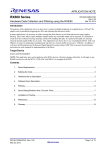
The I-8094 and I-8094F are the 4-axes pulse-type stepping/servo motor motion
control module that can be used on any of the ICPDAS I-8000 and WinCon series
controllers, and is suitable for general-purpose motion application. These modules
contain a high-performance motion ASIC. Apart from a wide speed range, these
intelligent motion controllers have a variety of motion control functions built in, such as
2~3-axes
linear
interpolation,
2-axes
circular
interpolation,
T/S-curve
acceleration/deceleration, various synchronous actions, automatic homing, and others.
Besides, it is a module that has full functions of I-8094F plus one port of FRnet. The
FRnet port allows this module to expand its fast remote I/O easily. This two-wired FRnet
can automatically scan its 128 DI and 128 DO with a period of 0.72/2.88ms. In addition,
most of the I-8094 and I-8094F motion control functions are performed with little load on
the processor. While driving the motors, the motion status, and the other I/O status on
the I-8000 or WinCon controllers, can still be monitored. As a result of the low CPU
loading requirements of I-8094 and I-8094F, one or more motion modules may be used
on a single I-8000 or WinCon controllers. ICPDAS also has provided a wide range of
functions and examples to reduce the need for programming by user, making it a highly
cost-effective solution for machine makers.
I8094 with PAC controller (WinCon-8000 and I-8000)
http:/www.icpdas.com
7
i8094_Getting_Started_V2.4
1.2 Hardware Specification
1.2.1 Main Specification
ASIC Chip
Number of controllable
Up to 4M PPS pulse output
MCX314As
4-Axes, Pulse output (stepping & servo
motor)
1.2.2 Interpolation Function
2-axes & 3-axes linear interpolation
Interpolation range
Vectors speed of interpolation
Precision of interpolation
−2,147,483,646 ~ +2,147,483,646
1 PPS ~ 4M PPS
± 0.5 LSB
Circular interpolation
Interpolation range
Vectors Speed of interpolation
−2,147,483,646 ~ +2,147,483,646
1 PPS ~ 4M PPS
Relative interpolation function
Any 2-axes or 3-axes interpolation
Fixed vectors speed
Continuous interpolation
http:/www.icpdas.com
8
i8094_Getting_Started_V2.4
1.2.3 Pulse Output
Output speed range
Output precision
Jerk range of S-curve
Acceleration/deceleration range
Speed precision
Output numbers
Velocity profiles mode:
Fixed
Symmetrical & Asymmetrical Trapezoidal velocity profile
Symmetrical & Asymmetrical S-curve velocity profile
Acceleration & Deceleration mode
Auto
By user define
1 PPS ~ 4 MPPS
± 0.1%
954 ~ 62.5 x 10^6 PPS/S^2
477 x 10^3 ~ 31.25 x 10^9 PPS/S^2
125 ~ 1 x 10^6 PPS/S
62.5×10^3 ~ 500 x 10^6 PPS/S
1 PPS ~ 500PPS( Depend on the
max.speed)
0 ~ 4,294,967,295 / unlimited
Position & Speed change on the fly
Fixed pulse output by Trapezoidal and S-curve velocity profile
Pulse output option: CW/CCW, PULSE/DIR
Programmable logic level (Rising Edge/ Falling Edge)
1.2.4 Encoder Input
Encoder option: A/B phase, Up/Down
Programmable A/B phase mode: 1, 1/2, and 1/4 A/B phase
http:/www.icpdas.com
9
i8094_Getting_Started_V2.4
1.2.5 Position counter
Command counter range
−2,147,483,648 ~ +2,147,483,647
Encoder counter range
−2,147,483,648 ~ +2,147,483,647
Programmable ring counter
Programmable direction of counter
Using DI(IN3) to Clear feedback counter
Programmable read & write counter
1.2.6 Auto-Homing
Four Steps
Step 1 ( High-speed ”Near Home” searching)
Step 2 ( Low-speed ”Home” searching)
Step 3 ( Low-speed Index Z searching)
Step 4 ( High-speed offset drive)
Even though there are only 4 steps of the home searching, but user can vary
the operations into over 10 homing modes by software function since its
configurable action and direction of each step.
1.2.7 Servo Motor Input Signal
Alarm
Choose IN2: In Position or Servo Ready signal
Choose input signal: Enable/Disable and logical level.
1.2.8 Limit Switch Input Signal
Two-limit switch signal for each axis: +Limit, −Limit
Programmable logic level
Programmable action mode( slow-down stop or immediately stop)
http:/www.icpdas.com
10
i8094_Getting_Started_V2.4
1.2.9 Other Input Signals
IN3 : other purpose, as a trigger of synchronal control……
1.2.10 Emergency Stop Signal Input
There is a Emergency stop signal for Each module.
1.2.11 General Output Signal
The Servo-on signal (nOUT1) can be used as servo-on control or general
purpose output signal for each axis.
1.2.12 Integral Input Signal Filters
The motion module is equipped with an integral type filter in the input step of
each input signal. User can be selected a filter time constant.
1.2.13 Software Limit
There are two software-limit for each axis: -SLimit & + SLimit ( Setting range :
−2,147,483,646 ~ +2,147,483,646)
1.2.14 Manual Pulse Generator
Fixed Pulse Driving Mode (CW/CCW pulse mode)
Continuous Pulse Driving Mode (CW/CCW pulse mode)
Manual pulsar mode(A/B phase pulse mode)
Disable Mode: Disable manual pulse function
http:/www.icpdas.com
11
i8094_Getting_Started_V2.4
1.2.15 LED for Module status
Red LED Æ Power light
Orange LED Æ Servo Alarm
Ex:Misuibishi driver, No Alm: turn Orange LED on
Green LED Æ during Running Motion
1.2.16 FRnet (i8094F only)
Connect to the distributed DI/DO module
DI Æ max up to 128
DO Æ max up to 128
Read the status of distributed DI
Control the status of distributed DO
Support interrupt and frequence division function
Reset function
1.3 Environment
Operating Temp:
Storage Temp:
Operating Humidity:
Storage Humidity:
I/O optically isolated
2500Vrms
External Power supply( Input): 24V DC (connect to terminal board)
http:/www.icpdas.com
-20 ~ + 75°C
-30 ~ +85°C
10 ~ 85%,non-condensing
5 ~ 90%,non-condensing
12
i8094_Getting_Started_V2.4
1.4 Ordering Information
I-8000、W-8000 PAC controllers
i8094
DN-8468GB
DN-8468MB
DN-8468PB
DN-8468DB
CA-SCSI15
http:/www.icpdas.com
4-axes motion control module
For general purpose usage
For Mitsubishi Servo motor
For Panasonic servo motor
For Detal servo motor
68-pin SCSI-II cable,length:1.5 m
13
i8094_Getting_Started_V2.4
2 HARDWARE INSTALLATION
2.1 Checking Package and Installation
2.1.1 Checking package
The i8094 and i8094F are a 4-axes stepping/servo motor control module that can
be used on any of the ICPDAS I-8000 and WinCon series controllers. The base system
package is as below list:
I-8000、W-8000 Embedded PAC control system series(Two systems choose
one)
i8094/i8094F-G/S includes the following item
i8094/i8094F
4-axes motion module
DN-8468
Terminal board for i8094 and i8094F
CA-SCSI15
68-pin SCSI-II cable,length:1.5 m
2.1.2 Installation
Prepare controller
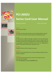
1. Choose a PAC controller of ICPDAS (I-8000 or W-8000series) and have empty
slot.
2. Turn power off
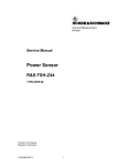
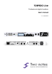
Module Plug in controller and wiring
1. Plug in the i8094/i8094F into a empty slot of I-8000/W-8000.
2. Connect the i8094/i8094F with DN-8468G by a CA-SCSI15 cable, as the below
figure:
http:/www.icpdas.com
14
i8094_Getting_Started_V2.4
http:/www.icpdas.com
15
i8094_Getting_Started_V2.4
Figure. i8094 with PAC controller (WinCon-8000 and I-8000)
http:/www.icpdas.com
16
i8094_Getting_Started_V2.4
2.2 DN-8468G Terminal Board
The DN-8468 is the terminal board for general purpose amplifier usage. It has 4-axis I/O signals.
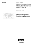
2.2.1 Board Layout for DN-8468G
107mm
JP8
JP11
JP9
JP10
Z
CON4
JP7
CON3
JP5 JP6
X
162mm
RJ1
Y
U
JP13
JP15
JP12
JP14
CON5
EMG
SW
CON1
68 PIN SCSI
CON2
CON6
DN-8468G
TB2
Fig. 2.0
http:/www.icpdas.com
Board layout for the DN-8468G
17
i8094_Getting_Started_V2.4
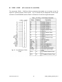
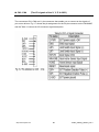
2.2.2 Signal Connections for DN-8468G
Maintaining signal connections is one of the most important factors in ensuring that your
application system is sending and receiving data correctly.
Pin Assignment for CON1
The I/O connector on the DN-8468G is a 68-pin SCSI II connector that enables you to connect to
the I8094/I8094F motion modue. Fig. 2.1 shows the pin assignment for the 68-pin I/O connector
on the DN-8468G (or on the PISO-PS400), and refer to Table 2.1, 2.2 for description of each
motion I/O signal.
Fig. 2.1 I/O connector pin assignment for the CON1
http:/www.icpdas.com
18
i8094_Getting_Started_V2.4
Table 2.1 DN-8468G I/O connector signal description (part 1)
Pin name
XECA
YECA
ZECA
UECA
XECB
YECB
ZECB
UECB
XINPOS
YINPOS
ZINPOS
UINPOS
XALARM
YALARM
ZALARM
UALARM
XLMTP
YLMTP
ZLMTP
ULMTP
XLMTM
YLMTM
ZLMTM
ULMTM
XIN3
YIN3
ZIN3
UIN3
XIN2
XIN2
XIN2
XIN2
XIN1
YIN1
ZIN1
UIN1
XIN0
YIN0
ZIN0
UIN0
http:/www.icpdas.com
Pin number
1
36
33
68
2
37
32
67
3
38
31
66
4
39
30
65
5
40
29
64
6
41
28
63
7
42
27
62
8
43
26
61
9
44
25
60
10
45
24
59
Description
Encoder A-phase signal for X axis
Encoder A-phase signal for Y axis
Encoder A-phase signal for Z axis
Encoder A-phase signal for U axis
Encoder B-Phase signal for X axis
Encoder B-Phase signal for Y axis
Encoder B-Phase signal for Z axis
Encoder B-Phase signal for U axis
In-position signal for X axis
In-position signal for Y axis
In-position signal for Z axis
In-position signal for U axis
Alarm signal for X axis
Alarm signal for Y axis
Alarm signal for Z axis
Alarm signal for U axis
Limit switch input signal (+) for X axis
Limit switch input signal (+) for Y axis
Limit switch input signal (+) for Z axis
Limit switch input signal (+) for U axis
Limit switch input signal (-) for X axis
Limit switch input signal (-) for Y axis
Limit switch input signal (-) for Z axis
Limit switch input signal (-) for U axis
Input 3 signal for X axis
Input 3 signal for Y axis
Input 3 signal for Z axis
Input 3 signal for U axis
Input 2 signal for X axis
Input 2 signal for Y axis
Input 2 signal for Z axis
Input 2 signal for U axis
Input 1 signal for X axis
Input 1 signal for Y axis
Input 1 signal for Z axis
Input 1 signal for U axis
Input 0 signal for X axis
Input 0 signal for Y axis
Input 0 signal for Z axis
Input 0 signal for U axis
19
i8094_Getting_Started_V2.4
Table 2.2 DN-8468G I/O connector signal description (part 2)
Pin name
XEXPP
YEXPP
ZEXPP
UEXPP
XEXPM
YEXPM
ZEXPM
UEXPM
XDRIVE
YDRIVE
ZDRIVE
UDRIVE
XPP
YPP
ZPP
UPP
XPM
YPM
ZPM
UPM
XOUT1
YOUT1
ZOUT1
UOUT1
EXPLSN1
EMGN1
FrnetA
FrnetB
XDCC
YDCC
GND
VCC
http:/www.icpdas.com
Pin number
11
46
23
58
12
47
22
57
13
48
21
56
14
49
20
55
15
50
19
54
16
48
21
56
17
52
16
18
51
53
34
35
Description
EXT pulsar input signal (+) for X axis
EXT pulsar input signal (+) for Y axis
EXT pulsar input signal (+) for Z axis
EXT pulsar input signal (+) for U axis
EXT pulsar input signal (-) for X axis
EXT pulsar input signal (-) for Y axis
EXT pulsar input signal (-) for Z axis
EXT pulsar input signal (-) for U axis
Driver enable signal for X axis
Driver enable signal for Y axis
Driver enable signal for Z axis
Driver enable signal for U axis
Driving pulsar signal (+) for X axis
Driving pulsar signal (+) for Y axis
Driving pulsar signal (+) for Z axis
Driving pulsar signal (+) for U axis
Driving pulsar signal (+) for X axis
Driving pulsar signal (+) for Y axis
Driving pulsar signal (+) for Z axis
Driving pulsar signal (+) for U axis
Output 1 signal for X axis
Output 1 signal for Y axis
Output 1 signal for Z axis
Output 1 signal for U axis
EXT pulse input signal for interpolation
Emergency stop input signal
FRnet port A
FRnet port B
Deviation Counter Clear for X axis
Deviation Counter Clear for Y axis
Ground
External power (12~24V)
20
i8094_Getting_Started_V2.4
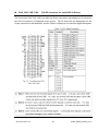
CON2 ~ CON5
(I/O connector for each AXIS)
The connectors CON2 ~ CON5 are 20-pin connectors that enable you to connect to the I/O
signals for general purpose motor drivers.
Fig. 2.2 shows the pin assignment for the 20-pin
connector on the DN-8468G, and the Table 2.3 shows its I/O connector signal description.
http:/www.icpdas.com
21
i8094_Getting_Started_V2.4
CON6
The connector CON6 is 16-pin connector that enables you to connect to the signals of your
motor drivers.
The FRnet connectors, FR-A and FR-B, can be used to serially connect a I/O
module of FRnet series, as FR-2053,FR-2057….
The more information, please refer to
web-site of ICPDAS :
http://www.icpdas.com/products/Remote_IO/frnet/frnet_introduction.htm
Fig.2.3 shows the pin assignment for the 16-pin connector on the DN-8468G, and the Table 2.4
shows its I/O connector signal description.
http:/www.icpdas.com
22
i8094_Getting_Started_V2.4
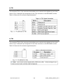
TB2
The connector TB2 is 5-pin connector that enables you to connect to the signals of your
motor drivers. Fig.2.4 shows the pin assignment for the 5-pin connector on the DN-8468G, and
the Table 2.5 shows its I/O connector signal description.
RJ1 (The I/O signals of the FRnet)
The connectors RJ1 is an 8-pin RJ45 connector that enable you to connect to the signals of
FRnet.
The FRnet connectors, FR-A and FR-B, can be used to serially connect a I/O module of
FRnet series, as FR-2053,FR-2057…. The more information, please refer to web-site of
ICPDAS:
http://www.icpdas.com/products/Remote_IO/frnet/frnet_introduction.htm
Fig.2.5shows the pin assignment for the 8-pin connector on the DN-8468G, and the Table 2.6
shows its I/O connector signal description.
http:/www.icpdas.com
23
i8094_Getting_Started_V2.4
2.2.3 Jumper and Switch Settings
JP7
Jumper 7 controls the EMG-A signal of the CON6 connector. The following diagram is shown the
selection condition of the jumper 7.
Fig. 2.6 Jumper 7 setting
JP8/9, JP10/11, JP12/13, JP14/15
The Jumper8~15 are used to set the signal type of the pulse output signals. The output signal
type could be differential line driver output or open collector output. The JP8 ~JP9 are set XPP、
XPM for X-axis(CON1), JP10 ~JP11 are for Y-axis, JP12 ~JP13 are for Z-axis and JP14 ~JP15
are for U-axis. The 2-3 Pin short is the differential line driver mode. The 1-2 Pin short is the Open
Collector mode, as below example
http:/www.icpdas.com
24
i8094_Getting_Started_V2.4
EMG SW
The emergency stop signal for each servo ampilfier can be selected from EMG SW.
number 1, 2 , 3, 4 on EMG SW are denoted as axis X, Y, Z, U, respectively.
default setting to connect the EMG singals to GND.
take effect.
The
Fig. 2.7 is the
The EMG signals from CN1 ~ CN4 will not
If the switch is disconnected as shown in Fig. 2.8, the emergency stop signals can
be controlled from EMG signals in CON6.
Fig. 2.7
EMG SW setting for normally GND
Fig. 2.8
http:/www.icpdas.com
(Default setting)
EMG SW setting for user controlled signals.
25
i8094_Getting_Started_V2.4
2.3 Input/Output Connections
The signal connections of all the I/O signals are described in this chapter. Please refer
the contents of this chapter befor wiring the cable between the i8094/i8094F and the
motor drivers.
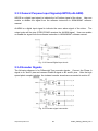
2.3.1 Pulse output signals
There are 4-axes pulse output signals on I8094/I8094F, For every axis, two pairs of CW
and CCW signals are used to send the pulse train. The CW and CCW signals can also
be programmed as PULSE and DIR signals pait. Two types of the pulse output signal,
Differential-Type and Open-Collector Type, can be selected from JP8/9, JP10/11, JP12/13, and
JP14/15 and are described in section 2.2.3. The following wiring diagram is for the CW and
CCW signals of the 4-axes.
Fig. 2.8 Differential-Type pulse output circuit
Fig. 2.9 The wiring is open collector output
Example: wiring of pulse signal
Two types of pulse output signal, Differential-Type and Open-Collector Type, can be
selected from JP8/9, JP10/11, JP12/13, and JP14/15 for each axis. The following wiring
diagram is an example to select pulse type of the output signal.
Fig. 2.10 Output pulse example
http:/www.icpdas.com
26
i8094_Getting_Started_V2.4
Pulse/Direction Pulse Output Mode:
In Pulse/Direction pulse output mode, the PULSE signal is output only at Pulse pins (P+,
P-). The driving direction is decided from the electric potential of Direction pins (N+, N-).
The following diagram is example signal of Pulse/Direction pulse output mode.
P±
N±
Positive Command
Negative Command
CW/CCW Pulse Output Mode:
In CW/CCW pulse output mode, the PULSE signal is output at both CW pins (P+, P-)
and CCW pins(N+, N-). At the same time, the driving direction is determined directly.
The following diagram is example signal of CW/CCW pulse output mode.
P±
N±
Positive Command
P±
N±
Negative Command
2.3.2 Connection for Limit switch Signal
Limit Switch Signal can prevent the over traveling appearance of the motion system.
User can set the hardware limit switch signal to be normal open or normal close by the
software instruction in I8094/I8094F software manual. The following figure indicates
that the photo couplers are used to keep out the sensor noise of the Limit Switch.
Fig. 2.11 Limit switch signal circuit
http:/www.icpdas.com
27
i8094_Getting_Started_V2.4
2.3.3 General Purpose Input Signals(nINPOS,nALARM)
INPOS is a digital input signal to indicate the In-Position signal of the driver. User can
enable or disable the signal from the software instruction in I8094/I8094F software
manual.
ALARM is a digital input signal to indicate the servo alarm signal of the driver. The
output pulse will be stop if PISO-PS400 receives the ALARM signal. User can enable
or disable the signal from the software instruction in I8094/I8094F software manual.
Fig. 2.12 General Digital Input circuit
2.3.4 Encoder Signals
The following diagram is for Differential-Type encoder signals. Connect the Phase A
signal to A+ and A- pins and connect Phase B signal to B+ and B- pins. After the high
speed photo coupler isolation, the isolated encoder signals are connected to motion IC.
Fig. 2.13 Encoder signal connection
http:/www.icpdas.com
28
i8094_Getting_Started_V2.4
2.3.5 Emergency Stop Signal
The following diagram is for Emergency STOP signal. If the emergency signal is
occurred, the output pulse for all axes will be STOP and the error flag will be set as 1.
After the photo coupler isolation, the isolated emergency signal is connected to motion
IC.
Fig. 2.14 Emergency Stop Signal connection
2.3.6 Manual Pulse Generator Input Signal (EXP+,EXP-)
The signals, EXP+ and EXP-, are used for manual pulsar signals. The following
diagram is an example connection for the external inputs. User can set the signals as
fixed pulse CW/CCW mode, continuous pulse CW/CCW mode, or A/B phase manual
pulsar mode by using the setting in section 3.5.
Fig. 2.15 EXP+/- connection diagram
http:/www.icpdas.com
29
i8094_Getting_Started_V2.4
2.3.7 General Purpose Output signals(Servo On/Off)
The following diagram is a digital output signal for driver Servo On/Off signal.
output signal enable or disable the driver.
The
Fig. 2.16 Servo On/Off signal connection diagram
http:/www.icpdas.com
30
i8094_Getting_Started_V2.4
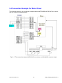
2.4 Connection Example for Motor Driver
The following diagram is the connection example between MITSUBISH MR-J2S AC servo driver
and the extension boardDN-8468G.
Fig. 2.17 The connection between MR-J2S AC servo driver and DN-8468G extension board.
http:/www.icpdas.com
31
i8094_Getting_Started_V2.4
3 Software Development Overview
3.1 Software development Overview
Please refer to the demo_start sample
http:/www.icpdas.com
32
i8094_Getting_Started_V2.4
3.1.1 Register Module
User must register for each I8094/I8094F module before sending command otherwise
user will get error. Please refer to i8094MF_REGISTRATION() function, the section 2.2
of I8094/I8094F user manual.
3.2 Safety IO Setting
There are many reasons to stop motion during driving.
this subsection.
Some reasons are described in
3.2.1 Emergency Stop Signal Input
The EMG-A input signal in CON6 is able to perform the emergency stop function
immediately for all of the 4 axes during driving. The emergency stop function can
prevent the critical damage occurrence from the critical accident. If user don’t use this
Emergency stop signal, please closing breaks between 2 and 3 of JP7 jumper.
Otherwise, please closing breaks between 1 and 2 of JP7 jumper and connecting the
EMG-A signal to CON6.
The EMG-X, EMG-Y, EMG-Z, and EMG-U input signals in CON6 are connected directly
to the driver for each axis. These signals are able to perform the emergency stop
function immediately for each driver during driving. User have to switch the EMG-SW
to normal ON and connect external signal source to enable these signals.
3.2.2 Configure the Servo ALARM Signals
When the ALARM signals are occurred from servomotor drivers, users can be notified by these
signals and determine what to do. The operating mode (Enable or Disable) and the proper trigger
level of these signals can be set by user. Please refer to i8094MF_SET_ALARM() function,
the section 2.13 of I8094/I8094F user manual.
http:/www.icpdas.com
33
i8094_Getting_Started_V2.4
3.2.3 Configure the Limit Switch Signals(±EL)
To insure the machine in safety, hardware limit switches are placed at the both ends of
machine traveling range.
If the machine touch the hardware limit switch sensors,
PISO-PS400 will stop immediately.
The operating mode (Enable or Disable) and the proper
trigger level of these signals can be set by user. Please refer to i8094MF_SET_HLMT ()
function, the section 2.6 of I8094/I8094F user manual.
3.2.4 Configure the Software Limite(±SEL)
To insure the machine in safety, hardware limit switches are placed at the both ends of
machine traveling range.
In addition, user can set the software limits to avoid the happening
of the over range before the hardware limit takes effect.
limits condition, PISO-PS400 will stop immediately.
If the machine reach the software
The operating mode (Enable or Disable)
and the proper trigger condition of these signals can be set by user. Please refer to
i8094MF_SET_SLMT () and i8094MF_CLEAR_SLMT() function, the section 2.10 of
I8094/I8094F user manual.
3.3 Error Checking
Check whether there is any error. If there are something wrongs, please use the
GET_ERROR_CODE() function to get the error-code, then check the reason and
remove it. Please refer to GET_ERROR_CODE() function, the section 3.6 of
I8094/I8094F manual.
User also can use i8094MF_GET_DI() function to check the all of DI status. Please refer
to i8094MF_GET_DI() function, the section 3.5 of I8094/I8094F user manual.
http:/www.icpdas.com
34
i8094_Getting_Started_V2.4
3.4 Basic Configuration of Motion
The basic Motion configuration is mainly aimed for general necsseary setting,
as below:
1 Pulse output mode setting: Pulse/Dir、CW/CCW…
i8094MF_SET_PULSE_MODE() (Please refer to the section 2.4 of I8094/I8094F
user manual )
2 Max. speed limitation setting for each axis
i8094MF_SET_MAX_V ()(Please refer to the section 2.5 of I8094/I8094F
user manual)
3 Encoder input setting
i8094MF_SET_ENCODER()(Please refer to the section 2.11 of I8094/I8094F
user manual)
4 DI noise filter setting( If necessary)
i8094MF_SET_FILTER()(Please refer to the section 2.15 of I8094/I8094F
user manual)
5 Circular motion declaration( Ring counter)( If necessary)
i8094MF_VRING_ENABLE()(Please refer to the section 2.16 of I8094/I8094F
user manual )
3.5 Manual Pulse Generator Testing
User can use the manual pulse generator function directly to drive motion forward or backward.
For further wiring and parameter tuning, user have to check the correction of the DI signals and
the moving direction.
The manual pulse generator can be achieved from three driving methods described
below:
1. A/B phase Manual Pulse Generator:
Use the A/B phase Manual Pulse Generator for forward/backward moving.
i8094MF_EXD_MP()( Please refer to the section 2.18.1 of I8094/I8094F user
manual)
http:/www.icpdas.com
35
i8094_Getting_Started_V2.4
2. Fixed-pulse driving Manual Pulse Generator:
User have to preset fixed driving pulses. After setting, user can push the forward
or backward button to drive fixed pulses for each direction.
i8094MF_EXD_FP()( Please refer to the section 2.18.2 of I8094/I8094F usere
manual)
3. Continuous- pulse driving Manual Pulse Generator:
User can preset output-pulse frequency.
After setting, user can push the forward or
backward button to drive fixed velocity for each direction. If user release the button, the
motion will be stop immediately.
i8094MF_EXD_CP ()( Please refer to section 2.18.3 of I8094/I8094F user
manual).
4 Disable external pulse input:
Disable external pulse input by this command after operating anyone of three
functions above.
i8094MF_EXD_DISABLE() ( Please refer to section 2.18.4 of I8094/I8094F user
manual)
http:/www.icpdas.com
36
i8094_Getting_Started_V2.4
3.6 Home Search
I8094 provides the home function of automatic search. Operate that automatically after
setting properly. The main steps is as bellow:
z Near-home sensor searching under high-speed motion.
z Home sensor searching under low-speed motion.
z Servomotor Z-phase searching under low-speed motion.
z Offset movement to the origin of the working area under high-speed motion.
User can select which steps are ignored when setting for the actual operation. It
performs automatically that economize the CPU resource and program code reducing.
Although there are four home search steps,but user can create more than 10 types of
different home search mode by vary with the software functions. It is attributed to the
configurable home search direction and perform it or not of each step.
3.6.1 Home Search Configuration
1. Logic level setting for Near home sensor and Home sensor ( If necessary)
i8094MF_SET_NHOME() ( Please refer to section 2.8 of I8094/I8094F user
manual)
2 Home sensor logic level setting
i8094MF_SET_HOME_EDGE() ( Please refer to section 2.9 of I8094/I8094F user
manual)
3 Home-speed setting
i8094MF_SET_HV() ( Please refer to section 5.1 of I8094/I8094F user manual)
i8094MF_SET_SV() ( Please refer to section 6.1.2 of I8094/I8094F user manual)
4 Home mode setting
i8094MF_SET_HOME_MODE()( Please refer to section 5.3 of I8094/I8094F user
manual)
http:/www.icpdas.com
37
i8094_Getting_Started_V2.4
3.6.2 Running the Home Search
1 Start homing
i8094MF_HOME _START()( Please refer to section 5.4 of I8094/I8094F user
manual)
2 Waiting for homing completion
i8094 _HOME_WAIT()( Please refer to section 5.5 of I8094/I8094F user manual)
http:/www.icpdas.com
38
i8094_Getting_Started_V2.4
3.7 Basic Motion
3.7.1 Speed Profie of the Motion Control
1 Symmetrical T-profile of motion volicety
(If SV is larger than V or equal to V, perform constant velocity driving)
2 Asymmetrical T-profile of motion velocity
3 Symmetrical S-curve of motion velocity
http:/www.icpdas.com
39
i8094_Getting_Started_V2.4
4 Asymmetrical S-curve of motion velocity
3.7.2 Basic Setting of Single Axis
1 Setting the mode of Acceleration/deceleration: There are four speed modes
0 Æ Symmetrical T-Profile (SV、V、A、AO)
1 Æ Symmetrical S-curve (SV、V、K、AO)
2 Æ Asymmetrical T-profile (SV、V、A、D、AO)
3 Æ Asymmetrical S-curve (SV、V、K、L、AO)
i8094MF_NORMAL_SPEED()( Please refer to section 6.1.1 of I8094/I8094F user
manual)
2 Setting the start velocity: Set lowest speed
i8094MF_SET_SV ()( Please refer to section 6.1.2 of I8094/I8094F user manual)
3 Setting the Velocity: Set the desired speed
i8094MF_SET_V ()( Please refer to section 6.1.3 of I8094/I8094F user manual)
4 Setting the Acceleration/Deceleration speed: Set the Acceleration/Deceleration speed.
i8094MF_ SET_A ()( Please refer to section 6.1.4 of I8094/I8094F user manual)
i8094MF_ SET_D ()( Please refer to section 6.1.5 of I8094/I8094F user manual)
http:/www.icpdas.com
40
i8094_Getting_Started_V2.4
3.7.3 Basic Motion of Single Axis
1 Fixed-pulse driving output: Perform fixed-quantity of single axis pulse output.
i8094MF_FIXED_MOVE()( Please refer to section 6.1.9 of I8094/I8094F user
manual)
2 Continuous-pulse driving output: Perform continuous pulse output of single axis.
i8094MF_CONTIUNE_MOVE ()( Please refer to section 6.1.10 of I8094/I8094F
user manual)
3 Waiting for motion done: Waiting for the axis driving accomplished.
i8094MF_STOP_WAIT()( Please refer to section 6.5.3 of I8094/I8094F user
manual)
3.7.4 Basic Setting of Muti-Axes Interpolation
1 Setting axes of interpolation: Select axes to do the interpolation.
i8094MF_AXIS_ASSIGN()( Please refer to section 6.2.1 of I8094/I8094F user
manual)
2 Setting the mode of Acceleration/Deceleration of vector: There are twelve mode as
below:
0 Æ 2-axes( Linear & ARC & Circular) Fixed-vector velocity (VV)
1 Æ 2-axes linear symmetrical T-profile (VSV、VV、VA、VAO)
2 Æ 2-axes linear symmetrical S-curve (VSV、VV、VK、VAO)
3 Æ 2-axes linear asymmetrical T-profile (VSV、VV、VA、VD、VAO)
4 Æ 2-axes linear asymmetrical S-curve (VSV、VV、VK、VL、VAO)
5 Æ 2-axes (ARC & Circular) symmetrical T-profile (VSV、VV、VA、VAO)
6 Æ 2-axes (ARC & Circular) asymmetrical T-profile (VSV、VV、VA、VD、VAO)
7 Æ 3-axesFixed-vector velocity (VV)
8 Æ 3-axes linear symmetrical T-profile (VSV、VV、VA、VAO)
9 Æ 3-axes linear symmetrical S-curve (VSV、VV、VK、VAO)
10 Æ 3-axes linear asymmetrical T-profile (VSV、VV、VA、VD、VAO)
11 Æ 3-axes linear asymmetrical S-curve (VSV、VV、VK、VL、VAO)
i8094MF_VECTOR_SPEED()( Please refer to section 6.2.2 of I8094/I8094F user
manaul)
2 Setting the start vector velocity: Set the lowest vector speed.
i8094MF_SET_VSV()( Please refer to section 6.2.3 of I8094/I8094F user
manual)
http:/www.icpdas.com
41
i8094_Getting_Started_V2.4
3 Setting the vector velocity: Set the desired vector speed
i8094MF_SET_VV()( Please refer to section 6.2.4 of I8094/I8094F user manual)
4 Setting the velocity of Acceleration/Deceleration of vector: Set the speed of
Acceleration/Deceleration of vector.
i8094MF_SET_VA()( Please refer to section 6.2.5 of I8094/I8094F user manual)
i8094MF_SET_VD()( Please refer to section 6.2.6 of I8094/I8094F user manual)
3.7.5 Basic Motion of Muti-Axes Interpolation
1 2-axes linear interpolation: Perform 2-axes linear interpolation.
i8094MF_LINE_2D()( Please refer to section 6.2.10 of I8094/I8094F user
manual)
2 3-axes linear interpolation: Perform 3-axes linear interpolation.
i8094MF_LINE_3D()( Please refer to section 6.2.11 of I8094/I8094F user
manual)
3 2-axes ARC interpolation: Perform 2-axes ARC interpolation.
i8094MF_ARC_CW ()( Please refer to section 6.2.12 of I8094/I8094F user
manual)
i8094MF_ARC_CCW ()( Please refer to section 6.2.12 of I8094/I8094F user
manual)
4 2-axesCircular interpolation: Perform 2-axes Circular interpolation.
i8094MF_ CIRCLE _CW ()( Please refer to section 6.2.13 of I8094/I8094F user
manual)
i8094MF_ CIRCLE _CCW ()( Please refer to section 6.2.13 of I8094/I8094F user
manual)
http:/www.icpdas.com
42
i8094_Getting_Started_V2.4
3.8 Advance Motion
1 2-axes continuous interpolation of rectangle: Perform2-axes continuous
interpolation of rectangle.
i8094MF_RECTANGLE()( Please refer to section 6.4.1 of I8094/I8094F user
manual)
2 2-axes continuous interpolation of line:
Initial setting continuous interpolation of 2-axes line( Symmetrical T-profile).
i8094MF_LINE_2D_INITIAL()( Please refer to section 6.4.2 of I8094/I8094F user
manual)
Perform 2-axes continuous interpolation of line.
i8094MF_LINE_2D_CONTINUE()( Please refer to section 6.4.2 of I8094/I8094F
user manual)
3 3-axes continuous interpolation of line:
Initial setting continuous interpolation of line( symmetrical T-profile).
i8094MF_LINE_3D_INITIAL()( Please refer to section 6.4.3 of I8094/I8094F user
manual)
Perform 3-axes continuous interpolation of line.
i8094MF_LINE_3D_CONTINUE() ( Please refer to section 6.4.3 of I8094/I8094F
user manual)
4 Others continuous interpolation: Muti-point continuous interpolation, 3-axes Helix
interpolation, 2-axes Ratio motion ( Please refer to section 6.4.4~6.4.7 of I8094/I8094F
user manual)
3.9 Synchronization Action
i8094 also offer many function of Synchronization Action, as compare EP, LATCH….and
so on( Please refer to section 6.3 of I8094/I8094F user manaul)
http:/www.icpdas.com
43
i8094_Getting_Started_V2.4
4 GETTING STARTED OF SOFTWARE
4.1 WinCon eVC++ Guideline
4.1.1 Confirm the Relative Files
Please confirm you have the following relevance files:
1. I8094.lib
2. I8094.dll
3. I8094.h
If you don’t have, please look for CD or download the latest edition from
ICPDAS’s website http://www.icpdas.com/download/download-list.htm .
4.1.2 Create a new eVC++ Application Project
Please execute the Microsoft eVC++ 4.0. Then click“File” -> “New” to create a new
application project. In the “Projects“ property page, choose“WCE MFC AppWizard
(exe)"option and specifythe project name ”Demo_First”, then key in the disk path in
the “Location” field, then select the“Win 32[WCE ARMV4]“ in CPU list. If necessary,
please also select others options together. And then click "OK".
Choose “ Dialog based “ and click “NEXT”
http:/www.icpdas.com
44
i8094_Getting_Started_V2.4
Click “Finish” and finish the new project establishment.
http:/www.icpdas.com
45
i8094_Getting_Started_V2.4
4.1.3 Add the I8094.h into eVC++ Application Project
Add the i8094h into the WorkSpace of application project, as below:
Click the right key of mouse on Header Files, then choose “Add Files to Folder….”
It will appear on a dialog of selecting file, find out the I8094.h and click OK.
http:/www.icpdas.com
46
i8094_Getting_Started_V2.4
4.1.4 Add the Reference Path into eVC++ Application Project
A.
Open the “Options” dialog in “Tools” menu.
B. Select “Directories“ , then select the “SA_IA” in “Platform” item. Then select the
“Win32 [WCE ARMV4]” in “CPUS” item and select the “include files” in “Show
directories“ item.
C. Add in the path of including files. Double-click the rectangle in the buttom of
Directories"List-Box. Please key in the specific path that your header files
located. For instance, C:\DAQPRO\Wincon\inc, as below snapshot.
D. Then select the “Library files” in “Show directories” item.
E. Add in the path of library files. Double-click the rectangle in the buttom of
Directories"List-Box. Please key in the specific path that your header files
located. For instance, C:\DAQPRO\Wincon\lib, as below snapshot.
http:/www.icpdas.com
47
i8094_Getting_Started_V2.4
4.1.5 Start the eVC++ Sample
Add a BUTTON on Dialog, as below snapshot:
Double-click on BUTTON and generate subprogram, then add ”#include “i8094.h”,
“WinConSDK.h”, and declare CI8094MF I8094MF & bool Driver_Open & BYTE
cardNo=0 in start point, as below snapshot:
Because we have built a class “CI8094MF(For Macro function)”, it is convenient to guide
in designing program. User also can use the function of manual directly. Double-click on
http:/www.icpdas.com
48
i8094_Getting_Started_V2.4
BUTTON that will generate a subprogram, then key in “I8094MF”, then it will appear a
windows guide to help user to select a relevance function.
Select “i8094MF.REGISTRATION” and key in (cardNo,3), that indicate the i8094( or
i8094F) on third slot is registered to 0th module. The detailed procedure is as below:
//====='Step 1 Driver init
if
(!Driver_Open)
{
I8094MF.REGISTRATION(cardNo,3);
Driver_Open = true;
}
//====='Step 2 CONFIG IO
I8094MF.RESET_CARD (cardNo);
I8094MF.SET_PULSE_MODE (cardNo, AXIS_XYZU, 2);
//set the pulse output mode
I8094MF.SET_ALARM (cardNo, AXIS_XYZU, 0, 0);
//disable the SERVO ALARM Input
I8094MF.SET_ENCODER (cardNo, AXIS_XYZU, 0, 0, 0);
//set the encoder input type
I8094MF.SET_MAX_V (cardNo, AXIS_XYZU, 16000);
//set the max speed for XYZU
I8094MF.EXD_DISABLE (cardNo, AXIS_XYZU);
//set the external input Off
I8094MF.SET_LP (cardNo, AXIS_XYZU, 0);
//set the Logic position =0
I8094MF.SET_EP (cardNo, AXIS_XYZU, 0);
//set the Encoger position =0
I8094MF.SET_A (cardNo, AXIS_XYZU, 1000);
//set the Acc =1000
I8094MF.SERVO_ON (cardNo, AXIS_XYZU);
//set the Servo_ON to servo motors
//======'Step 3 Check ERROR
http:/www.icpdas.com
49
i8094_Getting_Started_V2.4
WORD KK=0;
KK= I8094MF.GET_ERROR(cardNo);
CString MSGG;
if (KK != YES)
{
//No ERROR: Step 4 Move X axis
BYTE axis=AXIS_X;
//for AXIS_X it can be to AXIS_XYZU
I8094MF.SET_MAX_V(cardNo, axis, 20000);
I8094MF.NORMAL_SPEED(cardNo, axis, 0);
//set axis as Symmetrical T curve mode
I8094MF.SET_V(cardNo, axis, 20000);
//set v=10000 PPS
I8094MF.SET_A(cardNo, axis, 100000);
//set acc=100000 PPS/S
I8094MF.SET_SV(cardNo, axis, 10);
//set start speed=1000 PPS
I8094MF.SET_AO(cardNo, axis, 0);
//set offset pulse (at SV speed)= 0 PS
I8094MF.FIXED_MOVE(cardNo, axis, 10000);
//run the fixed 10000 Pulse move.
while (I8094MF.STOP_WAIT(cardNo, axis) == NO)
{
DoEvents();
Sleep(1);
//wait for axis to stop
}
long AA= I8094MF.GET_LP(cardNo,axis);
//Get X Now position
}
else
{
//Please check the ERROR CODE
//Get X ERROR CODE
KK= I8094MF.GET_ERROR_CODE(cardNo, AXIS_X);
//Get Y ERROR CODE
KK= I8094MF.GET_ERROR_CODE(cardNo, AXIS_Y);
//Get Z ERROR CODE
KK= I8094MF.GET_ERROR_CODE(cardNo, AXIS_Z);
//Get U ERROR CODE
KK= I8094MF.GET_ERROR_CODE(cardNo, AXIS_U);
//====================================
}
Please refer to the example “demo_First”
After you finished that, please choose the “Project”->”Setting” menu will appear the a
http:/www.icpdas.com
50
i8094_Getting_Started_V2.4
dialgo as below, then select the “Link” item and key in “WinConSDK.lib i8094.lib”(as
below snapshot) into the Object/library modules box and the click OK.
4.1.6 Build the Project
Please select the “Build” -> ”Build All” in the menu, then you will be finished this example
program if there isn’t any wrong.
http:/www.icpdas.com
51
i8094_Getting_Started_V2.4
4.1.7 Download and Run
Please copy the ”i8094Demo.exe” and “I8094.dll” into the same floder of WinCon ( User
can use the eVC++ Online Download/FTP/USB disk to do), then execute it.
http:/www.icpdas.com
52
i8094_Getting_Started_V2.4
4.2 Microsoft Visual Studio .NET 2003(VB.NET,C#) Guideline
Because the Microsoft Visual Studio .NET 2003 has similar environment, therefore we
make an example with VB.NET.
4.2.1 Confirm the Relative Files
Please confirm you have the following relevance files:
i8094.dll
i8094_NET.dll
If you don’t have, please look for CD or download the latest edition from
ICPDAS’s website http://www.icpdas.com/download/download-list.htm
4.2.2 Create a new VB.NET/C# Application Project
Please execute the Microsoft Visual Studio .NET 2003. Then create a new application
project of VB and select “ Smart Device Application”, as below snapshot:
Click “OK” after finishing all of the selecting, then go to next step.
http:/www.icpdas.com
53
i8094_Getting_Started_V2.4
Select the “WinDows CE” and “Windows Application”, then click “OK”.
http:/www.icpdas.com
54
i8094_Getting_Started_V2.4
4.2.3 Add the DLL into Application Project
Click the right key of mouse on”Solution Explorer” =>add Reference
=>Select “Browse” button.
http:/www.icpdas.com
55
i8094_Getting_Started_V2.4
Select the i8904 _NET.DLL
Select the “Open” button, as above snapshot:
http:/www.icpdas.com
56
i8094_Getting_Started_V2.4
4.2.4 Start the VB.NET/C# Sample
Add a “BUTTON” on the Form1, then double-click the BUTTON, then it will appear a
code of Form1.vb, then add the “imports i8094MF_NET” in top, as below snapshot:
Add the “i8094MF” into the Button1_Click, then it will appear a windows guide to help
user to select a relevance function.
http:/www.icpdas.com
57
i8094_Getting_Started_V2.4
Detailed code as below:
'====='Step 1 Driver init
If Not Driver_Open Then
i8094MF.i8094MF_REGISTRATION(cardNo, 1)
Driver_Open = True
End If
'====='Step 2 CONFIG IO
i8094MF.i8094MF_RESET_CARD(cardNo)
i8094MF.i8094MF_SET_PULSE_MODE(cardNo, AXIS_XYZU, 2)
i8094MF.i8094MF_SET_ALARM(cardNo, AXIS_XYZU, 0, 0)
'set the pulse output mode
'disable the SERVO ALARM Input
i8094MF.i8094MF_SET_ENCODER(cardNo, AXIS_XYZU, 0, 0, 0) 'set the encoder input type
i8094MF.i8094MF_SET_MAX_V(cardNo, AXIS_XYZU, Convert.ToUInt32(16000))
i8094MF.i8094MF_EXD_DISABLE(cardNo, AXIS_XYZU)
'set the max speed for XYZU
'set the external input Off
i8094MF.i8094MF_SET_LP(cardNo, AXIS_XYZU, 0)
'set the Logic position =0
i8094MF.i8094MF_SET_EP(cardNo, AXIS_XYZU, 0)
'set the Encoger position =0
i8094MF.i8094MF_SET_A(cardNo, AXIS_XYZU, Convert.ToUInt32(1000))
i8094MF.i8094MF_SERVO_ON(cardNo, AXIS_XYZU)
'set the Acc =1000
'set the Servo_ON to servo motors
'======'Step 3 Check ERROR
Dim KK As Long = 0
KK = i8094MF.i8094MF_GET_ERROR(cardNo)
Dim MSGG As String
If (KK <> YES) Then
'No ERROR: Step 4 Move X axis
Dim axis As UInt16 = AXIS_X 'for AXIS_X it can be to AXIS_XYZU
i8094MF.i8094MF_SET_MAX_V(cardNo, axis, Convert.ToUInt32(20000))
i8094MF.i8094MF_NORMAL_SPEED(cardNo, axis, Convert.ToUInt16(0))
'set axis as Symmetrical T curve
mode
i8094MF.i8094MF_SET_V(cardNo, axis, Convert.ToUInt32(20000))
'set v=10000 PPS
i8094MF.i8094MF_SET_A(cardNo, axis, Convert.ToUInt32(100000))
i8094MF.i8094MF_SET_SV(cardNo, axis, Convert.ToUInt32(10))
i8094MF.i8094MF_SET_AO(cardNo, axis, 0)
'set acc=100000 PPS/S
'set start speed=1000 PPS
'set offset pulse (at SV speed)= 0 PS
i8094MF.i8094MF_FIXED_MOVE(cardNo, axis, 10000) 'run the fixed 10000 Pulse move.
Do While (i8094MF.i8094MF_STOP_WAIT(cardNo, axis) = NO)
i8094MF.system.DoEvents()
System.Threading.Thread.Sleep(1)
'wait for axis to stop
Loop
Dim AA As Long = i8094MF.i8094MF_GET_LP(cardNo, axis)
'Get X Now position
Else
http:/www.icpdas.com
58
i8094_Getting_Started_V2.4
'Please check the ERROR CODE
'Get X ERROR CODE
KK = Convert.ToInt32(i8094MF.i8094MF_GET_ERROR_CODE(cardNo, AXIS_X))
'Get Y ERROR CODE
KK = Convert.ToInt32(i8094MF.i8094MF_GET_ERROR_CODE(cardNo, AXIS_Y))
'Get Z ERROR CODE
KK = Convert.ToInt32(i8094MF.i8094MF_GET_ERROR_CODE(cardNo, AXIS_Z))
'Get U ERROR CODE
KK = Convert.ToInt32(i8094MF.i8094MF_GET_ERROR_CODE(cardNo, AXIS_U))
'====================================
End If
Please refer to a example “ demo_First”
4.2.5 Build the Project
Please select the “Build” -> ”Build Solution” in pull-down menu, then you will be finished
this example program if there isn’t any wrong.
4.2.6 Download and Run
Please copy the ”Demo_First.exe”, “I8094.dll” and “I8094_NET.dll” into the same floder
of WinCon ( User can use the VS.NET Online Download/FTP/USB disk to do), then
execute it.
http:/www.icpdas.com
59
i8094_Getting_Started_V2.4
4.3 I-8000 Turbo C Guideine
4.3.1 Confirm the Relative Files
Please confirm you have the following relevance files:
I8094.lib
I8094.h
I8000.lib
I8000.h
If you don’t have, please look for CD or download the latest edition from
ICPDAS’s website http://www.icpdas.com/download/download-list.htm
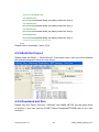
4.3.2 Create a new TC ++ Application Project
1. Execute the TC.EXE in the demo100 folder, then create a new
Project( demo100.prj).
2. Add the contents of project:demo100.cpp and ..\lib\8000l.lib,I8094.lib
3. Setting the relevance option
http:/www.icpdas.com
60
i8094_Getting_Started_V2.4
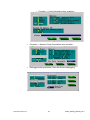
Compiler -> Code Generation item as below:
http:/www.icpdas.com
Compiler -> Advance Code Generation item as below:
Debugger setting as below, close the Source debugging.
61
i8094_Getting_Started_V2.4
4.3.3 Start the TC Sample
1. Add the declared contents into the demo100.cpp:
#include <dos.h>
#include <math.h>
#include "8000.h"
#include "I8094.h"
BYTE cardNo;
long x_value, y_value, z_value, u_value;
2. Add the relevance code into the main program( Please refer to demo100.cpp):
void main ()
{
//=================== I-8000 ===================
//Set (slot0~slot7) = cardNO (1~8)。
BYTE slot;
int Found = 0;
for (slot = 0; slot < 8; slot++)
{
cardNo = slot + 1;
if (i8094MF_REGISTRATION(cardNo, slot) == YES)
{
//Found Axis Card。
i8094MF_RESET_CARD(cardNo);
Found++;
}
}
if (Found == 0)
{
//Not Found。
Print("I-8094 card not found ! \r\n");
return;
}
cardNo = 1;
i8094MF_INIT_CARD(cardNo);
i8094MF_SET_PULSE_MODE(cardNo, AXIS_XYZU, 2);
i8094_IN3_LEVEL(cardNo,AXIS_XYZU, 1);
http:/www.icpdas.com
62
i8094_Getting_Started_V2.4
i8094MF_SET_ALARM(cardNo, AXIS_XYZU, 1, 1);
i8094MF_SET_ENCODER(cardNo, AXIS_XYZU, 0, 0, 0);
i8094MF_SET_MAX_V(cardNo, AXIS_XYZU, 16000);
//==========================================================================
BYTE ret1 = 0;
BYTE chkey;
DWORD sv;
//PPS
DWORD v;
//PPS
DWORD a;
//PPS/s
i8094MF_SERVO_ON(cardNo, AXIS_XYZU);
do
{
Print(" (0:Exit, 1:HELIX_3D_1, 2:HELIX_3D_2, 3:RATIO, 4:FRnet output, 5:FRnet input)
\r\n");
Print(" (6:Reset Encoder, 7:Stop, 8:Clear Error) \r\n");
Print(" (X:Jog X, Y:Jog Y, Z:Jog Z, U:Jog U, S:Stop Jog) \r\n");
Print("\n");
Print("----------------------LOGIC AND REAL POSITION COUNTER----------------------\n");
x_value = i8094MF_GET_LP(cardNo, AXIS_X);
y_value = i8094MF_GET_LP(cardNo, AXIS_Y);
z_value = i8094MF_GET_LP(cardNo, AXIS_Z);
u_value = i8094MF_GET_LP(cardNo, AXIS_U);
Print("LOGIC POSITION: x=%10ld,
y= %10ld, z= %10ld, u=%10ld \r\n", x_value, y_value,
z_value, u_value);
x_value = i8094MF_GET_EP(cardNo, AXIS_X);
y_value = i8094MF_GET_EP(cardNo, AXIS_Y);
z_value = i8094MF_GET_EP(cardNo, AXIS_Z);
u_value = i8094MF_GET_EP(cardNo, AXIS_U);
Print("REAL POSITION: x=%10ld,
y= %10ld, z= %10ld, u=%10ld \r\n", x_value, y_value,
z_value, u_value);
while (!Kbhit());
chkey=Getch();
Print("%s\r\n",&chkey);
switch (chkey)
{
case '0':
i8094MF_RESET_CARD(cardNo);
Print("EXIT! \r\n");
http:/www.icpdas.com
63
i8094_Getting_Started_V2.4
return;
//--------------------------------------------------------------case '1':
v=50000;//PPS。
i8094MF_SET_MAX_V(cardNo, AXIS_XYZU,160000L);
ret1=i8094MF_HELIX_3D(cardNo, AXIS_Y, AXIS_Z, AXIS_X, 1, v, 0,
1000, 5, -2000);
Delay(1000);
Print("HELIX_3D_1 ! \r\n");
Print("ret1= %d \r\n",ret1);
break;
//--------------------------------------------------------------case '2':
v=100000;//PPS。
i8094MF_SET_MAX_V(cardNo, AXIS_XYZU,1600000L);
ret1=i8094MF_HELIX_3D(cardNo, AXIS_Y, AXIS_Z, AXIS_U, 1, v, 0,
25000, 10, 3600);
Delay(2000);
Print("HELIX_3D_2 ! \r\n");
Print("ret1= %d \r\n",ret1);
break;
//--------------------------------------------------------------case '3':
sv=300;//PPS。
v=30000;//PPS。
a=500000;//PPS/s。
int loop1;
int loop2;
float ratio;
i8094MF_SET_MAX_V(cardNo, AXIS_XYZU,160000L);
Print("RATIO_2D ratio ? \r\n");
Scanf("%f", &ratio);
Print("ratio= %f \r\n",ratio);
i8094MF_RATIO_INITIAL(cardNo,AXIS_U, AXIS_X, sv, v, a, ratio);
for (loop2 = 0; loop2 < 5; loop2++)
{
for (loop1 = 0; loop1 < 5; loop1++)
{
http:/www.icpdas.com
64
i8094_Getting_Started_V2.4
i8094MF_RATIO_2D(cardNo, 0, 3600, 0);
i8094MF_RATIO_2D(cardNo, 0, 3600, 1);
}
i8094MF_RATIO_2D(cardNo, 0, 7200, 0);
i8094MF_RATIO_2D(cardNo, 0, 3600, 1);
}
i8094MF_RATIO_2D(cardNo, 1, 7200, 1);
Delay(3000);
Print("RATIO_2D OK ! \r\n");
break;
//--------------------------------------------------------------case '4':
WORD wSA;
WORD data;
Print("FRnet wSA ? \r\n");
Scanf("%d", &wSA);
Print("FRnet 16 bits data ? \r\n");
Scanf("%d", &data);
i8094MF_FRNET_SA(cardNo, wSA, data);
break;
//--------------------------------------------------------------case '5':
WORD wRA;
Print("FRnet wRA ? \r\n");
Scanf("%d", &wRA);
long data1 = i8094MF_FRNET_RA(cardNo, wRA);
Print("FRnet 16 bits data = %10ld \r\n", data1);
break;
//--------------------------------------------------------------case '6':
i8094MF_SET_LP(cardNo, AXIS_XYZU, 0);
i8094MF_SET_EP(cardNo, AXIS_XYZU, 0);
Print("RESET Encoder ! \r\n");
break;
//--------------------------------------------------------------case '7':
i8094MF_STOP_SLOWLY(cardNo, AXIS_XYZU);
Print("STOP! \r\n");
http:/www.icpdas.com
65
i8094_Getting_Started_V2.4
break;
//--------------------------------------------------------------case '8':
i8094MF_CLEAR_ERROR(cardNo);
Print("CLEAR ERROR ! \r\n");
break;
//--------------------------------------------------------------case 88:
case 120:
BYTE m_Axis=AXIS_X;
i8094MF_SET_MAX_V(cardNo, m_Axis, 32000);
i8094MF_NORMAL_SPEED(cardNo, m_Axis, 0);//set axis as
Symmetrical T curve mode
i8094MF_SET_A(cardNo, m_Axis, 50000);//set Acc =50000 PPS/S
i8094MF_SET_V(cardNo, m_Axis, 50000);
i8094MF_EXD_MP(cardNo, AXIS_X, 100);
i8094MF_EXD_DISABLE(cardNo, AXIS_Y);
i8094MF_EXD_DISABLE(cardNo, AXIS_Z);
i8094MF_EXD_DISABLE(cardNo, AXIS_U);
break;
//--------------------------------------------------------------case 89:
case 121:
m_Axis=AXIS_Y;
i8094MF_SET_MAX_V(cardNo, m_Axis, 32000);
i8094MF_NORMAL_SPEED(cardNo, m_Axis, 0);
//set axis as
Symmetrical T curve mode
i8094MF_SET_A(cardNo, m_Axis, 50000);//set Acc =50000 PPS/S
i8094MF_SET_V(cardNo, m_Axis, 100000);
i8094MF_EXD_MP(cardNo, AXIS_Y, 100);
i8094MF_EXD_DISABLE(cardNo, AXIS_X);
i8094MF_EXD_DISABLE(cardNo, AXIS_Z);
i8094MF_EXD_DISABLE(cardNo, AXIS_U);
break;
//--------------------------------------------------------------case 90:
case 122:
m_Axis=AXIS_Z;
http:/www.icpdas.com
66
i8094_Getting_Started_V2.4
i8094MF_SET_MAX_V(cardNo, m_Axis, 32000);
i8094MF_NORMAL_SPEED(cardNo, m_Axis, 0);
//set axis as
Symmetrical T curve mode
i8094MF_SET_A(cardNo, m_Axis, 50000);//set Acc =50000 PPS/S
i8094MF_SET_V(cardNo, m_Axis, 10000);
i8094MF_EXD_MP(cardNo, AXIS_Z, 100);
i8094MF_EXD_DISABLE(cardNo, AXIS_X);
i8094MF_EXD_DISABLE(cardNo, AXIS_Y);
i8094MF_EXD_DISABLE(cardNo, AXIS_U);
break;
//--------------------------------------------------------------case 85:
case 117:
m_Axis=AXIS_U;
i8094MF_SET_MAX_V(cardNo, m_Axis, 32000);
i8094MF_NORMAL_SPEED(cardNo, m_Axis, 0);
//set axis as
Symmetrical T curve mode
i8094MF_SET_A(cardNo, m_Axis, 50000);//set Acc =50000 PPS/S
i8094MF_SET_V(cardNo, m_Axis, 10000);
i8094MF_EXD_MP(cardNo, AXIS_U, 5);
i8094MF_EXD_DISABLE(cardNo, AXIS_X);
i8094MF_EXD_DISABLE(cardNo, AXIS_Y);
i8094MF_EXD_DISABLE(cardNo, AXIS_Z);
break;
//--------------------------------------------------------------case 83:
case 115:
i8094MF_EXD_DISABLE(cardNo, AXIS_X);
i8094MF_EXD_DISABLE(cardNo, AXIS_Y);
i8094MF_EXD_DISABLE(cardNo, AXIS_Z);
i8094MF_EXD_DISABLE(cardNo, AXIS_U);
break;
//--------------------------------------------------------------default:
break;
}
} while (1);
}
http:/www.icpdas.com
67
i8094_Getting_Started_V2.4
4.3.4 Build the Project
Click F9 to compile program, LINK or demo100.EXE。
4.3.6 Download and Run
1. Please execute the “7188.EXE” on computer (The “7188.EXE” is a executed
file of DOS, it can be used in DOS or DOS BOX of Win9X/WINNT/WIN2K).
2. Please depend on actual wiring "COM PORT" that assign to "COM1(ALT_1)" or
"COM2(ALT_2)" and set the transmission speed to “115200,N,8,1”.
3. Turn on the power of I-8000. It will have two situation:
o
It will appear a version of MiniOs7 message if the ” INIT*” connected to
“ INIT*COM”, then appear I-8000>。
o
The I-8000 will run the “AUTOEXEC.BAT” if the “INIT*“ unconnected, then
appear I-8000>。
4. User can start to make a command of I-8000 after appearing the “I-8000>”, as
below drawing:
http:/www.icpdas.com
68
i8094_Getting_Started_V2.4
5. Press the F2 button on the keyboard, then key in “demo100.exe”, then press the
F10 button to download and execute demo100.exe, as following drawing:
Please refer to the 7188 getting started manual.
http:/www.icpdas.com
69
i8094_Getting_Started_V2.4
APPENDIX-A Setup Tools & Others
A.1 Setup the Development Environment of I8094
A.1.1 eVC ++ 4.0
1. Microsoft eVC++ 4.0: at least ServicPack2 (Have already got at present
ServicPack4)
2. WinCon8000_EVC4_SP1: WinCon in eVC++ Development Environment
(SA_IA)
3. WinConSDK:WinCon Software Tool(inc,lib,dll,demo…)
A.1.2 Visual Studio .NET 2003(VB.NET,C#)
1. Above Microsoft Visual Studio.NET 2003 professional, including a
SmartDeviceApplication item
2. Debug Tool: Windows CE .NET Utilities v1.1 for Visual Studio .NET 2003
3. WinConSDK:WinCon software Tool(inc,lib,dll,demo…)
A.1.3 Turbo C
1. Above boland Turbo C 2.0
http:/www.icpdas.com
70
i8094_Getting_Started_V2.4
A.2 I8094 Surface
http:/www.icpdas.com
71
i8094_Getting_Started_V2.4
A.3 Dimensions
http:/www.icpdas.com
72
i8094_Getting_Started_V2.4
A.4 The Version Upgrades Note
//========= V 1.5.1.1 ==================
Changed the FUNCTION section
Add section 3.9 Synchronization Motion
//========= V 1.4.0.1 ==================
i8094_* ==>i8094MF_* (All Macro Function)
i8094_MF.DLL ==>i8094.DLL
i8094_MF.h ==>i8094.h
i8094_MF_NET.DLL ==>i8094_NET.DLL
i8094 Macro Function Manual ==> Getting Start manual of i8094 motion
controlmodule
Demo_First Changed(eVC++ and VB.NET)
Add section 5.1 Setup the Development Environment of I8094
http:/www.icpdas.com
73
i8094_Getting_Started_V2.4
APPENDIX-B Others Terminal Boards
B.1 DN-8468M Daughter Board
The DN-8468M is the daughter board for Mitsubitch J2 Series Amplifier.
It has 4-axis I/O
signals.
B.1.1 Board Layout for DN-8468M
107mm
JP4 JP3
JP5
Fig. 1-1
http:/www.icpdas.com
CN-YB
CN2
CN4
U
EMG
SW
TB2
CN8
CN-ZA
CN7
DN-8468M
Y
CN-UB
Z
JP2
CON1
68 PIN SCSI
CN-XB
CN-ZB
CN3
162mm
CN1
JP1
X
CN6
CN-YA
RJ1
CN-UA
CN-XA
CN5
TB1
Board layout for the DN-8468M
74
i8094_Getting_Started_V2.4
B.1.2 Signal Connections for DN-8468M
Maintaining signal connections is one of the most important factors in ensuring that your
application system is sending and receiving data correctly.
Pin Assignment for CON1
The I/O connector on the DN-8468M is a 68-pin SCSI II connector that enables you to connect to
the PISO-PS400 motion card. Please refer to the section 2.2.1( page 15).
TB1
The connector TB1 is 7-pin connector that enables you to connect to the signals of your motor
drivers. Fig.1-3 shows the pin assignment for the 7-pin connector on the DN-8468M, and the
Table 1-4 shows its I/O connector signal description.
TB2
The connector TB2 is 5-pin connector that enables you to connect to the signals of your motor
drivers. Fig.1-4 shows the pin assignment for the 5-pin connector on the DN-8468M, and the
Table 1-5 shows its I/O connector signal description.
http:/www.icpdas.com
75
i8094_Getting_Started_V2.4
CN-XA, CN-YA, CN-ZA, CN-UA
(CNA connector for each AXIS )
The connectors CN-XA, CN-YA, CN-ZA, and CN-UA are 20-pin connectors that enable you to
connect to the CNA connector of Mitsubishi motor drivers.
Fig.1-5 shows the pin assignment for
the 20-pin connector on the DN-8468M, and the Table 1-6 shows its I/O connector signal
description.
Table
1-6 CNA Signal Connection
Fig. 1-5 Pin definition for CN-XA,
CN-YA, CN-ZA, CN-UA
http:/www.icpdas.com
76
i8094_Getting_Started_V2.4
CN-XB, CN-YB, CN-ZB, CN-UB
(CNB connector for each AXIS )
The connectors CN-XB, CN-YB, CN-ZB, and CN-UB are 20-pin connectors that enable you to
connect to the CNB connector of your motor drivers.
Fig.1-6 shows the pin assignment for the
20-pin connector on the DN-8468M, and the Table 1-7 shows its I/O connector signal description.
Table 1-7 CNB Signal Connection
Fig. 1-6
Pin definition for CN-XB, CN-YB
CN-ZB, CN-UB
http:/www.icpdas.com
77
i8094_Getting_Started_V2.4
CN1~CN4 (The I/O signals of the X, Y, Z, U AXIS )
The connectors CN1~CN4 are 11-pin connectors that enable you to connect to the signals of
your motor drivers. Fig.1-7 shows the pin assignment for the 20-pin connector on the DN-8468M,
and the Table 1-8 shows its I/O connector signal description.
Table 1-8 CN1~4 Signal Connection
Name
Number Description
ERC
12
Error Count Clear
EXT_PWR
11
EXT POWER 24V
EMG
10
Emergent Stop
LMT+
9
Limit switch Input
Signal(+)
LMT-
8
Limit switch Input Signal(-)
INPUT3
7
Input Signal (IN3)
NRHOME
6
Near HOME Sensor Input
Signal
HOME
5
HOME Sensor Input
Signal
RESET
4
RESET Input Signal
EXP+
3
EXT Positive Direction
Pulse(+)
EXP-
2
Fig 1-7 Pin definition for CN1~ CN4
Pulse(-)
EXT_GND
http:/www.icpdas.com
EXT Positive Direction
78
1
EXT POWER Ground
i8094_Getting_Started_V2.4
CN5~CN8 (The I/O signals of the X, Y, Z, U AXIS )
The connectors CN5~CN8 are 15-pin connectors that enable users to connect the signals to
external motor drivers.
Fig.1-8 shows the pin assignment for the 15-pin connector on the
DN-8468M, and the Table 1-9 shows its I/O connector signal description.
Table 1-9 CN5~8
Fig. 1-8 Pin definition for CN5~CN8
http:/www.icpdas.com
79
i8094_Getting_Started_V2.4
RJ1 (The I/O signals of the FRnet)
The connectors RJ1 is an 8-pin RJ45 connector that enable you to connect to the signals of
FRnet.
Fig.1-9 shows the pin assignment for the 8-pin connector on the DN-8468M, and the
Table 1-10 shows its I/O connector signal description.
Fig. 1-9 Pin definition for RJ1
http:/www.icpdas.com
80
i8094_Getting_Started_V2.4
B.1.3 Jumper and Switch Settings
JP5
Jumper 5 controls the EMG-A signal of the TB1 connector. The following diagram is shown the
selection condition of the jumper 5.
Fig. 1-10 Jumper 5 setting
JP1, JP2
The encoder signals of axis X and axis Y can be chosen from servo driver encoder or external
encoder.
Fig. 1-11 shows that the encoder signals are selected from servo driver encoder.
In
meantime, Fig. 1-12 shows that the encoder signals are selected from external encoder.
Fig. 1-11 Primary encoder signals setting
Fig. 1-12 External encoder signals setting
http:/www.icpdas.com
81
i8094_Getting_Started_V2.4
EMG SW
The emergency stop signal for each servo ampilfier can be selected from EMG SW. The
number 1, 2 , 3, 4 on EMG SW are denoted as axis X, Y, Z, U, respectively. Fig. 1-13 is the
default setting to connect the EMG singals to GND. The EMG signals from CN1 ~ CN4 will not
take effect. If the switch is disconnected as shown in Fig. 1-14, the emergency stop signals can
be controlled from EMG signals in CN1 ~ CN4.
Fig. 1-13
EMG SW setting for normally GND
Fig. 1-14
http:/www.icpdas.com
(Default setting)
EMG SW setting for user controlled signals.
82
i8094_Getting_Started_V2.4
B.2 DN-8468P Daughter Board
The DN-8468P is the daughter board for Panasonic A4 Series Ampilifier.
It has 4-axis I/O
signals.
B.2.1 Board Layout for DN-8468P
107mm
CN6
CN5
TB1
RJ1
JP2
162mm
X
Y
CN7
DN-8468P
Fig. B2-1
http:/www.icpdas.com
TB2
CN8
EMG
SW
CNU
CNZ
CN4
U
CN3
Z
CON1
68 PIN SCSI
CN2
JP1
CNY
JP5
CN1
CNX
JP4 JP3
Board layout for the DN-8468P
83
i8094_Getting_Started_V2.4
B.2.2 Signal Connections for DN-8468P
Maintaining signal connections is one of the most important factors in ensuring that your
application system is sending and receiving data correctly.
Pin Assignment for CON1
The I/O connector on the DN-8468P is a 68-pin SCSI II connector that enables you to connect to
the PISO-PS400 motion card. Please refer to the section 2.2.1( page 15).
TB1
The connector TB1 is 7-pin connector that enables you to connect to the signals of your motor
drivers. Fig.1-3 shows the pin assignment for the 7-pin connector on the DN-8468P, and the
Table 1-4 shows its I/O connector signal description.
TB2
The connector TB2 is 5-pin connector that enables you to connect to the signals of your motor
drivers. Fig.1-4 shows the pin assignment for the 5-pin connector on the DN-8468P, and the
Table 1-5 shows its I/O connector signal description.
http:/www.icpdas.com
84
i8094_Getting_Started_V2.4
CNX, CNY, CNZ, CNU
(CN X5 connector for each AXIS in Driver)
The connectors CNX, CNY, CNZ, and CNU are 50-pin connectors that enable you to connect to
the CN X5 connector of Panasonic motor drivers.
Fig.1-5 shows the pin assignment for the
50-pin connector on the DN-8468P, and the Table 1-6 shows its I/O connector signal
description.
http:/www.icpdas.com
85
i8094_Getting_Started_V2.4
CN1~CN4
(The I/O signals of the X, Y, Z, U AXIS )
The connectors CN1~CN4 are 11-pin connectors that enable you to connect to the signals of
your motor drivers. Fig.1-7 shows the pin assignment for the 20-pin connector on the DN-8468P,
and the Table 1-8 shows its I/O connector signal description.
http:/www.icpdas.com
86
i8094_Getting_Started_V2.4
CN5~CN8 (The I/O signals of the X, Y, Z, U AXIS )
The connectors CN5~CN8 are 15-pin connectors that enable users to connect the signals to
external motor drivers.
Fig.1-8 shows the pin assignment for the 15-pin connector on the
DN-8468P, and the Table 1-9 shows its I/O connector signal description.
Note 1: There are two sets encoder signals for X and Y axes.
and the other is from CN5.
In X axis, one is from CNX
In Y axis, one is from CNY and the other is from CN6.
Users can select encoder signals from JP1 and JP2, respectively.
Note 2: In Z and U axes, only one set of encoder signals is used for each axis.
not connect CNZ and CN7 at the same time.
In Z axis, do
In U axis, do not connect CNU and
CN8 at the same time.
Note 3 : Don’t connect NC (not connected) signals.
Connecting these signals could cause
permanent damage to your motion controller.
http:/www.icpdas.com
87
i8094_Getting_Started_V2.4
RJ1 (The I/O signals of the FRnet)
The connectors RJ1 is an 8-pin RJ45 connector that enable you to connect to the signals of
FRnet.
Fig.1-9 shows the pin assignment for the 8-pin connector on the DN-8468P, and the
Table 1-10 shows its I/O connector signal description.
Fig. 1-9 Pin definition for RJ
Note: Don’t connect NC (not connected) signals. Connecting these signals could
cause permanent damage to your motion controller.
http:/www.icpdas.com
88
i8094_Getting_Started_V2.4
B.2.3 Jumper and Switch Settings
JP5
Jumper 5 controls the EMG-A signal of the TB1 connector. The following diagram is shown the
selection condition of the jumper 5.
Fig. 1-10 Jumper 5 setting
JP1, JP2
The encoder signals of axis X and axis Y can be chosen from servo driver encoder or external
encoder.
Fig. 1-11 shows that the encoder signals are selected from servo driver encoder.
In
meantime, Fig. 1-12 shows that the encoder signals are selected from external encoder.
Fig. 1-11 Primary encoder signals setting
http:/www.icpdas.com
89
i8094_Getting_Started_V2.4
Fig. 1-12 External encoder signals setting
EMG SW
The emergency stop signal for each servo ampilfier can be selected from EMG SW. The
number 1, 2 , 3, 4 on EMG SW are denoted as axis X, Y, Z, U, respectively. Fig. 1-13 is the
default setting to connect the EMG singals to GND. The EMG signals from CN1 ~ CN4 will not
take effect. If the switch is disconnected as shown in Fig. 1-14, the emergency stop signals can
be controlled from EMG signals in CN1 ~ CN4.
Fig. 1-13
EMG SW setting for normally GND
Fig. 1-14
http:/www.icpdas.com
(Default setting)
EMG SW setting for user controlled signals.
90
i8094_Getting_Started_V2.4
B.3 DN-8486Y Daughter Board
The DN-8468Y is the daughter board for Yaskawa Ampilifier.
It has 4-axis I/O signals.
B.3.1 Board Layout for DN-8468Y
107mm
CN6
CN5
TB1
RJ1
JP2
162mm
X
Y
Fig. 3-1
http:/www.icpdas.com
TB2
CN8
CN7
DN-8468Y
EMG
SW
CNU
CNZ
CN4
U
CN3
Z
CON1
68 PIN SCSI
CN2
JP1
CNY
JP5
CN1
CNX
JP4 JP3
Board layout for the DN-8468Y
91
i8094_Getting_Started_V2.4
B.3.2 Signal Connections for DN-8468Y
Maintaining signal connections is one of the most important factors in ensuring that your
application system is sending and receiving data correctly.
Pin Assignment for CON1
The I/O connector on the DN-8468Y is a 68-pin SCSI II connector that enables you to connect to
the PISO-PS400 motion card. Please refer to the section 2.2.1( page 15).
TB1
The connector TB1 is 7-pin connector that enables you to connect to the signals of your motor
drivers. Fig.3-3 shows the pin assignment for the 7-pin connector on the DN-8468Y, and the
Table 3-4 shows its I/O connector signal description.
TB2
The connector TB2 is 5-pin connector that enables you to connect to the signals of your motor
drivers. Fig.3-4 shows the pin assignment for the 5-pin connector on the DN-8468Y, and the
Table 3-5 shows its I/O connector signal description.
http:/www.icpdas.com
92
i8094_Getting_Started_V2.4
CNX, CNY, CNZ, CNU
(CN X5 connector for each AXIS in Driver)
The connectors CNX, CNY, CNZ, and CNU are 50-pin connectors that enable you to connect to
the CN X5 connector of Panasonic motor drivers.
Fig.3-5 shows the pin assignment for the
50-pin connector on the DN-8468Y, and the Table 3-6 shows its I/O connector signal description.
http:/www.icpdas.com
93
i8094_Getting_Started_V2.4
CN1~CN4
(The I/O signals of the X, Y, Z, U AXIS )
The connectors CN1~CN4 are 11-pin connectors that enable you to connect to the signals of
your motor drivers. Fig.3-7 shows the pin assignment for the 20-pin connector on the DN-8468Y,
and the Table 3-8 shows its I/O connector signal description.
http:/www.icpdas.com
94
i8094_Getting_Started_V2.4
CN5~CN8 (The I/O signals of the X, Y, Z, U AXIS )
The connectors CN5~CN8 are 15-pin connectors that enable users to connect the signals to
external motor drivers.
Fig.3-8 shows the pin assignment for the 15-pin connector on the
DN-8468Y, and the Table 3-9 shows its I/O connector signal description.
http:/www.icpdas.com
95
i8094_Getting_Started_V2.4
RJ1 (The I/O signals of the FRnet)
The connectors RJ1 is an 8-pin RJ45 connector that enable you to connect to the signals of
FRnet.
Fig.3-9 shows the pin assignment for the 8-pin connector on the DN-8468Y, and the
Table 3-10 shows its I/O connector signal description.
http:/www.icpdas.com
96
i8094_Getting_Started_V2.4
B.3.3 Jumper and Switch Settings
JP5
Jumper 5 controls the EMG-A signal of the TB1 connector. The following diagram is shown the
selection condition of the jumper 5.
Fig. 3-10 Jumper 5 setting
JP1, JP2
The encoder signals of axis X and axis Y can be chosen from servo driver encoder or external
encoder.
Fig. 3-11 shows that the encoder signals are selected from servo driver encoder.
In
meantime, Fig. 3-12 shows that the encoder signals are selected from external encoder.
Fig. 3-11 Primary encoder signals setting
Fig. 3-12 External encoder signals setting
http:/www.icpdas.com
97
i8094_Getting_Started_V2.4
EMG SW
The emergency stop signal for each servo ampilfier can be selected from EMG SW. The
number 1, 2 , 3, 4 on EMG SW are denoted as axis X, Y, Z, U, respectively. Fig. 3-13 is the
default setting to connect the EMG singals to GND. The EMG signals from CN1 ~ CN4 will not
take effect. If the switch is disconnected as shown in Fig. 3-14, the emergency stop signals can
be controlled from EMG signals in CN1 ~ CN4.
Fig. 3-13
EMG SW setting for normally GND
Fig. 3-14
http:/www.icpdas.com
(Default setting)
EMG SW setting for user controlled signals.
98
i8094_Getting_Started_V2.4
B.4 DN-8468D Daughter Board
The DN-8468D is the daughter board for Delta ASDA-A Series Ampilifier.
It has 4-axis I/O
signals.
B.4.1 Board Layout for DN-8468D
107mm
CN6
CN5
TB1
RJ1
Y
Fig. 3-1
http:/www.icpdas.com
JP13
TB2
CN8
CN7
DN-8468D
EMG
SW
CNU
CNZ
JP12
CN4
U
CN3
Z
CON1
68 PIN SCSI
162mm
X
CN2
JP2
JP11
JP1
CNY
JP5
JP10
CN1
CNX
JP4 JP3
Board layout for the DN-8468D
99
i8094_Getting_Started_V2.4
B.4.2 Signal Connections for DN-8468D
Maintaining signal connections is one of the most important factors in ensuring that your
application system is sending and receiving data correctly.
Pin Assignment for CON1
The I/O connector on the DN-8468D is a 68-pin SCSI II connector that enables you to connect to
the I-8094 motion card. Fig. 3-2 shows the pin assignment for the 68-pin I/O connector on the
DN-8468D (or on the I-8094), and refer to Table 3-2, 3-3 for description of each motion I/O signal.
Fig. 3-2 I/O connector pin assignment for the CON1
http:/www.icpdas.com
100
i8094_Getting_Started_V2.4
Table 3-2 DN-8468D I/O connector signal description (part 1)
Pin name
XECA
YECA
ZECA
UECA
XECB
YECB
ZECB
UECB
XINPOS
YINPOS
ZINPOS
UINPOS
XALARM
YALARM
ZALARM
UALARM
XLMTP
YLMTP
ZLMTP
ULMTP
XLMTM
YLMTM
ZLMTM
ULMTM
XIN3
YIN3
ZIN3
UIN3
XIN2
XIN2
XIN2
XIN2
XIN1
YIN1
ZIN1
UIN1
XIN0
YIN0
ZIN0
UIN0
http:/www.icpdas.com
Pin number
1
36
33
68
2
37
32
67
3
38
31
66
4
39
30
65
5
40
29
64
6
41
28
63
7
42
27
62
8
43
26
61
9
44
25
60
10
45
24
59
Description
Encoder A-phase signal for X axis
Encoder A-phase signal for Y axis
Encoder A-phase signal for Z axis
Encoder A-phase signal for U axis
Encoder B-Phase signal for X axis
Encoder B-Phase signal for Y axis
Encoder B-Phase signal for Z axis
Encoder B-Phase signal for U axis
In-position signal for X axis
In-position signal for Y axis
In-position signal for Z axis
In-position signal for U axis
Alarm signal for X axis
Alarm signal for Y axis
Alarm signal for Z axis
Alarm signal for U axis
Limit switch input signal (+) for X axis
Limit switch input signal (+) for Y axis
Limit switch input signal (+) for Z axis
Limit switch input signal (+) for U axis
Limit switch input signal (-) for X axis
Limit switch input signal (-) for Y axis
Limit switch input signal (-) for Z axis
Limit switch input signal (-) for U axis
Input 3 signal for X axis
Input 3 signal for Y axis
Input 3 signal for Z axis
Input 3 signal for U axis
Input 2 signal for X axis
Input 2 signal for Y axis
Input 2 signal for Z axis
Input 2 signal for U axis
Input 1 signal for X axis
Input 1 signal for Y axis
Input 1 signal for Z axis
Input 1 signal for U axis
Input 0 signal for X axis
Input 0 signal for Y axis
Input 0 signal for Z axis
Input 0 signal for U axis
101
i8094_Getting_Started_V2.4
Table 3-3 DN-8468D I/O connector signal description (part 2)
Pin name
XEXPP
YEXPP
ZEXPP
UEXPP
XEXPM
YEXPM
ZEXPM
UEXPM
XDRIVE
YDRIVE
ZDRIVE
UDRIVE
XPP
YPP
ZPP
UPP
XPM
YPM
ZPM
UPM
XOUT1
YOUT1
ZOUT1
UOUT1
EXPLSN1
EMGN1
FRnetA
FRnetB
XDCC
YDCC
GND
VCC
http:/www.icpdas.com
Pin number
11
46
23
58
12
47
22
57
13
48
21
56
14
49
20
55
15
50
19
54
16
48
21
56
17
52
16
18
51
53
34
35
Description
EXT pulsar input signal (+) for X axis
EXT pulsar input signal (+) for Y axis
EXT pulsar input signal (+) for Z axis
EXT pulsar input signal (+) for U axis
EXT pulsar input signal (-) for X axis
EXT pulsar input signal (-) for Y axis
EXT pulsar input signal (-) for Z axis
EXT pulsar input signal (-) for U axis
Driver enable signal for X axis
Driver enable signal for Y axis
Driver enable signal for Z axis
Driver enable signal for U axis
Driving pulsar signal (+) for X axis
Driving pulsar signal (+) for Y axis
Driving pulsar signal (+) for Z axis
Driving pulsar signal (+) for U axis
Driving pulsar signal (+) for X axis
Driving pulsar signal (+) for Y axis
Driving pulsar signal (+) for Z axis
Driving pulsar signal (+) for U axis
Output 1 signal for X axis
Output 1 signal for Y axis
Output 1 signal for Z axis
Output 1 signal for U axis
EXT pulse input signal for interpolation
Emergency stop input signal
FRnet port A
FRnet port B
Deviation Counter Clear for X axis
Deviation Counter Clear for Y axis
Ground
External power (12~24V)
102
i8094_Getting_Started_V2.4
TB1
The connector TB1 is 7-pin connector that enables you to connect to the signals of your motor
drivers. Fig.3-3 shows the pin assignment for the 7-pin connector on the DN-8468D, and the
Table 3-4 shows its I/O connector signal description.
TB2
The connector TB2 is 5-pin connector that enables you to connect to the signals of your motor
drivers. Fig.3-4 shows the pin assignment for the 5-pin connector on the DN-8468D, and the
Table 3-5 shows its I/O connector signal description.
http:/www.icpdas.com
103
i8094_Getting_Started_V2.4
CNX, CNY, CNZ, CNU
(CN 1 connector for each AXIS in Driver)
The connectors CNX, CNY, CNZ, and CNU are 50-pin connectors that enable you to connect to
the CN1 connector of Delta ASDA-A series motor drivers.
Fig.3-5 shows the pin assignment for
the 50-pin connector on the DN-8468D, and the Table 3-6 shows its I/O connector signal
description.
http:/www.icpdas.com
104
i8094_Getting_Started_V2.4
CN1~CN4
(The I/O signals of the X, Y, Z, U AXIS )
The connectors CN1~CN4 are 11-pin connectors that enable you to connect to the signals of
your motor drivers. Fig.3-7 shows the pin assignment for the 20-pin connector on the DN-8468D,
and the Table 3-8 shows its I/O connector signal description.
http:/www.icpdas.com
105
i8094_Getting_Started_V2.4
CN5~CN8 (The I/O signals of the X, Y, Z, U AXIS )
The connectors CN5~CN8 are 15-pin connectors that enable users to connect the signals to
external motor drivers.
Fig.3-8 shows the pin assignment for the 15-pin connector on the
DN-8468D, and the Table 3-9 shows its I/O connector signal description.
http:/www.icpdas.com
106
i8094_Getting_Started_V2.4
RJ1 (The I/O signals of the FRnet)
The connectors RJ1 is an 8-pin RJ45 connector that enable you to connect to the signals of
FRnet.
Fig.3-9 shows the pin assignment for the 8-pin connector on the DN-8468D, and the
Table 3-10 shows its I/O connector signal description.
http:/www.icpdas.com
107
i8094_Getting_Started_V2.4
B.4.3 Jumper and Switch Settings
JP5
Jumper 5 controls the EMG-A signal of the TB1 connector. The following diagram is shown the
selection condition of the jumper 5.
Fig. 3-10 Jumper 5 setting
JP1, JP2
The encoder signals of axis X and axis Y can be chosen from servo driver encoder or external
encoder.
Fig. 3-11 shows that the encoder signals are selected from servo driver encoder.
In
meantime, Fig. 3-12 shows that the encoder signals are selected from external encoder.
http:/www.icpdas.com
108
i8094_Getting_Started_V2.4
Fig. 3-11 Primary encoder signals setting
Fig. 3-12 External encoder signals setting
http:/www.icpdas.com
109
i8094_Getting_Started_V2.4
SW1
The emergency stop signal for each servo ampilfier can be selected from SW1. The number 1,
2 , 3, 4 on SW1 are denoted as axis X, Y, Z, U, respectively. Fig. 3-13 is the default setting to
connect the EMG singals to GND. The EMG signals from CN1 ~ CN4 will not take effect. If
the switch is disconnected as shown in Fig. 3-14, the emergency stop signals can be controlled
from EMG signals in CN1 ~ CN4.
Fig. 3-13
SW1 setting for normally GND
Fig. 3-14
(Default setting)
SW1 setting for user controlled signals.
JP10 ~ JP13
Jumper 10 ~ Jumper 13 can select the reset function in CN1 ~ CN4 for each axis.
diagram is shown the selection condition of the JP10.
The following
Fig. 3-15 JP 10 ~ 13 setting
http:/www.icpdas.com
110
i8094_Getting_Started_V2.4
B.5 DN-8468FB Daughter Board
The DN-8468FB is the daughter board for FUJI FALDIC-W Series Ampilifier.
It has 4-axis I/O
signals.
B.5.1 Board Layout for DN-8468FB
Fig. 3-1
http:/www.icpdas.com
Board layout for the DN-8468FB
111
i8094_Getting_Started_V2.4
B.5.2 Signal Connections for DN-8468FB
Maintaining signal connections is one of the most important factors in ensuring that your
application system is sending and receiving data correctly.
Pin Assignment for CON1
The I/O connector on the DN-8468FB is a 68-pin SCSI II connector that enables you to connect
to the I-8094 motion card. Fig. 3-2 shows the pin assignment for the 68-pin I/O connector on the
DN-8468FB (or on the I-8094), and refer to Table 3-2, 3-3 for description of each motion I/O
signal.
Fig. 3-2 I/O connector pin assignment for the CON1
http:/www.icpdas.com
112
i8094_Getting_Started_V2.4
Table 3-2 DN-8468FB I/O connector signal description (part 1)
Pin name
XECA
YECA
ZECA
UECA
XECB
YECB
ZECB
UECB
XINPOS
YINPOS
ZINPOS
UINPOS
XALARM
YALARM
ZALARM
UALARM
XLMTP
YLMTP
ZLMTP
ULMTP
XLMTM
YLMTM
ZLMTM
ULMTM
XIN3
YIN3
ZIN3
UIN3
XIN2
XIN2
XIN2
XIN2
XIN1
YIN1
ZIN1
UIN1
XIN0
YIN0
ZIN0
UIN0
http:/www.icpdas.com
Pin number
1
36
33
68
2
37
32
67
3
38
31
66
4
39
30
65
5
40
29
64
6
41
28
63
7
42
27
62
8
43
26
61
9
44
25
60
10
45
24
59
Description
Encoder A-phase signal for X axis
Encoder A-phase signal for Y axis
Encoder A-phase signal for Z axis
Encoder A-phase signal for U axis
Encoder B-Phase signal for X axis
Encoder B-Phase signal for Y axis
Encoder B-Phase signal for Z axis
Encoder B-Phase signal for U axis
In-position signal for X axis
In-position signal for Y axis
In-position signal for Z axis
In-position signal for U axis
Alarm signal for X axis
Alarm signal for Y axis
Alarm signal for Z axis
Alarm signal for U axis
Limit switch input signal (+) for X axis
Limit switch input signal (+) for Y axis
Limit switch input signal (+) for Z axis
Limit switch input signal (+) for U axis
Limit switch input signal (-) for X axis
Limit switch input signal (-) for Y axis
Limit switch input signal (-) for Z axis
Limit switch input signal (-) for U axis
Input 3 signal for X axis
Input 3 signal for Y axis
Input 3 signal for Z axis
Input 3 signal for U axis
Input 2 signal for X axis
Input 2 signal for Y axis
Input 2 signal for Z axis
Input 2 signal for U axis
Input 1 signal for X axis
Input 1 signal for Y axis
Input 1 signal for Z axis
Input 1 signal for U axis
Input 0 signal for X axis
Input 0 signal for Y axis
Input 0 signal for Z axis
Input 0 signal for U axis
113
i8094_Getting_Started_V2.4
Table 3-3 DN-8468FB I/O connector signal description (part 2)
Pin name
XEXPP
YEXPP
ZEXPP
UEXPP
XEXPM
YEXPM
ZEXPM
UEXPM
XDRIVE
YDRIVE
ZDRIVE
UDRIVE
XPP
YPP
ZPP
UPP
XPM
YPM
ZPM
UPM
XOUT1
YOUT1
ZOUT1
UOUT1
EXPLSN1
EMGN1
FRnetA
FRnetB
XDCC
YDCC
GND
VCC
http:/www.icpdas.com
Pin number
11
46
23
58
12
47
22
57
13
48
21
56
14
49
20
55
15
50
19
54
16
48
21
56
17
52
16
18
51
53
34
35
Description
EXT pulsar input signal (+) for X axis
EXT pulsar input signal (+) for Y axis
EXT pulsar input signal (+) for Z axis
EXT pulsar input signal (+) for U axis
EXT pulsar input signal (-) for X axis
EXT pulsar input signal (-) for Y axis
EXT pulsar input signal (-) for Z axis
EXT pulsar input signal (-) for U axis
Driver enable signal for X axis
Driver enable signal for Y axis
Driver enable signal for Z axis
Driver enable signal for U axis
Driving pulsar signal (+) for X axis
Driving pulsar signal (+) for Y axis
Driving pulsar signal (+) for Z axis
Driving pulsar signal (+) for U axis
Driving pulsar signal (+) for X axis
Driving pulsar signal (+) for Y axis
Driving pulsar signal (+) for Z axis
Driving pulsar signal (+) for U axis
Output 1 signal for X axis
Output 1 signal for Y axis
Output 1 signal for Z axis
Output 1 signal for U axis
EXT pulse input signal for interpolation
Emergency stop input signal
FRnet port A
FRnet port B
Deviation Counter Clear for X axis
Deviation Counter Clear for Y axis
Ground
External power (12~24V)
114
i8094_Getting_Started_V2.4
TB1
The connector TB1 is 7-pin connector that enables you to connect to the signals of your motor
drivers. Fig.3-3 shows the pin assignment for the 7-pin connector on the DN-8468FB, and the
Table 3-4 shows its I/O connector signal description.
TB2
The connector TB2 is 5-pin connector that enables you to connect to the signals of your motor
drivers. Fig.3-4 shows the pin assignment for the 5-pin connector on the DN-8468FB, and the
Table 3-5 shows its I/O connector signal description.
http:/www.icpdas.com
115
i8094_Getting_Started_V2.4
CN-X, CN-Y, CN-Z, CN-U
(CN1 connector for each AXIS in Driver)
The connectors CN-X, CN-Y, CN-Z, and CN-U are 26-pin connectors that enable you to connect
to the CN1 connector of FUJI FALDIC-W series motor drivers.
Fig.3-5 shows the pin
assignment for the 26-pin connector on the DN-8468FB, and the Table 3-6 shows its I/O
connector signal description.
Table 3-6 CN-X ,CN-Y ,CN-Z ,CN-U
Fig 3-5 Pin definition for CN-X, CN-Y,
CN-Z, CN-U
http:/www.icpdas.com
Name
No. Description
EXT_PW
R
SVON
1
EXT POWER 24V
2
ALARM
RESET
CONT3
CONT4
CONT5
P+
PA+
AB+
BNC
EXT_GND
RDY
3
4
5
6
7
8
9
10
11
12
13
14
15
INPOS
16
ALARM
17
OUT4
NC
N+
NNC
Z+
ZNC
NC
18
19
20
21
22
23
24
25
26
CONT1 of Servo Motor
(default: SVON)
CONT2 of Servo Motor
(default: ALARM RESET)
CONT3 of Servo Motor
CONT4 of Servo Motor
CONT5 of Servo Motor
Positive Direction Pulse (+)
Positive Direction Pulse (-)
Encoder A-phase (+)
Encoder A-phase (-)
Encoder B-phase (+)
Encoder B-phase (-)
No connection
EXT POWER Ground
OUT1 of Servo Motor
(default: RDY)
OUT2 of Servo Motor
(default: INPOS)
OUT3 of Servo Motor
(default: ALARM)
OUT4 of Servo Motor
No connection
Negative Direction Pulse (+)
Negative Direction Pulse (-)
No connection
Encoder Z-phase (+)
Encoder Z-phase (-)
No connection
No connection
116
i8094_Getting_Started_V2.4
CN1~CN4
(The I/O signals of the X, Y, Z, U AXIS )
The connectors CN1~CN4 are 12-pin connectors that enable you to connect to the signals of
your motor drivers. Fig.3-7 shows the pin assignment for the 12-pin connector on the
DN-8468FB, and the Table 3-8 shows its I/O connector signal description.
Table 3-8
CN1~CN4
Name
Number Description
CONT4
12
CONT4 of Servo Motor
EXT_PWR 11
EXT POWER 24V
CONT3
10
CONT3 of Servo Motor
LMT+
9
Limit switch Input Signal(+)
LMT-
8
Limit switch Input Signal(-)
INPUT3
7
Input Signal (IN3)
NRHOME
6
Near HOME Sensor Input
Signal
HOME
5
HOME Sensor Input Signal
RESET
4
RESET Input Signal
EXP+
3
EXT Positive Direction
Pulse(+)
EXP-
2
EXT Positive Direction
Pulse(-)
Fig 3-7 Pin definition for CN1~ CN4
http:/www.icpdas.com
EXT_GND
117
1
EXT POWER Ground
i8094_Getting_Started_V2.4
CN5~CN8 (The I/O signals of the X, Y, Z, U AXIS )
The connectors CN5~CN8 are 15-pin connectors that enable users to connect the signals to
external motor drivers.
Fig.3-8 shows the pin assignment for the 15-pin connector on the
DN-8468FB, and the Table 3-9 shows its I/O connector signal description.
Table 3-9
Fig 3-8 Pin definition for CN5~ CN8
http:/www.icpdas.com
CN5~CN8
Name
Number Description
P+
1
Positive Direction Pulse(+)
N+
2
Negative Direction Pulse(+)
EXT_GND
3
EXT POWER Ground
A-
4
Encoder A-phase(-)
B-
5
Encoder B-phase(-)
EXT_5V
6
EXT POWER 5V
P-
7
Positive Direction Pulse(-)
N-
8
Negative Direction Pulse(-)
A+
9
Encoder A-phase(+)
B+
10
Encoder B-phase(+)
Z+
11
Encoder Z-phase(+)
Z-
12
Encoder Z-phase(-)
OUT4
13
OUT4 of Servo Motor
CONT5
14
CONT5 of Servo Motor
EXT_PWR 15
118
EXT POWER 24V
i8094_Getting_Started_V2.4
RJ1 (The I/O signals of the FRnet)
The connectors RJ1 is an 8-pin RJ45 connector that enable you to connect to the signals of
FRnet.
Fig.3-9 shows the pin assignment for the 8-pin connector on the DN-8468FB, and the
Table 3-10 shows its I/O connector signal description.
http:/www.icpdas.com
119
i8094_Getting_Started_V2.4
B.5.3 Jumper and Switch Settings
JP5
Jumper 5 controls the EMG-A signal of the TB1 connector. The following diagram is shown the
selection condition of the jumper 5.
Fig. 3-10 Jumper 5 setting
JP1, JP2
The encoder signals of axis X and axis Y can be chosen from servo driver encoder or external
encoder.
Fig. 3-11 shows that the encoder signals are selected from servo driver encoder.
In
meantime, Fig. 3-12 shows that the encoder signals are selected from external encoder.
Fig. 3-11 Primary encoder signals setting
Fig. 3-12 External encoder signals setting
http:/www.icpdas.com
120
i8094_Getting_Started_V2.4
SW1
The CONT3 for each servo ampilfier can be selected from SW1. The number 1, 2 , 3, 4 on SW1
are denoted as axis X, Y, Z, U, respectively. Fig. 3-13 is the default setting to connect the
CONT3 singals to GND. The CONT3 signals from CN1 ~ CN4 will not take effect. If the switch
is disconnected as shown in Fig. 3-14, the CONT3 signals can be controlled from CONT3 signals
in CN1 ~ CN4.
Fig. 3-13
SW1 setting for normally GND
Fig. 3-14
http:/www.icpdas.com
(Default setting)
SW1 setting for user controlled signals.
121
i8094_Getting_Started_V2.4