1
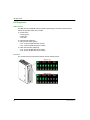
Modicon eX80
EAV16400 04/2014
Modicon eX80
BME AHI 0812 HART Analog Input
Module &
BME AHO 0412 HART Analog Output
Module
User Guide
EAV16400.01
04/2014
www.schneider-electric.com
The information provided in this documentation contains general descriptions and/or technical
characteristics of the performance of the products contained herein. This documentation is not
intended as a substitute for and is not to be used for determining suitability or reliability of these
products for specific user applications. It is the duty of any such user or integrator to perform the
appropriate and complete risk analysis, evaluation and testing of the products with respect to the
relevant specific application or use thereof. Neither Schneider Electric nor any of its affiliates or
subsidiaries shall be responsible or liable for misuse of the information contained herein. If you
have any suggestions for improvements or amendments or have found errors in this publication,
please notify us.
No part of this document may be reproduced in any form or by any means, electronic or
mechanical, including photocopying, without express written permission of Schneider Electric.
All pertinent state, regional, and local safety regulations must be observed when installing and
using this product. For reasons of safety and to help ensure compliance with documented system
data, only the manufacturer should perform repairs to components.
When devices are used for applications with technical safety requirements, the relevant
instructions must be followed.
Failure to use Schneider Electric software or approved software with our hardware products may
result in injury, harm, or improper operating results.
Failure to observe this information can result in injury or equipment damage.
© 2014 Schneider Electric. All rights reserved.
2
EAV16400 04/2014
Table of Contents
Safety Information . . . . . . . . . . . . . . . . . . . . . . . . . . . . .
About the Book. . . . . . . . . . . . . . . . . . . . . . . . . . . . . . . .
Chapter 1 Introducing the BME AHI 0812 and BME AHO 0412
eX80 HART Analog I/O . . . . . . . . . . . . . . . . . . . . . . . . . .
Adding HART eX80 Analog I/O to a Modicon X80 Network . . . . . . . .
Chapter 2 Installing HART Analog I/O Modules . . . . . . . . . . . . . .
Installing Analog I/O Modules . . . . . . . . . . . . . . . . . . . . . . . . . . . . . . .
Fitting a 20-Pin Terminal Block to an Analog I/O Module . . . . . . . . . .
20-Pin Terminal Blocks . . . . . . . . . . . . . . . . . . . . . . . . . . . . . . . . . . . .
How to Connect HART Analog Input/Output Modules: Connecting 20pin Terminal Block Modules . . . . . . . . . . . . . . . . . . . . . . . . . . . . . . . .
TELEFAST Wiring Accessories for the BME AHI 0812 and
BME AHO 0412 HART Analog Modules . . . . . . . . . . . . . . . . . . . . . . .
Chapter 3 LED Diagnostics . . . . . . . . . . . . . . . . . . . . . . . . . . . . . . .
LED Diagnostics . . . . . . . . . . . . . . . . . . . . . . . . . . . . . . . . . . . . . . . . .
eX80 Analog I/O Module Diagnostics . . . . . . . . . . . . . . . . . . . . . . . . .
Chapter 4 BME AHI 0812 HART Analog Input Module . . . . . . . . .
Physical Description . . . . . . . . . . . . . . . . . . . . . . . . . . . . . . . . . . . . . .
BME AHI 0812 Specifications . . . . . . . . . . . . . . . . . . . . . . . . . . . . . . .
Functional Description . . . . . . . . . . . . . . . . . . . . . . . . . . . . . . . . . . . . .
Using EMC Kits . . . . . . . . . . . . . . . . . . . . . . . . . . . . . . . . . . . . . . . . . .
Wiring Diagrams . . . . . . . . . . . . . . . . . . . . . . . . . . . . . . . . . . . . . . . . .
Using the TELEFAST ABE7-CPA02/03/31 Wiring Accessory. . . . . . .
Chapter 5 BME AHO 0412 HART Analog Output Module . . . . . . .
Physical Description . . . . . . . . . . . . . . . . . . . . . . . . . . . . . . . . . . . . . .
BME AHO 0412 Specifications . . . . . . . . . . . . . . . . . . . . . . . . . . . . . .
Functional Description . . . . . . . . . . . . . . . . . . . . . . . . . . . . . . . . . . . . .
Using EMC Kits . . . . . . . . . . . . . . . . . . . . . . . . . . . . . . . . . . . . . . . . . .
Wiring Diagrams . . . . . . . . . . . . . . . . . . . . . . . . . . . . . . . . . . . . . . . . .
Using the TELEFAST ABE7-CPA21 Wiring Accessory. . . . . . . . . . . .
Chapter 6 Ethernet Services . . . . . . . . . . . . . . . . . . . . . . . . . . . . . .
Fast Device Replacement . . . . . . . . . . . . . . . . . . . . . . . . . . . . . . . . . .
Upgrading Firmware . . . . . . . . . . . . . . . . . . . . . . . . . . . . . . . . . . . . . .
EAV16400 04/2014
7
9
11
11
13
14
17
21
24
27
29
30
31
33
34
35
37
41
44
50
55
56
57
59
62
64
67
69
70
71
3
Chapter 7 Introducing HART . . . . . . . . . . . . . . . . . . . . . . . . . . . . .
7.1
7.2
Introducing the HART Multiplexer . . . . . . . . . . . . . . . . . . . . . . . . . . . .
Introducing HART. . . . . . . . . . . . . . . . . . . . . . . . . . . . . . . . . . . . . . . . .
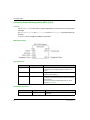
HART Multiplexer Communication . . . . . . . . . . . . . . . . . . . . . . . . . . . .
HART Multiplexer Commands . . . . . . . . . . . . . . . . . . . . . . . . . . . . . . .
Explicit Messaging Using the DATA_EXCH Block. . . . . . . . . . . . . . . .
Configuring Explicit Messaging Using DATA_EXCH . . . . . . . . . . . . . .
Configuring EtherNet/IP Explicit Messaging Using DATA_EXCH . . . .
Configuring the DATA_EXCH Management Parameter . . . . . . . . . . .
Configuring EtherNet/IP Explicit Messaging Using DATA_EXCH . . . .
Viewing the DATA_EXCH Received_Data Parameter. . . . . . . . . . . . .
Chapter 8 Configuring BME AHI 0812 and BME AHO 0412
Modules in Unity Pro . . . . . . . . . . . . . . . . . . . . . . . . . . .
8.1
8.2
Adding and Configuring HART Analog I/O. . . . . . . . . . . . . . . . . . . . . .
Creating a New M580 Project in Unity Pro. . . . . . . . . . . . . . . . . . . . . .
Adding HART Analog I/O Modules to the Project . . . . . . . . . . . . . . . .
Configuring Analog Input Channels for the BME AHI 0812 . . . . . . . . .
Configuring Analog Output Channels for the BME AHO 0412. . . . . . .
Configuring X80 Analog Device DDT Parameters . . . . . . . . . . . . . . . .
Device DDT Parameters for the BME AHI 0812 . . . . . . . . . . . . . . . . .
Device DDT Parameters for the BME AHO 0412 . . . . . . . . . . . . . . . .
Chapter 9 Configuring BME AHI 0812 and BME AHO 0412 DTMs
9.1
9.2
9.3
4
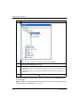
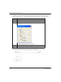
Adding a Module DTM . . . . . . . . . . . . . . . . . . . . . . . . . . . . . . . . . . . . .
Adding a DTM to the DTM Browser . . . . . . . . . . . . . . . . . . . . . . . . . . .
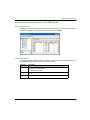
Configuring the Module IP Address . . . . . . . . . . . . . . . . . . . . . . . . . . .
Assigning IP Addressing Parameters. . . . . . . . . . . . . . . . . . . . . . . . . .
Configuring IP Address Settings . . . . . . . . . . . . . . . . . . . . . . . . . . . . .
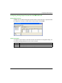
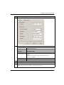
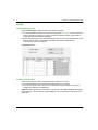
Configuring the Module DTM . . . . . . . . . . . . . . . . . . . . . . . . . . . . . . . .
FDT/DTM Configuration . . . . . . . . . . . . . . . . . . . . . . . . . . . . . . . . . . . .
Module Overview . . . . . . . . . . . . . . . . . . . . . . . . . . . . . . . . . . . . . . . . .
Address Table . . . . . . . . . . . . . . . . . . . . . . . . . . . . . . . . . . . . . . . . . . .
General Information . . . . . . . . . . . . . . . . . . . . . . . . . . . . . . . . . . . . . . .
Host Communication Status. . . . . . . . . . . . . . . . . . . . . . . . . . . . . . . . .
Instrument Status . . . . . . . . . . . . . . . . . . . . . . . . . . . . . . . . . . . . . . . . .
Multiplexer Status. . . . . . . . . . . . . . . . . . . . . . . . . . . . . . . . . . . . . . . . .
Process Data . . . . . . . . . . . . . . . . . . . . . . . . . . . . . . . . . . . . . . . . . . . .
75
76
77
79
81
83
84
86
87
88
89
91
92
93
94
97
99
101
102
103
105
106
106
110
111
112
115
116
117
118
119
122
123
125
127
EAV16400 04/2014
9.4
9.5
SNMP Configuration . . . . . . . . . . . . . . . . . . . . . . . . . . . . . . . . . . . . . .
Parameter Configuration . . . . . . . . . . . . . . . . . . . . . . . . . . . . . . . . . . .
Security . . . . . . . . . . . . . . . . . . . . . . . . . . . . . . . . . . . . . . . . . . . . . . . .
EIP Configuration . . . . . . . . . . . . . . . . . . . . . . . . . . . . . . . . . . . . . . . .
Completing the Project Configuration . . . . . . . . . . . . . . . . . . . . . . . . .
Manually Adding a Field Instrument DTM . . . . . . . . . . . . . . . . . . . . . .
Field Bus Discovery Service . . . . . . . . . . . . . . . . . . . . . . . . . . . . . . . .
Transferring the Configuration to the CPU . . . . . . . . . . . . . . . . . . . . .
Accessing Field Instrument Data in Unity Pro . . . . . . . . . . . . . . . . . . .
Working with Field Instrument Management Tools . . . . . . . . . . . . . . .
Working with FieldCare . . . . . . . . . . . . . . . . . . . . . . . . . . . . . . . . . . . .
Working with PACTware . . . . . . . . . . . . . . . . . . . . . . . . . . . . . . . . . . .
Chapter 10 Analog Module Debugging . . . . . . . . . . . . . . . . . . . . . .
Introducing the Debug Function of an Analog Module . . . . . . . . . . . .
Description of the Analog Module Debug Screen . . . . . . . . . . . . . . . .
Selecting the Adjustment Values for the Input Channels and
Measurement Forcing . . . . . . . . . . . . . . . . . . . . . . . . . . . . . . . . . . . . .
Modification of Output Channels Adjustment Values . . . . . . . . . . . . .
Chapter 11 Analog Module Diagnostics . . . . . . . . . . . . . . . . . . . . .
Diagnostics of an Analog Module . . . . . . . . . . . . . . . . . . . . . . . . . . . .
Detailed Diagnostics by Analog Channel . . . . . . . . . . . . . . . . . . . . . .
Chapter 12 IODDTs and Device DDTs . . . . . . . . . . . . . . . . . . . . . . .
Detailed Description of T_ANA_IN_BMX-type IODDT Objects . . . . . .
Detailed Description of T_ANA_OUT_BMX-type IODDT Objects . . . .
Detailed Description of T_ANA_IN_GEN-type IODDT Objects . . . . . .
Detailed Description of T_ANA_OUT_GEN-type IODDT Objects . . . .
Details of the Language Objects of the IODDT of Type T_GEN_MOD
Analog Device DDT . . . . . . . . . . . . . . . . . . . . . . . . . . . . . . . . . . . . . . .
Analog Device Ethernet Remote I/O Forcing Mode . . . . . . . . . . . . . .
Description of HART DDT Objects . . . . . . . . . . . . . . . . . . . . . . . . . . .
Chapter 13 Operating Modules from the Application . . . . . . . . . . .
13.1 Access to the Measurements and Statuses . . . . . . . . . . . . . . . . . . . .
Addressing of the Analog Module Objects . . . . . . . . . . . . . . . . . . . . .
Module Configuration . . . . . . . . . . . . . . . . . . . . . . . . . . . . . . . . . . . . .
EAV16400 04/2014
133
135
137
139
141
142
144
147
149
151
152
154
157
158
159
161
163
165
166
168
169
170
173
176
177
178
179
186
188
189
190
191
193
5
13.2
Additional Programming Features . . . . . . . . . . . . . . . . . . . . . . . . . . . .
Presentation of Language Objects Associated with the Analog
Modules . . . . . . . . . . . . . . . . . . . . . . . . . . . . . . . . . . . . . . . . . . . . . . . .
Implicit Exchange Language Objects Associated with Analog Modules
Explicit Exchange Language Objects Associated with Analog Modules
Management of Exchanges and Reports with Explicit Objects . . . . . .
Language Objects Associated with Configuration . . . . . . . . . . . . . . . .
Appendices . . . . . . . . . . . . . . . . . . . . . . . . . . . . . . . . . . . . . . . . .
Appendix A Topological/State RAM Addressing of the Modules . .
Topological/State RAM Addressing of Modicon M340 and X80 Analog
Modules . . . . . . . . . . . . . . . . . . . . . . . . . . . . . . . . . . . . . . . . . . . . . . . .
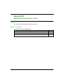
Appendix B EtherNet/IP Communication Codes . . . . . . . . . . . . . . .
Explicit Messaging: Communication and Operation Reports . . . . . . . .
CIP General Status Codes. . . . . . . . . . . . . . . . . . . . . . . . . . . . . . . . . .
EtherNet/IP Implicit or Explicit Messaging Detected Error Codes . . . .
Glossary . . . . . . . . . . . . . . . . . . . . . . . . . . . . . . . . . . . . . . . . .
Index . . . . . . . . . . . . . . . . . . . . . . . . . . . . . . . . . . . . . . . . .
6
197
198
199
200
203
207
211
213
213
215
216
219
222
225
233
EAV16400 04/2014
Safety Information
Important Information
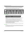
NOTICE
Read these instructions carefully, and look at the equipment to become familiar with the device
before trying to install, operate, or maintain it. The following special messages may appear
throughout this documentation or on the equipment to warn of potential hazards or to call attention
to information that clarifies or simplifies a procedure.
EAV16400 04/2014
7
PLEASE NOTE
Electrical equipment should be installed, operated, serviced, and maintained only by qualified
personnel. No responsibility is assumed by Schneider Electric for any consequences arising out of
the use of this material.
A qualified person is one who has skills and knowledge related to the construction and operation
of electrical equipment and its installation, and has received safety training to recognize and avoid
the hazards involved.
8
EAV16400 04/2014
About the Book
At a Glance
Document Scope
This manual describes the following eX80 HART analog I/O modules:
BME AHI 0812 input module
BME AHO 0412 output module
Validity Note
The eX80 HART analog I/O modules described in this manual require the use of Unity Pro version
8.0 or higher.
Product Related Information
WARNING
UNINTENDED EQUIPMENT OPERATION
The application of this product requires expertise in the design and operation of control systems.
Allow only authorized personnel with such expertise to program, install, alter, and apply this
product.
Follow all local and national safety codes and standards.
Failure to follow these instructions can result in death, serious injury, or equipment
damage.
EAV16400 04/2014
9
10
EAV16400 04/2014
Modicon eX80
Introduction
EAV16400 04/2014
Introducing the BME AHI 0812 and BME AHO 0412 eX80 HART Analog I/O
Chapter 1
Introducing the BME AHI 0812 and BME AHO 0412 eX80
HART Analog I/O
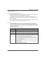
Adding HART eX80 Analog I/O to a Modicon X80 Network
Positioning BME AHI 0812 and BME AHO 0412 Modules in a Network
You can use the BME AHI 0812 input module and the BME AHO 0412 output module as:
local I/O in the main local Ethernet backplane
remote I/O modules in the main Ethernet rack of a remote I/O drop
NOTE: You can mount a HART analog eX80 I/O module only in the main segment of a local rack
or a remote I/O drop. You cannot mount a HART analog eX80 I/O module in a rack extension.
The BME AHI 0812 input module and the BME AHO 0412 output modules support the following
asset management software programs:
FieldCare Asset Management Software by Endress+Hauser
PACTware a free download from the PACTware Consortium
Local I/O
You can add up to 6 HART analog I/O modules to a main local rack. In addition to the I/O modules,
the local rack includes the following components:
a BME XBP xx00 rack
a BME P58 x0x0 CPU
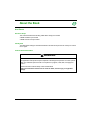
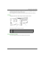
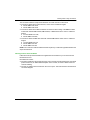
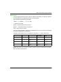
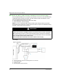
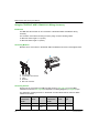
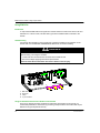
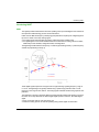
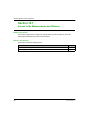
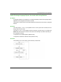
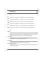
An example of a single local rack installation:
1
2
3
Local rack containing a BME P58 3040 CPU, power supply, and 6 I/O modules
Maintenance PC, operating as HART primary master, connected to the local rack via Ethernet copper cable
HART field instruments connected to I/O via 4-20 mA current loop wiring
EAV16400 04/2014
11
Introduction
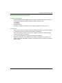
Remote I/O
You can add up to 7 HART analog I/O modules to the main rack of a remote I/O drop. In addition
to the I/O modules, the remote I/O rack includes the following components:
a BME XBP xx00 rack
a BME CRA 312 10 adapter
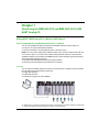
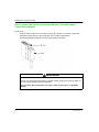
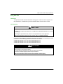
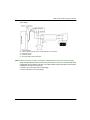
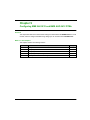
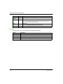
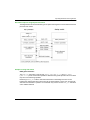
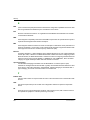
An example of a single local rack with a remote I/O drop:
1
2
3
4
5
12
Local rack containing a BME P58 3040 CPU, power supply, and 6 I/O modules
Remote drop containing a BME CRA 312 10 adapter and 7 I/O modules
HART field instruments connected to I/O via 4-20 mA current loop wiring
Maintenance PC, operating as HART primary master, connected to the local rack via Ethernet copper cable
Remote I/O main ring
EAV16400 04/2014
Modicon eX80
Installing HART Analog I/O Modules
EAV16400 04/2014
Installing HART Analog I/O Modules
Chapter 2
Installing HART Analog I/O Modules
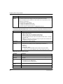
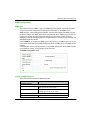
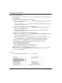
Overview
This chapter describes the installation of the HART analog I/O modules, including:
mounting the module on the backplane
fitting a 20-pin terminal block to the module
connecting 20-pin terminal blocks
selecting TELEFAST wiring accessories
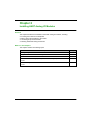
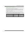
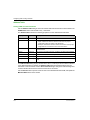
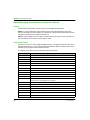
What Is in This Chapter?
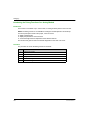
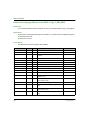
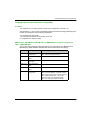
This chapter contains the following topics:
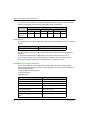
Topic
Page
Installing Analog I/O Modules
14
Fitting a 20-Pin Terminal Block to an Analog I/O Module
17
20-Pin Terminal Blocks
21
How to Connect HART Analog Input/Output Modules: Connecting 20-pin Terminal Block
Modules
24
TELEFAST Wiring Accessories for the BME AHI 0812 and BME AHO 0412 HART Analog
Modules
27
EAV16400 04/2014
13
Installing HART Analog I/O Modules
Installing Analog I/O Modules
At a Glance
The analog I/O modules are powered by the rack bus. The modules may be installed and
uninstalled without turning off power supply to the rack.
Fitting operations (installation, assembly, and disassembly) are described below.
Before Installing a Module
Before installing a module, take off the protective cap from the module connector located on the
rack.
DANGER
HAZARD OF ELECTRIC SHOCK, EXPLOSION, OR ARC FLASH
Before mounting / removing the modules:
confirm that the terminal block is still connected to the shield bar
disconnect the voltage of sensors and pre-actuators
Failure to follow these instructions will result in death or serious injury.
NOTE: Modules are calibrated at the factory before being shipped.
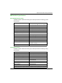
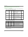
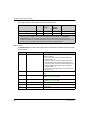
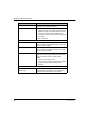
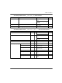
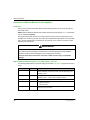
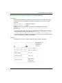
Selecting a Backplane
Install the analog I/O modules on one of the following Ethernet backplanes:
Backplane
BME XBP 0400
Description
1
4-slot Ethernet backplane
BME XBP 0400(H)1
4-slot hardened Ethernet backplane
BME XBP 08001
8-slot Ethernet backplane
BME XBP 0800(H)1
8-slot hardened Ethernet backplane
BME XBP 12001, 2
12-slot Ethernet backplane
BME XBP 1200(H)1, 2
12-slot hardened Ethernet backplane
1. The following reserved slots are not available for module installation:
In a local rack, slots 0 and 1 are reserved for the CPU.
In a remote I/O drop, slot 0 is reserved for a BME CRA 312 10 adapter module.
2. The following reserved slots are not available for module installation: slots 2, 8, 10 and 11,
which are reserved for gateway communication modules.
14
EAV16400 04/2014
Installing HART Analog I/O Modules
The HART analog modules may be installed in any of the slots in the backplane except for the
reserved slots described in the table footnotes, above.
Power is supplied to the I/O modules by the bus at the bottom of the rack (3.3 V and 24 V).
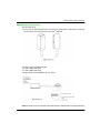
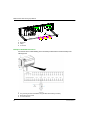
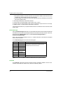
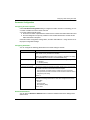
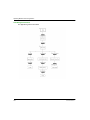
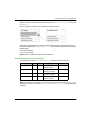
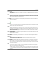
Installation
The diagram below shows a HART analog I/O module mounted on the rack.
The assembly includes the following components:
Number
Description
1
20-pin terminal block module
2
8 slot Ethernet backplane
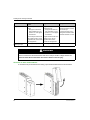
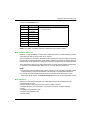
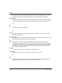
Installing the Module on the Rack
To mount the analog I/O modules on the backplane, follow these steps:
EAV16400 04/2014
15
Installing HART Analog I/O Modules
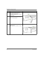
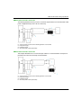
Step
16
Action
Illustration
1
Position the locating pins situated at the rear of
the module (on the bottom part) in the
corresponding slots in the rack.
Note: Before positioning the pins, remove the
protective cover.
Steps 1 and 2
2
Swivel the module towards the top of the rack so
that the module sits flush with the back of the
rack. It is now set in position.
3
Tighten the retaining screw to hold the module in Step 3
place on the rack.
Tightening torque: 1.5 N•m max. (1.11 lb-ft)
EAV16400 04/2014
Installing HART Analog I/O Modules
Fitting a 20-Pin Terminal Block to an Analog I/O Module
At a Glance
Both the BME AHI 0812 and BME AHO 0412 modules need to be connected to a 20-pin terminal
block. The process of fitting a block to a module is described below.
CAUTION
EQUIPMENT DAMAGE
Do not plug an AC terminal block on a DC module. This can cause equipment damage.
Failure to follow these instructions can result in injury or equipment damage.
Installing the 20-Pin Terminal Block
To fit the 20-pin terminal block onto the BME AHI 0812 and BME AHO 0412 HART analog
modules, follow these steps:
Step
Action
1
After the module has been placed onto the rack, install the terminal block by
inserting the rear lower part of the terminal into the front lower part of the
module, as shown above.
2
Affix the terminal block to the module by tightening the 2 mounting screws
located on the lower and upper parts of the terminal block.
NOTE: Apply a tightening torque of 0.4 N•m (0.30 lb-ft).
NOTE: If the screws are not tightened, the terminal block may not be properly affixed to the
module.
EAV16400 04/2014
17
Installing HART Analog I/O Modules
Coding the 20-Pin Terminal Block
When installing a 20-pin terminal block on a BME AHI 0812 or BME AHO 0412 module, you can
code the terminal block so that it may be used only with a particular module. To do this, apply studs
to both the terminal block and to the module in a pattern so that the 2 components fit each other,
but do not fit other modules or terminal blocks. In this way, you can reduce the likelihood that a
terminal block will be mounted on a module other than the intended module.
To perform coding, use the studs on the STB XMP 7800 guidance wheel. You can insert studs in
the 6 guidance slots on the left side of the module, and in the corresponding 6 slots in the terminal
block.
To fit the terminal block to the module:
a module slot with a stud corresponds to an empty slot in the terminal block, and
a terminal block slot with a stud corresponds to an empty slot in the module
The following diagram depicts a guidance wheel and the slots on the module used for coding the
20-pin terminal blocks:
18
EAV16400 04/2014
Installing HART Analog I/O Modules
The following example depicts a coding configuration that allows a terminal block to fit together with
a module:
The following example depicts a coding configuration that obstructs the terminal block from fitting
onto the module:
EAV16400 04/2014
19
Installing HART Analog I/O Modules
DANGER
ELECTRICAL SHOCK
Connect or disconnect the terminal block with sensor and pre-actuator voltage switched off.
Failure to follow these instructions will result in death or serious injury.
NOTICE
POTENTIAL MODULE DAMAGE
Code the terminal block as described above to help prevent the terminal block from being
mounted on an incorrect module. Mounting a terminal block on an incorrect module may damage
the module.
Plugging the wrong connector could cause the module to be destroyed.
Failure to follow these instructions can result in equipment damage.
CAUTION
UNEXPECTED BEHAVIOR OF APPLICATION
Code the terminal block as described above to help prevent the terminal block from being
mounted on another module.
Plugging the wrong connector could cause unexpected behavior of the application.
Failure to follow these instructions can result in injury or equipment damage.
NOTE: The module connector has indicators that show the proper direction for inserting studs into
a terminal block installation.
20
EAV16400 04/2014
Installing HART Analog I/O Modules
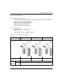
20-Pin Terminal Blocks
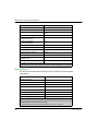
Identifying 20-Pin Terminal Blocks
The BME AHI 0812 and BME AHO 0412 modules are supplemented by a 20-pin terminal block.
There are 3 types of 20-pin terminal blocks:
BMX FTB 2010 screw clamp terminal blocks
BMX FTB 2000 caged terminal blocks
BMX FTB 2020 spring terminal blocks
Cable Ends and Contacts
Each terminal block can accommodate:
Bare wires
Wires with DZ5-CE type
cable ends
Description of the 20-Pin Terminal Blocks
Screw Clamp Terminal
Blocks
Caged Terminal Blocks
Spring Terminal Blocks
2
1
1
Illustration
Number of wires
accommodated
Number of minimum AWG 24 (0.34 mm2)
wire gauges
maximum AWG 16 (1.5 mm2)
accommod
ated
EAV16400 04/2014
21
Installing HART Analog I/O Modules
Wiring constraints
Maximum screw
tightening torque
Screw Clamp Terminal
Blocks
Caged Terminal Blocks
Spring Terminal Blocks
Screw clamps have slots that
accept:
flat-tipped screwdrivers
with a diameter of 5 mm
posidriv n°1 cross-tipped
screwdrivers
Caged terminal blocks have
slots that accept:
flat-tipped screwdrivers
with a diameter of 3 mm
posidriv n°1 cross-tipped
screwdrivers
The wires are connected by
pressing the button located
next to each pin.
To press the button, use a
flat-tipped screwdriver with a
maximum diameter of 3 mm.
Screw clamp terminal blocks
have captive screws. On the
supplied blocks, these screws
are not tightened.
Caged terminal blocks have
captive screws. On the
supplied blocks, these
screws are not tightened.
0.5 N•m (0.37 lb-ft)
0.5 N•m (0.37 lb-ft)
–
DANGER
ELECTRICAL SHOCK
Connect or disconnect the terminal block with sensor and pre-actuator voltage switched off.
Failure to follow these instructions will result in death or serious injury.
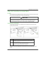
Connection of 20-Pin Terminal Blocks
To access the 20-pin terminal block for wiring, open the terminal block door as shown below:
22
EAV16400 04/2014
Installing HART Analog I/O Modules
The connection cables for 20-pin terminal blocks come with 3 kinds of connections:
Connection cables with an FTB connector, which come in 2 different lengths:
3 meter: BMX FTW 301S
5 meter: BMX FTW 501S
Connection cables with FTB and D-Sub25 connectors for direct wiring of the BME AHI 0812
module with Telefast ABE7CPA02, ABE7CPA03, or ABE7CPA31 which come in 2 different
lengths:
1.5 meter: BMX FTA 1522,
3 meter: BMX FTA 3022,
Connection cables for BME AHO 0412 with Telefast ABE7CPA21 which come in 3 different
lengths:
1.5 meter: BMX FCA 150
3 meter: BMX FCA 300
5 meter: BMX FCA 500
NOTE: The connection cable is installed and held in place by a cable clamp positioned below the
20-pin terminal block.
Labeling of 20-Pin Terminal Blocks
Labels for the 20-pin terminal blocks are supplied with the module that you can insert into the
terminal block cover.
Each label has 2 sides:
One side is visible from the outside when the cover is closed. This side features the commercial
product references, an abbreviated description of the module, as well as a blank section for
customer labeling.
One side is visible from the inside when the cover is open. This side shows the terminal block
connection diagram.
EAV16400 04/2014
23
Installing HART Analog I/O Modules
How to Connect HART Analog Input/Output Modules: Connecting 20-pin
Terminal Block Modules
Introduction
20-pin connector modules are connected to sensors, pre-actuators or terminals using a cable
designed to enable direct wire to wire transition of the module’s inputs/outputs.
The following diagram shows the connection of the cable to the module:
WARNING
UNEXPECTED EQUIPMENT OPERATION
Use only a connector that is designed for a specific module. Plugging the wrong connector can
cause an unexpected behavior of the application.
Failure to follow these instructions can result in death, serious injury, or equipment
damage.
24
EAV16400 04/2014
Installing HART Analog I/O Modules
BMX FTW ••1S Connection Cables
They are made up of:
At one end, a compound-filled 20-pin connector from which extend 1 cable sheath, containing
20 wires with a cross-sectional area of 0.34 mm2 (AWG 24),
At the other end, free wire ends differentiated by color code.
The cable comes in 2 different lengths:
3 meters: BMX FTW 301S;
5 meters: BMX FTW 501S;
The figure below shows the BMX FTW ••1S cables:
NOTE: A strand of nylon incorporated in the cable allows the cable sheath to be stripped with ease.
EAV16400 04/2014
25
Installing HART Analog I/O Modules
NOTE: Switch off sensor and pre-actuator voltage before connecting or disconnecting the 20-pin
connectors.
Connection of BMX FTW ••1S Cables
The diagram below shows the connection of BMX FTW ••1S cable:
26
EAV16400 04/2014
Installing HART Analog I/O Modules
TELEFAST Wiring Accessories for the BME AHI 0812 and BME AHO 0412 HART
Analog Modules
Overview
The following TELEFAST wiring accessories are available for the HART I/O modules:
For the BME AHI 0812 8-channel analog input module:
ABE7-CPA02: 8-channel TELEFAST wiring accessory
ABE7-CPA03: 8-channel TELEFAST wiring accessory with non-isolated 24Vdc/25mA power
supplies
ABE7-CPA31: 8-channel TELEFAST wiring accessory with isolated 24Vdc/25mA power
supplies
For the BME AHO 0412 4-channel analog output module:
ABE7-CPA21: 4-channel TELEFAST wiring accessory
Illustration
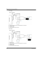
The HART analog module may be connected to the TELEFAST accessories using a 5-, 3-, or 1.5meter shielded cable:
EAV16400 04/2014
27
Installing HART Analog I/O Modules
1: HART Analog I/O
2: Cable
3: TELEFAST Wiring Accessory
BME AHI 0812
BMX FTA 1522: 1.5 m shielded cable
BMX FTA 3022: 3 m shielded cable
Any one of:
ABE7-CPA02
ABE7-CPA03
ABE7-CPA31
BMX FCA 150: 1.5 m shielded cable
ABE7-CPA21
BME AHO 0412
BMX FCA 300: 3 m shielded cable
BMX FCA 500: 5 m shielded cable
28
EAV16400 04/2014
Modicon eX80
LED Diagnostics
EAV16400 04/2014
LED Diagnostics
Chapter 3
LED Diagnostics
Overview
This chapter describes how to use module LEDs to diagnose the BME AHI 0812 and
BME AHO 0412 HART analog I/O.
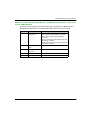
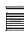
What Is in This Chapter?
This chapter contains the following topics:
Topic
Page
LED Diagnostics
30
eX80 Analog I/O Module Diagnostics
31
EAV16400 04/2014
29
LED Diagnostics
LED Diagnostics
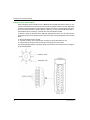
LED Indicators
The BME AHI 0812 and BME AHO 0412 HART eX80 analog I/O modules include LEDs that
indicate the operating status of the module:
module status:
RUN (green)
ERR (red)
I/O (red)
bus status: BS (red/green)
analog channel status (green):
A0...A7 (for the BME AHI 0812 module)
A0...A3 (for the BME AHO 0412 module)
HART channel status (red/green):
H0...H7 (for the BME AHI 0812 module)
H0...H3 (for the BME AHO 0412 module)
Illustration
The modules have several LEDs that indicate module operating status:
30
EAV16400 04/2014
LED Diagnostics
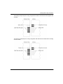
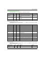
eX80 Analog I/O Module Diagnostics
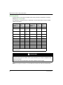
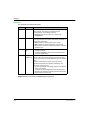
LED Diagnostics
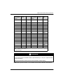
Use the combined states of the RUN, ERR, I/O, BS, An and Hn LEDs to diagnose the channel and
module status for the BME AHI 0812 and BME AHO 0412 modules:
LED
RUN
Description
ERR
I/O
BS
A0...An
H0...Hn
OFF
OFF
OFF
OFF
All OFF
All OFF
Module has no power, or has stopped operating.
BLK
green
BLK
red
BLK
red
BLK red
& green
All OFF
All OFF
Module is performing self-test on power-up.
OFF
BLK
red
OFF
X
All OFF
All OFF
The module is not yet configured, or is in the process
of configuring its channels.
ON
green
BLK
red
X1
X
X
X
No communication between the output module and
the head module.
NOTE: The module retains the previous I/O status.
ON
green
OFF
OFF
X
ON green
X
Analog channel is operational.
ON
green
OFF
OFF
X
OFF
X
Analog channel is disabled.
ON
green
ON
red
OFF
X
OFF
X
Analog to digital conversion detected error, or power
supply detected error on channel.
ON
green
OFF
ON red X
FLK
X
Overflow or underflow error detected on channel.
ON
green
OFF
ON red X
BLK
X
Broken wired detected on input sensor channel or
output actuator channel.
ON
green
OFF
ON red X
OFF
X
Calibration error detected on output channel.
ON
green
OFF
ON red X
X
ON red
No response from HART device on channel.
ON
green
OFF
OFF
X
X
BS red
A HART device has been detected with a major
difference from the device that is configured for the
channel.
ON
green
OFF
OFF
X
X
FLK red
A HART device has been detected with a minor
difference from the device that is configured for the
channel.
ON
green
OFF
OFF
X
X
ON
green
A HART device has been detected that is the same as
the device configured for the channel, or a device with
a detected major or minor difference has been
accepted.
EAV16400 04/2014
31
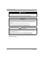
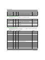
LED Diagnostics
LED
Description
RUN
ERR
I/O
BS
A0...An
H0...Hn
ON
green
OFF
OFF
X
X
BLK
green
The HART channel is connecting to a device.
ON
green
OFF
OFF
X
X
OFF
HART communication disabled for the channel.
BLK
green
OFF
OFF
BLK
green
X
X
The I/O module is downloading firmware.
X
X
X
OFF
X
X
The module has not been assigned an IP address.
X
X
X
BLK
green
X
X
The module has no established EIP Forward Open
connections, but has an IP address.
X
X
X
ON
green
X
X
The module has established an Ethernet connection.
X
X
X
BLK red
X
X
The module Ethernet connection has timed out. This
is cleared only when the timed out connection is reestablished or if the module is reset.
OFF
X
X
ON red
X
X
The module has detected that its IP address is
already in use.
ON LED is steady on.
OFF LED is off.
FLK Flickering: ON for 50 ms, OFF for 50 ms, repeat.
BLK Blinking: ON for 200 ms, OFF for 200 ms, repeat.
BS Blinking Sequence: ON for 200 ms, OFF for 1,200 ms, repeat.
X This LED is not used in determining the channel or module status.
32
EAV16400 04/2014
Modicon eX80
BME AHI 0812 HART Analog Input Module
EAV16400 04/2014
BME AHI 0812 HART Analog Input Module
Chapter 4
BME AHI 0812 HART Analog Input Module
Overview
This chapter describes the BME AHI 0812 HART analog input module for eX80 platforms, and
shows you how to connect it to input sensors.
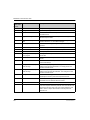
What Is in This Chapter?
This chapter contains the following topics:
Topic
Page
Physical Description
34
BME AHI 0812 Specifications
35
Functional Description
37
Using EMC Kits
41
Wiring Diagrams
44
Using the TELEFAST ABE7-CPA02/03/31 Wiring Accessory
50
EAV16400 04/2014
33
BME AHI 0812 HART Analog Input Module
Physical Description
Analog plus HART Communication
The BME AHI 0812 module is a high-density input module that includes 8 isolated analog
channels. Each channel supports HART digital communication.
Use the module with sensors or transmitters. The module uses a 4-20 mA analog signal to perform
monitoring and measurement functions.
The module also supports the HART protocol, which superimposes a digital signal on top of the
analog signal. The HART digital signal communicates additional instrument information including
instrument status, additional process variables, configuration data, and diagnostics.
Illustration
The BME AHI 0812 analog input module with a 20-pin terminal block accessory:
1
2
LED display
20-pin terminal block accessory
NOTE: The terminal block accessory is supplied separately.
34
EAV16400 04/2014
BME AHI 0812 HART Analog Input Module
BME AHI 0812 Specifications
General Module Specifications
The BME AHI 0812 eX80 HART analog input module possesses the following general
characteristics:
Head module compatibility
Isolation:
between channels
Local rack: BME P58 x0x0 CPU
Remote I/O drop: BME CRA 312 10 adapter
–
1000 Vdc (1 minute duration)
between channels and bus
1400 Vdc (1 minute duration)
between channels and ground
1400 Vdc (1 minute duration)
Operating altitude
0...4000 m
Operating ambient temperature
0...60° C
Vibration
10 mm / 3 g / x10 (per IEC60068-2-6)
Shock
30 g / 11 ms / x3 (per IEC60068-2-27)
Power consumption (3.3V)
0.4 A
Power consumption (24V)
0.04 A
Field device support
2-wire / 4-wire
Maximum overload authorized for inputs
Hot-swap support?
Voltage: +/– 30 Vdc
Current: +/– 90 mA
Yes
Analog Specifications
The BME AHI 0812 eX80 HART analog input module possesses the following analog
characteristics:
Number of channels
8
Type of inputs
High-density isolated fast inputs
Nominal range (full scale)
4-20 mA
Maximum conversion range
0.16...29.92 mA
Measurement accuracy for module:
–
Accuracy at 25° C
0.15% of full scale1
Accuracy at 0...60° C
0.3% of full scale1
Temperature drift
50 ppm / ° C
Display resolution
15-bit plus sign bit
1. Includes conversion resistor detected error.
2. Refresh times are for only the module internal buffer, and are impacted by PLC cycle time.
EAV16400 04/2014
35
BME AHI 0812 HART Analog Input Module
Least significant bit weight
0.458 µA
Refresh time:
–
per module
4 ms2
per channel
4 ms2
Response time:
–
with HART enabled
(without digital filter)
50 ms
with HART disabled
(without digital filter)
4 ms
Input impedance
250 Ω
Detection type
broken wire
Monotonicity?
Yes
Crosstalk between channels
≥80 dB
Non-linearity
0.02% of full scale
Repeatability at 25° C of 10 minutes
stabilization time
0.01% of full scale
Digital filtering
1st order
1. Includes conversion resistor detected error.
2. Refresh times are for only the module internal buffer, and are impacted by PLC cycle time.
HART Specifications
The BME AHI 0812 eX80 HART analog input module possesses the following HART
characteristics:
HART protocols supported2
HART versions 5, 6 and 7
Number of channels
8
Scan time:
–
Typical
1s
Maximum1
5s
1
Detection time for a non-responsive device = (scan time) + (timeouts)
HART command system
ARCOM (interface to a HART master)
Topology
Point-to-point
HART I/O mapping?
Yes
1. Scan time is the same for each channel and for the module. The scan time depends on
the byte length of the command. The scan time values do not include PLC cycle time, which
should be added to determine overall scan time.
2. The eX80 HART input module supports HART up to versions 7.2 and 7.3.
36
EAV16400 04/2014
BME AHI 0812 HART Analog Input Module
Functional Description
Introduction
The BME AHI 0812 eX80 HART analog input module supports 4-20 mA analog communication
and HART digital communication on each of 8 input channels. The module operates with voltage
inputs and includes 8 read resistors connected to the terminal block to convert current inputs.
The eX80 HART analog input module is powered by the backplane.
NOTE: The backplane does not provide power to the 4-20 mA current loop or to any sensor,
transmitter, or other device connected to the current loop. You need to provide a source of 24 Vdc
power to the current loop, as described in the wiring topic.
Measurement Timing
The BME AHI 0812 eX80 HART analog input module measurement refresh rate is 4 ms. This
refresh rate remains constant, no matter how many channels are enabled (or disabled).
NOTE: The module measurement refresh task is not synchronized with the PLC scan. Therefore,
you need to include the PLC scan time when estimating an overall application refresh rate.
Overflow/Underflow Control
Each input on the BME AHI 0812 eX80 HART analog input module operates over a range of 420 mA. You can use Unity Pro to map up to 5 current ranges (see page 97) for each input.
Upper and lower tolerance detections are enabled regardless of overflow/underflow control.
Depending on the range specified, the module checks for overflow and verifies that the
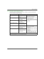
measurement falls between a lower and an upper threshold:
Designation
Description
Nominal range
The specified measurement range
Upper tolerance area
The range of values between the maximum value for the
nominal range (20 mA) and the upper threshold
Lower tolerance area
The range of values between the minimum value for the
nominal range (4 mA) and the lower threshold
Overflow area
The range of values located above the upper threshold
Underflow area
The range of values located below the lower threshold
EAV16400 04/2014
37
BME AHI 0812 HART Analog Input Module
NOTE: Monitoring of values in the overflow and underflow area can be enabled or disabled in Unity
Pro. Monitoring of the lower and upper tolerance areas is enabled and cannot be disabled.
The values of the thresholds are configurable independently from one another. Both the default
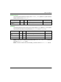
values, and the maximum and minimum configurable values are as follows:
Range
BME AHI 0812 Range
Underflow Area
Lower Tolerance
Area
Nominal Range
Upper Tolerance
Area
Overflow Area
Default
setting
–2,400
–800
–1
0
10,000
10,001
10,800
10,801
16,200
Minimum /
Maximum
–32,768 ...
...
...
...
...
...
...
...
32,767
–801
Measurement Display
Measurements may be displayed using the standard format (in %, to 2 decimal places):
Type of Range
Display
4-20 mA
from 0 to 10,000 (0% to 100%)
It is also possible to define the range of values within which measurements are expressed, by
selecting:
the minimum nominal value corresponding to the minimum value for the range: 0 %.
the maximum nominal value corresponding to the maximum value for the range (100 %).
The lower and upper thresholds can be integers between –32,768 and +32,767.
For example, imagine a conditioner providing pressure data on a 4-20 mA loop, with 4 mA
corresponding to 3,200 millibar and 20 mA corresponding to 9,600 millibar. You have the option of
choosing the format, by setting the following lower and upper thresholds:
3,200 for 3,200 millibar as the lower threshold
9,600 for 9,600 millibar as the upper threshold
In this case, values transmitted to the program vary between 3,200 (= 4 mA) and 9,600 (= 20 mA).
HART Filtering
When the HART function is enabled for the channel, the HART signal is filtered by the low pass
filter in the BME AHI 0812 eX80 HART analog input module before being read by the analog input.
The 3 dB cut-off frequency is about 10.0 Hz.
38
EAV16400 04/2014
BME AHI 0812 HART Analog Input Module
Digital Filtering
The type of filtering performed by the system is called first order filtering. The filtering coefficient
can be modified from a programming console or via the program.
The mathematical formula used is as follows:
Measf ( n ) D u Measf ( n - 1) (1- D) u Valb ( n )
α = efficiency of the filter
Measf(n) = measurement filtered at moment n
Measf(n-1) = measurement filtered at moment n-1
Valb(n) = gross value at moment n
You may configure the filtering value from 7 possibilities (from 0 to 6). This value may be changed
even when the application is in RUN mode.
The filtering values depend on the T configuration cycle (where T = module refresh time):
Corresponding α
Desired Efficiency
Required Value
Filter Response
Time at 63%
Cut-Off Frequency
(in Hz)
No filtering
0
0
0
0
Low filtering
1
2
0.750
0.875
4xT
8xT
0.040 / T
0.020 / T
Medium filtering
3
4
0.937
0.969
16 x T
32 x T
0.010 / T
0.005 / T
High filtering
5
6
0.984
0.992
64 x T
128 x T
0.0025 / T
0.0012 / T
NOTE: When HART communication is enabled, operation of both the HART filter and the digital
filter may cause excessive latency.
EAV16400 04/2014
39
BME AHI 0812 HART Analog Input Module
Sensor Alignment
The process of alignment involves the elimination of an observed systematic offset, around a
specific operating point, for a given sensor. Sensor alignment compensates for a detected variation
that is linked to the process. Replacing a module does not require a new alignment. However,
replacing the sensor or changing the sensor operating point requires a new alignment.
Conversion lines are as follows:
The alignment value is editable from a programming console, even if the program is in RUN mode.
For each input channel, you can:
view and modify the desired measurement value
save the alignment value
determine whether the channel already has an alignment
The alignment offset may also be modified through programming.
Channel alignment is performed on the channel in standard operating mode, without any effect on
the channel operating modes.
The maximum offset between measured value and desired (aligned) value may not exceed +/1,500.
NOTE: To align multiple analog channels on the BME AHI 0812 eX80 HART analog input module,
proceed channel by channel, aligning one channel at a time. Test each channel after aligning it
before proceeding to align the next channel.
40
EAV16400 04/2014
BME AHI 0812 HART Analog Input Module
Using EMC Kits
Introduction
To help shield the BME AHI 0812 eX80 HART analog input module from electro-magnetic and
radio interference, use EMC kits to ground the shielded cables connected to the module.
Cable Shielding
CAUTION
UNEXPECTED BEHAVIOR OF APPLICATION
To reduce electromagnetic perturbations, use a BMX XSP 0400/0800/1200 EMC kit to connect
the shielding.
Electromagnetic perturbations may lead to an unexpected behavior of the application.
Failure to follow these instructions can result in injury or equipment damage.
Connect the cable shielding to the grounding bar. Clamp the shielding to the grounding bar on the
module side. Use the following EMC kits to make these connections:
BMX XSP 0400 EMC kit, for use with the BME XBP 0400 rack
BMX XSP 0800 EMC kit, for use with the BME XBP 0800 rack
BMX XSP 1200 EMC kit, for use with the BME XBP 1200 rack
DANGER
HAZARD OF ELECTRIC SHOCK, EXPLOSION, OR ARC FLASH
While mounting / removing the modules:
Confirm that each terminal block is still connected to the shield bar.
Disconnect voltage supplying sensors and pre-actuators.
Failure to follow these instructions will result in death or serious injury.
EAV16400 04/2014
41
BME AHI 0812 HART Analog Input Module
1
3
2
4
1
2
3
4
BME AHI 0812
Shield bar
Clamp
To sensors
Example of TELEFAST Connection
Connect the sensor cable shielding to the terminals provided and the whole assembly to the
cabinet ground.
1
2
3
4
42
TELEFAST ABE7-CPA02
The grounding of cables is facilitated using the ABE7-CPA02 wiring accessory
Shield wiring to the ground
To current sensors
EAV16400 04/2014
BME AHI 0812 HART Analog Input Module
Reference of Sensors in Relation to the Ground
In order for the acquisition system to operate correctly, it is recommended to consider taking the
following steps:
place sensors close together (not more than a few meters apart)
reference each sensor to a single point, which is connected to the protective ground
Using the Sensors Referenced in Relation to the Ground
The sensors are connected as indicated in the following diagram:
If the sensors are referenced in relation to the ground, this can return a remote ground potential to
the terminal block. To help avoid this situation, follow these rules:
The potential needs to be less than the permitted low voltage of ± 500 Vdc.
Setting a sensor point to a reference potential generates a leakage current. Check that leakage
currents generated do not disturb the system.
NOTE: Sensors and other peripherals may be connected to a grounding point some distance from
the module. Such remote ground references may carry considerable potential differences with
respect to local ground. Induced currents do not affect the measurement or integrity of the system.
DANGER
HAZARD OF ELECTRIC SHOCK
Confirm that sensors and other peripherals are not exposed through grounding points to voltage
potential greater than acceptable limits.
Failure to follow these instructions will result in death or serious injury.
EAV16400 04/2014
43
BME AHI 0812 HART Analog Input Module
Wiring Diagrams
Point-to-Point Connections
The BME AHI 0812 eX80 HART analog input module supports point-to-point 4-20 mA wiring
connections to field instruments, including sensors and transmitters. You can make the connection
to the input module using a BMX FTB 20x0 20-pin terminal block, or a TELEFAST cable (which
includes a 20-pin terminal block).
The input module does not provide 4-20 mA current loop power. You need to include an external
power supply in your network that can provide current loop power.
Input Module Pinout
The BME AHI 0812 eX80 HART analog input module present the following 20-pin design, to which
you can connect a terminal block or TELEFAST cable:
44
EAV16400 04/2014
BME AHI 0812 HART Analog Input Module
BME AHI 0812 with 2-Wire Transmitter
The following illustration shows you how to connect the input module to a 2-wire transmitter. Field
power is supplied directly to the 4-20 mA current loop:
1
2
3
4
5
2-wire transmitter
4-20 mA current loop, with arrows indicating direction of current flow
Field power supply
Protective ground
Secondary HART master (hand-held)
BME AHI 0812 with 4-Wire Transmitter
This example illustrates how to connect the input module to a 4-wire transmitter. Field power is
provided to the 4-20 mA current loop via the transmitter:
1
2
3
4
5
4-wire transmitter
4-20 mA current loop, with arrows indicating direction of current flow
Field power supply
Protective ground
Secondary HART master (hand-held)
EAV16400 04/2014
45
BME AHI 0812 HART Analog Input Module
BME AHI 0812 with 2-Wire or 4-Wire Transmitter, TELEFAST Connector with Power Supply
These examples illustrate how to connect the input module to a 2-wire or 4-wire transmitter using
a TELEFAST wiring accessory and cable. The cable includes a 20-pin terminal block. 24 Vdc
power is supplied to the 4-20 mA current loop:
via the TELEFAST wiring accessory in the 2-wire design
via the transmitter in the 4-wire design
NOTE: If you use a TELEFAST ABE7-CPA03 or ABE7-CPA31 wiring accessory to provide 420 mA power to the current loop, connect only the ISx and the ICx pins on the TELEFAST wiring
accessory. The 0Vx pins are not connected.
DANGER
HAZARD OF ELECTRIC SHOCK
Isolation of the channels on the BME AHI 0812 is not preserved when you use the TELEFAST
ABE7-CPA03 wiring accessory. Confirm that the protective ground of sensors or transmitters
across all the channels are at ground potential. If the electrical potential of sensors or transmitters
varies, use ABE7-CPA31 instead of ABE7-CPA03.
Failure to follow these instructions will result in death or serious injury.
2-wire design:
1
2
3
4
5
46
2-wire transmitter
4-20 mA current loop, with arrows indicating direction of current flow
24 Vdc power supply
Protective ground
Secondary HART master (hand-held)
EAV16400 04/2014
BME AHI 0812 HART Analog Input Module
4-wire design:
1
2
3
4
5
4-wire transmitter
4-20 mA current loop, with arrows indicating direction of current flow
Field power supply
Protective ground
Secondary HART master (hand-held)
BME AHI 0812 with 2-Wire or 4-Wire Transmitter, TELEFAST Connector without Power Supply
These examples illustrate how to connect the input module to a 2-wire or 4-wire transmitter using
a TELEFAST wiring accessory and cable. The cable includes a 20-pin terminal block. Field power
is supplied to the 4-20 mA current loop:
directly to the current loop in the 2-wire design
via the transmitter in the 4-wire design
EAV16400 04/2014
47
BME AHI 0812 HART Analog Input Module
2-wire design:
1
2
3
4
5
2-wire transmitter
4-20 mA current loop, with arrows indicating direction of current flow
Field power supply
Protective ground
Secondary HART master (hand-held)
4-wire design:
1
2
3
4
5
48
4-wire transmitter
4-20 mA current loop, with arrows indicating direction of current flow
Field power supply
Protective ground
Secondary HART master (hand-held)
EAV16400 04/2014
BME AHI 0812 HART Analog Input Module
HART Network Cable Characteristics and Lengths
The HART Communication Foundation has developed documentation describing recommended
types and diameters of cable for HART networks. This documentation also includes instructions on
how to calculate maximum cable lengths for a HART network.
To obtain a copy of this documentation, visit the HART Communication Foundation website at
www.hartcomm.org, and download the document FSK Physical Layer Specification (document
number HFD_SPEC-054). HART network cable characteristics and lengths information can be
found at section 7.5 of this document.
For a BME AHI 0812 HART analog input module that uses loop power provided by either a
TELEFAST ABE7-CPA03 or ABE7-CPA31 wiring accessory, the maximum cable length between
the sensor and wiring accessory is limited by the following calculation (in addition to the maximum
cable length limits recommended by the HART Communication Foundation:
ABE7-CPA31
ABE7-CPA03
Maximum capacitance
0.206 µF
30.47 nF
Maximum cable length
(0.206 µF) / (Capacitance/unit)
(30.47 nF) / (Capacitance/unit)
Maximum length if Cap/unit = 55pF/feet
3745 ft (1141 m)
554 ft (168 m)
EAV16400 04/2014
49
BME AHI 0812 HART Analog Input Module
Using the TELEFAST ABE7-CPA02/03/31 Wiring Accessory
Introduction
The BME AHI 0812 module can be connected to a TELEFAST ABE7-CPA02/03/31 wiring
accessory.
The module is connected to the wiring accessory using one of the following cables:
BMX FTA 1522: length 1.5 m (4.92 ft)
BMX FTA 3022: length 3 m (9.84 ft)
Connecting Modules
Modules can be connected to a TELEFAST ABE7-CPA02/03/31 as shown in the diagram below:
1
2
3
4
5
BME AHI 0812
Telefast ABE7-CPA02/03/31
Clamp
Shield bar
BMX FTA 1522/3022
Connecting Sensors
Sensors may be connected to the ABE7-CPA02 accessory (see page 47) or to the ABE7CPA03/31 accessories (see page 46) as depicted in the Wiring Diagrams (see page 44) topic.
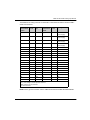
The distribution of analog channels on TELEFAST 2 terminal blocks with the reference ABE7CPA02 are as follows:
50
TELEFAST 2
terminal block
number
AHI0812
pin out
Signal type TELEFAST 2
terminal block
number
AHI0812
pin out
Signal
type
1
NC
Ground
Supp 1
NC
Ground
2
NC
Cable
shield
Supp 2
NC
Ground
EAV16400 04/2014
BME AHI 0812 HART Analog Input Module
TELEFAST 2
terminal block
number
AHI0812
pin out
Signal type TELEFAST 2
terminal block
number
AHI0812
pin out
Signal
type
3
NC
Cable
shield
Supp 3
NC
Ground
4
NC
NC
Supp 4
NC
Ground
100
NC
NC
200
4
COM0
101
3
+IC0
201
NC
Ground
102
NC
NC
202
6
COM1
103
5
+IC1
203
NC
Ground
104
NC
NC
204
8
COM2
105
7
+IC2
205
NC
Ground
106
NC
NC
206
10
COM3
107
9
+IC3
207
NC
Ground
108
NC
NC
208
12
COM4
109
11
+IC4
209
NC
Ground
110
NC
NC
210
14
COM5
111
13
+IC5
211
NC
Ground
112
NC
NC
212
16
COM6
113
15
+IC6
213
NC
Ground
114
NC
NC
214
18
COM7
115
17
+IC7
215
NC
Ground
+ICx: + pole current input for channel x
COMx: - Common pin for channel x
NC: Not Connected
DANGER
HAZARD OF ELECTRIC SHOCK
Confirm that the strap for the ABE7-CPA02 is placed between pin 1 and pin 2. Adjust the strap
position if necessary.
Failure to follow these instructions will result in death or serious injury.
NOTE: For the ground connection, use the additional terminal block ABE7-BV10/20/10E/20E.
EAV16400 04/2014
51
BME AHI 0812 HART Analog Input Module
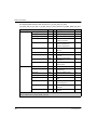
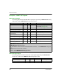
The distribution of analog channels on TELEFAST 2 terminal blocks with the reference ABE7CPA03 are as follows:
TELEFAST 2
terminal block
number
AHI0812
pin out
Signal
type
TELEFAST 2
terminal block
number
AHI0812
pin out
Signal type
1
NC
0 Vdc
Supp 1
NC
24 Vdc
(sensor supply
2
NC
0 Vdc
Supp 2
NC
24 Vdc
(sensor supply
3
NC
0 Vdc
Supp 3
NC
0 Vdc
(sensor supply
4
NC
0 Vdc
Supp 4
NC
0 Vdc
(sensor supply
100
NC
+IS1
200
NC
+IS0
101
NC
NC
201
NC
NC
102
5
+IC1
202
3
+IC0
103
NC
Ground
203
COMX
0 Vdc
104
NC
+IS3
204
NC
+IS2
105
NC
NC
205
NC
NC
106
9
+IC3
206
7
+IC2
107
NC
Ground
207
COMX
0 Vdc
108
NC
+IS5
208
NC
+IS4
109
NC
NC
209
NC
NC
110
13
+IC5
210
11
+IC4
111
NC
Ground
211
COMX
0 Vdc
112
NC
+IS7
212
NC
+IS6
113
NC
NC
213
NC
NC
114
17
+IC7
214
15
+IC6
115
NC
Ground
215
COMX
0 Vdc
+ICx: + pole current input for channel x
+ISx: - pole voltage or current input for channel x
COMx: Common pin for channel x
NC: Not Connected
NOTE: Because the 0 VDC pins of ABE7-CPA03 are internally connected, the COMX pins of
BMEAHI0812 also are connected when joined with ABE7-CAP03.
For the ground connection, use the additional terminal block ABE7-BV10/20/10E/20E.
52
EAV16400 04/2014
BME AHI 0812 HART Analog Input Module
The distribution of analog channels on TELEFAST 2 terminal blocks with the reference ABE7CPA31 are as follows:
TELEFAST 2
AHI0812
terminal block pin out
number
Signal
type
TELEFAST 2
AHI0812
terminal block pin out
number
Signal type
1
NC
Ground
Supp 1
NC
+24 Vdc
(sensor supply)
2
NC
Ground
Supp 2
NC
+24 Vdc
(sensor supply)
3
NC
Ground
Supp 3
NC
0 Vdc
(sensor supply)
4
NC
Ground
Supp 4
NC
0 Vdc
(sensor supply)
100
NC
+IS0
116
NC
+IS4
101
NC
NC
117
NC
NC
102
3
+IC0
118
11
+IC4
103
4
0 V0
119
12
0 V4
104
NC
+IS1
120
NC
+IS5
105
NC
NC
121
NC
NC
106
5
+IC1
122
13
+IC5
107
6
0 V1
123
14
0 V5
108
NC
+IS2
124
NC
+IS6
109
NC
NC
125
NC
NC
110
7
+IC2
126
15
+IC6
111
8
0 V2
127
16
0 V6
112
NC
+IS3
128
NC
+IS7
113
NC
NC
129
NC
NC
114
9
+IC3
130
17
+IC7
115
10
0 V3
131
18
0 V7
+ICx: + pole current input for channel x
+ISx: - pole voltage or current input for channel x
COMx: Common pin for channel x
NC: Not Connected
NOTE: For the ground connection use the additional terminal block ABE7-BV10/20/10E/20E.
EAV16400 04/2014
53
BME AHI 0812 HART Analog Input Module
54
EAV16400 04/2014
Modicon eX80
BME AHO 0412 HART Analog Output Module
EAV16400 04/2014
BME AHO 0412 HART Analog Output Module
Chapter 5
BME AHO 0412 HART Analog Output Module
Overview
This chapter describes the BME AHO 0412 HART analog output module for eX80 platforms, and
shows you how to connect it to actuators.
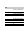
What Is in This Chapter?
This chapter contains the following topics:
Topic
Page
Physical Description
56
BME AHO 0412 Specifications
57
Functional Description
59
Using EMC Kits
62
Wiring Diagrams
64
Using the TELEFAST ABE7-CPA21 Wiring Accessory
67
EAV16400 04/2014
55
BME AHO 0412 HART Analog Output Module
Physical Description
Analog plus HART Communication
The BME AHO 0412 module is a high-density output module that includes 4 isolated analog
channels. Each channel supports HART digital communication.
Use the module with actuators. The module uses a 4-20 mA analog signal to perform continuous
process control functions.
The module also supports the HART protocol, which superimposes a digital signal on top of the
analog signal. The HART digital signal communicates additional instrument information including
instrument status, additional process variables, configuration data, and diagnostics.
Illustration
The BME AHO 0412 analog output module with a 20-pin terminal block accessory:
1
2
LED display
20-pin terminal block accessory
NOTE: The terminal block accessory is supplied separately.
56
EAV16400 04/2014
BME AHO 0412 HART Analog Output Module
BME AHO 0412 Specifications
General Module Specifications
The BME AHO 0412 eX80 HART analog output module possesses the following general
characteristics:
Head module compatibility
Isolation:
between channels
Local rack: BME P58 x0x0 CPU
Remote I/O drop: BME CRA 312 10 adapter
–
1000 Vdc (1 minute duration)
between channels and bus
1400 Vdc (1 minute duration)
between channels and ground
1400 Vdc (1 minute duration)
Operating altitude
0...4000 m
Operating ambient temperature
0...60° C
Vibration
10 mm / 3 g / x10 (per IEC60068-2-6)
Shock
30 g / 11 ms / x3 (per IEC60068-2-27)
Power consumption (3.3 V)
0.38 A
Power consumption (24 V)
0.14 A
Field device support
2-wire / 4-wire
Hot-swap support?
Yes
Analog Specifications
The BME AHO 0412 eX80 HART analog output module possesses the following analog
characteristics:
Number of channels
4
Type of outputs
Current configured by software
Nominal range (full scale)
4-20 mA
Maximum conversion range
0...21 mA
Measurement accuracy for module:
–
Accuracy at 25° C
0.1% of full scale
Accuracy at 0...60° C
0.2% of full scale
Temperature drift
45 ppm / ° C
Display resolution
15-bit plus sign bit
Least significant bit weight
0.366 µA
Refresh time:
–
1. Refresh times are for only the module internal buffer, and are impacted by PLC cycle time.
EAV16400 04/2014
57
BME AHO 0412 HART Analog Output Module
per module
2 ms1
per channel
2 ms1
Response time:
–
with HART enabled
20 ms
with HART disabled
2 ms
600 Ω (0...20 mA)
570 Ω (0...21 mA)
Maximum load impedance
Detection type
broken wire
Monotonicity?
Yes
Non-linearity
0.1% of full scale
1. Refresh times are for only the module internal buffer, and are impacted by PLC cycle time.
HART Specifications
The BME AHO 0412 eX80 HART analog output module possesses the following HART
characteristics:
HART protocols supported2
HART versions 5, 6 and 7
Number of channels
4
Scan time:
–
1s
Typical1
Maximum
1
5s
Detection time for a non-responsive device = (scan time) + (timeouts)
HART command system
ARCOM (interface to a HART master)
Topology
Point-to-point
HART I/O mapping?
Yes
1. Scan time is the same for each channel and for the module. The scan time depends on
the byte length of the command. The scan time values do not include PLC cycle time, which
should be added to determine overall scan time.
2. The eX80 HART output module supports HART up to versions 7.2 and 7.3.
58
EAV16400 04/2014
BME AHO 0412 HART Analog Output Module
Functional Description
Introduction
The BME AHO 0412 eX80 HART analog output module supports 4-20 mA analog communication
and HART digital communication on each of 4 output channels.
Both the eX80 HART analog output module and the 4-20 mA current loop are powered by the
backplane.
NOTE: Because the output module passes 24 Vdc power from the backplane to the current loop,
an external power supply is not required for the current loop.
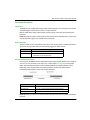
Output Slew Rate
When the HART function is enabled, the slew rate of each analog output is automatically limited.
As a result, the output slew does not unintentionally trigger the HART receiver.
When HART is...
The output slew rate is automatically set to...
Enabled
0,8...0,9 mA/ms
Disabled
>1500 mA/ms (non-inductive load)
>300 mA/ms (1 mH inductive load)
Overshoot/Undershoot Control
Each output on the BME AHO 0412 eX80 HART analog output module operates over a range of
4-20 mA. You can use Unity Pro to map up to 3 current ranges (see page 99) for each output.
Upper and lower tolerance detections are enabled regardless of overflow/underflow control.
Depending on the range specified, the module checks for overflow and verifies that the
measurement falls between a lower and an upper threshold:
Designation
Description
Nominal range
The specified measurement range
Overshoot area
The range of values located above the upper threshold
Undershoot area
The range of values located below the lower threshold
NOTE: Monitoring of values in the overshoot and undershoot areas can be enabled or disabled in
Unity Pro.
EAV16400 04/2014
59
BME AHO 0412 HART Analog Output Module
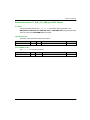
The values of the thresholds are configurable independently from one another. Both the default
values, and the maximum and minimum configurable values are as follows:
Range
BME AHO 0412 Range
Undershoot Area
Nominal Range
Overshoot Area
Default setting
–2,500
–801
–8000
10,300
10,301
10,625
Minimum /
Maximum
–32,768
...
...
...
...
32,767
Writing Outputs
The application can provide the outputs with values using the standard display (in %, to 2 decimal
places):
Type of Range
Display
4-20 mA
from 0 to 10,000 (0% to 100%)
It is also possible to define the range of values within which measurements are expressed, by
selecting:
the minimum nominal value corresponding to the minimum value for the range: 0 %.
the maximum nominal value corresponding to the maximum value for the range (100 %).
The lower and upper thresholds can be integers between –32,768 and +32,767.
Output Behavior on Program Interruption
In the event the BME AHO 0412 HART analog module detects an event that stops program
execution, depending upon the seriousness of the interruption, each of the outputs undertakes one
of the following responses:
apply its fallback/maintain position
be forced to 0 mA
Output behaviors:
60
If the detected event is...
The output response is...
Task in STOP mode, or program missing
Fallback/Maintain (channel by channel)
Communication interruption
Fallback/Maintain (channel by channel)
Configuration detected error
0 mA (all channels)
Internal detected error in module
0 mA (all channels)
Output value out of range
(undershoot/overshoot)
Value saturated at the defined limit
(channel by channel)
Open circuit
Maintain (channel by channel)
Module hot swapping (processor in STOP
mode)
0 mA (all channels)
EAV16400 04/2014
BME AHO 0412 HART Analog Output Module
If the detected event is...
The output response is...
Reloading program
0 mA (all channels)
Behavior during initial power-up and power
off
0 mA (all channels)
Actuator Alignment
The process of alignment involves the elimination of an observed systematic offset, around a
specific operating point, for a given actuator. Actuator alignment compensates for a detected
variation that is linked to the process. Replacing a module does not require a new alignment.
However, replacing the actuator or changing the actuator operating point requires a new
alignment.
Conversion lines are as follows:
The alignment value is editable from a programming console, even if the program is in RUN mode.
For each output channel, you can:
view and modify the desired measurement value
save the alignment value
determine whether the channel already has an alignment
The alignment offset may also be modified through programming.
Channel alignment is performed on the channel in standard operating mode, without any effect on
the channel operating modes.
The maximum offset between measured value and desired (aligned) value may not exceed +/1,500.
NOTE: To align multiple analog channels on the BME AHO 0412 eX80 HART analog output
module, proceed channel by channel, aligning one channel at a time. Test each channel after
aligning it before proceeding to align the next channel.
EAV16400 04/2014
61
BME AHO 0412 HART Analog Output Module
Using EMC Kits
Introduction
To help shield the BME AHO 0412 signals from outside interference induced in series mode and
interference in common mode, use EMC kits to ground the shielded cables connected to the
module.
Cable Shielding
Connect the cable shielding to the grounding bar. Clamp the shielding to the shield bar on the
module side. Use the BMX XSP 0400/0800/1200 EMC kit to connect the shielding.
DANGER
HAZARD OF ELECTRIC SHOCK, EXPLOSION, OR ARC FLASH
While mounting / removing the modules:
confirm that each terminal block is connected to the shield bar and
disconnect voltage supplying sensors and pre-actuators.
Failure to follow these instructions will result in death or serious injury.
1
3
2
4
1
2
3
4
BME AHO 0412
Shield bar
Clamp
To pre-actuators
Using Pre-Actuators Referenced in Relation to the Ground
There are no specific technical constraints for referencing pre-actuators to the ground. It is
nevertheless preferable to avoid returning a remote ground potential to the terminal that may be
different to the ground potential close by.
62
EAV16400 04/2014
BME AHO 0412 HART Analog Output Module
DANGER
HAZARD OF ELECTRIC SHOCK
Sensors and other peripherals may be connected to a grounding point some distance from the
module. Such remote ground references may carry considerable potential differences with
respect to local ground. Confirm that:
potentials greater than safety limits cannot exist,
induced currents do not affect the measurement or integrity of the system.
Failure to follow these instructions will result in death or serious injury.
Electromagnetic Hazard Instructions
CAUTION
UNEXPECTED BEHAVIOR OF APPLICATION
To reduce electromagnetic perturbations, use the BMX XSP 0400/0800/1200 EMC kit to connect
the shielding without programmable filtering.
Electromagnetic perturbations may lead to an unexpected behavior of the application.
Failure to follow these instructions can result in injury or equipment damage.
EAV16400 04/2014
63
BME AHO 0412 HART Analog Output Module
Wiring Diagrams
Point-to-Point Connections
The BME AHO 0412 eX80 HART analog output module supports point-to-point 4-20 mA wiring
connections to field instruments, including actuators and transmitters. You can make the
connection to the output module using a BMX FTB 20x0 20-pin terminal block, or a TELEFAST
cable (which includes a 20-pin terminal block).
The output module provides 4-20 mA current loop power.
Output Module Pinout
The BME AHO 0412 eX80 HART analog output module present the following 20-pin design, to
which you can connect a terminal block or TELEFAST cable:
64
EAV16400 04/2014
BME AHO 0412 HART Analog Output Module
BME AHO 0412 with 2-Wire or 4-Wire Transmitter
This example illustrates how to connect the output module to a either a 2-wire or a 4-wire
transmitter. Field power is provided to the transmitter only in the 4-wire design:
1
2
3
4
5
2-wire or 4-wire transmitter
4-20 mA current loop, with arrows indicating direction of current flow
Field power supply (for 4-wire design only)
Protective ground
Secondary HART master (hand-held)
BME AHO 0412 with 2-Wire or 4-Wire Transmitter, TELEFAST Connector
This example illustrates how to connect the output module to either a 2-wire or a 4-wire transmitter
using a TELEFAST wiring accessory and cable. The cable includes a 20-pin terminal block. Field
power is supplied to the transmitter only for the 4-wire design.
1
2
3
4
5
2-wire or 4-wire transmitter
4-20 mA current loop, with arrows indicating direction of current flow
Field power supply (for 4-wire design only)
Protective ground
Secondary HART master (hand-held)
EAV16400 04/2014
65
BME AHO 0412 HART Analog Output Module
HART Network Cable Characteristics and Lengths
The HART Communication Foundation has developed documentation describing recommended
types and diameters of cable for HART networks. This documentation also includes instructions on
how to calculate maximum cable lengths for a HART network.
To obtain a copy of this documentation, visit the HART Communication Foundation website at
www.hartcomm.org, and download the document FSK Physical Layer Specification (document
number HFD_SPEC-054). HART network cable characteristics and lengths information can be
found at section 7.5 of this document.
66
EAV16400 04/2014
BME AHO 0412 HART Analog Output Module
Using the TELEFAST ABE7-CPA21 Wiring Accessory
Introduction
The BME AHO 0412 module can be connected to a TELEFAST ABE7-CPA21 wiring accessory.
The module is connected to the wiring accessory using one of the following cables:
BMX FCA 150: length 1.5 m (4.92 ft)
BMX FCA 300: length 3 m (9.84 ft)
BMX FCA 500: length 5 m (16.40 ft)
Connecting Modules
Modules can be connected to a TELEFAST ABE7-CPA21 as shown in the diagram below:
1
2
3
4
5
BME AHO 0412
TELEFAST ABE7-CPA21
Clamp
Shield bar
BMX FCA 150/300/500
EAV16400 04/2014
67
BME AHO 0412 HART Analog Output Module
Connecting Sensors
Actuators may be connected to the ABE7-CPA21 wiring accessory as depicted in the Wiring
Diagrams (see page 64) topic.
The distribution of analog channels on TELEFAST 2 terminal blocks with the reference ABE7CPA21 are as follows:
TELEFAST 2
terminal block
number
AHO0412
pinout
Signal type TELEFAST 2
terminal block
number
AHO0412
pinout
Signal
type
1
NC
Ground
Supp 1
NC
Ground
2
NC
Cable
shield
Supp 2
NC
Ground
3
NC
Cable
shield
Supp 3
NC
Ground
4
NC
Cable
shield
Supp 4
NC
Ground
100
1
CH0
200
2
COM0
101
NC
NC
201
NC
Ground
102
7
CH1
202
8
COM1
103
NC
NC
203
NC
Ground
104
11
CH2
204
12
COM2
105
NC
NC
205
NC
Ground
106
17
CH3
206
18
COM3
107
NC
NC
207
NC
Ground
COMx: Common pin for channel x
NC: Not connected
DANGER
HAZARD OF ELECTRIC SHOCK
Confirm that the strap for the ABE7-CPA21 is placed between pin 1 and pin 2. Adjust the strap
position if necessary.
Failure to follow these instructions will result in death or serious injury.
NOTE: For the ground connection, use the additional terminal block ABE7-BV10/20/10E/20E.
68
EAV16400 04/2014
Modicon eX80
Ethernet Services
EAV16400 04/2014
Ethernet Services
Chapter 6
Ethernet Services
Overview
This chapter presents the Ethernet services supported by the BME AHI 0812 and BME AHO 0412
HART analog I/O modules.
What Is in This Chapter?
This chapter contains the following topics:
Topic
Page
Fast Device Replacement
70
Upgrading Firmware
71
EAV16400 04/2014
69
Ethernet Services
Fast Device Replacement
Overview
The fast device replacement (FDR) service employs a central FDR server to store the following
parameters for a BME AHI 0812 or BME AHO 0412 analog I/O module:
IP addressing parameters, and
Module configuration parameters.
When you replace a module, the server automatically configures the replacement module with the
identical parameters as the replaced module. The FDR service removes the need for service
personnel to maintain configuration records and reduces the possibility of human error in entering
the new configuration.
FDR Server
The M580 Ethernet CPU includes an FDR server. The server is a passive device that stores both
IP addressing and configuration parameters for the modules on the network. Each network module
is identified by its device name. After the FDR service is enabled, the server responds to requests
from the FDR clients.
FDR Client
The BME AHI 0812 and BME AHO 0412 analog I/O modules are FDR clients. They use the FDR
server to facilitate replacement of the module. Each client is assigned a device name that uniquely
identifies it from other modules on the network. After the module is connected to the network, it
receives a copy of its operating parameters from the FDR server. These parameter settings enable
a replacement module to operate exactly as the original client.
You can use the gateway DTM to send an updated parameter file to the FDR server, where it is
stored in Flash memory.
How FDR Works
When it is time to replace a module, the following occurs:
Sequence
70
Event
1
Your service personnel needs to assign the device name of the original
module to the replacement module.
2
Your service personnel places the new module on the network, which is
configured to use the DHCP client service.
3
The module automatically sends a request to the server for a set of IP
parameters that is used by a module with this device name.
4
The module receives the IP parameters and then connects to the FDR server
and downloads a copy of its operating parameters.
5
After the parameters are downloaded, the module implements the
parameters and resumes operation.
EAV16400 04/2014
Ethernet Services
Upgrading Firmware
Using Unity Loader
Use Unity Loader to install firmware upgrades for the HART analog I/O modules. Unity Loader is
a stand-alone utility that ships with your Unity Pro software.
NOTE: Before you can upgrade firmware, you first need to:
Enable Firmware upgrade in the Security page for the gateway DTM; then
With the gateway DTM selected in the DTM Browser, click the right mouse button and select
the Device menu → Additional functions → Transfer to FDR Server command to update
the edited configuration in the FDR server.
Installing Unity Loader
Insert the Unity Loader installation CD in the CD-ROM drive of your maintenance PC. Autorun
launches the setup automatically. If not, double-click Setup.exe. The Unity Loader Installation
Wizard will guide you through the Unity Loader installation.
Physically Connecting to the Module
After an IP address has been assigned to the module, the next step is to connect your maintenance
PC to the module. You can either directly connect your PC to the module, or merely connect your
PC to the Ethernet network to which your module is connected.
EAV16400 04/2014
71
Ethernet Services
Connecting Unity Loader to the module
To establish a connection between Unity Loader and the module, follow these steps:
Step
Action
1
Open Unity Loader on your PC: Start → Programs → Schneider Electric → Unity Loader. Unity
Loader opens and displays the Project tab:
2
In the Connection part of the page, make the following settings:
Media
Address
Select Ethernet
Type in the module IP address.
NOTE: Confirm that you are using the IP address for the HART I/O module, and not
the CPU.
3
Click Connect.
Performing the Upgrade
Before beginning a firmware upgrade, confirm that the module is in Stop mode.
The firmware upgrade for a module is contained in a file with an .LDX extension. The single .LDX
file contains the necessary module firmware upgrades.
72
EAV16400 04/2014
Ethernet Services
Before upgrading the firmware, Unity Loader confirms that the firmware upgrade file is compatible
with your module.
Do not interrupt the firmware download process:
Do not allow an interruption to the power or the communications during the firmware upgrade
process.
Do not shut down the Unity Loader software during the upgrade.
If the firmware download process is interrupted, the new firmware is not installed and the adapter
continues to use the old firmware. If an interruption occurs, cycle power to the HART module and
restart the process.
Open Unity Loader on your PC and update the firmware for the remote I/O adapter:
Step
Action
1
After Unity Loader has connected to the module, click the Firmware tab.
2
In the PLC area of the Firmware tab, confirm that the Module check-box is de-selected.
3
In the PC area, click the ellipsis (...) button to open a dialog where you can navigate to and select the
firmware file for your module. The firmware is contained in a Unity Loader file (.ldx extension).
After you select the firmware file and close the dialog, the selected revision of this firmware is displayed
in the list on the left, and the current version of the firmware is displayed in the list on the right.
EAV16400 04/2014
73
Ethernet Services
Step
4
Action
When the arrow in the middle of the screen (above) is green, click Transfer.
NOTE: Only click Transfer if the arrow is green. A yellow arrow indicates that the firmware file on your
computer is the same version or newer than the file selected for transfer; a red arrow indicates that the
firmware on the computer is not compatible with the module.
5
Click yes on the 2 dialogs that appear. A third dialog appears (below), which indicates the transfer status
with the blue bars at the bottom of the screen. After the message “Firmware upgraded successfully” is
displayed (below), click Close.
6
In the Unity Loader software, click Disconnect and close the window.
The module reboots itself on completion of the firmware upgrade.
Unity Loader includes its own user documentation. Refer to the Unity Loader a SoCollaborative
Software User Manual for assistance when you perform the firmware upgrade.
74
EAV16400 04/2014
Modicon eX80
Introducing HART
EAV16400 04/2014
Introducing HART
Chapter 7
Introducing HART
Overview
This chapter introduces the Highway Addressable Remote Transducer (HART) protocol, and
describes the embedded HART multiplexer functionality in both the BME AHI 0812 analog input
module and the BME AHO 0412 analog output module.
What Is in This Chapter?
This chapter contains the following sections:
Section
EAV16400 04/2014
Topic
Page
7.1
Introducing the HART Multiplexer
76
7.2
Explicit Messaging Using the DATA_EXCH Block
83
75
Introducing HART
Introducing the HART Multiplexer
Section 7.1
Introducing the HART Multiplexer
Overview
This section introduces the HART protocol, and describes HART multiplexer communication and
commands.
What Is in This Section?
This section contains the following topics:
Topic
76
Page
Introducing HART
77
HART Multiplexer Communication
79
HART Multiplexer Commands
81
EAV16400 04/2014
Introducing HART
Introducing HART
HART
The Highway Addressable Remote Transducer (HART) protocol provides digital communication to
microprocessor-based analog process control instruments.
HART uses the Bell 202 frequency-shift-keying (FSK) standard to superimpose a digital signal on
top of the 4-20mA current loop analog signal:
the analog signal communicates the primary measured process variable value
the digital signal communicates additional instrument information including instrument status,
additional process variables, configuration data, and diagnostics
The digital signal shifts between a frequency of 1200 Hz (representing a binary 1) and a frequency
of 2200 Hz (representing a binary 0):
These digital signal frequencies are higher than the typical analog signaling frequency range of
0...10 Hz. The digital signal is typically isolated using a passive high-pass filter with a cut-off
frequency in the range of 400...800 Hz. The analog signal is likewise isolated using a passive lowpass filter.
The separation in frequency between HART and analog signaling allows both signals to coexist on
the same current loop. Because the HART digital signal is phase continuous, the HART digital
signal:
does not interfere with the 4-20 mA signal, and
allows the analog process to continue operating during HART digital communication
EAV16400 04/2014
77
Introducing HART
Half-duplex Communication Protocol
HART communication is half-duplex in design, which means that a HART-compliant instrument
does not simultaneously transmit and receive.
Master - Slave Protocol
HART is a master-slave protocol. A HART-slave responds only when commanded by a HART
master. Examples of HART-compliant instruments include:
HART masters:
asset management software (AMS) running on a PC
a HART interface module, for example, the HART modem feature of both the BME AHI 0812
input module and the BME AHO 0412 output module when communicating with a HART
process control instrument (such as a HART-compliant sensor or actuator)
a hand-held device temporarily attached to the network
HART slaves:
a HART process control instrument
a HART interface module, for example, the HART modem feature of both the BME AHI 0812
input module and the BME AHO 0412 output module when operating as a slave with asset
management software (AMS) or a HART server
78
EAV16400 04/2014
Introducing HART
HART Multiplexer Communication
Embedded HART Multiplexer
Both the BME AHI 0812 input module and the BME AHO 0412 output module include an
embedded HART multiplexer. The multiplexer facilitates the transmission of HART field instrument
data by providing:
one-to-many HART communication between a single HART master and multiple HART field
devices, and
HART instrument data to a PLC master, as part of the periodic scan
HART Primary and Secondary Masters
A HART master can be either:
a primary master, such as a:
configuration PC running Unity Pro, or asset management software
PC running SCADA as HART server
a secondary master, such as a hand-held device that can be temporarily connected directly to
the current loop between an I/O module and the HART field instrument
EAV16400 04/2014
79
Introducing HART
1
2
3
4
5
6
Local rack containing a BME P58 3040 CPU with remote I/O scanning service
Remote I/O rack containing a BME CRA 312 10 adapter module
Remote I/O main ring
HART-enabled field instruments connected to I/O via 4-20 mA current loop wiring
Maintenance PC operating as HART primary master (running, for example, Unity Pro configuration
software or asset management software) or SCADA
Hand-held HART secondary master
The HART multiplexer supports one HART field instrument per I/O channel.
80
EAV16400 04/2014
Introducing HART
HART Multiplexer Commands
Overview
The HART multiplexer within the HART analog I/O modules support the following HART
multiplexer commands.
Universal Commands
Command
Description
1
Read primary variable
2
Read loop current and percentage of range
3
Read dynamic variables and loop current
6
Write polling address
7
Read loop configuration
8
Read dynamic variable classifications
9
Read device variables with status
11
Read unique identifier associated with tag
12
Read message
13
Read tag, descriptor, and date
14
Read primary variable transducer information
15
Read device information
16
Read final assembly number
17
Write message
18
Write tag, descriptor, and date
19
Write final assembly number
20
Read long tag
21
Read unique identifier associated with long tag
22
Write long tag
38
Reset configuration changed flag
48
Read additional device status
Common Practice Commands
Command
Description
42
Perform device reset
59
Write number of response preambles
106
Flush delayed response
EAV16400 04/2014
81
Introducing HART
ARCOM Multiplexer Common Practice Commands
Command
82
Description
128
Read parameters
129
Read loop status
130
Read instrument list from index
131
Read instrument static data
132
Write instrument static data
133
Remove instrument from instrument list
134
Read scan list from index
135
Read instrument dynamic data
136
Read instrument scan status
137
Write instrument scan status
138
Read instrument cumulative responses
139
Reset instrument cumulative responses
140
Read instrument tries and failures
141
Reset instrument tries and failures
142
Read counts of host communications
143
Reset counts of host communications
144
Read retry limits
145
Write retry limits
146
Read scan command
147
Write scan command
148
Read scan status
149
Write scan status
150
Read gender
151
Write gender
152
Read loop search type
153
Write loop search type
154
Rebuild loops
155
Copy command and reply (pass-through)
EAV16400 04/2014
Introducing HART
Explicit Messaging Using the DATA_EXCH Block
Section 7.2
Explicit Messaging Using the DATA_EXCH Block
Overview
This section introduces you to the DATA_EXCH function block, which you can use to configure
explicit messages containing HART requests.
What Is in This Section?
This section contains the following topics:
Topic
Page
Configuring Explicit Messaging Using DATA_EXCH
84
Configuring EtherNet/IP Explicit Messaging Using DATA_EXCH
86
Configuring the DATA_EXCH Management Parameter
87
Configuring EtherNet/IP Explicit Messaging Using DATA_EXCH
88
Viewing the DATA_EXCH Received_Data Parameter
89
EAV16400 04/2014
83
Introducing HART
Configuring Explicit Messaging Using DATA_EXCH
Overview
Use the DATA_EXCH function block to configure EtherNet/IP connected and unconnected explicit
messages.
The Management_Param, the Data_to_Send, and the Received_Data parameters define the
operation.
EN and ENO can be configured as additional parameters.
FBD Representation
Input Parameters
Parameter
Data type
Description
Address
Array [0...7] of INT
The path to the destination device, the content of which can
vary depending on the message protocol. Use the ADDM
function.
ActionType
INT
The type of action to perform. This setting = 1 (transmission
followed by await reception).
Data_to_Send
Array [n...m] of INT
The EtherNet/IP and CIP request codes that define the type
of message to send, plus any data that needs to be included
with the request.
Refer to the to the topic Configuring the Data_To_Send
Parameter (see page 88).
Input/Output Parameters
84
Parameter
Data type
Description
Management_Param
Array [0...3] of INT
The management parameter (see page 87), consisting
of 4 words.
EAV16400 04/2014
Introducing HART
Output Parameters
Parameter
Data type
Description
Received_Data
Array [n...m] of INT
The EtherNet/IP response (see page 89).
EAV16400 04/2014
85
Introducing HART
Configuring EtherNet/IP Explicit Messaging Using DATA_EXCH
Configuring the Address Parameter
To configure the Address parameter, use the ADDMX function to convert the character string,
described below, to an address:
ADDMX(‘rack.slot.channel{ip_address}message_type.protocol’), where:
86
Field
Description
Setting
rack
The number assigned to the rack containing the communication Application
module.
specific
slot
The position of the communication module in the rack.
Application
specific
channel
The communication channel.
3
ip_address
The IP address of the BME AHI 0812 or BME AHO 0412.
Application
specific
message_type
The type of message, presented as a three character string:
UNC (indicating an unconnected message), or
CON (indicating a connected message)
UNC
protocol
The protocol type.
CIP
EAV16400 04/2014
Introducing HART
Configuring the DATA_EXCH Management Parameter
Configuring the Management Parameter
The Management parameter consists of 4 contiguous words, described below:
Data source
Register
Data managed by Management_Param[0]
the system
Management_Param[1]
Data managed by Management_Param[2]
the user
Management_Param[3]
Description
High Byte (MSB)
Low Byte (LSB)
Exchange number
Two read-only bits:
Bit 0 = Activity bit (see below)
Bit 1 = Cancel bit
Operation report
(see page 217)
Communication report (see page 216)
Block timeout. Values include:
0 = infinite wait
other values = timeout x 100 ms, for example:
1 = 100 ms
2 = 200 ms
Length of data sent or received:
Input (before sending the request): length of data in the
Data_to_Send parameter, in bytes
Output (after response): length of data in the Received_Data
parameter, in bytes
Activity Bit:
This bit indicates the execution status of the communication function.
It is set to 1 when launched, and returns to 0 when its execution is complete.
It is the first bit of the first element of the table.
Example: if the management table has been declared as follows:
Management_Param[0] ARRAY [0..3] OF INT,
the activity bit is the bit with the notation Management_Param[0].0.
NOTE: The notation previously used requires configuration of the project properties in such a way
as to authorize the extraction of bits on integer types. If this is not the case,
Management_Param[0].0 cannot be accessed in this manner.
EAV16400 04/2014
87
Introducing HART
Configuring EtherNet/IP Explicit Messaging Using DATA_EXCH
Configuring the Data_to_Send Parameter
The Data_to_Send parameter varies in size. It consists of contiguous registers that include—in
sequence—both the message type and the CIP request:
Variable
Byte Offset
Data Type
Description
Value
DataToSend[0]
0
Bytes
Message type:
High byte = size of the request in words:
16#03 hex (3 decimal)
Low byte = EtherNet/IP service code:
16#4B (75 decimal)
16#034B
DataToSend[1]
2
Bytes
CIP request class information - Class
Segment:
High byte = 16#00 hex (0 decimal)
Low byte = 16#21 (33 decimal)
16#0021
DataToSend[2]
4
Bytes
CIP request class information - class:
High byte = 16#04 hex (4 decimal)
Low byte = 16#10 (16 decimal)
16#0410
DataToSend[3]
6
Bytes
CIP request instance information:
High byte = instance: 16#01 (1 decimal)
Low byte = instance segment: 16#24
(36 decimal)
16#0124
DataToSend[4...n] 8
Bytes
HART request (see below)
–
The HART request consists of the following fields:
Byte Offset
Field
Data Type
Description
8
Delimiter
Byte
Indicates the position of the byte count and frame type.
9 or 9...13
Address
Byte or bytes
Short address or long address.
10 or 14
Command
Bytes
CIP request class information - class:
High byte = 16#04 hex (4 decimal)
Low byte = 16#10 (16 decimal)
11 or 15
Byte Count
Byte
Represents the number of data bytes in this request.
Byte array1
(Optional) Application layer data.
12...n or 16...n Data
1. Each array entry presents 2 bytes of data in little endian format, where the least significant byte is stored
in the smallest memory address.
Refer to Token-Passing Data Link Layer Specification, Universal Command Specification and
Arcom Multiplexer Specification.
88
EAV16400 04/2014
Introducing HART
Viewing the DATA_EXCH Received_Data Parameter
Contents of the Received_Data Parameter
The Received_Data parameter contains only the EtherNet/IP response. The length of the
response varies, and is reported by Management_Param[3] after the response is received. The
format of the response is described, below:
Byte Offset
Field
Data Type
Description
0
Reply Service
Byte
Service of the explicit message + 16#80
1
<Reserved>
Byte
–
2
General Status
Byte
Ethernet/IP general status
3
Size of Additional Status
Byte
Additional Status array size, in words
4
Additional Status
Word array
Additional status
5
Data1
Word array
Response data from request, or additional
detected error data if General Status indicates a
detected error.
Response
1. The response is structured in little endian order.
NOTE: Refer to The CIP Networks Library, Volume 1, Common Industrial Protocol at section 3-5.6
Connection Manager Object Instance Error Codes.
EAV16400 04/2014
89
Introducing HART
90
EAV16400 04/2014
Modicon eX80
Configuring HART Analog I/O
EAV16400 04/2014
Configuring BME AHI 0812 and BME AHO 0412 Modules in Unity Pro
Chapter 8
Configuring BME AHI 0812 and BME AHO 0412 Modules in
Unity Pro
Overview
This chapter describes how to add a HART analog I/O module to the PLC Bus, and then configure
the module using dialogs you can access from the PLC Bus.
What Is in This Chapter?
This chapter contains the following sections:
Section
EAV16400 04/2014
Topic
Page
8.1
Adding and Configuring HART Analog I/O
92
8.2
Configuring X80 Analog Device DDT Parameters
101
91
Configuring HART Analog I/O
Adding and Configuring HART Analog I/O
Section 8.1
Adding and Configuring HART Analog I/O
Overview
This section describes how to add a HART analog I/O module to the PLC Bus, and then configure
the module using Unity Pro screens that you can access from the PLC Bus.
What Is in This Section?
This section contains the following topics:
Topic
92
Page
Creating a New M580 Project in Unity Pro
93
Adding HART Analog I/O Modules to the Project
94
Configuring Analog Input Channels for the BME AHI 0812
97
Configuring Analog Output Channels for the BME AHO 0412
99
EAV16400 04/2014
Configuring HART Analog I/O
Creating a New M580 Project in Unity Pro
Creating the New Project
When you open Unity Pro, follow these steps to create a new project:
Step
Action
1
Select File → New. The New Project dialog opens.
2
In the PLC area, expand the Modicon M580 node and select a BME P58 x040 CPU.
3
In the Rack area, expand Modicon M580 local drop → Rack and select a BME XBP xx00
backplane.
4
Click OK to save your selections.
5
In the Project Browser, navigate to then double-click Project → Configuration → 0 : PLC
Bus. The PLC Bus window opens, displaying the selected rack, CPU, and default power supply
module.
You can now add modules to the local main rack.
Adding a Remote Rack to the Project
If your project will include both a local and a remote rack, follow these steps to create the remote
rack:
Step
Action
1
In the Project Browser, navigate to then double-click Project → Configuration → 2: EIO Bus.
The EIO Bus window opens, displaying an empty rectangle.
2
Double-click on the rectangle. The New Device window opens, displaying 2 lists.
3
In the Drop end communication list, select one of the BMX CRA adapter modules.
4
Click OK to save your selections.
5
The EIO Bus window now displays the selected rack, with the selected BMX CRA adapter
module placed in slot 0.
5
Place your cursor over an empty slot to the left of the BMX CRA adapter module, click the right
mouse button, then select New Device.... The New Device window opens.
6
In the New Device window, select a power supply for the remote rack, then click OK. The
EIO Bus window now displays the selected BMX CRA adapter and power supply.
You can now add modules to the remote main rack.
EAV16400 04/2014
93
Configuring HART Analog I/O
Adding HART Analog I/O Modules to the Project
Before You Begin
You can add a BME AHI 0812 input module or a BME AHO 0412 output module only to a main
rack that includes a BME XBP xx00 Ethernet backplane. If that rack is:
a local main rack, it needs to include a BME P58 x040 Ethernet CPU
a remote main rack, it needs to include a BME CRA 312 10 adapter
Adding a New HART Analog I/O Module
To add a new HART analog I/O module to the project, follow these steps:
Step
1
Action
In the Project Browser, right click the PLC Bus node, and then select Open from the context
menu. The PLC Bus opens.
In the Project Browser:
to add a module to the local rack, right click the PLC Bus node, and then select Open from the
context menu.
to add a module to a remote rack, right click the EIO Bus node, and then select Open from the
context menu.
The selected bus opens.
2
In the PLC Bus, right-click in a slot where you want to insert a HART analog I/O module. A context
menu opens:
NOTE: In this example, modules are added to the PLC Bus.
94
EAV16400 04/2014
Configuring HART Analog I/O
Step
Action
3
Select New Device.... The New Device dialog opens:
4
In the New Device dialog, make the following selections:
Select a HART analog I/O module (in this example, a BME AHI 0812 input module); then
For this local rack, select the I/O data type for your module, either:
Topological: supports only analog data
Device DDT (default): supports both analog and HART data
NOTE: For a remote rack, Device DDT is pre-selected.
EAV16400 04/2014
95
Configuring HART Analog I/O
Step
5
Action
Click OK. The selected module is added to the PLC Bus and to the Project Browser (below):
NOTE: If you add a module to the remote rack, it appears beneath EIO Bus.
6
In the PLC Bus window, double-click on the Ethernet ports of the CPU. The
RIO DIO Communicator Head window opens.
7
In the Security tab, make the following selections:
FTP: select Enabled, to permit configuration transfers between the CPU and modules on the
main rack.
TFTP: select Enabled, to permit configuration transfers between the CPU and modules on a
remote rack.
8
In the Edit toolbar, click the Validate (
) button.
To configure the HART analog I/O module, right-click on the module in the Project Browser, and
then select Open.
NOTE: In addition to configuring the HART analog I/O module, you also need to add and configure
the HART analog I/O module DTM (see page 105).
96
EAV16400 04/2014
Configuring HART Analog I/O
Configuring Analog Input Channels for the BME AHI 0812
Analog Input Channels
The BME AHI 0812 HART analog input module includes 8 input channels. To open the module for
configuration in Unity Pro, double-click the input module in the PLC Bus:
Channel Parameters
To configure an input channel, select that channel on the left side of the configuration dialog. You
can edit the following parameters for each of the 8 channels:
Parameter
Description
Used
The status of the channel:
Selected = enabled (default)
De-selected = disabled
Symbol
(Read only) Displays the variable that has been associated with this
channel.
Range
(Read only) Displays the current loop range of 4...20 mA.
EAV16400 04/2014
97
Configuring HART Analog I/O
Parameter
Description
Scale
Click in this field to open the following dialog where you can input the
following scaling and overflow (see page 37) parameters:
Filter
98
Scaling: 0%:
Input the percentage scaling value for 4 mA current
(default = 0).
Scaling: 100%:
Input the percentage scaling value for 20 mA current
(default = 10,000).
Overflow: Below
The threshold between the lower tolerance area and
the underflow area (default = –800).
Overflow: Below
(checkbox)
The status of underflow control:
Selected = enabled (default)
De-selected = disabled
Overflow: Above
The threshold between the upper tolerance area and
the overflow area (default = 10,800).
Overflow: Above
(checkbox)
The status of overflow control:
Selected = enabled (default)
De-selected = disabled
The Required Value used to perform first order filtering of the analog signal
(see page 39). Values include:
0: no filtering
1, 2: low filtering
3, 4: medium filtering
5, 6: high filtering
EAV16400 04/2014
Configuring HART Analog I/O
Configuring Analog Output Channels for the BME AHO 0412
Analog Output Channels
The BME AHO 0412 HART analog output module includes 4 output channels. To open the module
for configuration in Unity Pro, double-click the output module in the PLC Bus:
Channel Parameters
To configure an output channel, select that channel on the left side of the configuration dialog. You
can edit the following parameters for each of the 4 channels:
Parameter
Description
Symbol
(Read only) Displays the variable that has been associated with this channel.
Range
(Read only) Displays the current loop range of 4...20 mA.
EAV16400 04/2014
99
Configuring HART Analog I/O
Parameter
Description
Scale
Click in this field to open the following dialog where you can input scaling and overflow
(see page 37) parameters:
Fallback
Scaling: 0%:
Input the percentage scaling value for 4 mA current (default = 0).
Scaling: 100%:
Input the percentage scaling value for 20 mA current (default =
10,000).
Overflow: Below
The threshold between the lower tolerance area and the underflow
area (default = –800).
Overflow: Below
(checkbox)
The status of underflow control:
Selected = enabled (default)
De-selected = disabled
Overflow: Above
The threshold between the upper tolerance area and the overflow
area (default = 10,300).
Overflow: Above
(checkbox)
The status of overflow control:
Selected = enabled (default)
De-selected = disabled
Use this checkbox to specify the behavior of the output when the PLC is in STOP mode or
if communication between the PLC and the output module has stopped:
Selected: the value specified in the Fallback Value parameter is assigned to the output.
De-selected: the output maintains its value.
Fallback value If the Fallback parameter is selected, this value is assigned to the output on fallback. The
range of available values is defined by the 0%...100% scaling settings.
Wiring Ctrl
100
The wiring control function checks for a broken wire. Use the checkbox to activate and deactivate wiring control, as follows:
Selected = wiring control is enabled
De-selected = wiring control is disabled (default)
EAV16400 04/2014
Configuring HART Analog I/O
Configuring X80 Analog Device DDT Parameters
Section 8.2
Configuring X80 Analog Device DDT Parameters
Overview
This section describes how to configure an X80 analog I/O module DDT parameters, where the
module is placed in a remote I/O drop.
What Is in This Section?
This section contains the following topics:
Topic
Page
Device DDT Parameters for the BME AHI 0812
102
Device DDT Parameters for the BME AHO 0412
103
EAV16400 04/2014
101
Configuring HART Analog I/O
Device DDT Parameters for the BME AHI 0812
Device DDT Parameters (Remote I/O Drop)
This topic describes the Unity Pro Device DDT tab for a BME AHI 0812 HART analog input
module, which is placed in an Ethernet remote I/O drop that includes a BME CRA 312 10 adapter
module. A derived data type (DDT) is a set of elements with the same type (ARRAY) or with different
types (structure).
NOTE: These instructions assume that you have already added a drop to your Unity Pro project.
Access the Device DDT Tab
Access the Device DDT parameters in Unity Pro:
Step
Action
1
In the PLC Bus, double-click the BME AHI 0812 HART analog input module.
The module configuration window opens.
2
Select the Device DDT tab.
The Device DDT tab contains a name and a type:
Parameters
Use the Unity Pro Device DDT tab to configure these parameters for the analog I/O module on the
remote I/O rack:
102
Parameter
Description
Name
The default device DDT instance name is MOD_ANA_8_x (where x
equals the module number).
Type
The module type (read-only).
Goto details
Links to the DDT data editor.
EAV16400 04/2014
Configuring HART Analog I/O
Device DDT Parameters for the BME AHO 0412
Device DDT Parameters (Remote I/O Drop)
This topic describes the Unity Pro Device DDT tab for a BME AHO 0412 HART analog output
module, which is placed in an Ethernet remote I/O drop that includes a BME CRA 312 10 adapter
module. A derived data type (DDT) is a set of elements with the same type (ARRAY) or with different
types (structure).
NOTE: These instructions assume that you have already added a drop to your Unity Pro project.
Access the Device DDT Tab
Access the Device DDT parameters in Unity Pro:
Step
Action
1
In the PLC Bus, double-click the BME AHO 0412 HART analog input module.
The module configuration window opens.
2
Select the Device DDT tab.
The Device DDT tab contains a name and a type:
Parameters
Use the Unity Pro Device DDT tab to configure these parameters for the analog I/O module on the
remote I/O rack:
Parameter
Description
Name
The default device DDT instance name is MOD_ANA_4_x (where x
equals the module number).
Type
The module type (read-only).
Goto details
Links to the DDT data editor.
EAV16400 04/2014
103
Configuring HART Analog I/O
104
EAV16400 04/2014
Modicon eX80
Configuring HART Analog I/O DTMs
EAV16400 04/2014
Configuring BME AHI 0812 and BME AHO 0412 DTMs
Chapter 9
Configuring BME AHI 0812 and BME AHO 0412 DTMs
Overview
This chapter describes how to add a HART analog I/O module DTM to the DTM Browser for a new
module, and then configure that DTM using dialogs you can access from the DTM Browser.
What Is in This Chapter?
This chapter contains the following sections:
Section
EAV16400 04/2014
Topic
Page
9.1
Adding a Module DTM
106
9.2
Configuring the Module IP Address
110
9.3
Configuring the Module DTM
115
9.4
Completing the Project Configuration
141
9.5
Working with Field Instrument Management Tools
151
105
Configuring HART Analog I/O DTMs
Adding a Module DTM
Section 9.1
Adding a Module DTM
Adding a DTM to the DTM Browser
Overview
In addition to adding a module to the PLC Bus (see page 94), you need to add the DTM for that
module to the DTM Browser. After a module DTM has been added to the DTM Browser, you can
use Unity Pro to:
configure DTM properties
monitor dynamic DTM properties during run-time
Adding a New DTM to the DTM Browser
To add a new DTM to the DTM Browser, follow these steps:
Step
1
106
Action
In the Unity Pro main menu, select Tools → DTM Browser. The DTM Browser
opens displaying the CPU you selected for the project.
EAV16400 04/2014
Configuring HART Analog I/O DTMs
Step
2
EAV16400 04/2014
Action
Select the CPU, and click the right mouse button. A context menu opens:
107
Configuring HART Analog I/O DTMs
Step
108
Action
3
Select Add. The Add dialog opens:
4
Select an input or output module that you previously added to the PLC Bus, and
then click Add DTM. The Properties of device dialog opens:
EAV16400 04/2014
Configuring HART Analog I/O DTMs
Step
5
EAV16400 04/2014
Action
Accept the Alias name proposed by Unity Pro or type in a different name; then click
OK. Unity Pro adds a new module to the DTM Browser:
109
Configuring HART Analog I/O DTMs
Configuring the Module IP Address
Section 9.2
Configuring the Module IP Address
Overview
This section shows you how to configure module IP address settings.
What Is in This Section?
This section contains the following topics:
Topic
110
Page
Assigning IP Addressing Parameters
111
Configuring IP Address Settings
112
EAV16400 04/2014
Configuring HART Analog I/O DTMs
Assigning IP Addressing Parameters
IP Addressing Parameters
When a new BME AHI 0812 or BME AHO 0412 module is shipped from the factory, it does not
come with pre-configured IP address settings. IP address settings include:
IP address
subnet mask
default gateway
You need to configure the module to receive IP address settings from a DHCP server.
First Power-Up
When you first connect the module to an Ethernet network and power it up, it transmits a request
for IP address settings. The request can be handled by a DHCP server.
If both of the following conditions exist, the server assigns the module its IP address settings:
DHCP server exists on the network.
The server is configured to recognize the module by its device name.
NOTE: Consult with your system administrator to determine if a DHCP server exists on your
network. Your system administrator can help you configure the server to maintain the module IP
address settings.
EAV16400 04/2014
111
Configuring HART Analog I/O DTMs
Configuring IP Address Settings
Master DTM
Use the master DTM to configure the IP address settings the master DTM will use when
communicating with the HART module.
Because the HART module is designed to receive its IP address settings from the FDR server in
the CPU, you need to configure the DHCP Address Server settings in the master DTM.
Accessing Module IP Address Properties
Follow these steps to access the Address Settings page for the HART analog I/O module, where
you can input IP address settings:
Step
1
112
Action
In the DTM Browser, select the M580 CPU and click the right mouse button.
2
Select Open from the context menu. The master DTM configuration window opens.
3
Use the tree control on the left side of the DTM configuration window to navigate to a HART analog
I/O module that you previously added to the configuration (see page 106):
EAV16400 04/2014
Configuring HART Analog I/O DTMs
Step
Action
4
Select the Address Setting tab to access the IP address configuration settings:
5
Use the following fields to configure IP address settings for the selected HART analog I/O module:
IP Address
Enter the IP address the FDR server in the CPU will serve to the selected
HART analog I/O module.
DHCP for this device
Select Enabled.
Identified by
Select Device Name.
Identifier
Enter the Device Name identifier for the selected HART analog I/O
module.
NOTE: Refer to the topic Creating a Device Name for DHCP
(see page 114), below.
6
Subnet Mask:
Accept the default value.
Gateway:
Accept the default value.
Click Apply.
7
In the CPU master DTM, select Channel Properties in the navigation tree.
8
Confirm that the Source IP Address is correct.
NOTE: Unity Pro uses this IP address to communicate with the CPU.
EAV16400 04/2014
113
Configuring HART Analog I/O DTMs
Creating a Device Name for DHCP
When the DHCP client service is enabled in the master DTM, the HART analog I/O module uses
the Device Name identifier to request an IP address from the FDR server in the CPU. You need
to create the Device Name identifier by concatenating the Rack ID and Slot Number values to the
Module Name, as follows:
Device Name = Rack ID_Slot Number_Module Name
NOTE: When inputting Rack ID and Slot Number values, confirm that the values you input describe
the actual module position in the rack.
The components of the concatenated Device Name include the following:
Parameter
Description
Rack ID
A 4-character field that identifies the rack used for the module:
Mx80: a main local rack
M58A: primary rack in a Hot Standby network design
M58B: standby rack in a Hot Standby network design
Cxxx: remote I/O rack, where:
C indicates CRA
xxx represents the rack number, an integer from 000...159
Slot Number
A field that identifies the position of the module in the rack.
Device Name
Use the following module names for the purpose of generating a Device Name:
the string “AHI0812” (not including quotation marks) for the BME AHI 0812 module
the string “AHO0412” (not including quotation marks) for the BME AHO 0412 module
Sample device name identifiers could be:
Mx80_02_AHI0812 for a BME AHI 0812 module located at slot 2 of a main rack.
M58A_03_AHI0812 for a BME AHI 0812 module located at slot 3 of a primary Hot Standby rack
M58B_04_AHO0412 for a BME AHO 0412 module located at slot 4 of a standby Hot Standby
rack
C001_05_AHO0412 for a BME AHO 0412 module located at rack 1, slot 5 of a remote I/O rack
114
EAV16400 04/2014
Configuring HART Analog I/O DTMs
Configuring the Module DTM
Section 9.3
Configuring the Module DTM
Overview
This section describes how to access the module DTM, and configure DTM properties.
What Is in This Section?
This section contains the following topics:
Topic
Page
FDT/DTM Configuration
116
Module Overview
117
Address Table
118
General Information
119
Host Communication Status
122
Instrument Status
123
Multiplexer Status
125
Process Data
127
SNMP Configuration
133
Parameter Configuration
135
Security
137
EIP Configuration
139
EAV16400 04/2014
115
Configuring HART Analog I/O DTMs
FDT/DTM Configuration
Navigating the DTM
Use Unity Pro as a Field Device Tool (FDT) to configure Device Type Manager files (DTMs). A
DTM defines the device-specific configuration software of each BME AHI 0812 HART analog input
module, and BME AHO 0412 HART analog output module.
NOTE: You can use a third-party FDT to configure the module DTM including, for example,
FieldCare Asset Management Software by Endress+Hauser or PACTware a free download from
the PACTware Consortium. If you elect to use a third-party FDT, not all of the device configuration
dialogs will be accessible.
To open a DTM for configuration, right-click a device DTM in the DTM Browser and select Open
from the context menu. The fdtConfiguration window opens for the selected DTM.
Use the tree control on the left of the window to navigate the following device configuration dialogs:
Module Overview
Address Table
General Information
Host Communication Status
Instrument Status
Multiplexer Status
Process Data
Configuration:
SNMP Configuration
Parameter Configuration
Security
EIP Configuration
The following topics explain how to use these DTM configuration screens.
116
EAV16400 04/2014
Configuring HART Analog I/O DTMs
Module Overview
Module Information
Use the Module Overview dialog to:
view static, self-explanatory module information, and
view and edit the Software Master Mode setting for the gateway DTM
The Module Overview dialog for the BME AHI 0812:
Primary vs. Secondary Master
Two HART master devices can operate simultaneously: 1 primary master and 1 secondary
master. Use the Software Master Mode setting to specify the relationship between the gateway
DTM and the HART analog I/O multiplexer resident in the module, either:
Primary Master: Select this if the gateway DTM is the primary master of the HART multiplexer.
Secondary Master: Select this if this DTM is configured as the secondary master of the HART
multiplexer.
NOTE: When the module is configured as a secondary master:
the Configuration parameters in the General Information dialog are read-only
the Address Table, Host Communication Status, Instrument Status, and
Multiplexer Status dialogs are not available
EAV16400 04/2014
117
Configuring HART Analog I/O DTMs
Address Table
Viewing DTMs for Field Instruments
Use the Address Table dialog to view a list of HART field instruments that have been added in the
DTM Browser. Each channel links to only 1 instrument.
The Address Table includes the following properties for each detected field instrument:
Property
Type
Description
Channel
Read/Write
The channel number to which the field instrument is linked.
Matched State
Read-only
Indicates the identity of the field instrument detected on the channel:
Equal: indicates the device ID and the vendor ID in the project
configuration match the values in the field device.
Not Equal: indicates the device ID and/or the vendor ID in the project
configuration do not match the values in the field device.
Device Name
Read/Write
The name of the field instrument. The initial name is provided by the field
instrument DTM.
Version
Read-only
The version of the field instrument, provided by the field instrument DTM.
Vendor
Read-only
The vendor of the field instrument, provided by the field instrument DTM.
Date
Read-only
The date of the field instrument DTM.
Description
Read-only
The description of the field instrument, provided by the field instrument
DTM.
The Address Table dialog display refreshes at the rate of 1 channel per second. When a DTM for
a new HART field device is added, the Address Table dialog automatically assigns the new
instrument a channel number. Use the Select channel dialog to change the channel assignment
so that it indicates the channel to which the instrument is connected.
Use the Rescan button to perform a scan of each connected field instrument DTM, and update the
Matched State field for each channel.
118
EAV16400 04/2014
Configuring HART Analog I/O DTMs
General Information
Overview
Use the General Information dialog to:
input static descriptive module information in the Configuration area
input module addressing information in the Rack and Slot Information area
view static settings – in the Diagnostics area – that describe the module, including:
the number of command preambles
unique module ID number
hardware, software, and command versions supported by the module
a description of the module and its manufacturer
NOTE: A DHCP server can assign an IP address to the module only if the DHCP service is enabled
for the module, and a device name identifier is created, in the master DTM (see page 112).
NOTE: In the master DTM, use the Address Setting tab for the specified module to enable the
DHCP service. Then specify that a device name (and not MAC address) will be used, and enter
the value for the device name identifier.
Parameters
The General Information dialog presents the following parameters:
The Configuration area includes the following parameters. Each parameter (except for
Device Name is read/write. Parameters have the following initial factory default values:
Parameter
Description
Tag
A short (up to 8-character) text field that identifies the module. Default values are:
for the BME AHI 0812: AHI0812
for the BME AHO 0412: AHO0412
Long Tag
A longer (up to 32-character) text field that identifies the module. Default values are:
for the BME AHI 0812: HART ANALOG INPUT BMEAHI0812
for the BME AHO 0412: HART ANALOG OUTPUT BMEAHO0412
Description
A text field (up to 32-characters) that describes the module. Default values are:
for the BME AHI 0812: HART AI AHI0812
for the BME AHO 0412: HART AO AHO0412
Message
A text field (up to 32-characters) that contains a module-related message. Default values are:
for the BME AHI 0812: HART ANALOG INPUT BMEAHI0812
for the BME AHO 0412: HART ANALOG OUTPUT BMEAHO0412
EAV16400 04/2014
119
Configuring HART Analog I/O DTMs
Parameter
Description
Polling
Address
An integer from 0...63 representing the HART client address for the module. A HART master
device uses this address when making its first communication with the module.
NOTE: For subsequent communications, the HART master uses a Long Address, which is a
hexadecimal concatenation of:
the module Device Type, which is:
0xE287 for the BME AHI 0812 module
0xE288 for the BME AHO 0412 module
the module Unique ID, described below as a Diagnostic parameter.
The Rack and Slot Information area includes the following configurable (read/write) parameters:
Parameter
Rack ID
A 4-character field that identifies the rack used for the module. Values include:
Mx80: a main local rack
M58A: a primary rack in a Hot-Standby network design
M58B: a standby rack in a Hot-Standby network design
Cxxx: a CRA remote I/O rack, where xxx represents the rack number – an integer
from 000...159
NOTE: For a CRA rack, use the spin control (to the right of the rack selection list)
to identify the remote I/O drop number.
Slot Number
The position of the module in the rack.
Device Name
(read-only)
This read-only value is input in the master DTM (see page 112), and is a
concatenation of the following 3 values, separated by an underscore (_):
Rack ID
Slot Number
Module name, where:
AHI0812 represents the BME AHI 0812 HART analog input module
AHO0412 represents the BME AHO 0412 HART analog output module
Diagnostics area parameters include:
Parameter
Description
Manufactory Name
The name of the manufacturer.
Number of command The length of the preamble used by the module for HART messaging: a value from
preambles
5...20 bytes.
120
Manufactory device
types
A string ID for the module:
for the BME AHI 0812: BMEAHI0812
for the BME AHO 0412: BMEAHO0412
Universal command
revision
The highest revision number of HART universal commands supported by the module
Software Version
The software version number of the module
Hardware Version
The hardware version number of the module
EAV16400 04/2014
Configuring HART Analog I/O DTMs
Parameter
Description
Flag
The module protocol type. For both the BME AHI 0812 and BME AHO 0412 the value
is:
4 - Protocol Bridge Device
Unique ID Number
A unique hexadecimal identifier equal to the last 3 bytes of the module MAC address.
EAV16400 04/2014
121
Configuring HART Analog I/O DTMs
Host Communication Status
Monitoring Host Communications
Use the Host Communication Status dialog when operating online to view counts of HART
communication transmissions between the HART multiplexer in the BME AHI 0812 or
BME AHO 0412 and a host.
In the Host Communication Status dialog the:
Host Asking area describes HART transmissions between the module and the gateway (or
master) DTM, including:
Number of commands from the gateway DTM to the module, and
Number of responses from the module to the gateway DTM
Other Host area describes HART transmissions between the module and any other HART
master – such as asset management software or Unity Pro software– including:
Number of commands from the HART master to the module, and
Number of responses from the module to the HART master
Use the Reset button to reset to 0 the counting parameter values.
122
EAV16400 04/2014
Configuring HART Analog I/O DTMs
Instrument Status
Diagnosing HART Field Instrument Operations
Use the Instrument Status dialog while operating online to monitor the operation of HART field
instruments connected to channels of the HART analog I/O module.
This dialog lists connected HART field instruments, and displays variable values for field
instruments that are included in the scan. Scans are performed, and the dialog display refreshed,
on 1 second intervals.
Place a check mark in the Scan column to include that instrument in the scan. Remove the check
mark from the Scan column to remove that instrument from the scan.
Parameters
The Instrument Status dialog includes an upper table that lists the HART field instruments
connected to a module channel, and a lower table that displays variable values for each scanned
instrument. The parameters displayed vary depending on the Scan Command value selected in
the Multiplexer Status page.
The channel-related parameters can include:
Parameter
Description
Channel
The channel number of the HART analog I/O module.
Manufacturer
The manufacturer of the HART field instrument.
Device Type ID
A hexadecimal value indicating the HART field instrument type.
Unique ID
The serial number of the HART field instrument.
Communication
Status
The status of the HART field instrument communications, which can be:
Buffer overflow – the message size exceeded the receive buffer of the instrument.
Longitudinal parity mismatch – the longitudinal parity calculated by the instrument
does not match the Check Byte at the end of the message.
Framing error detected – The Stop Bit of one or more bytes received by the
instrument was not detected by the UART (for example, a mark or a 1 was detected
when a stop bit was expected).
Overrun error detected – at lease 1 byte of date in the receive buffer was overwritten
before it was read.
Vertical parity error detected – the parity of one or more of the bytes received by the
instrument was odd.
Multi-Error detected with code displayed.
EAV16400 04/2014
123
Configuring HART Analog I/O DTMs
Parameter
Description
Device Status
The status of the HART field instrument:
Primary variable out of limits – the primary variable is beyond its operating limit.
Non-primary variable out of limits – an instrument variable not mapped to the PV is
beyond its operating limit.
Loop current saturated – loop current has reached its upper (or lower) endpoint limit
and cannot increase (or decrease) any further.
Loop current fixed – the loop current is being held at a fixed value and is not
responding to process variations.
More status available – additional status information is available via command 48
(read additional status information).
Cold start – a power interruption or reset has occurred.
Configuration changed – an operation was performed that changed the instrument
configuration.
Instrument not operational
Tries
The number of times the multiplexer attempted to connect to the field instrument.
Failures
The number of times the multiplexer did not receive a response from the field
instrument.
Scan
Select this to display dynamic values in the table below.
The variable-related parameters can include:
Parameter
PV
1
Description
The primary variable value.
SV1
The secondary variable value.
TV1
The tertiary variable value.
QV
1
The quarternary variable value.
PV Loop Current
The primary variable loop current in mA.
PV Percent of Range
The primary variable value as a percent of the value range.
1. The content of each variable is instrument-specific, as determined by the manufacturer.
Click Reset to set to 0 the counting statistics of the channel-related parameters, and to update the
Device Status value of each connected HART field instrument.
124
EAV16400 04/2014
Configuring HART Analog I/O DTMs
Multiplexer Status
Multiplexer Scanning
Use the Multiplexer Status dialog to:
perform the following offline configuration tasks:
enable and disable scanning by the multiplexer of HART field instruments
specify a Scan Mode
set maximum limits for both Communication Count and Busy Retry Count
monitor statistical data describing the operation of the HART multiplexer
diagnose the multiplexer status using status LEDs
HART Port Parameters
The following HART port parameters can be accessed in the Multiplexer Status dialog:
Parameter
Description
Scan Command
Specify a scan command:
Read PV
Read Current (mA) and % of Range
Read Current (mA), PV, SV, TV and QV
Scanning
Specify a scan mode:
ON: enable scan
OFF: disable scan
Communication Retry Count
Type in the number of times the HART interface module
resends a command to a non-responsive HART instrument.
Valid values = 0...5. Default = 0.
Busy Retry Count
Type in the number of times the HART module resends a
command after receiving a busy reply from a HART
instrument. Valid values = 0...5. Default = 0.
Gender
The type of master:
Primary (default)
Secondary
Search Algorithm
Type of search performed for instruments on the loop:
Poll Address 0 Only
Poll Address 0 to 15 (default)
Poll Address 0 to 63
Max Instruments Connected
The maximum number of instruments that can be connected
to the multiplexer.
Instruments on Instrument List
The number of instruments on the instruments list.
EAV16400 04/2014
125
Configuring HART Analog I/O DTMs
Multiplexer Status
The Multiplexer Status dialog indicates the status of the multiplexer as a whole, and monitors the
existence or absence of several multiplexer states. The status of each state is indicated by the LED
color, as follows:
Red indicates the existence of a detected event of the specified type.
Green indicates normal operations.
Gray indicates the DTM is offline and is not communicating with the device.
The Multiplexer Status dialog displays the following multiplexer status states:
State
Description
Device Malfunction
A detected error rendered the instrument non-operational.
Configuration Changed
An operation occurred that changed the instrument configuration.
NOTE: Click Reset to clear detected faults and update module status.
126
Cold Start
The instrument was reset, or power was cycled off then on.
More Status Available
Additional instrument information is available via HART command 48 (Read
Additional Status Information).
EAV16400 04/2014
Configuring HART Analog I/O DTMs
Process Data
Mapping I/O Data to the HART Multiplexer Scan
Use the Process Data dialog to:
add selected HART I/O data items to the multiplexer scan, and
remove HART I/O data items from the scan
Place a check mark in the I/O column next to each item you want to include in the HART multiplexer
scan. Remove a check mark to remove that item from the scan. To help select or de-select items,
you can click:
Select All to place a check mark next to all input and output items, or
Restore to Defaults to select only those input and output items that the application selects by
default.
NOTE: When you select an item in the Process Data dialog, you also add a corresponding
Device DDT variable to the Data Editor in Unity Pro.
I/O Data Items
These input items can be included in the HART multiplexer scan:
Input Data Item
Data Type Mapped by
Default?
Is Default
Mapping
Editable?
Bytes
Module Status
Word
Yes
Yes
4
Channel Status: 0...(N-1)
DWord
Yes
No
8 (BME AHI 0812)
4 (BME AHO 0412)
Instrument Status
32 bit
unsigned
No
Yes
4
Primary Variable
Float
Yes
Yes
4
Channel 0...(N-1) Input Data:
Secondary Variable
Float
Yes
Yes
4
Tertiary Variable
Float
Yes
Yes
4
Quaternary Variable
Float
Yes
Yes
4
Current Value
Float
No
Yes
4
Percent Value
Float
No
Yes
4
Update Counter
32 bit
unsigned
No
Yes
4
EAV16400 04/2014
127
Configuring HART Analog I/O DTMs
These output items can be included in the HART multiplexer scan:
Output Data Item1
Data Type Mapped by
Default?
Is Default
Mapping
Editable?
Bytes
CH-ResetChanged
Byte
Yes
No
–
CH-Enable
Byte
No
Yes
–
1. When an output data item in the Process Data dialog is:
Selected: the item is added to the list of Device Derived Data Types (DDDT) in the Parameter
Configuration dialog, where program logic dynamically controls the item value during run-time.
De-selected: the item is removed from the DDDT list. Program logic does not control the item value during
run-time. The user can assign a static value to the item which is applied at start-up.
Module Status
The Module Status word presents a snapshot of the overall health of the HART analog I/O module
and its channels.
128
Bit Number
Name
Description
0
Global Status
= 1 if the HART multiplexer has detected one or more of the
following conditions:
one or more HART channels are disconnected (bit 1
(Disconnected) = 1)
a HART channel is connected to a field device that is
materially different from the device configured for that
channel; for example, a device of different device type or
made by a different manufacturer. (bit 3 (Instrument
Changed, Major) = 1)
an internal communication event—ICE—has occurred
(bit 4 (ICE) = 1)
1
Disconnected
= 1 if any channel is in the disconnected (CH-Disconnected)
state
2
Instrument Changed, Minor
=1 if any channel is in the instrument changed, minor (CHMinorDiff (see page 129)) state
3
Instrument Changed, Major
=1 if any channel is in the instrument changed, major (CHMajorDiff (see page 129)) state
4...6
—
= 0 (not used)
7
ICE
= 1 on the occurrence of an internal communication event
8...15
—
= 0 (not used)
EAV16400 04/2014
Configuring HART Analog I/O DTMs
Channel Status
The Channel Status words report the status of each of the module channels. Channel Status
values are as follows:
Value
Name
Description
0
CH-Disabled
The channel is disabled.
1
CH-Connecting
The module is searching for, and attempting to connect
with, a HART instrument on the channel.
2
CH-Connected
The channel is connected to a HART instrument.
3
CH-MinorDiff
One or more minor differences (see page 132) exist
between the connected HART instrument and the
instrument description in the multiplexer island
configuration.
4
CH-MajorDiff
One or more major differences (see page 131) exist
between the connected HART instrument and the
instrument description in the multiplexer island
configuration.
5
CH-Disconnected
This state indicates either:
The module discovered no HART instrument on the
channel after performing 2 scans of the specified
address range.
The module discovered a HART instrument on the
channel, but the connection was lost.
The module continues to search for a HART instrument on
this channel.
6...31
—
(not used)
Channel 0...(N-1) HART Instrument Specific Data Items
The module can also receive from a HART instrument, and add to the multiplexer scan, the
following data items for each HART channel:
Primary Variable (PV): manufacturer defined
Instrument Status: reports one of the following conditions:
Device malfunction: a detected error rendered the instrument non-operational
Configuration changed: an operation occurred that changed the instrument configuration
Cold start: the instrument was reset, or power was cycled off then on
More status available: additional instrument information is available via HART command 48
(Read Additional Status Information)
Loop current fixed: current on the HART channel is being held at a fixed value, and is not
responding to process variations
Loop current saturated: current on the HART channel has reached its upper or lower limit,
and cannot increase or decrease further
EAV16400 04/2014
129
Configuring HART Analog I/O DTMs
Non-primary variable out of limits: the value of an instrument variable, other than the Primary
Variable (PV), has traveled beyond its operating limits
Primary variable out of limits: the value of the instrument Primary Variable (PV) has traveled
beyond its operating limits
Secondary Variable (SV): manufacturer defined
Current Value: the actual reading of loop current, from 4...20 mA
Percent Value: the actual reading of loop current, expressed as a percent of the 16 mA range
Update Counter: a counter that is incremented on each scan
Check the documentation for your specific HART instrument to determine which of the above data
items it offers.
CH-ResetChanged
Use the CH-ResetChanged data item to accept a HART instrument that the module has detected
to be different from the instrument that previously was connected to the same channel. In this case,
the channel has a Module Status value of either Instrument Changed, Minor or
Instrument Changed, Major.
When a bit in this register transitions from 0 to 1, a HART instrument on that channel is accepted
as the current instrument.
The CH-ResetChanged word includes the following bits:
Bit Number
Name
Description
0
CH-0 Reset
1
CH-1 Reset
The 0 to 1 transition clears the changed instrument flag,
and accepts the detected HART instrument as the
identified instrument for that channel,
2
CH-2 Reset
3
CH-3 Reset
4
CH-4 Reset
5
CH-5 Reset
6
CH-6 Reset
7
CH-7 Reset
8...15
—
(not used)
NOTE: The number of available channels is determined by the specific module.
CH-Enable
The CH-Enable output item reports and controls the state—enabled or disabled—of each of the
channels of the HART I/O module. Every channel is enabled by default.
130
EAV16400 04/2014
Configuring HART Analog I/O DTMs
The bits in the CH-Enable word:
Bit Number
Name
0
CH-0 Enable
1
CH1 Enable
2
CH-2 Enable
3
CH-3 Enable
4
CH-4 Enable
5
CH-5 Enable
6
CH-6 Enable
7
CH-7 Enable
4...15
—
Description
0 = disabled
1 = enabled (default)
Set to a value of 0.
NOTE: The number of available channels is determined by the specific module.
Major and Minor Differences
When the module establishes connection with a HART instrument, it checks whether the present
connection is the first connection made on the channel.
If there was a previous connection, the module checks whether the connected instrument matches
the previously connected instrument. It does this by comparing the instrument-defining elements
in the presently connected instrument with those recorded for the previously connected instrument.
The module gathers data from the HART instrument in the same manner whether the instrument
is connected, connected with major differences, or connected with minor differences.
NOTE:
To see which instrument-defining element has changed, you can use HART command 0 (Read
Unique Identifier) to examine the definition of the presently connected HART field device.
To accept a connected HART field instrument that has either major differences or minor
differences, set the value of the CH-ResetChanged parameter to 1 for the appropriate channel.
Major Differences
Differences in the following definitions of a HART field instrument are described as major:
Expanded Device Type
Device Revision Level: only if the major revision number is different
Software Revision Level of this device: only if the major revision number is different
Flags
Manufacturer Identification Code
Private Label Distributor Code
Device Profile
EAV16400 04/2014
131
Configuring HART Analog I/O DTMs
Minor Differences
The following differences in the definition of a HART field instrument are described as minor:
HART Protocol Major Revision Number implemented by this device: for HART revision 7, this is
the number 7.
Device Revision Level: only if the minor revision number is different
Software Revision Level of this device: only if the minor revision number is different (most
significant 5 bits)
Hardware Revision Level of the electronics in this device: does not necessarily trace individual
component changes.
Device ID: this number needs to be different for every device manufactured with a given Device
Type.
132
EAV16400 04/2014
Configuring HART Analog I/O DTMs
SNMP Configuration
SNMP Agent
The module includes an SNMP v1 agent. An SNMP agent is a software component that allows
access to the processor diagnostic and management information via the SNMP service.
SNMP browsers, network management software, and other tools typically use SNMP to access
this data. In addition, the SNMP agent can be configured with the IP address of up to 2 devices–
typically PCs running network management software–to be the target of event driven trap
messages. These trap messages inform the management device of events such as cold start, and
detected authentication failures.
Use the SNMP tab to configure the SNMP agent in the processor. The SNMP agent can connect
to and communicate with up to 2 SNMP managers as part of an SNMP service. The SNMP service
includes:
authentication checking, by the processor, of any SNMP manager that sends SNMP requests
management of event, or trap, reporting by the processor
The SNMP Configuration dialog:
Configuring SNMP Properties
The module includes the following SNMP properties:
Property
Description
IP address managers:
IP address manager 1
The IP address of the first SNMP manager to which the
SNMP agent sends notices of traps.
IP address manager 2
The IP address of the second SNMP manager to which
the SNMP agent sends notices of traps.
Agent:
Location
EAV16400 04/2014
The device location (32 characters maximum)
133
Configuring HART Analog I/O DTMs
Property
Description
Contact
Information describing the person to contact for device
maintenance (32 characters maximum).
SNMP manager
When this checkbox is:
selected: The location and contact information are not
editable in this page. The module is able to restore the
last location and contact set by SNMP manager.
de-selected: Location and contact settings are editable
in this page.
Default = de-selected.
Community names:
Get
Password required by the SNMP agent before executing
read commands from an SNMP manager. 16 characters
maximum. Default = public.
Set
Password required by the SNMP agent before executing
write commands from an SNMP manager. 16 characters
maximum. Default = private
Trap
Password an SNMP manager requires from the SNMP
agent before the manager will accept trap notices from the
agent. 16 characters maximum. Default = alert
NOTE:
Traps are sent via UDP port 161.
You may need to configure trap settings on the SNMP
manager, consistent with trap settings on the
processor.
Security:
Enable “Authentication
Failure” trap
134
If an unauthorized manager sends a Get or Set command
to the SNMP agent, the agent sends a trap notification
message to the manager. Default = de-selected.
EAV16400 04/2014
Configuring HART Analog I/O DTMs
Parameter Configuration
Configuring Channel Properties
Use the Parameter Configuration dialog to configure the HART channels. In this dialog, you can:
enable or disable each of the HART channels
for each enabled channel specify:
the minimum number of preambles the module uses to communicate with a HART instrument
the value assigned to the primary variable if communication between the module and the
HART instrument is disrupted
Create the module configuration settings offline, and then download them – along with the rest of
the project configuration settings.
Configuring Parameters
You can configure the following parameters for the HART analog I/O module:
Parameter Name
Description
CH-Enable
The state of the HART channels. The CH-Enable value equals the sum of the
binary values of every channel that is enabled.
NOTE: The CH-Enable parameters can be enabled or disabled in this dialog
only if CH-Enable is de-selected in the Process Data dialog.
Channel 0...(N-1)
Sets the status of the selected channel to one of the following settings:
0 = disabled
1 = enabled (default)
Channel 0...(N-1) Settings
Number of Preambles
The minimum number of preambles the HART module uses to communicate
with a HART instrument. If the HART instrument requires:
more preambles, the HART interface module sends more preambles
fewer preambles, the HART interface module sends the minimum number
configured by this setting
Default = 5.
Fallback Mode Setting
If the HART instrument on this channel is disconnected, or if there is no HART
instrument, this setting determines the value that is assigned to the primary
variable (PV):
Set to 0
Hold Last Value
Not a Number (NaN)
Default = NaN
Restore Default Values
You can click the Restore to Defaults button to reset the modified values in this dialog to their
default values.
EAV16400 04/2014
135
Configuring HART Analog I/O DTMs
Downloading Configuration Settings
To download an edited parameter configuration, follow these steps:
Step
136
Action
1
In the DTM Browser, right click on the HART gateway DTM.
2
In the context menu, select Additional Functions → Transfer to FDR Server.
3
When the transfer is complete, the message “Transfer to FDR Server is Successful” displays.
Click OK.
EAV16400 04/2014
Configuring HART Analog I/O DTMs
Security
Controlling Module Access
Use the Security page to restrict access to the module, as follows:
Temporarily enable the module to receive firmware upgrades (see page 71) via FTP. When the
firmware upgrade is complete, it is recommend that you disable the ability of the module to
receive FTP transfers of firmware upgrades.
Enable Ethernet access control; then restrict module access to up to 32 hosts per subnet on the
Ethernet network. When access control is disabled, the module accepts Ethernet
communications from any IP address.
The Security dialog:
IP Addresses to Be Added
When access control is enabled, add the following IP addresses to the list:
Any network host that may send an Ethernet transmission to the module
Your own maintenance PC so that you can communicate with the module via Unity Pro to
configure and diagnose your application
NOTE: By default, the setting for index item 0 is the subnet of the HART multiplexer with subnet
mask 255.255.0.0, which means the HART multiplexer can be accessed by a host in the same
subnetwork.
EAV16400 04/2014
137
Configuring HART Analog I/O DTMs
Security Commands
You can set the following flags in the Security dialog:
Parameter
Description
Firmware Upgrade
Select either:
Enable: Select this for a brief time to allow FTP access to the module for
performing a firmware upgrade.
Disable: When a firmware upgrade is not currently being performed by an
authorized individual, select this to help protect the module against an
unauthorized firmware upgrade.
Access Control
Select either:
Enable: Select this to activate Ethernet access control. When access control is
enabled, only hosts with IP addresses added to the list may access the module.
Disable: When access control is disabled, any host may access the module via
Ethernet.
Adding and Removing IP Addresses in the Authorized Access List
To add IP addresses to the Authorized Access list, follow these steps:
Step
Action
1
In the Security field, set Access Control to Enabled.
2
In the Authorized Addresses area, click in the IP Address field in the next empty row.
3
Enter the IP address you wish to add to the list.
4
If the IP address requires a subnet mask, do the following:
In the Enable Subnet column, do one of the following:
If the IP address requires a subnet mask, select Yes, then enter the subnet mask into the
Subnet Mask field.
If the IP address does not require a subnet mask, select No.
5
Repeat steps 2...4 for each IP address you want to add to the list.
To remove an IP address from the list, highlight the row and press the Delete key on your
keyboard.
138
EAV16400 04/2014
Configuring HART Analog I/O DTMs
EIP Configuration
EtherNet/IP Implicit I/O Connections
Use the EIP Configuration dialogs to configure EtherNet/IP connections for the HART analog I/O
module. You can configure the module for the following types of implicit I/O connections:
None (no connection – if selected, the settings on this page become read-only)
Exclusive Owner Connection
Listen Only Connection
Configuring EIP Connections
The following parameters can be configured for an EtherNet/IP connection
Parameter
Description
RPI
The refresh period for this connection. This parameter should be set to a value
from 20...1000 ms. Default = 20 ms.
Input T->O
Input size
(read-only) The number of bytes reserved for input data. The number is
calculated by the DTM, based on the settings entered in the Process Data
page. The default value depends on the module:
BME AHI 0812 = 140 bytes
BME AHO 0412 = 72 bytes
NOTE: Unity Pro reserves input data in increments of 2 bytes (1 word).
Input mode
The transmission type:
Point to point: Transmission from adapter to scanner.
Multicast: Transmission from a scanner to a multicast IP address (default).
NOTE: An Exclusive Owner connection can be either point to point or
multicast. A Listen Only connection is multicast.
Input type
Ethernet packet type – fixed or variable length – to be transmitted. Only fixedlength packets are supported.
Input priority
The transmission priority. Values can include:
Scheduled (default)
Low
High
Input trigger
The transmission trigger. Values can include:
Cyclic (default)
Change of State
Output O->T
NOTE: Output group parameters are configured only for Exclusive Owner connections. Listen Only
connections do not send output.
EAV16400 04/2014
139
Configuring HART Analog I/O DTMs
Parameter
Description
Output size
(read-only) The number of bytes reserved for output data. The number is
calculated by the DTM, based on the settings entered in the Process Data
page. The default value for both the BME AHI 0812 and the BME AHO 0412 is
1 byte.
NOTE: Unity Pro reserves output data in increments of 2 bytes (1 word).
140
Output mode
The transmission type. For output transmissions over Exclusive Owner
connections, only Point to point is supported.
Output type
Ethernet packet type – fixed or variable length – to be transmitted. Only fixed
length packets are supported.
Output priority
The transmission priority. Values can include:
Scheduled (default)
Low
High
EAV16400 04/2014
Configuring HART Analog I/O DTMs
Completing the Project Configuration
Section 9.4
Completing the Project Configuration
Overview
This section describes how to add HART field device DTMs, enable HART channels, and generate
the project configuration files.
What Is in This Section?
This section contains the following topics:
Topic
Page
Manually Adding a Field Instrument DTM
142
Field Bus Discovery Service
144
Transferring the Configuration to the CPU
147
Accessing Field Instrument Data in Unity Pro
149
EAV16400 04/2014
141
Configuring HART Analog I/O DTMs
Manually Adding a Field Instrument DTM
Overview
After you add a HART gateway DTM to the DTM Browser, you can then add a field instrument
DTM.
NOTE: Before you can add a field instrument DTM, you need to confirm that the device DTM has
been installed on your PC. If the desired field instrument DTM has not yet been installed, follow the
manufacturer instructions for installation of the DTM.
NOTE: When you next open Unity Pro, a message is displayed indicating the DTM catalog is out
of date. Click Yes to update the DTM catalog, and add the newly installed field instrument DTM to
the list of available DTMs.
After a field instrument DTM has been added to the DTM Browser, you can use Unity Pro to:
configure DTM properties
monitor dynamic DTM properties during run-time
Adding a Field Instrument DTM to the DTM Browser
To add a field instrument DTM to the DTM Browser, follow these steps:
Step
Action
1
If it is not already open, open the DTM Browser by selecting Tools → DTM Browser in the Unity
Pro main menu.
2
In the DTM Browser, navigate to and select a HART gateway DTM–for example, the DTM for
the BME AHI 0812–then click the right mouse button. A context menu opens.
3
Select Add. The Add dialog opens.
NOTE: If the DTM for the field instrument you want to add to the project has been installed, it
appears in the Add dialog. If the DTM does not appear in the list, you need to install the DTM for
the desired field instrument.
142
4
In the Add dialog, select the DTM for the field instrument you want to add (for example, the
KROHNE TT51 field instrument) to the project, then click Add DTM. The Field bus discovery
dialog opens.
5
In the Field bus discovery dialog, select the Channel setting for the newly added HART field
instrument, then click OK. The Properties of device dialog opens.
6
In the Properties of device dialog, either accept the default Alias name or enter a new one; then
click OK. The selected DTM appears in the DTM Browser beneath the previously selected
HART gateway DTM.
7
In the DTM Browser, select the HART gateway DTM that is connected to the field instrument
DTM that was added above; click the right mouse button; then select Open from the context
menu. The fdtConfiguration window opens for the selected HART gateway DTM.
8
In the navigation control on the left side of the fdtConfiguration window, navigate to and select
Address Table to display a list of field instruments that are connected to the HART gateway
module.
EAV16400 04/2014
Configuring HART Analog I/O DTMs
Step
Action
9
In the navigation control on the left side of the fdtConfiguration window, navigate to and select
Configuration → Parameter Configuration to display a list of configurable parameters.
10
Expand the CH-Enable parameter; select Enable for the channel to which the new field
instrument is connected; then click Apply.
NOTE: If you cannot edit the CH-Enable channel settings, it is because this parameter is
selected in the Process Data page and channels are dynamically enabled or disabled by
operation of program logic. To enable a channel in the Parameter Configuration page, open the
Process Data page, de-select the CH-Enable output parameter, then click Apply.
EAV16400 04/2014
143
Configuring HART Analog I/O DTMs
Field Bus Discovery Service
Overview
The field bus discovery service is available for BME AHI 0812 and BME AHO 0412 gateway DTMs
that are connected to field devices. Only the first level devices below the gateway DTMs are
detected – recursive scanning is not supported.
NOTE: A device that is connected on the field bus can be detected if:
Its DTM is installed on the PC.
The DTM hardware catalog is up-to-date with the DTM installed.
Field Bus Discovery Use
The results of the scanning process are compared to the registered DTMs in the DTM catalog of
the host PC. If a match is found in the DTM catalog for a scanned device, the results include a
Match property that describes the precision of the match.
The Match property displays one the following values:
Exact:
All identification attributes are matching. The correct device type was found.
Generic:
At least the Manufacturer ID and Device Type ID attributes match. The support level of DTM is
“Generic Support”.
Uncertain:
At least the Manufacturer ID and Device Type ID attributes match. The support level of DTM is
not “Generic Support”.
The following procedure explains how to use the Field Bus Discovery service:
Step
144
Action
1
In the DTM Browser, select either BME AHI 0812 or a BME AHO 0412 gateway DTM.
2
If the gateway DTM is not connected to its field devices, right-click to open the contextual menu and
select Connect.
3
With the gateway DTM selected, right-click to open the contextual menu and select
Field bus discovery. The Field bus discovery channel selection dialog opens.
4
In the Field bus discovery channel selection dialog, select a channel for discovery and click OK.
The service and performs discovery for the selected channel.
5
If at least one matched device has been found, the Field Bus Discovery dialog (see page 145)
opens listing the scanned and matched devices.
6
Use the 3 buttons (Add one, Add all, Remove), described below to select and add matched devices
that are added to the DTM Browser.
7
Click OK to insert the selected device DTMs into the DTM Browser. The
On Line Modification Authorization message box opens, informing you that you need to rebuild
the project offline. Click Yes to continue.
EAV16400 04/2014
Configuring HART Analog I/O DTMs
Step
Action
8
If there are one or more devices in the Selected DTMs list with the same address as a device that
is already included in the DTM Browser, a message box opens asking if you want to continue. If
you click OK, each pre-existing device with an address that is the same as a selected device is
deleted and replaced by the DTM selected in the Selected DTMs list.
9
After the project is rebuilt, the discovered and selected field devices appear in the DTM Browser
beneath the selected gateway DTM.
Field Bus Discovery Dialog
If at least one matched device has been discovered, the Field bus discovery dialog is displayed
listing the scanned and matched devices. Select the matched devices to be added to the
DTM Browser. The device you select appear in the Selected DTMs list. This dialog has three lists:
List
Description
Scanned Devices
Displays all the devices (matched and unmatched) found during the scan.
Matched DTMs
Displays the matched DTM found in the workstation DTM catalog for the selected
device in the Scanned Devices list.
Each time a scanned device is selected in the Scanned Devices list, the contents of
the Matched Devices list is updated to display the matched device DTM found for
the selected scanned device.
The matching process can yield one or more matched devices for a given scanned
device. In this case, select one among the matched DTMs found.
Selected DTMs
Displays the device DTMs selected to be added to the DTM Browser.
The lists present a colored icon for each item:
Color
Description
Green
The device has been selected
Yellow
The device has been matched
Red
The device has not been matched
Black
Information about the address of the scanned device:
In the Scanned Devices list, the device has an address identical to one of the DTMs in the
Unity Pro project.
In the Matched DTMs list, the device is assigned an address identical to one of the DTMs in
the Unity Pro project.
EAV16400 04/2014
145
Configuring HART Analog I/O DTMs
The Matched DTMs and Selected DTMs lists present these 3 buttons:
146
Button
Use this button to...
Add all
Automatically add the most closely matched device DTM for each discovered device in the
Matched DTMs list to the Selected DTMs list.
Add one
Add the matched device DTM selected in the Matched DTMs list to the Selected DTMs list.
Remove
Remove one or more devices from the Selected DTMs list.
EAV16400 04/2014
Configuring HART Analog I/O DTMs
Transferring the Configuration to the CPU
Overview
After you have completed configuring the modules and field instruments that you have added to
the project, the next task is to transfer the project to the FDR server in the CPU. The files you need
to transfer depend on the specific edits you made to the project configuration
If you edited a HART Gateway module...
You need to...
Process Data page
Rebuild and transfer the Unity Pro project file to
the CPU, then transfer the HART gateway module
DTM configuration to the CPU.
EtherNet/IP Configuration page
General Information page Device Name setting
SNMP Configuration page
Transfer the HART gateway module DTM
configuration to the CPU.
Parameter Configuration page
Security page
Rebuilding and Transferring the Unity Pro Project to the CPU
When you change settings in the Process Data page, the memory structure of the project is
changed and you need to rebuild the project and transfer it to the CPU:
Step
Action
1
In the main menubar, select Build → Rebuild All Project. Unity Pro builds the project. When the
rebuild is complete, the task bar displays the word “Built”.
2
In the main menubar, select PLC → Set Address.... The Set Address dialog opens.
3
In the PLC area of the Set Address dialog:
Select the CPU IP address from the drop-down list.
Select TCPIP as the Media.
Click Test Connection.
Unity Pro displays a message box if the connection is successful. Click OK.
4
In the main menubar, select PLC → Connect.
5
In the main menubar, select PLC → Transfer Project to PLC. The Transfer Project to PLC
dialog opens.
6
Click Transfer. The project file is transferred to the CPU.
The transfer of the project file to the CPU does not include the transfer of the HART gateway
module DTM configuration. To transfer the configuration file for the HART gateway module DTM,
follow the steps described below.
EAV16400 04/2014
147
Configuring HART Analog I/O DTMs
Transferring the HART Gateway Module DTM to the CPU
To transfer the configuration settings of the HART gateway module DTM to the CPU, follow these
steps:
Step
148
Action
1
Confirm that Unity Pro remains connected to the CPU. If not, select PLC → Connect.
2
In the DTM Browser, select the HART gateway module DTM (for example, the BME AHI 0812).
3
Click the right mouse button, then navigate through several sub-menus to select the following
command: Device menu → Additional functions → Transfer to FDR Server. Unity Pro
displays a message box indicating the transfer was successful.
4
Click OK.
EAV16400 04/2014
Configuring HART Analog I/O DTMs
Accessing Field Instrument Data in Unity Pro
Overview
This topic describes how to access the HART field instrument and its data.
Preliminary Tasks
Before you can access the HART field instrument and its data, you first need to complete the
following preliminary tasks:
create a project (see page 93) in Unity Pro
add a HART gateway module (see page 94) (BME AHI 0812 or BME AHO 0412) to the project
add a HART gateway module DTM (see page 106) to the project
assign an IP address (see page 112) to the HART gateway module
enable FTP and TFTP for the CPU and Validate the project (see referenced steps 7, 8 and 9)
configure the HART gateway module DTM (see page 116)
add the HART field instrument DTM (see page 142) to the project
build the project file, connect to the CPU, then transfer the project (see page 147) to the CPU
transfer the HART gateway module configuration (see page 148) to the CPU
Using an Animation Table to Connect to the HART Device
If the following output variables are selected in the Process Data page of the HART gateway
module DTM, you may need to use an animation table to manually edit their settings:
G_Enable_ID: if the channel for a HART field instrument is not enabled, you need to enable that
channel.
G_ResetChanged_ID: if the HART field instrument detected on the HART channel is different
from the instrument previously specified for that channel, you need to accept the instrument
actually detected on the channel.
To manually enable a channel for a HART field instrument, and accept the instrument detected on
that channel, follow these steps:
Step
1
Action
In the Project Browser, navigate to Project → Animation Tables and click the right mouse
button.
2
Select New Animation Table. A dialog of the same name opens.
3
In the New Animation Table dialog, accept the default Name or type in a new name, then click
OK. The new animation table opens.
4
In the new animation table, double-click in the first cell of the first row. An ellipsis (...) appears.
5
Click on the ellipsis to open an Instance Selection dialog.
6
In the Instance Selection dialog, select the instance of the HART gateway module (for example
a BME AHI 0812 module) and click OK. The selected object appears in the first row of the
animation table.
EAV16400 04/2014
149
Configuring HART Analog I/O DTMs
Step
7
Action
In the animation table, expand the nodes for the module and outputs.
NOTE: If CH-Enable and CH-ResetChanged are selected in the Process Data page, the
G_Enable_ID and G_ResetChanged_ID objects are displayed.
8
Check the HART gateway module Analog and HART channel LEDs (see page 31) for the HART
field instrument.
9
To enable every HART gateway module channel, for the object G_Enable_ID:
click Modification in the animation table
type 255 in the Value field
click Enter
The channels for the HART gateway module are enabled.
10
Again, check the HART gateway module Analog and HART channel LEDs (see page 31) for the
HART field instrument. If the HART channel LED for the field instrument is flickering red, that field
instrument is not recognized by the HART gateway module.
11
If you need to accept the field instruments detected by the HART gateway module on every
channel, for the object G_ResetChanged_ID:
click Modification in the animation table
type 255 in the Value field
click Enter
The field instruments detected by the HART gateway module are accepted.
Accessing HART Field Instrument Data
Follow these steps to connect to a field instrument and access its data. This procedure uses the
example of the KIROHNE TT51 HART field instrument.
Step
Action
1
In the DTM Browser, navigate to and right click on the HART field instrument, which is located
beneath a HART gateway module. A context menu opens.
2
Select Connect to establish a connection between Unity Pro and the field instrument.
NOTE: When a connection is established, the HART field instrument is displayed in bold text.
150
3
If necessary, select PLC → Disconnect to disconnect Unity Pro from the PLC.
4
In the DTM Browser, right click on the HART field instrument. A context menu opens.
5
Select Load data from device to load data from the HART field instrument into Unity Pro.
6
In the DTM Browser, right click on the HART field instrument. A context menu opens.
7
Select Device menu → Observe (in this example) to load data from the HART field instrument
into Unity Pro.
8
Select the HART field instrument in the DTM Browser, then right click and select Open in the
context menu. Basic HART data for the selected HART field instrument is now available from the
DTM user interface.
EAV16400 04/2014
Configuring HART Analog I/O DTMs
Working with Field Instrument Management Tools
Section 9.5
Working with Field Instrument Management Tools
Overview
This section describes how to access HART data from field instruments using a variety of field
instrument management tools.
NOTE: Before you begin, the HART gateway module needs to be properly configured in Unity Pro,
and the channel to each HART field instrument needs to be enabled.
What Is in This Section?
This section contains the following topics:
Topic
Page
Working with FieldCare
152
Working with PACTware
154
EAV16400 04/2014
151
Configuring HART Analog I/O DTMs
Working with FieldCare
Connecting FieldCare to a HART Field Instrument
NOTE: The following example describes third-party software. Refer to the manufacturer product
documentation for detailed operating instructions.
Follow these steps to connect FieldCare Asset Management Software to a HART field instrument:
Step
Action
1
Follow the manufacturer instructions and install the FieldCare software. The installation needs to
include the most recent FieldCare software patch, and each necessary DTM–including the DTM for
the HART gateway module, and the HART field instrument.
2
Start the FieldCare software. If it displays a message indicating the DTM catalog is not up to date,
click Update.
3
If the Update DTM Catalog dialog opens:
Select each DTM that you need to add in the Device Types not part of DTM Catalog list (on
the left).
Click Move>>. The selected DTMs move to the Device Types in DTM Catalog list (on the right).
Click OK to close the dialog.
4
When the FieldCare software starts, make the following selections:
In the 1. Select the communication protocol: list, select EtherNetIP.
In the 2. Select the Communication DTM to be used: list, select EtherNet/IP Comm Adapter
by Schneider Electric.
Click Next.
5
In the Configuration tab, for the Host Address select the IP address for the host PC running the
FieldCare software.
NOTE: The Host IP Address needs to be in the same subnet as the HART gateway module.
6
If FieldCare software displays a message indicating that it cannot scan the network for connected
devices, click OK to close the message box.
7
In the Network window, right-click on the Host PC → EtherNet/IP Comm Adapter DTM; then
select Add Device... from the context menu. The Add New Device window opens.
8
In the Add New Device window, select the HART gateway module DTM (for example, the
BME AHI 0812 or the BME AHO 0412), then click OK.
9
In the Network window, double-click the EtherNet/IP Comm Adapter DTM to open it.
10
In the AddressTable tab, input the IP Address for the HART gateway DTM (for example, the
BME AHI 0812 or the BME AHO 0412 you selected in step 8, then click OK.
NOTE: Confirm the IP address you input is the address of the HART gateway module, and not the
M580 CPU.
152
11
In the Network window, right-click on the HART gateway module DTM; then in the context menu
select Add Device... The Add New Device dialog opens.
12
In the Add New Device window, select the DTM for the HART field instrument; then click OK.
13
In the Assign Device to Channel dialog, select the HART channel to which the field instrument is
connected; then click OK.
EAV16400 04/2014
Configuring HART Analog I/O DTMs
Step
Action
14
In the Network window, right-click on the HART field instrument DTM; then in the context menu,
select Connect. The HART field instrument is now ready to be accessed in the FieldCare software.
15
To view data from the HART field instrument, in the Network window right-click the HART field
instrument DTM, then select Observe (for example) from the context menu. Data from the
instrument is displayed and cyclically updated.
EAV16400 04/2014
153
Configuring HART Analog I/O DTMs
Working with PACTware
Connecting PACTware to a HART Field Instrument
NOTE: The following example describes third-party software. Refer to the manufacturer product
documentation for detailed operating instructions.
Follow these steps to connect PACTware to a HART field instrument:
Step
Action
1
Follow the manufacturer instructions, and install the PACTware software. The installation needs
to include each necessary DTM–including the HART gateway module DTM, and the HART field
instrument DTM (for example, the TT51 device by KROHNE).
2
Run PACTware. If any updates are detected, follow the steps (if any) presented by PACTware
to update the DTM library.
3
In the Project window, right-click on HOST PC; then select Add device from the context menu.
The Device for dialog opens.
4
In the Device for dialog, select the EtherNet/IP Comm Adapter by Schneider Electric; then
click OK.
5
In the Project window, right-click on EtherNet/IP Comm Adapter; then select Add device from
the context menu. The Device for dialog opens.
6
In the Device for dialog, select the HART gateway module DTM (for example, the
BME AHI 0812 or the BME AHO 0412); then click OK.
7
In the Project window, right-click on the HART gateway module DTM (for example, the
BME AHI 0812 or the BME AHO 0412); then select Add device from the context menu. The
Device for dialog opens.
8
In the Device for dialog, select the HART field instrument DTM (for example, the TT51 device
by KROHNE); then click OK.
9
In the Device for dialog, double-click on the EtherNet/IP Comm Adapter to open its DTM.
10
In the Configuration tab, for the Host Address select the IP address for the host PC running
the PACTware software.
NOTE: The Host IP Address needs to be in the same subnet as the HART gateway module.
11
In the AddressTable tab, input the IP Address for the HART gateway DTM (for example, the
BME AHI 0812 or the BME AHO 0412 you selected in step 8, then click OK.
NOTE: Confirm the IP address you input is the address of the HART gateway module, and not
the M580 CPU.
154
12
In the Project window, double-click on the HART gateway module to open its DTM.
13
In the Address Table page, input the HART channel to which the field instrument is connected;
then click OK
14
In the Project window, right-click the HART field instrument DTM; then select Connect from the
context menu.
EAV16400 04/2014
Configuring HART Analog I/O DTMs
Step
Action
15
In the Project window, right-click the HART field instrument DTM; then select Load from device
from the context menu. The HART field instrument is now ready to be accessed in the
PACTware software.
16
To view data from the HART field instrument, in the Project window right-click the HART field
instrument DTM, then select Measured value from the context menu. Data from the instrument
is displayed and cyclically updated.
EAV16400 04/2014
155
Configuring HART Analog I/O DTMs
156
EAV16400 04/2014
Modicon eX80
Debugging
EAV16400 04/2014
Analog Module Debugging
Chapter 10
Analog Module Debugging
Overview
This chapter shows you how to use the debugging tools in Unity Pro.
NOTE: The Debug tab, described in the following topics, appears only for analog I/O modules
placed in the main rack. This tab does not appear for analog I/O modules placed in remote drops.
What Is in This Chapter?
This chapter contains the following topics:
Topic
Page
Introducing the Debug Function of an Analog Module
158
Description of the Analog Module Debug Screen
159
Selecting the Adjustment Values for the Input Channels and Measurement Forcing
161
Modification of Output Channels Adjustment Values
163
EAV16400 04/2014
157
Debugging
Introducing the Debug Function of an Analog Module
Introduction
This function is accessible only in online mode, for analog modules placed in the main rack.
NOTE: The debug function is not available for analog I/O modules placed in remote drops.
For each input/output module of the project, it can be used to:
display measurements
display the parameters of each channel
access the diagnostics and adjustment of the selected channel
The function also gives access to the module diagnostics in the case of an event.
Procedure
The procedure to access the debug function is as follows.
Step
158
Action
1
configure the module
2
transfer the application to the PLC
3
change to online mode
4
in the rack configuration screen, double-click the module
5
select the Debug tab
EAV16400 04/2014
Debugging
Description of the Analog Module Debug Screen
At a Glance
The Debug tab displays, in real time, the current value, and status for each module channel.
Debug Tabs
The input module Debug tab:
The output module Debug tab:
EAV16400 04/2014
159
Debugging
Parameters
The elements of the debug tab include:
Address
Element
Function
1
Tabs
The tab in the foreground indicates the mode in progress (Debug
in this example). Each mode can be selected by the
corresponding tab. The available modes are:
Debug which can be accessed only in online mode.
Configuration.
2
Module area Specifies the shortened name of the module.
In the same area there are 3 LEDs which indicate the status of
the module in online mode:
RUN indicates the operating status of the module,
ERR indicates an internal detected error in the module,
I/O indicates an event from outside the module or a detected
application error.
3
Channel
area
4
Viewing and Displays the value and status for each channel in the module in
control area real time. The symbol column displays the symbol associated
with the channel when it has been defined this (from the variable
editor).
This area provides direct access to channel by channel
diagnostics when these are inoperative (indicated by error
column LED, which turns red).
Access to the settings of the filtering, alignment and fallback
values of the outputs,
To channel-by-channel diagnostics when channels have a
detected error (indicated by the LED built into the diagnostics
access button, which turns red).
Is used:
To select a channel.
To display the Symbol, name of the user-defined channel
(using the variable editor).
NOTE: LEDs and commands not available appear grayed out.
160
EAV16400 04/2014
Debugging
Selecting the Adjustment Values for the Input Channels and Measurement
Forcing
At a Glance
Use this function to modify the filter, alignment and forcing value of one or more channels of an
analog input module.
The available commands include:
forcing
filter
alignment
To align several analog channels on the X80 input modules, we recommend proceeding channel
by channel. Test each channel after alignment before moving to the next channel, in order to apply
the parameters correctly.
Procedure
To modify the filter, forcing and alignment values, follow these steps:
Step
EAV16400 04/2014
Action for a channel
1
Access the debug screen.
2
Select the channel to be modified in the Display zone and double-click in the corresponding
box.
Result: The Adjust channel dialog opens:
161
Debugging
Step
162
Action for a channel
3
Place the cursor in the Forcing field. Enter the forcing value. Send the forcing order by clicking
the Force button.
4
Click the drop-down menu in the Filtering field, and define the new selected filter value.
Confirm this selection by clicking Enable.
5
Place the cursor in the Target Value field, then input a target value. Confirm this selection by
clicking Enable.
6
Close the Adjust channel dialog.
Results: The new filter, forcing or alignment value appears in the box corresponding to the
selected channel in the Debug tab.
EAV16400 04/2014
Debugging
Modification of Output Channels Adjustment Values
At a Glance
Use this function to modify the forcing, fallback, and alignment values for one or several output
channels of an analog module.
The available commands include:
forcing
fallback
alignment
Procedure
To modify the values to be applied at the output channels, follow these steps:
Step
Action for a Channel
1
Access the Debug tab.
2
Select the channel in the display zone and double-click in the corresponding box.
Result: The Adjust channel dialog box appears.
3
Place the cursor in the Forcing field. Enter the forcing value. Send the forcing order by clicking
the Force button.
EAV16400 04/2014
163
Debugging
Step
164
Action for a Channel
4
Place the cursor in the Value field and enter the new fallback value.
Confirm this new value by clicking Enable.
5
In the Align area, place the cursor in the Target Value field, and then input a target value. Confirm
this selection by clicking Enable.
6
Close the dialog.
EAV16400 04/2014
Modicon eX80
Diagnostics
EAV16400 04/2014
Analog Module Diagnostics
Chapter 11
Analog Module Diagnostics
Overview
This chapter shows you how to use the diagnostic tools in Unity Pro.
NOTE: The Fault tab, described in the following topics, appears only for analog I/O modules
placed in the main rack. This tab does not appear for analog I/O modules placed in remote drops.
What Is in This Chapter?
This chapter contains the following topics:
Topic
Page
Diagnostics of an Analog Module
166
Detailed Diagnostics by Analog Channel
168
EAV16400 04/2014
165
Diagnostics
Diagnostics of an Analog Module
At a Glance
The module diagnostics function displays detected errors, classified according to category:
Internal detected error:
module detected malfunction
self-testing detected error
External events:
Wiring control (broken-wire)
Under range/over range
Other detected errors:
configuration detected error
module missing or off
inoperative channel
A detected module error is indicated by a number of LEDs changing to red, such as:
in the rack-level configuration editor:
the LED of the rack number
the LED of the slot number of the module on the rack
in the module-level configuration editor:
the Err and I/O LEDs, depending on the type of detected error
the Channel LED in the Channel field
Procedure
The table below shows the procedure for accessing the module Fault screen.
Step
Action
1
Open the module debugging screen.
2
Click on the module reference in the channel zone and select the Fault tab.
NOTE: It is not possible to access the module diagnostics screen if one of the
following conditions is detected:
a configuration error
a major breakdown error
a missing module
The following message then appears on the screen: " The module is missing
or different from that configured for this position."
166
EAV16400 04/2014
Diagnostics
Step
Action
Result: The list of module detected errors appears.
EAV16400 04/2014
167
Diagnostics
Detailed Diagnostics by Analog Channel
At a Glance
The channel diagnostics function displays detected errors when they occur, classified according to
category:
Internal detected errors
inoperative channel
calibration detected error
External events
sensor link event
range overflow/underflow
Other detected errors
configuration detected error
communication loss detected
application detected error
value outside range (output channel)
channel not ready
A channel detected error is indicated in the Debug tab when the
column, turns red.
LED, located in the Error
Procedure
To access the channel detected Fault dialog, follow these steps:
Step
Action
1
Open the module debugging screen.
2
For the inoperative channel, click the button
situated in the Error column.
Result: The list of channel detected errors appears.
Note: Channel diagnostics information can also be accessed by program
(instruction READ_STS).
168
EAV16400 04/2014
Modicon eX80
IODDTs and DDDTs
EAV16400 04/2014
IODDTs and Device DDTs
Chapter 12
IODDTs and Device DDTs
Overview
This chapter presents the various language objects, IODDTs, and device DDTs associated with
analog input/output modules.
To avoid several simultaneous explicit exchanges for the same channel, test the value of the word
EXCH_STS (%MWr.m.c.0) of the IODDT associated to the channel before calling any EF using
this channel.
What Is in This Chapter?
This chapter contains the following topics:
Topic
Page
Detailed Description of T_ANA_IN_BMX-type IODDT Objects
170
Detailed Description of T_ANA_OUT_BMX-type IODDT Objects
173
Detailed Description of T_ANA_IN_GEN-type IODDT Objects
176
Detailed Description of T_ANA_OUT_GEN-type IODDT Objects
177
Details of the Language Objects of the IODDT of Type T_GEN_MOD
178
Analog Device DDT
179
Analog Device Ethernet Remote I/O Forcing Mode
186
Description of HART DDT Objects
188
EAV16400 04/2014
169
IODDTs and DDDTs
Detailed Description of T_ANA_IN_BMX-type IODDT Objects
At a Glance
The following tables describe the T_ANA_IN_BMX-type IODDT objects applicable to
BME AHI 0812, BMX AMI 0410, BMX AMI 0800 and BMX AMI 0810, and to the inputs of the
BMX AMM 600 mixed module.
Input Measurement
The analog input measurement object is as follows.
Standard symbol
Type
Access
Meaning
Address
VALUE
INT
R
Analog input measurement.
%IWr.m.c.0
%Ir.m.c.ERR error bit
The %Ir.m.c.ERR error bit is as follows.
Standard symbol
Type
Access
Meaning
Address
CH_ERROR
BOOL
R
Detected error bit for analog channel.
%Ir.m.c.ERR
MEASURE_STS Measurement Status Word
The meaning of the MEASURE_STS (%IWr.m.c.1) measurement status word bits is as follows.
Standard symbol
Type
Access
Meaning
Address
CH_ALIGNED
BOOL
R
Aligned channel.
%IWr.m.c.1.0
CH_FORCED
BOOL
R
Forced channel.
%IWr.m.c.1.1
LOWER_LIMIT
BOOL
R
Measurement within lower tolerance area.
%IWr.m.c.1.5
UPPER_LIMIT
BOOL
R
Measurement within upper tolerance area.
%IWr.m.c.1.6
INT_OFFSET_ERROR
BOOL
R
Internal offset detected error.
%IWr.m.c.1.8
INT_REF_ERROR
BOOL
R
Internal reference detected error.
%IWr.m.c.1.10
POWER_SUP_ERROR
BOOL
R
Power supply detected error.
%IWr.m.c.1.11
SPI_COM_ERROR
BOOL
R
SPI communication detected error.
%IWr.m.c.1.12
Explicit Exchange Execution Flag: EXCH_STS
The meaning of the exchange control bits of the channel EXCH_STS (%MWr.m.c.0) is as follows.
Standard symbol
Type
Access
Meaning
STS_IN_PROGR
BOOL
R
Read channel status words in progress.
%MWr.m.c.0.0
CMD_IN_PROGR
BOOL
R
Command parameter exchange in progress.
%MWr.m.c.0.1
ADJ_IN_PROGR
BOOL
R
Adjustment parameter exchange in progress.
%MWr.m.c.0.2
170
Address
EAV16400 04/2014
IODDTs and DDDTs
Explicit Exchange Report: EXCH_RPT
The meaning of the EXCH_RPT (%MWr.m.c.1) report bits is as follows.
Standard symbol
Type
Access
Meaning
Address
STS_ERR
BOOL
R
Read error detected for channel status words.
%MWr.m.c.1.0
CMD_ERR
BOOL
R
Error detected during command parameter
exchange.
%MWr.m.c.1.1
ADJ_ERR
BOOL
R
Error detected while exchanging adjustment
parameters.
%MWr.m.c.1.2
RECONF_ERR
BOOL
R
Error detected while reconfiguring the channel.
%MWr.m.c.1.15
Standard Channel Status: CH_FLT
The following table explains the meaning of the CH_FLT (%MWr.m.c.2) status word bits. Reading
is performed by a READ_STS (IODDT_VAR1).
Standard symbol
Type
Access
Meaning
Address
SENSOR_FLT
BOOL
R
Sensor connection detected error.
%MWr.m.c.2.0
RANGE_FLT
BOOL
R
Range under/overflow detected error.
%MWr.m.c.2.1
CH_ERR_RPT
BOOL
R
Channel detected error report.
%MWr.m.c.2.2
INTERNAL_FLT
BOOL
R
Inoperative channel.
%MWr.m.c.2.4
CONF_FLT
BOOL
R
Different hardware and software configurations.
%MWr.m.c.2.5
COM_FLT
BOOL
R
Problem detected communicating with the PLC.
%MWr.m.c.2.6
APPLI_FLT
BOOL
R
Application error detected (adjustment or
configuration error).
%MWr.m.c.2.7
NOT_READY
BOOL
R
Channel not ready.
%MWr.m.c.3.0
CALIB_FLT
BOOL
R
Calibration detected error.
%MWr.m.c.3.2
INT_OFFS_FLT
BOOL
R
Internal calibration offset detected error.
%MWr.m.c.3.3
%MWr.m.c.3.4
INT_REF_FLT
BOOL
R
Internal calibration reference detected error.
INT_SPI_PS_FLT
BOOL
R
Internal serial link or power supply detected error. %MWr.m.c.3.5
RANGE_UNF
BOOL
R
Recalibrated channel or range underflow.
%MWr.m.c.3.6
RANGE_OVF
BOOL
R
Aligned channel or range overflow.
%MWr.m.c.3.7
Command Controls
The following table explains the meaning of the COMMAND_ORDER (%MWr.m.c.4) status word bit.
Reading is performed by a READ_STS;
Standard symbol
Type
FORCING_UNFORCING BOOL
_ORDER
EAV16400 04/2014
Access
Meaning
Address
R/W
Forcing/unforcing command.
%MWr.m.c.4.13
171
IODDTs and DDDTs
Parameters
The table below presents the meaning of the %MWr.m.c.5, %MWr.m.c.8 and %MWr.m.c.9
words, as well as the threshold command words (%MWr.m.c.10 and %MWr.m.c.11). Queries used
are those associated with parameters (READ_PARAM, WRITE_PARAM):
Standard symbol
Type
Access
Meaning
Address
CMD_FORCING_VALUE INT
R/W
Forcing value to be applied.
%MWr.m.c.5
FILTER_COEFF
INT
R/W
Value of filter coefficient.
%MWr.m.c.8
ALIGNMENT_OFFSET
INT
R/W
Alignment offset value.
%MWr.m.c.9
NOTE: In order to force a channel, you have to use the WRITE_CMD (%MWr.m.c.5) instruction
and set the %MWr.m.c.4.13 bit to 1.
NOTE: To unforce a channel and use it normally, you have to set the %MWr.m.c.4.13 bit to 0.
172
EAV16400 04/2014
IODDTs and DDDTs
Detailed Description of T_ANA_OUT_BMX-type IODDT Objects
At a Glance
The following tables describe the T_ANA_OUT_BMX-type IODDT objects applicable to the
BME AHO 0412, BMX AMO 0210, BMX AMO 0410 and BMX AMO 0802 analog output modules
and the outputs of the BMX AMM 600 mixed module.
Value of the Output
The analog output measurement object is as follows.
Standard symbol
Type
Acces
s
Meaning
Address
VALUE
INT
R
Analog output measurement.
%QWr.m.c.0
%Ir.m.c.ERR error bit
The %Ir.m.c.ERR error bit is as follows.
Standard symbol
Type
Acces
s
Meaning
Address
CH_ERROR
BOOL
R
Error bit for analog channel.
%Ir.m.c.ERR
Value Forcing
The value forcing bit is as follows.
Standard symbol
Type
Acces
s
Meaning
Address
FORCING_VALUE
INT
R
Forcing of the value.
%IWr.m.c.0
Channel forcing indicator.
The meaning of the forcing control bits of the channel (%IWr.m.c.1) is as follows.
Standard symbol
Type
CHANNEL_FORCED BOOL
Acces Meaning
s
Address
R
%MWr.m.c.1.1
Forcing of the channel.
Explicit Exchange Execution Flag: EXCH_STS
The meaning of the exchange control bits of the channel EXCH_STS (%MWr.m.c.0) is as follows:
Standard symbol
Type
Acces Meaning
s
Address
STS_IN_PROGR
BOOL
R
%MWr.m.c.0.0
EAV16400 04/2014
Read channel status words in progress.
173
IODDTs and DDDTs
Standard symbol
Type
Acces Meaning
s
Address
CMD_IN_PROGR
BOOL
R
Command parameter exchange in progress.
%MWr.m.c.0.1
ADJ_IN_PROGR
BOOL
R
Adjustment parameter exchange in progress.
%MWr.m.c.0.2
Explicit Exchange Report: EXCH_RPT
The meaning of the EXCH_RPT (%MWr.m.c.1) report bits is as follows:
Standard symbol
Type
Acces Meaning
s
Address
STS_ERR
BOOL
R
Read error detected for channel status words.
%MWr.m.c.1.0
CMD_ERR
BOOL
R
Error detected during command parameter
exchange.
%MWr.m.c.1.1
ADJ_ERR
BOOL
R
Error detected while exchanging adjustment
parameters.
%MWr.m.c.1.2
RECONF_ERR
BOOL
R
Error detected while reconfiguring the channel.
%MWr.m.c.1.15
Standard Channel Status: CH_FLT
The following table explains the meaning of the CH_FLT (%MWr.m.c.2) status word bits. Reading
is performed by a READ_STS (IODDT_VAR1).
Standard symbol
Type
Acces Meaning
s
Address
ACT_WIRE_FLT
BOOL
R
Actuator wire open or short.
%MWr.m.c.2.0
RANGE_FLT
BOOL
R
Range under/overflow detected error.
%MWr.m.c.2.1
SHORT_CIRCUIT
BOOL
R
Short-circuit.
%MWr.m.c.2.2
CAL_PRM_FLT
BOOL
R
Calibration parameters not configured.
%MWr.m.c.2.3
INTERNAL_FLT
BOOL
R
Inoperative channel.
%MWr.m.c.2.4
CONF_FLT
BOOL
R
Different hardware and software configurations.
%MWr.m.c.2.5
COM_FLT
BOOL
R
Problem detected communicating with the PLC.
%MWr.m.c.2.6
APPLI_FLT
BOOL
R
Application detected error (adjustment or
configuration detected error).
%MWr.m.c.2.7
ALIGNED_CH
BOOL
R
Aligned channels.
%MWr.m.c.3.0
INT_CAL_FLT
BOOL
R
Calibration parameters not defined.
%MWr.m.c.3.2
INT_PS_FLT
BOOL
R
Internal power supply detected error.
%MWr.m.c.3.3
INT_SPI_FLT
BOOL
R
Serial link detected error.
%MWr.m.c.3.4
RANGE_UNF
BOOL
R
Range underflow.
%MWr.m.c.3.6
RANGE_OVF
BOOL
R
Range overflow.
%MWr.m.c.3.7
174
EAV16400 04/2014
IODDTs and DDDTs
Command Control
The following table explains the meaning of the COMMAND_ORDER (%MWr.m.c.4) status word bit.
Reading is performed by a READ_STS:
Standard symbol
Type
FORCING_UNFORCING BOOL
_ORDER
Acces Meaning
s
Address
R/W
%MWr.m.c.4.13
Forcing/unforcing command.
Parameters
The following table shows the meaning of the words %MWr.m.c.5 to %MWr.m.c.8. The requests
used are those associated with the parameters (READ_PARAM and WRITE_PARAM).
Standard symbol
Type
Acces Meaning
s
Address
CMD_FORCING_VA
LUE
INT
R/W
Forcing value to be applied.
%MWr.m.c.5
FALLBACK
INT
R/W
Fallback value.
%MWr.m.c.7
ALIGNMENT
INT
R/W
Alignment value.
%MWr.m.c.8
NOTE: In order to force a channel, you have to use the WRITE_CMD (%MWr.m.c.5) instruction
and set the %MWr.m.c.4.13 bit to 1.
NOTE: To unforce a channel and use it normally, you have to set the %MWr.m.c.4.13 bit to 0.
EAV16400 04/2014
175
IODDTs and DDDTs
Detailed Description of T_ANA_IN_GEN-type IODDT Objects
At a Glance
The tables below present the T_ANA_IN_GEN-type IODDT objects that are applicable to the
BME AHI 0812, BMX AMI 0410, BMX AMI 0800 and BMX AMI 0810 input modules, to the inputs
of the BMX AMM 600 mixed module and to the BMX ART 0414/0814 analog input module.
Input Measurement
The analog input measurement object is as follows.
Standard symbol
Type
Access
Meaning
Address
VALUE
INT
R
Analog input measurement.
%IWr.m.c.0
%Ir.m.c.ERR Error Bit
The %Ir.m.c.ERR error bit is as follows:
Standard symbol
Type
Access
Meaning
Address
CH_ERROR
BOOL
R
Detected error bit for analog channel.
%Ir.m.c.ERR
176
EAV16400 04/2014
IODDTs and DDDTs
Detailed Description of T_ANA_OUT_GEN-type IODDT Objects
At a Glance
The following tables describe the T_ANA_IN_GEN-type IODDT objects applicable to the
BME AHO 0412, BMX AMO 0210, BMX AMO 0410 and BMX AMO 0802 analog output modules
and to the output of the BMX AMM 600 mixed module.
Input Measurement
The analog output measurement object is as follows.
Standard symbol
Type
Access
Meaning
Address
VALUE
INT
R
Analog output measurement.
%IWr.m.c.0
%Ir.m.c.ERR Error Bit
The %Ir.m.c.ERR error bit is as follows.
Standard symbol
Type
Access
Meaning
Address
CH_ERROR
BOOL
R
Detected error bit for analog channel.
%Ir.m.c.ERR
EAV16400 04/2014
177
IODDTs and DDDTs
Details of the Language Objects of the IODDT of Type T_GEN_MOD
Introduction
The modules of Modicon M340 and X80 PLCs have an associated IODDT of type T_GEN_MOD.
Observations
In general, the meaning of the bits is given for bit status 1. In specific cases an explanation is given
for each status of the bit.
Some bits are not used.
List of Objects
The table below presents the objects of the IODDT.
Standard Symbol
Type
Access Meaning
Address
MOD_ERROR
BOOL
R
Module detected error bit
%Ir.m.MOD.ERR
EXCH_STS
INT
R
Module exchange control word
%MWr.m.MOD.0
STS_IN_PROGR
BOOL
R
Reading of status words of the module in
progress
%MWr.m.MOD.0.0
EXCH_RPT
INT
R
Exchange report word
%MWr.m.MOD.1
STS_ERR
BOOL
R
Event when reading module status words
%MWr.m.MOD.1.0
MOD_FLT
INT
R
Internal detected errors word of the module
%MWr.m.MOD.2
MOD_FAIL
BOOL
R
module inoperable
%MWr.m.MOD.2.0
CH_FLT
BOOL
R
Inoperative channel(s)
%MWr.m.MOD.2.1
BLK
BOOL
R
Terminal block incorrectly wired
%MWr.m.MOD.2.2
CONF_FLT
BOOL
R
Hardware or software configuration anomaly
%MWr.m.MOD.2.5
NO_MOD
BOOL
R
Module missing or inoperative
%MWr.m.MOD.2.6
EXT_MOD_FLT
BOOL
R
Internal detected errors word of the module (Fipio %MWr.m.MOD.2.7
extension only)
MOD_FAIL_EXT
BOOL
R
Internal detected error, module unserviceable
(Fipio extension only)
CH_FLT_EXT
BOOL
R
Inoperative channel(s) (Fipio extension only)
%MWr.m.MOD.2.9
BLK_EXT
BOOL
R
Terminal block incorrectly wired (Fipio extension
only)
%MWr.m.MOD.2.10
CONF_FLT_EXT
BOOL
R
Hardware or software configuration anomaly
(Fipio extension only)
%MWr.m.MOD.2.13
NO_MOD_EXT
BOOL
R
Module missing or inoperative (Fipio extension
only)
%MWr.m.MOD.2.14
178
%MWr.m.MOD.2.8
EAV16400 04/2014
IODDTs and DDDTs
Analog Device DDT
Introduction
This topic describes the Unity Pro Analog Device DDT.
The default device DDT name contains the following information:
module input and or output (X symbol)
module insertion number (# symbol).
Example: MOD_ANA_X_#
The default device DDT type contains the following information:
platform with:
U for unified structure between Modicon M340 and X80 or Quantum
device type (ANA for analog)
function (STD for standard)
STD for standard
TEMP for temperature
direction:
IN
OUT
max channel (2, 4, 8)
Example: For a Modicon M340 with 4 standard inputs and 2 outputs the Device Derived Data Type
is T_U_ANA_STD_IN_4_OUT_2
Adjustment Parameter limitation
In Quantum EIO and M580 RIO, adjustment parameters cannot be changed from the PLC
application during operation (no support of READ_PARAM, WRITE_PARAM, SAVE_PARAM,
RESTORE_PARAM).
The concerned analog input parameters are:
FILTER_COEFF
Value of filter coefficient
ALIGNMENT_OFFSET
Alignment offset value
THRESHOLD0
Low threshold value
THRESHOLD1
High threshold value
The concerned analog output parameters are:
FALLBACK
Fallback value
ALIGNMENT
Alignment value
EAV16400 04/2014
179
IODDTs and DDDTs
List of Device DDT
The following table shows the list of Modicon M340 and X80 devices and their corresponding
device DDT name and type:
Device DDT Name
Device DDT Type
Modicon M340/X80 Devices
MOD_ANA_4_#
T_U_ANA_STD_IN_4
BMX AMI 0410
MOD_ANA_8_#
T_U_ANA_STD_IN_8
BME AHI 0812
BMX AMI 0800
BMX AMI 0810
MOD_ANA_2_#
T_U_ANA_STD_OUT_2
BMX AMO 0210
MOD_ANA_4_#
T_U_ANA_STD_OUT_4
BME AHO 0412
BMX AMO 0410
MOD_ANA_8_#
T_U_ANA_STD_OUT_8
BMX AMO 0802
MOD_ANA_6_#
T_U_ANA_STD_IN_4_OUT_2
BMX AMM 0600
MOD_ANA_4_#
T_U_ANA_TEMP_IN_4
BMX ART 0414
MOD_ANA_8_#
T_U_ANA_TEMP_IN_8
BMX ART 0814
Device DDT Instances Description
The following table shows the T_U_ANA_STD_IN_x and the T_U_ANA_STD_OUT_y status word
bits:
Standard Symbol
Type
Meaning
Access
MOD_HEALTH
BOOL
0 = the module has a detected
error
read
1 = the module is operating
correctly
MOD_FLT
BYTE
internal detected errors byte of
the module
read
ANA_CH_IN
ARRAY [0...x-1] of T_U_ANA_STD_CH_IN
array of structure
–
ANA_CH_OUT
ARRAY [0..y-1] of T_U_ANA_STD_CH_OUT
array of structure
–
The following table shows the T_U_ANA_STD_IN_x_OUT_y status word bits:
Standard Symbol
Type
Meaning
Access
MOD_HEALTH
BOOL
0 = the module has a detected
error
read
1 = the module is operating
correctly
MOD_FLT
BYTE
internal detected errors byte of
the module
read
ANA_CH_IN
ARRAY [0..x-1] of T_U_ANA_STD_CH_IN
array of structure
–
ANA_CH_OUT
ARRAY [x..x+y-1] of T_U_ANA_STD_CH_OUT
array of structure
–
180
EAV16400 04/2014
IODDTs and DDDTs
The following table shows the T_U_ANA_TEMP_IN_x status word bits:
Standard Symbol
Type
Meaning
Access
MOD_HEALTH
BOOL
0 = the module has a detected
error
read
1 = the module is operating
correctly
MOD_FLT
BYTE
internal detected errors byte of
the module
read
ANA_CH_IN
ARRAY [[0..x-1] of T_U_ANA_TEMP_CH_IN
array of structure
–
The following table shows the T_U_ANA_STD_CH_IN[0..x-1] structure status word bits:
Standard Symbol
Type
Bit
Meaning
Access
FCT_TYPE
WORD
–
0 = channel is not used
read
CH_HEALTH
BOOL
–
1 = channel is used
0 = the channel has a detected
error
read
1 = the channel is operating
correctly
CH_WARNING
BOOL
ANA
MEASURE_STS [INT]
EAV16400 04/2014
–
not used
–
STRUCT
–
T_U_ANA_VALUE_IN
read
CH_ALIGNED
BOOL
0
aligned channel
read
LOWER_LIMIT
BOOL
5
measurement within lower
tolerance area
read
UPPER_LIMIT
BOOL
6
measurement within upper
tolerance area
read
INT_OFFSET_ERROR
BOOL
8
internal offset detected error
read
IN_REF_ERROR
BOOL
10
internal reference detected
error
read
POWER_SUP_ERROR
BOOL
11
power supply detected error
read
SPI_COM_ERROR
BOOL
12
SPI communication detected
error
read
181
IODDTs and DDDTs
The following table shows the T_U_ANA_STD_CH_OUT[0..y-1] status word bits:
Standard Symbol
Type
Meaning
Access
MOD_HEALTH
BOOL
0 = the module has a detected error read
1 = the module is operating
correctly
MOD_FLT
BYTE
internal detected errors byte of the
module
read
ANA_CH_OUT
ARRAY [0..y-1] of T_U_ANA_VALUE_OUT
array of structure
–
The following table shows the T_U_ANA_VALUE_IN[0..x-1] and T_U_ANA_VALUE_OUT[0..y-1]
structure status word bits:
Standard Symbol
Type
Bit
Meaning
Access
VALUE
INT
–
if FORCE_CMD = 1 then VALUE = FORCED_VALUE
read(1)
FORCED_VALUE
INT
–
FORCE_CMD
BOOL
–
if FORCE_CMD = 0 then VALUE = TRUE_VALUE
forced value of the channel
read / write
0 = Un-force command
read / write
1 = force command
FORCE_STATE
BOOL
–
0 = value is not forced
read
1 = value is forced
TRUE_VALUE(2)
1
2
INT
–
True value of the channel (from the sensor)
read
VALUE of the T_U_ANA_VALUE_OUT structure word can be accessed in read / write
TRUE_VALUE of the T_U_ANA_VALUE_OUT is the value calculated from the application.
The following table shows the T_U_ANA_TEMP_CH_IN[0..x-1] structure status word bits:
Standard Symbol
Type
Bit
FCT_TYPE
WORD
–
Meaning
Access
0 = channel is not used
read
1 = channel is used
CH_HEALTH
BOOL
–
0 = the channel has a detected error
read
1 = the channel is operating correctly
CH_WARNING
BOOL
–
not used
–
ANA
STRUCT
–
T_U_ANA_VALUE_IN
read
MEASURE_STS
INT
–
measurement status
read
CJC_VALUE
INT
–
Cold junction compensation value (1/10 °C)
read
182
EAV16400 04/2014
IODDTs and DDDTs
Use and Description of DDT for Explicit Exchange
The following table shows the DDT type used for the variables connected to dedicated EFB
parameter to perform an explicit exchange:
DDT
Description
T_M_ANA_STD_CH_STS
Structure to read the
channel status of an analog
module.
T_M_ANA_STD_CH_IN_STS
Structure to read the
channel status of an analog
output module.
T_M_ANA_STD_CH_OUT_STS
Structure to read the
channel status of an analog
output module.
T_M_ANA_TEMP_CH_STS
Structure to read the
channel status of an analog
temperature input module.
T_M_ANA_STD_CH_IN_PRM
Structure for adjustment
parameters of a channel of
an analog input module in a
M580 local rack.
T_M_ANA_STD_CH_OUT_PRM
Depending on the I/O module location,
the DDT can be connected to the STS
output parameter of the EFB:
READ_STS_QX when the module is
located in Quantum EIO.
READ_STS_MX when the module is
located in a M580 local rack or in M580
RIO drops.
The DDT can be connected to the PARAM
output parameter of the EFB:
READ_PARAM_MX to read module
parameters.
WRITE_PARAM_MX to write module
Structure for adjustment
parameters.
parameters of a channel of
SAVE_PARAM_MX to save module
an analog output module in a
parameters.
M580 local rack.
RESTORE_PARAM_MX to restore
the new parameters of the module.
NOTE: Targeted channel address (ADDR) can be managed with ADDMX EF (connect the output parameter
OUT to the input parameter ADDR of the communication functions).
EAV16400 04/2014
183
IODDTs and DDDTs
The following table shows the DDT structure for T_M_ANA_STD_CH_STS,
T_M_ANA_STD_CH_IN_STS, T_M_ANA_STD_CH_OUT_STS and T_M_ANA_TEMP_CH_STS:
Standard Symbol
CH_FLT [INT]
CH_FLT_2 [INT]
Type
Bit
Meaning
Access
SENSOR_FLT
BOOL
0
detected sensor faults
read
RANGE_FLT
BOOL
1
detected range fault
read
CH_ERR_RPT
BOOL
2
channel detected error report
read
INTERNAL_FLT
BOOL
4
internal detected error:
module out of order
read
CONF_FLT
BOOL
5
detected configuration fault:
different hardware and
software configurations
read
COM_FLT
BOOL
6
problem communicating with
the PLC
read
read
APPLI_FLT
BOOL
7
detected application fault
COM_FLT_ON_EVT(1)
BOOL
8
detected communication fault read
on event
OVR_ON_CH_EVT(1)
BOOL
9
detected overrun fault on
CPU event
read
OVR_ON_CH_EVT(1)
BOOL
10
detected overrun fault on
channel event
read
BOOL
0
Channel not ready
read
BOOL
1
Cold junction compensation
detected error
read
NOT_READY
(2)
COLD_JUNCTION_FLT
CALIB_FLT
BOOL
2
detected calibration fault
read
INT_OFFS_FLT
BOOL
3
detected internal offset error
read
IN_REF_FLT
BOOL
4
detected internal reference
fault
read
INT_SPI_PS_FLT
BOOL
5
detected internal serial link or
power supply error
read
RANGE_UNF
BOOL
6
recalibrated channel or range
underflow
read
RANGE_OVF
BOOL
7
aligned channel or range
overflow
read
(1) only available with T_M_ANA_STD_CH_IN_STS and T_M_ANA_STD_CH_OUT_STS
(2) only available with T_M_ANA_TEMP_CH_STS
184
EAV16400 04/2014
IODDTs and DDDTs
The following table shows the T_M_ANA_STD_CH_IN_PRM DDT structure:
Standard Symbol
Type
Bit
Meaning
Access
FILTERCOEFF
INT
–
Value of filter coefficient
read/write
ALIGNMENT_OFFSET
INT
–
Alignment offset value
read/write
THRESHOLD0
INT
–
Threshold 0 value
read/write
NOTE: Fast input only
THRESHOLD1
INT
–
Threshold 1 value
read/write
NOTE: Fast input only
The following table shows the T_M_ANA_STD_CH_OUT_PRM DDT structure:
Standard Symbol
Type
Bit
Meaning
Access
FALLBACK
INT
–
fallback value
read/write
ALIGNMENT
INT
–
alignment value
read/write
EAV16400 04/2014
185
IODDTs and DDDTs
Analog Device Ethernet Remote I/O Forcing Mode
Introduction
Input and output values of Modicon M340 and X80 analog modules can be forced through the
device DDT value.
NOTE: Modicon M340 and X80 discrete modules values are forced using the EBOOL mechanism,
refer to chapter Force Mode.
Forcing input and output values in a running controller can have serious consequences to the
operation of a machine or process. Only those who understand the implications in the controlling
logic, and who understand the consequences of forced I/O on the machine or process, should
attempt to use this function.
WARNING
UNINTENDED EQUIPMENT OPERATION
You must have prior knowledge of the process, the controlled equipment and the modified
behavior in Unity Pro before attempting to force analog inputs or outputs.
Failure to follow these instructions can result in death, serious injury, or equipment
damage.
Modicon M340 and X80 Analog Device T_U_ANA_VALUE_•• Structure
The following table shows the content of analog devices DDT (see page 179) type used to force a
value:
186
Standard Symbol
Type
Meaning
VALUE
INT
Channel value. It represents the value used in the application and is
either the FORCED_VALUE or the TRUE_VALUE depending on the
FORCED_STATE.
FORCED_VALUE
INT
Value applied to an output or interpreted as an input during forcing. If
FORCED_STATE = 1 then VALUE = FORCED_VALUE
FORCE_CMD
BOOL
Parameter used to force or unforce an analog output or input value
FORCED_STATE
BOOL
Forcing status:
0: value is not forced
1: value is forced
TRUE_VALUE
INT
Represents the true value of the analog output or input whatever the
state of the forcing command
EAV16400 04/2014
IODDTs and DDDTs
Forcing a Value with the Animation Tables
To force a DDT value in an animation table proceed as follows:
Step
Action
1
Select the chosen analog channel.
2
Set the FORCED_VALUE parameter value of the selected channel to the chosen value, for
details on how to set a value, refer to chapter Modification Mode.
3
Set the FORCE_CMD parameter to 1.
4
Result:
Check that forcing is applied: FORCED_STATE needs to be equal to 1
VALUE = FORCED_VALUE
Unforcing a Value with the Animation Tables
To unforce a DDT value in an animation table proceed as follows:
Step
Action
1
Select the chosen analog channel.
2
Set the FORCE_CMD parameter to 0.
3
Result:
Check that forcing is released: FORCED_STATE needs to be equal to 0
VALUE = TRUE_VALUE
EAV16400 04/2014
187
IODDTs and DDDTs
Description of HART DDT Objects
HART DDT Input Objects
The following table describes the HART DDT input objects supported by the BME AHI 0812 analog
input module and the BME AHO 0412 analog output module.
Symbol
Size
Type
Access
Description
G_ModuleStatus
32 bits
String
Read
Module status (see page 128)
G_ChannelStatus
8 bytes
String
Read
Channel status (see page 129)1
G_ChannelStatus2
8 bytes
String
Read
Channel status (see page 129)2
P_ChannelN_InstrumentStatus3
32 bits
String
Read/Write
Channel N instrument status
P_ChannelN_PV3
32 bits
Float
Read
Channel N primary variable
P_ChannelN_SV3
32 bits
Float
Read/Write
Channel N secondary variable
P_ChannelN_TV3
32 bits
Float
Read/Write
Channel N tertiary variable
P_ChannelN_QV3
32 bits
Float
Read/Write
Channel N quarternary variable
P_ChannelN_CurrentValue3e
32 bits
Float
Read/Write
Channel N current value
P_ChannelN_PercentValue3
32 bits
Float
Read/Write
Channel N percent value
P_ChannelN_UpdateCounter3
32 bits
String
Read/Write
Channel N update counter
1. G_ChannelStatus contains cumulative channel status data for channels 0...3 for the:
BME AHI 0812 analog input module
BME AHO 0412 analog output module
2. G_ChannelStatus2 contains cumulative channel status data for channels 4...7 on the BME AHI 0812 analog input
module.
3. N represents the channel number, as follows:
from 0...7 for the BME AHI 0812 analog input module
from 0...3 for the BME AHO 0412 analog output module
HART DDT Output Objects
The following table describes the HART DDT output objects supported by the BME AHI 0812
analog input module and the BME AHO 0412 analog output module.
188
Symbol
Size
Type
Access
Description
G_ResetChanged_ID
8 bits
Byte
Read
Reset changed
CH-Enable
8 bits
Byte
Read/Write
Channel enable
EAV16400 04/2014
Modicon eX80
Operating Modules from the Application
EAV16400 04/2014
Operating Modules from the Application
Chapter 13
Operating Modules from the Application
Subject of this Chapter
This chapter explains how to operate the analog input/output modules from an application.
What Is in This Chapter?
This chapter contains the following sections:
Section
Topic
Page
13.1
Access to the Measurements and Statuses
190
13.2
Additional Programming Features
197
EAV16400 04/2014
189
Operating Modules from the Application
Access to the Measurements and Statuses
Section 13.1
Access to the Measurements and Statuses
Subject of this Section
This section indicates how to configure an analog module in order to be able to access the
input/outputs measurements and the various statuses.
What Is in This Section?
This section contains the following topics:
Topic
190
Page
Addressing of the Analog Module Objects
191
Module Configuration
193
EAV16400 04/2014
Operating Modules from the Application
Addressing of the Analog Module Objects
At a Glance
The addressing of the main bit and word objects of the analog input/output modules depends upon:
the rack address
the physical position of the module in the rack
the module channel number
NOTE: With Unity Pro 6.1 or later and Modicon M340 firmware 2.4 or later, you can access the
modules either via topological or State RAM addresses.
NOTE: Please refer to Memory Tab and Topological/State RAM Addressing of Modicon M340
Analog Modules (see page 213).
Description
Addressing is defined in the following way.
%
I, Q, M, K
X, W, D,
F
r
Symbol
Object
type
Format
Rack
.
m
Module
position
.
c
.
Cha
nnel
no.
i
.
Rank
j
Word
bit
The table below describes the different elements that make up addressing.
Family
Element
Meaning
Symbol
%
-
Object type
I
Q
Image of the physical input of the module.
Image of the physical output of the module.
This information is exchanged automatically for each cycle of the task to which
they are attached.
M
Internal variable.
This read or write information is exchanged at the request of the application.
K
Internal constant.
This configuration information is available as read only.
X
Boolean.
For Boolean objects the X can be omitted.
W
Single length.
D
Double length.
Format (size)
F
Floating point.
Rack address r
Rack address.
EAV16400 04/2014
191
Operating Modules from the Application
Family
Element
Meaning
Module
position
m
Module position number in the rack.
Channel no.
c
Channel no.
0 to 127 or MOD (MOD: channel reserved for managing the module and
parameters common to all the channels).
Rank
i
Word rank.
0 to 127 or ERR (ERR: indicates an error in the word).
Word bit
j
Position of the bit in the word.
Examples
The table below shows some examples of analog object addressing.
192
Object
Description
%I1.3.MOD.ERR
Error information for the analog input module located in position 3 on rack 1.
%I1.4.1.ERR
Channel 1 error information for the analog input module located in position 4 on rack 1.
%IW1.2.2
Image word for the analog input 2 of the module located in position 2 on rack 1.
%QW2.4.1
Image word for the analog output 1 of the module located in position 4 on rack 2.
EAV16400 04/2014
Operating Modules from the Application
Module Configuration
At a Glance
The application used here as an example manages liquid levels in a tank. The tank is filled by a
pump and drained using a valve. The different levels of the tank are measured with sensors placed
above the tank. The tank should not be filled with more than 100 liters of liquid.
Once the tank is full, the pump stops, and the operator drains the tank manually.
This application requires the use of a BME AHI 0812 analog input module and a BME AHO 0412
analog output module.
EAV16400 04/2014
193
Operating Modules from the Application
Tank Management Grafcet
The application grafcet is as follows:
194
EAV16400 04/2014
Operating Modules from the Application
Using the Measurements
This example configures the BME AHI 0812 analog input module to retrieve the level of the liquid
in the tank.
Step
Action
1
In the Project Browser and in Variables & FB instances, double-click Elementary
variables.
2
Create the INT-type variable, Level.
3
In the Address column, enter the address associated with this variable.
In this example, consider that the sensor is connected to channel 0 of the BME AHI 0812
module. This module is in turn connected to slot 1 of rack 0. Therefore the address is:
%MW0.1.0.
Illustration:
This variable can be used to check whether the level of liquid in the tank has reached maximum
level.
The following line of code can be associated with the Level_Reached transition of the grafcet.
If the level of liquid in the tank reaches or exceeds the maximum level, the Level_Reached
transition is enabled.
Using the Statuses
Program the With_fault transition to stop the pump in 3 cases:
the maximum liquid level has been reached
the pump has been stopped manually
the measurement falls beyond the upper tolerance area
EAV16400 04/2014
195
Operating Modules from the Application
To be able to use the bit, which will indicate whether the measure still falls within the upper
tolerance area (%IWr.m.c.1.6), first define the display format and scale of the channel used.
Step
Action
1
Access the hardware configuration screen for the appropriate module.
2
The range 4...20 mA is pre-set for channel 0.
4
Access the Parameters dialog box for the channel in order to input the following
parameters
The upper tolerance area will be 100...110 liters.
5
Confirm your changes by closing the dialog box.
6
Validate the change with Edit → Validate.
The code associated with the fault control transition looks like this:
196
EAV16400 04/2014
Operating Modules from the Application
Additional Programming Features
Section 13.2
Additional Programming Features
Subject of this Section
This section presents some useful additional features for the programming of applications that use
analog input/output modules.
What Is in This Section?
This section contains the following topics:
Topic
Page
Presentation of Language Objects Associated with the Analog Modules
198
Implicit Exchange Language Objects Associated with Analog Modules
199
Explicit Exchange Language Objects Associated with Analog Modules
200
Management of Exchanges and Reports with Explicit Objects
203
Language Objects Associated with Configuration
207
EAV16400 04/2014
197
Operating Modules from the Application
Presentation of Language Objects Associated with the Analog Modules
General
Analog modules are associated with different IODDTs.
The IODDTs are predefined by the manufacturer. They contain input/output language objects
belonging to a channel of an analog module.
There are several distinct IODDT types for the analog module:
T_ANA_IN_BMX specific to analog input modules such as the BME AHI 0812 and
BMX AMI 0410, and specific to the inputs of the BMX AMM 600 mixed module
T_ANA_IN_T_BMX specific to analog input modules such as the BMX ART 0414/0814
T_ANA_OUT_BMX specific to analog output modules such as the BME AHO 0412 and
BMX AMO 0210, and specific the outputs of the BMX AMM 600 mixed module
T_ANA_IN_GEN specific to all analog input modules such as the BME AHI 0812,
BMX AMI 0410, BMX ART 0414/0814, and the inputs of the BMX AMM 600 mixed module
NOTE: IODDT variables may be created in 2 ways:
by using the I/O Objects tab,
by using the data editor.
Types of Language Objects
In each IODDT, there exists a set of language objects you can use to control the modules and
check their correct operation.
There are 2 types of language objects:
Implicit Exchange Objects, which are automatically exchanged at each cycle of the task
assigned to the module. They concern the inputs/outputs of the module (measurement results,
information, commands, and so forth).
Explicit Exchange Objects, which are exchanged at the application request, using explicit
exchange instructions. They are used to set the module and perform diagnostics.
198
EAV16400 04/2014
Operating Modules from the Application
Implicit Exchange Language Objects Associated with Analog Modules
At a Glance
An integrated interface or the addition of a module automatically enhances the language objects
application used to program this interface or module.
These objects correspond to the input/output images and software data of the module or integrated
interface.
Reminders
The module inputs (%I and %IW) are updated in the PLC memory at the start of the task, the PLC
being in RUN or STOP mode.
The outputs (%Q and %QW) are updated at the end of the task, only when the PLC is in RUN mode.
NOTE: When the task occurs in STOP mode, either of the following are possible, depending on
the configuration selected:
Outputs are set to fallback position (fallback mode).
Outputs are maintained at their last value (maintain mode).
Illustration
The operating cycle of a PLC task (cyclical execution) looks like this:
EAV16400 04/2014
199
Operating Modules from the Application
Explicit Exchange Language Objects Associated with Analog Modules
Introduction
Explicit exchanges are performed at the user program’s request, using the following instructions:
READ_STS: read status words
WRITE_CMD: write command words
WRITE_PARAM: write adjustment parameters
READ_PARAM: read adjustment parameters
SAVE_PARAM: save adjustment parameters
RESTORE_PARAM: restore adjustment parameters
These exchanges apply to a set of %MW objects of the same type (status, commands, or
parameters) that belong to a channel.
NOTE: These objects provide information about the module (e.g.: error type for a channel, etc.)
and can be used to command them (e.g.: switch command) and to define their operating modes
(save and restore currently applied adjustment parameters).
NOTE: You can not send the WRITE_PARAM and RESTORE_PARAM requests at the same time to
the channels managed by the same logical nodes, The logical node can only process one request,
the other request will generate an error.To avoid this kind of errors you have to manage the
exchange for each channel with %MWr.m.c.0.x and %MWr.m.c.1.x.
200
EAV16400 04/2014
Operating Modules from the Application
General Principle for Using Explicit Instructions
The diagram below shows the different types of explicit exchanges that can be made between the
processor and module.
Example of Using Instructions
READ_STS instruction:
The READ_STS instruction is used to read SENSOR_FLT (%MWr.m.c.2) and NOT_READY
(%MWr.m.c.3) words. It is therefore possible to determine with greater precision the errors which
may have occurred during operation.
Performing a READ_STS of all the channels would result in overloading of the PLC. A less
burdensome method would be to test the error bit of all the modules in each cycle, and then the
channels of the modules in question. You would then only need to use the READ_STS instruction
on the address obtained.
EAV16400 04/2014
201
Operating Modules from the Application
The algorithm could look like this:
WHILE (%I0.m.ERR <> 1) OR (m <= Number of modules) THEN
m=m+1
Loop
END WHILE
WHILE (%I0.m.c.ERR <> 1) OR (c <= Number of channels) THEN
c=c+1
Loop
END WHILE
READ_STS (%I0.m.c)
WRITE_PARAM instruction:
The WRITE_PARAM instruction is used to modify certain configuration parameters for the modules
during operation.
All you need to do is to assign the new values to the relevant objects and use the WRITE_PARAM
instruction on the required channel.
For example, you can use this instruction to modify the fallback value by program (only for output
analog modules). Assign the required value to the Fallback (%MWr.m.c.7) word and then use
the WRITE_PARAM instruction.
202
EAV16400 04/2014
Operating Modules from the Application
Management of Exchanges and Reports with Explicit Objects
At a Glance
When data is exchanged between the PLC memory and the module, the module may require
several task cycles to acknowledge this information. All IODDTs use two words to manage
exchanges:
EXCH_STS (%MWr.m.c.0) : exchange in progress
EXCH_RPT (%MWr.m.c.1) : report
NOTE: Depending on the localization of the module, the management of the explicit
exchanges(%MW0.0.MOD.0.0 for example) will not be detected by the
application:
for in-rack modules, explicit exchanges are doneimmediately on the local PLC Bus and are
finished before the end of the executon task, so the READ_STS, for example, is always
finished when the %MW0.0.mod.0.0 bit is checked by the application.
for remote bus (Fipio for example), explicit exchanges are not synchronous with the execution
task, so the detection is possible by the application.
Illustration
The illustration below shows the different significant bits for managing exchanges.
EAV16400 04/2014
203
Operating Modules from the Application
Description of Significant Bits
Each bit of the EXCH_STS (%MWr.m.c.0) and EXCH_RPT (%MWr.m.c.1) words is associated with
a type of parameter:
Rank 0 bits are associated with the status parameters:
The STS_IN_PROGR bit (%MWr.m.c.0.0) indicates whether a read request for the status
words is in progress.
The STS_ERR bit (%MWr.m.c.1.0) specifies whether a read request for the status words is
accepted by the module channel.
Rank 1 bits are associated with the command parameters:
The CMD_IN_PROGR bit (%MWr.m.c.0.1) indicates whether command parameters are
being sent to the module channel.
The CMD_ERR bit (%MWr.m.c.1.1) specifies whether the command parameters are
accepted by the module channel.
Rank 2 bits are associated with the adjustment parameters:
The ADJ_IN_PROGR bit (%MWr.m.c.0.2) indicates whether the adjustment parameters are
being exchanged with the module channel (via WRITE_PARAM, READ_PARAM,
SAVE_PARAM, RESTORE_PARAM).
The ADJ_ERR bit (%MWr.m.c.1.2) specifies whether the adjustment parameters are
accepted by the module. If the exchange is correctly executed, the bit is set to 0.
Rank 15 bits indicate a reconfiguration on channel c of the module from the console
(modification of the configuration parameters and cold start-up of the channel).
Bits r, m, and c indicate the following slots:
Bit r represents the rack number.
Bit m represents the position of the module in the rack.
Bit c represents the channel number in the module.
NOTE: Exchange and report words also exist at the level of EXCH_STS (%MWr.m.MOD.0) and
EXCH_RPT (%MWr.m.MOD.1) modules, as per T_ANA_IN_BMX, T_ANA_IN_T_BMX and
T_ANA_OUT_BMX-type IODDTs.
Example
Phase 1: Sending data by using the WRITE_PARAM instruction:
204
EAV16400 04/2014
Operating Modules from the Application
When the instruction is scanned by the PLC processor, the Exchange in progress bit is set to
1 in %MWr.m.c.
Phase 2: Analysis of the data by the input/output module and report:
When data is exchanged between the PLC memory and the module, acknowledgement by the
module is managed by the ADJ_ERR (%MWr.m.c.1.2) bit which, depending on its value, gives the
following report:
0: correct exchange.
1: error in exchange.
NOTE: There is no adjustment parameter at module level.
Explicit Exchange Execution Flag: EXCH_STS
The table below shows the EXCH_STS (%MWr.m.c.0) explicit exchange control bits.
Standard symbol
Type
Access
Meaning
Address
STS_IN_PROGR
BOOL
R
Reading of channel status
words in progress
%MWr.m.c.0.0
CMD_IN_PROGR
BOOL
R
Command parameters
exchange in progress
%MWr.m.c.0.1
ADJ_IN_PROGR
BOOL
R
Adjust parameters
exchange in progress
%MWr.m.c.0.2
RECONF_IN_PROGR BOOL
R
Reconfiguration of the
module in progress
%MWr.m.c.0.15
NOTE: If the module is not present or is disconnected, explicit exchange objects (READ_STS, for
example) are not sent to the module (STS_IN_PROG (%MWr.m.c.0.0) = 0), but the words are
refreshed.
EAV16400 04/2014
205
Operating Modules from the Application
Explicit Exchange Report: EXCH_RPT
The table below presents the EXCH_RPT (%MWr.m.c.1) report bits.
206
Standard symbol
Type
Access
Meaning
Address
STS_ERR
BOOL
R
Error reading channel
status words
(1 = error)
%MWr.m.c.1.0
CMD_ERR
BOOL
R
Error during a command
parameter exchange
(1 = error)
%MWr.m.c.1.1
ADJ_ERR
BOOL
R
Error while exchanging
adjustment parameters
(1 = error)
%MWr.m.c.1.2
RECONF_ERR
BOOL
R
Error during
reconfiguration of the
channel
(1 = error)
%MWr.m.c.1.15
EAV16400 04/2014
Operating Modules from the Application
Language Objects Associated with Configuration
At a Glance
The configuration of an analog module is stored in the configuration constants (%KW).
The parameters r, m, and c shown in the following tables represent the topologic addressing of the
module. Each parameter had the following signification:
r: represents the rack number
m: represents the position of the module on the rack
c: represents the channel number
BME AHI 0812, BMX AMI 0410, BMX AMI 0800, and BMX AMI 0810 Configuration Objects and
Inputs of BMX AMM 0600
The process control language objects associated to the configuration of the BME AHI 0812,
BMX AMI 0410, BMX AMI 0800, and BMX AMI 0810 modules include the following:
Addresses
Description
Bits Meaning
%KWr.m.c.0
Channel range
configuration
Bit 0 to 5: electric range (hexadecimal value)
Bit 7: 0=electrical range (always 0)
%KWr.m.c.1
Scale/User scaling min value
%KWr.m.c.2
Scale/User scaling
max value
-
%KWr.m.c.3
Over range below
value
-
%KWr.m.c.4
Over range above
value
-
%KWr.m.c.5
Channel treatment
configuration
Bit 0:
Bit 1:
Bit 2:
Bit 7:
Bit 8:
Bit 9:
EAV16400 04/2014
0=Mast mode, 1=Fast mode
0=channel disabled, 1=channel enabled
0=sensor monitor off, 1=sensor monitor on
0=Manufacturer scale, 1=user scale
over range lower threshold enabled
over range upper threshold enabled
207
Operating Modules from the Application
BMX ART 0414/0814 Configuration Objects
The process control language objects associated to the configuration of the BMX ART 0414/0814
modules include the following:
Addresses
Description
Bits Meaning
%KWr.m.c.0
Channel range
configuration
Bit 0 to 5: Temperature range (hexadecimal
value)
Bit 6: Temperature range (0=°C, 1=F°)
Bit 7: 1=Temperature range
Bit 8: 0=rejection 50 Hz, 1=rejection 60 Hz
%KWr.m.c.1
Scale/User scaling min value
%KWr.m.c.2
Scale/User scaling
max value
-
%KWr.m.c.3
Over range below
value
-
%KWr.m.c.4
Over range above
value
-
%KWr.m.c.5
Channel treatment
configuration
Bit 0: 0=Standard mode (always 0)
Bit 1: 0=channel disabled (only in Fast mode),
1=channel enabled
Bit 2: 0=sensor monitor off, 1=sensor monitor on
Bits 3 to 6: CJC Configuration Mode for channels
0/3:
Bit 3=0 and Bit 4=0: Int. Telefast,
Bit 3=1 and Bit 4=0: External RTD,
Bit 3=0 and Bit 4=1: CJC on channels 4/7.
Bits 3 to 6: CJC Configuration Mode for channels
4/7:
Bit 5=0 and Bit 6=0: Int. Telefast,
Bit 5=1 and Bit 6=0: External RTD.
Bit 7: 0=Manufacturer scale, 1=user scale
Bit 8: Over range lower threshold enabled
Bit 9: Over range upper threshold enabled
208
EAV16400 04/2014
Operating Modules from the Application
BME AHO 0412, BMX AMO 0210, BMX AMO 0410, and BMX AMO 0802 Configuration Objects and
Outputs of BMX AMM 0600
The process control language objects associated to the configuration of the BME AHO 0412,
BMX AMO 0210, BMX AMO 0410, and BMX AMO 0802 modules include the following:
Addresses
Description
Bits Meaning
%KWr.m.c.0
Channel range
configuration
Bit 0 to 5: Electric range (hexadecimal value)
Bit 8: Fallback mode (0=Fallback, 1=Maintain)
Bit 11: Actuator wiring control (0=disabled,
1=enabled)
Bit 14: Output lower overshoot below range valid
(0=disabled, 1=enabled)
Bit 15: Output upper overshoot above range valid
(0=disabled, 1=enabled)
%KWr.m.c.1
Scale/User scaling min value
%KWr.m.c.2
Scale/User scaling
max value
%KWr.m.c.3
Overshoot below value -
%KWr.m.c.4
Overshoot above value -
EAV16400 04/2014
-
209
Operating Modules from the Application
210
EAV16400 04/2014
Modicon eX80
EAV16400 04/2014
Appendices
Overview
These appendices contain information that should be useful for programming the application.
What Is in This Appendix?
The appendix contains the following chapters:
Chapter
EAV16400 04/2014
Chapter Name
Page
A
Topological/State RAM Addressing of the Modules
213
B
EtherNet/IP Communication Codes
215
211
212
EAV16400 04/2014
Modicon eX80
Topological/State RAM Addressing
EAV16400 04/2014
Topological/State RAM Addressing of the Modules
Appendix A
Topological/State RAM Addressing of the Modules
Topological/State RAM Addressing of Modicon M340 and X80 Analog Modules
Analog Modules
With Unity Pro 6.1 or later and Modicon M340 firmware 2.4 or later, you can access the modules
either via topological or State RAM addresses. Please also refer to Memory Tab.
The following table shows the Modicon M340 and X80 analog module objects that can be mapped
to topological or State RAM addresses.
Module reference
Topological address
State RAM address
BMX AHI 0812
%IW rack.slot.channel, channel [0,7]
-%IWStart address ... %IWStart address + 7
BMX AHO 0412
%QW rack.slot.channel, channel [0,3]
-%MWStart address ... %MWStart address + 3
BMX AMI 0410
%IW rack.slot.channel, channel [0,3]
-%IWStart address ... %IWStart address + 3
BMX AMI 0800
%IW rack.slot.channel, channel [0,7]
-%IWStart address ... %IWStart address + 7
BMX AMI 0810
%IW rack.slot.channel, channel [0,7]
-%IWStart address ... %IWStart address + 7
BMX AMM 0600
%IW rack.slot.channel, channel [0,3]
%QW rack.slot.channel, channel [4,5]
-%IWStart address ... %IWStart address + 3
and
-%MWStart address ... %MWStart address + 1
BMX AMO 0210
%QW rack.slot.channel, channel [0,1]
-%MWStart address ... %MWStart address +1
BMX AMO 0410
%QW rack.slot.channel, channel [0,3]
-%MWStart address ... %MWStart address + 3
BMX AMO 0802
%QW rack.slot.channel, channel [0,7]
-%MWStart address ... %MWStart address + 7
BMX ART 0414
%IW rack.slot.channel, channel [0,3]
-Value: -%IWStart address ... %IWStart address + 3
-Cold junction: -%IWStart address + 4
BMX ART 0814
%IW rack.slot.channel, channel [0,7]
-%IWStart address ... %IWStart address + 7
-Cold junction, ch 0-3: %IWStart address + 8
-Cold junction, ch 4-7: %IWStart address + 9
For additional information please refer to Special Conversion for Compact I/O Modules.
EAV16400 04/2014
213
Topological/State RAM Addressing
214
EAV16400 04/2014
Modicon eX80
EtherNet/IP Communication codes
EAV16400 04/2014
EtherNet/IP Communication Codes
Appendix B
EtherNet/IP Communication Codes
Overview
This chapter presents EtherNet/IP Communication codes.
What Is in This Chapter?
This chapter contains the following topics:
Topic
Page
Explicit Messaging: Communication and Operation Reports
216
CIP General Status Codes
219
EtherNet/IP Implicit or Explicit Messaging Detected Error Codes
222
EAV16400 04/2014
215
EtherNet/IP Communication codes
Explicit Messaging: Communication and Operation Reports
Overview
Communication and operation reports are part of the management parameters.
NOTE: It is recommended that communication function reports be tested at the end of their
execution and before the next activation. On cold start-up, confirm that all communication function
management parameters are checked and reset to 0.
NOTE: It may be helpful to use the %S21 to examine the first cycle after a cold or warm start. For
more information, refer to Unity Pro online help for %S21.
Communication Report
This report is common to every explicit messaging function. It is significant when the value of the
activity bit switches from 1 to 0. The reports with a value between 16#01 and 16#FE concern errors
detected by the processor that executed the function.
The different values of this report are indicated in the following table:
216
Value
Communication report (least significant byte)
16#00
Correct exchange
16#01
Exchange stop on timeout
16#02
Exchange stop on user request (CANCEL)
16#03
Incorrect address format
16#04
Incorrect destination address
16#05
Incorrect management parameter format
16#06
Incorrect specific parameters
16#07
Error detected in sending to the destination
16#08
Reserved
16#09
Insufficient receive buffer size
16#0A
Insufficient send buffer size
16#0B
No system resources: the number of simultaneous communication EFs exceeds the
maximum that can be managed by the processor
16#0C
Incorrect exchange number
16#0D
No telegram received
16#0E
Incorrect length
16#0F
Telegram service not configured
16#10
Network module missing
16#11
Request missing
16#12
Application server already active
EAV16400 04/2014
EtherNet/IP Communication codes
Value
Communication report (least significant byte)
16#13
UNI-TE V2 transaction number incorrect
16#FF
Message refused
NOTE: The function can detect a parameter error before activating the exchange. In this case the
activity bit remains at 0, and the report is initialized with values corresponding to the detected error.
Operation Report
This report byte is specific to each function, and specifies the result of the operation on the remote
application:
Value
Operation report (most significant byte)
16#05
Length mismatch (CIP)
16#07
Bad IP address
16#09
Network is down
16#0A
Connection reset by peer
16#0C
Communication function not active
16#0D
Modbus TCP: transaction timed out
EtherNet/IP: request timeout
16#0F
No route to remote host
16#13
Connection refused
16#15
16#16
16#18
16#19
16#30
Modbus TCP: no resources
EtherNet/IP: no resources to handle the message; or an internal detected error; or
no buffer available; or no link available; or cannot send message
Remote address not allowed
Modbus TCP: concurrent connections or transactions limit reached
EtherNet/IP: TCP connection or encapsulation session in progress
Connection timed out
Modbus TCP: remote host is down
EtherNet/IP: connection open timed out
16#80...16#87: Forward_Open response detected errors:
16#80
Internal detected error
16#81
Configuration detected error: the length of the explicit message, or the RPI rate, needs
to be adjusted
16#82
Device detected error: target device does not support this service
16#83
Device resource detected error: no resource is available to open the connection
16#84
System resource evebt: unable to reach the device
16#85
Data sheet detected error: incorrect EDS file
16#86
Invalid connection size
EAV16400 04/2014
217
EtherNet/IP Communication codes
Value
Operation report (most significant byte)
16#90...16#9F: Register session response detected errors:
218
16#90
Target device does not have sufficient resources
16#98
Target device does not recognize message encapsulation header
16#9F
Unknown detected error from target
EAV16400 04/2014
EtherNet/IP Communication codes
CIP General Status Codes
NOTE: Taken by permission from The CIP Networks Library, Volume 1, Common Industrial
Protocol (CIP™), Edition 3.6, April 2009.
The following table lists the status codes that may be present in the general status code field of a
detected error response message. Note that the extended code field is available for use in further
describing any general status code. Extended status codes are unique to each general status code
within each object. Each object manages the extended status values and value ranges (including
vendor specific). All extended status values are reserved unless otherwise indicated within the
object definition.
General
Status Code
(in hex)
Status Name
Description of Status
00
Success
Service was successfully performed by the object specified.
01
Connection unsuccessful
A connection related service was unsuccessful along the
connection path.
02
Resource unavailable
Resources needed for the object to perform the requested service
were unavailable.
03
Invalid parameter value
See status code 0x20, which is the preferred value to use for this
condition.
04
Path segment error
The path segment identifier or the segment syntax was not
understood by the processing node. Path processing stops when a
path segment error is detected.
05
Path destination unknown
The path is referencing an object class, instance, or structure
element that is not known or is not contained in the processing
node. Path processing stops when a path destination unknown
error is detected.
06
Partial transfer
Only part of the expected data was transferred.
07
Connection lost
The messaging connection was lost.
08
Service not supported
The requested service was not implemented or was not defined for
this object class/instance.
09
Invalid attribute value
Invalid attribute data detected.
0A
Attribute list error
An attribute in the Get_Attribute_List or Set_Attribute_List response
has a non-zero status.
0B
Already in requested mode/state The object is already in the mode/state being requested by the
service.
0C
Object state conflict
The object cannot perform the requested service in its current
mode/state.
0D
Object already exists
The requested instance of object to be created already exists.
EAV16400 04/2014
219
EtherNet/IP Communication codes
General
Status Code
(in hex)
Status Name
Description of Status
0E
Attribute not settable
A request to modify a non-modifiable attribute was received.
0F
Privilege violation
A permission/privilege check was unsuccessful.
10
Device state conflict
The device’s current mode/state prohibits the execution of the
requested service.
11
Reply data too large
The data to be transmitted in the response buffer is larger than the
allocated response buffer.
12
Fragmentation of a primitive
value
The service specified an operation that is going to fragment a
primitive data value, i.e., half a REAL data type.
13
Not enough data
The service did not supply enough data to perform the specified
operation.
14
Attribute not supported
The attribute specified in the request is not supported.
15
Too much data
The service supplied more data than was expected.
16
Object does not exist
The object specified does not exist in the device.
17
Service fragmentation sequence The fragmentation sequence for this service is not currently active
not in progress
for this data.
18
No stored attribute data
The attribute data of this object was not saved prior to the requested
service.
19
Store operation unsuccessful
The attribute data of this object was not saved due to an
unsuccessful attempt.
1A
Routing unsuccessful, request
packet too large
The service request package was too large for transmission on a
network in the path to the destination. The routing device was
forced to abort the service.
1B
Routing unsuccessful, response The service response packet was too large for transmission on a
packet too large
network in the path from the destination. The routing device was
forced to abort the service.
1C
Missing attribute list entry data
The service did not supply an attribute in a list of attributes that was
needed by the service to perform the requested behavior.
1D
Invalid attribute value list
The service is returning the list of attributes supplied with status
information for those attributes that were invalid.
1E
Embedded service error
An embedded service resulted in a detected error.
1F
Vendor specific error
A vendor specific error has been detected. The additional code field
of the error response defines the particular error encountered. Use
this general code only when none of the codes presented in this
table or within an object class definition accurately reflect the
detected error.
220
EAV16400 04/2014
EtherNet/IP Communication codes
General
Status Code
(in hex)
Status Name
Description of Status
20
Invalid parameter
A parameter associated with the request was invalid. This code is
used when a parameter does not meet the requirements of this
specification and/or the requirements defined in an application
object specification.
21
Write-once value or medium
already written
An attempt was made to write to a write-once medium (e.g., WORM
drive, PROM) that has already been written, or to modify a value
that cannot be changed once established.
22
Invalid reply received
An invalid reply is received (e.g., reply service code does not match
the request service code, or reply message is shorter than the
minimum expected reply size). This status code an serve for other
causes of invalid replies.
23
Buffer overflow
The message received is larger than the receiving buffer can
handle. The entire message was discarded.
24
Message format error
The format of the received message is not supported by the server.
25
Key failure in path
The key segment that was included as the first segment in the path
does not match the destination module. The object specific status
indicates which part of the key check was unsuccessful.
26
Path size invalid
The size of the path that was sent with the service request is either
not large enough to allow the request to be routed to an object or
too much routing data was included.
27
Unexpected attribute in list
An attempt was made to set an attribute that is not able to be set at
this time.
28
Invalid member ID
The member ID specified in the request does not exist in the
specified class/instance/attribute.
29
Member not settable
A request to modify a non-modifiable member was received.
2A
Group 2 only server — general
error
This detected error code may only be reported by DeviceNet group
2 only servers with 4 Kb or less code space and only in place of
service not supported, attribute not support, or attribute not
settable.
2B
Unknown Modbus error
A CIP to Modbus translator received an unknown Modbus
exception code.
2C
Attribute not gettable
A request to read a non-readable attribute was received.
2D - CF
–
Reserved by CIP for future extensions.
D0 - FF
Reserved for object class and
service errors
This range of detected error codes is used to indicate object class
specific detected errors. Use this range only when none of the
codes presented in this table accurately reflect the error that is
detected.
EAV16400 04/2014
221
EtherNet/IP Communication codes
EtherNet/IP Implicit or Explicit Messaging Detected Error Codes
Introduction
If a DATA_EXCH function block does not execute an EtherNet/IP explicit message, Unity Pro
returns a hexadecimal detected error code. The code can describe an EtherNet/IP detected error.
EtherNet/IP Detected Error Codes
EtherNet/IP hexadecimal detected error codes include:
Detected
Error Code
Description
16#800D
Timeout on the explicit message request
16#8015
Either:
Nor resources to handle the message, or
Internal detected error: no buffer available, no link available, impossible to send to the
TCP task
16#8018
Either:
Another explicit message for this device is in progress, or
TCP connection or encapsulation session in progress
16#8030
Timeout on the Forward_Open request
Note: The following 16#81xx detected errors are Forward_Open response detected errors that originate at
the remote target and are received via the CIP connection.
222
16#8100
Connection in use or duplicate Forward_Open
16#8103
Transport class and trigger combination not supported
16#8106
Ownership conflict
16#8107
Target connection not found
16#8108
Invalid network connection parameter
16#8109
Invalid connection size
16#8110
Target for connection not configured
16#8111
RPI not supported
16#8113
Out of connections
16#8114
Vendor ID or product code mismatch
16#8115
Product type mismatch
16#8116
Revision mismatch
16#8117
Invalid produced or consumed application path
16#8118
Invalid or inconsistent configuration application path
16#8119
Non-Listen Only connection not opened
16#811A
Target object out of connections
EAV16400 04/2014
EtherNet/IP Communication codes
Detected
Error Code
Description
16#811B
RPI is smaller than the production inhibit time
16#8123
Connection timed out
16#8124
Unconnected request timed out
16#8125
Parameter detected error in unconnected request and service
16#8126
Message too large for unconnected_send service
16#8127
Unconnected acknowledge without reply
16#8131
No buffer memory available
16#8132
Network bandwidth not available for data
16#8133
No consumed connection ID filter available
16#8134
Not configured to send scheduled priority data
16#8135
Schedule signature mismatch
16#8136
Schedule signature validation not possible
16#8141
Port not available
16#8142
Link address not valid
16#8145
Invalid segment in connection path
16#8146
detected error in Forward_Close service connection path
16#8147
Scheduling not specified
16#8148
Link address to self invalid
16#8149
Secondary resources unavailable
16#814A
Rack connection already established
16#814B
Module connection already established
16#814C
Miscellaneous
16#814D
Redundant connection mismatch
16#814E
No more user-configurable link consumer resources: the configured number of resources for
a producing application has reached the limit
16#814F
No more user-configurable link consumer resources: there are no consumers configured for
a producing application to use
16#8160
Vendor specific
16#8170
No target application data available
16#8171
No originator application data available
16#8173
Not configured for off-subnet multicast
16#81A0
detected error in data assignment
16#81B0
Optional object state detected error
16#81C0
Optional device state detected error
EAV16400 04/2014
223
EtherNet/IP Communication codes
Detected
Error Code
Description
Note: All 16#82xx detected errors are register session response detected errors.
224
16#8200
Target device does not have sufficient resources
16#8208
Target device does not recognize message encapsulation header
16#820F
Reserved or unknown detected error from target
EAV16400 04/2014
Modicon eX80
Glossary
EAV16400 04/2014
Glossary
0-9
%I
According to the IEC standard, %I indicates a discrete input-type language object.
%IW
According to the IEC standard, %IW indicates an analog input-type language object.
%M
According to the IEC standard, %M indicates a memory bit-type language object.
%MW
According to the IEC standard, %MW indicates a memory word-type language object.
%Q
According to the IEC standard, %Q indicates a discrete output-type language object.
%QW
According to the IEC standard, %QW indicates an analog output-type language object.
A
adapter
The target of real-time I/O data connection requests from scanners. It cannot send or receive realtime I/O data unless it is configured to do so by a scanner, and it does not store or originate the
data communications parameters necessary to establish the connection. An adapter accepts
explicit message requests (connected and unconnected) from other devices.
analog input
A module that contains circuits that convert analog input signals to digital values that can be
manipulated by the processor. By implication, these analog inputs are usually direct. That means
a data table value directly reflects the analog signal value.
analog output
A module that contains circuits that transmit an analog signal proportional to a digital value input
to the module from the processor. By implication, these analog outputs are usually direct. That
means a data table value directly controls the analog signal value.
asset management software
A software application that can configure, monitor, and manage devices employed as part of an
industrial automation system.
EAV16400 04/2014
225
Glossary
asynchronous
Communication mode typified by the absence of a global, fixed-rate clock signal. Instead,
asynchronous communication control is spread among multiple devices, that communicate and
synchronize over shared channels.
auto addressing
The automatic assignment of an address to each island bus I/O module.
auto configuration
The ability of island modules to operate with predefined default parameters. A configuration of the
island bus based completely on the actual assembly of I/O modules.
B
Bell 202 FSK standard
A standard defining the operation of frequency shift keying: a frequency modulation scheme that
transmits digital information by means of discrete frequency changes in a carrier wave.
BootP
Bootstrap Protocol: A UDP network protocol that can be used by a network client to automatically
obtain an IP address from a server. The client identifies itself to the server using its MAC address.
The server, which maintains a pre-configured table of client device MAC addresses and associated
IP addresses, sends the client its defined IP address. The BOOTP service utilizes UDP ports 67
and 68.
C
CCOTF
(change configuration on the fly) A feature of Unity Pro that allows a PLC hardware change in the
system configuration while the PLC is operating and not impacting other active drop operations.
CIP™
(common industrial protocol) A comprehensive suite of messages and services for the collection
of manufacturing automation applications — control, safety, synchronization, motion, configuration
and information. CIP allows users to integrate these manufacturing applications with enterpriselevel Ethernet networks and the internet. CIP is the core protocol of EtherNet/IP.
class 1 connection
A CIP transport connection used for I/O data transmission via implicit messaging between
EtherNet/IP devices.
class 3 connection
A CIP transport connection used for explicit messaging between EtherNet/IP devices.
configuration
The arrangement and interconnection of hardware components within a system, and the hardware
and software settings that determine the operating characteristics of the system.
226
EAV16400 04/2014
Glossary
current loop
An analog electrical signaling scheme, that allows a device to be monitored or controlled over a
pair of conductors. Only one current level can exist in a current loop at any point in time. A digital
signal can be added to the analog current loop using the HART protocol, enabling additional
communication with the analog device.
D
DDL
Device Description Language file: A definitional template for a HART field instrument, that
describes its configurable parameters, the data that it can produce, and its operating procedures,
including menus, commands and display formats.
DDT
(derived data type) A set of elements with the same type (array) or with different types (structure).
device name
A user-defined, unique identifier for an Ethernet device. After the device is configured with a valid
device name, a DHCP server can use it to identify the device and provide it with an IP address at
power up.
DHCP
(dynamic host configuration protocol) An extension of the BOOTP communications protocol that
provides for the automatic assignment of IP addressing settings—including IP address, subnet
mask, gateway IP address, and DNS server names. DHCP does not require the maintenance of a
table identifying each network device. The client identifies itself to the DHCP server using either its
MAC address, or a uniquely assigned device identifier. The DHCP service utilizes UDP ports 67
and 68.
DIN
Deutsche Industrial Norms. A German agency that sets engineering and dimensional standards
and now has worldwide recognition.
DTM
(device type manager) A device driver running on the host PC. It provides a unified structure for
accessing device parameters, configuring and operating the devices, and troubleshooting the
network. DTMs can range from a simple graphical user interface (GUI) for setting device
parameters to a highly sophisticated application capable of performing complex real-time
calculations for diagnosis and maintenance purposes. In the context of a DTM, a device can be a
communications module or a remote device on the network.
See FDT.
EAV16400 04/2014
227
Glossary
E
EDS
(electronic data sheet) Simple text files that describe the configuration capabilities of a device. EDS
files are generated and maintained by the manufacturer of the device.
EIA
Electronic Industries Association: An organization that establishes electrical/electronic and data
communication standards.
EMC
electromagnetic compatibility: Devices that meet EMC requirements can operate within a system’s
expected electromagnetic limits without interruption.
EMI
electromagnetic interference: EMI can cause an interruption or disturbance in the performance of
electronic equipment. It occurs when a source electronically transmits a signal that interferes with
other equipment. Also known as radio frequency interference (RFI).
Ethernet
A 10 Mb/s, 100 Mb/s, or 1 Gb/s, CSMA/CD, frame-based LAN that can run over copper twisted pair
or fiber optic cable, or wireless. The IEEE standard 802.3 defines the rules for configuring a wired
Ethernet network; the IEEE standard 802.11 defines the rules for configuring a wireless Ethernet
network. Common forms include 10BASE-T, 100BASE-TX, and 1000BASE-T, which can utilize
category 5e copper twisted pair cables and RJ45 modular connectors.
explicit messaging
TCP/IP-based messaging for Modbus TCP and EtherNet/IP. It is used for point-to-point,
client/server messages that include both data—typically unscheduled information between a client
and a server—and routing information. In EtherNet/IP, explicit messaging is considered class 3
type messaging, and can be connection-based or connectionless.
F
fallback state
A known state to which an output module can return in the event that it loses communication with
the PLC.
FDR
(fast device replacement) A service that uses configuration software to replace an inoperable
device.
FE
functional ground: A grounded supply conductor, often carrying current, that is used to enhance
the operation of equipment. Contrast: protective ground (PE).
228
EAV16400 04/2014
Glossary
Flash memory
Nonvolatile memory that can be overwritten. It is stored on an EEPROM that can be erased and
reprogrammed.
FTP
(file transfer protocol) A protocol that copies a file from one host to another over a TCP/IP-based
network, such as the internet. FTP uses a client-server architecture as well as separate control and
data connections between the client and server.
full duplex
The ability of 2 networked devices to independently and simultaneously communicate with each
other in both directions.
H
half duplex
A system of communication between 2 networked devices that provides for transmissions in both
directions, but in only one direction at a time.
HART
Highway Addressable Remote Transducer protocol: A bi-directional communication protocol for
transmitting—across analog wires—digital information between intelligent field devices and a host
control/monitoring system. For more information, refer to the HART Communication Foundation
web site: www.hartcomm.org.
HART interface module
A modem that serves as the pass through device between one or more HART master devices, and
multiple HART slave devices.
HART master
A HART host application, typically resident in a PC. For example, asset management software.
HART slave
A HART compliant smart field device, which responds via the HART protocol only when
commanded to do so by a HART master.
high pass filter
A frequency-based filter that permits transmissions only above a pre-set frequency threshold to
pass. In HART, the frequency threshold is typically set in range of 400...800 Hz: transmissions
above this threshold—HART digital signals—are allowed to pass through; transmissions beneath
this threshold are filtered.
HMI
(human machine interface) An HMI is a device that displays process data to a human operator,
who in turn uses the HMI to control the process.
An HMI is typically connected to a SCADA system to provide diagnostics and management data
— such as scheduled maintenance procedures and detailed schematics for a particular machine
or sensor.
EAV16400 04/2014
229
Glossary
hot swapping
Replacing a component with a like component while the system remains operational. When the
replacement component is installed, it begins to function automatically.
HTTP
(hypertext transfer protocol) A networking protocol for distributed and collaborative information
systems. HTTP is the basis of data communication for the web.
I
I/O module
In a programmable controller system, an I/O module interfaces directly to the sensors and
actuators of the machine/process. This module provides electrical connections between the
controller and the field devices.
IEC
International Electrotechnical Commission Carrier: Founded in 1884 to focus on advancing the
theory and practice of electrical, electronics and computer engineering, and computer science.
EN 61131-2 is the specification that deals with industrial automation equipment.
IEEE
Institute of Electrical and Electronics Engineers, Inc.: The international standards and conformity
assessment body for all fields of electrotechnology, including electricity and electronics.
implicit messaging
UDP/IP-based class 1 connected messaging for EtherNet/IP. Implicit messaging maintains an
open connection for the scheduled transfer of control data between a producer and consumer.
Because an open connection is maintained, each message contains primarily data — without the
overhead of object information — and a connection identifier.
IP
Internet Protocol: That part of the TCP/IP protocol family that tracks the internet addresses of
nodes, routes outgoing messages, and recognizes incoming messages.
IP rating
ingress protection rating: A standardized approach to establishing the degree to which a device
resists the ingress of particles and water, as defined by IEC 60529. For example:
IP20 requires that a device not permit the ingress and contact of objects larger than 12.5 mm
(0.49 in). The standard does not require resistance to ingress by water.
IP67 requires that a device completely resist the ingress of dust and contact by objects. The
standard requires that no Ingress of water in harmful quantity be permitted when the enclosure
is immersed in water up to 1 m (39.37 in).
230
EAV16400 04/2014
Glossary
L
low pass filter
A frequency-based filter that permits transmissions only below a pre-set frequency threshold to
pass. In HART, the frequency threshold is typically set in range of 25 Hz: transmissions below this
threshold—analog signals—are allowed to pass through; transmissions above this threshold—
HART digital signals—are filtered.
M
MAC address
Media Access Control address: A 48-bit number, unique on a network, that is programmed into
each network card or device when it is manufactured.
Modbus
An application layer messaging protocol. Modbus provides serial communications between master
and slave devices connected on different types of buses or networks.
multiplexer
A multiplexer (MUX) is a device that selects one of several input signals and forwards the selected
input into a single line.
N
NaN
Not a number: A numeric data type value representing an undefined or unrepresentable value.
NEMA
National Electrical Manufacturers Association
P
PE
protective ground: An equipment grounding conductor that keeps the exposed conductive surfaces
of equipment at earth potential. A PE conductor does not enhance or facilitate the operation of the
equipment. Its purpose is to guard the operator against potential electric shock. Contrast:
functional ground (FE).
PLC
programmable logic controller: The PLC is a digital computer used for automation of electromechanical processes, such as control of machinery. PLCs are used in many industries and
machines. The PLC is designed to:
communicate via multiple inputs and outputs
operate in an extended range of temperatures
perform under conditions that may include dust, water, electrical noise, vibration and impact
EAV16400 04/2014
231
Glossary
Programs to control machine operation are typically stored in non-volatile memory. A PLC is
designed to provide highly deterministic performance, within predictable time boundaries.
primary master
In HART, when two master devices are connected to the HART communication network, the HART
controller. The HART primary master is typically asset management software resident on a PC.
R
RFI
radio frequency interference: See EMI.
S
scanner
The originator of I/O connection requests for implicit messaging in EtherNet/IP, and message
requests for Modbus TCP.
secondary master
In HART, when two master devices are connected to the HART communication network, a handheld master device temporarily connected to the network.
SELV
safety extra low voltage: A secondary circuit designed so that the voltage between any 2
accessible parts (or between 1 accessible part and the PE terminal for Class 1 equipment) does
not exceed a specified value under normal conditions or under single point of failure conditions.
Schneider Electric’s Phaseo ABL8 range of power supplies has products that comply with the
SELV standard in IEC/EN 60364-4-41.
sink load
An output that, when turned on, receives DC current from its load.
source load
A load with a current directed into its input; it is driven by a current source.
T
TCP
transmission control protocol:. A connection-oriented transport layer protocol that provides fullduplex data transmission. TCP is part of the TCP/IP suite of protocols.
232
EAV16400 04/2014
Modicon eX80
Index
EAV16400 04/2014
Index
A
D
ABE7-CPA02, 27, 50
ABE7-CPA02/03/31
connecting to the BME AHI 0812, 50
ABE7-CPA03, 27, 50
ABE7-CPA21, 27, 67
connecting to the BME AHO 0412, 67
ABE7-CPA31, 27, 50
actuator alignment
BME AHO 0412, 61
adding field instruments, 141
asset management software
FieldCare, 152
PACTware, 154
DATA_EXCH
error codes, 222
explicit messaging, 84
DDT parameters
configuring, 101
debugging, 157
DHCP
device name, 114
digital filtering
BME AHI 0812, 39
DTM
adding, 106
navigating, 116
B
E
backplane
selecting, 14
BMEXBP0400, 14
BMEXBP0800, 14
BMEXBP1200, 14
BMXFTWxx1S , 25
EMC kits
BME AHI 0812, 41
BME AHO 0412, 62
EtherNet/IP
implicit I/O connections, 139
explicit messaging, 84
communication report, 216
error codes, 222
operation report, 216
C
channel data structure for all modules
T_GEN_MOD, 178
channel data structure for analog inputs
T_ANA_IN_GEN, 176
channel data structure for analog modules
T_ANA_IN_BMX, 170
T_ANA_OUT_BMX, 173
T_ANA_OUT_GEN, 177
connection cables , 26
EAV16400 04/2014
F
fallback behavior
BME AHO 0412, 60
FDR, 70
field bus discovery, 144
field instrument
management tools, 151
field instruments
adding, 141
firmware
upgrading, 71
233
Index
forcing
Analog I/O (Modicon M340 and X80), 186
functional description
BME AHI 0812, 37
BME AHO 0412, 59
G
guidance wheel, 18
H
half-duplex, 78
HART
channel parameters, 135
commands, 81
field instrument identity, 118
field instrument status, 123
master communication statistics, 122
multiplexer status, 125
process I/O data, 127
protocol, 77
HART DDT objects, 188
HART filtering
BME AHI 0812, 38
HART master
primary versus secondary, 117
M
measurement timing
BME AHI 0812, 37
mesurement values, 197
mounting, 15
O
overflow monitoring
BME AHI 0812, 37
overshoot monitoring
BME AHO 0412, 59
P
physical description
BME AHI 0812, 34
BME AHO 0412, 56
programming , 197
project
create new, 93
R
rack
add to project, 93
I
S
IP address
configuring, 112
DHCP request on power-up, 111
security, 137
sensor alignment
BME AHI 0812, 40
slew rate
BME AHO 0412, 59
SNMP
agent, 133
properties, 133
software implementation
operating modules, 189
specifications
BME AHI 0812, 35
BME AHO 0412, 57
state RAM/topological addressing of M340
and X80 analog modules, 213
K
keying wheel, 18
L
LEDs, 30
diagnosing, 31
234
EAV16400 04/2014
Index
STBXMP7800, 18
T
T_ANA_IN_BMX, 170
T_ANA_IN_GEN, 176
T_ANA_OUT_BMX, 173
T_ANA_OUT_GEN, 177
T_GEN_MOD, 178
T_M_ANA_STD_CH_IN_PRM, 183
T_M_ANA_STD_CH_IN_STS, 183
T_M_ANA_STD_CH_OUT_PRM, 183
T_M_ANA_STD_CH_OUT_STS, 183
T_M_ANA_STD_CH_STS, 183
T_M_ANA_TEMP_CH_STS, 183
T_U_ANA_STD_IN_4, 179
T_U_ANA_STD_IN_4_OUT_2, 179
T_U_ANA_STD_IN_8, 179
T_U_ANA_STD_OUT_2, 179
T_U_ANA_STD_OUT_4, 179
T_U_ANA_STD_OUT_8, 179
T_U_ANA_TEMP_IN_4, 179
T_U_ANA_TEMP_IN_8, 179
Telefast, 27
TELEFAST
Connecting to the BME AHI 0812, 50
Connecting to the BME AHO 0412, 67
terminal blocks
BMWFTB2020, 21
BMXFTB2000, 21
BMXFTB2010, 21
coding, 18
connecting, 24
installing, 17
topological/state RAM addressing of M340
and X80 analog modules, 213
Unity Pro
adding I/O modules, 94
configuring analog input channels, 97
configuring analog output channels, 99
W
wiring accessories, 27
wiring diagrams
BME AHI 0812, 44
BME AHO 0412, 64
U
underflow monitoring
BME AHI 0812, 37
undershoot monitoring
BME AH0 0412, 59
Unity Loader, 71
EAV16400 04/2014
235