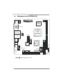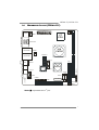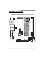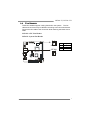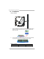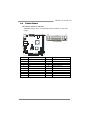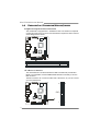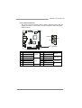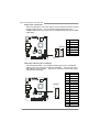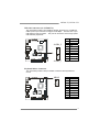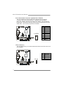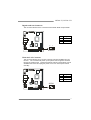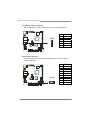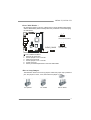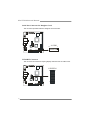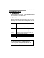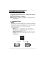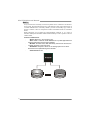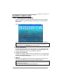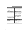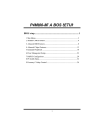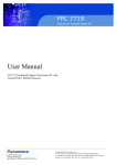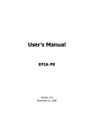
1
CN700-I7/CN700-I7C Setup Manual FCC Information and Copyright This equipment has been tested and found to comply with the limits of a Class B digital device, pursuant to Part 15 of the FCC Rules. These limits are designed to provide reasonable protection against harmful interference in a residential installation. This equipment generates, uses and can radiate radio frequency energy and, if not installed and used in accordance with the instructions, may cause harmful interference to radio communications. There is no guarantee that interference will not occur in a particular installation. The vendor makes no representations or warranties with respect to the contents here and specially disclaims any implied warranties of merchantability or fitness for any purpose. Further the vendor reserves the right to revise this publication and to make changes to the contents here without obligation to notify any party beforehand. Duplication of this publication, in part or in whole, is not allowed without first obtaining the vendor’s approval in writing. The content of this user’s manual is subject to be changed without notice and we will not be responsible for any mistakes found in this user’s manual. All the brand and product names are trademarks of their respective companies. Table of Contents Chapter 1: Introduction.......................................... 3 1.1 1.2 1.3 1.4 1.5 1.6 Before You Start ............................................................................ 3 Package Checklist......................................................................... 3 Mainboard Specifications.............................................................. 4 Rear Panel..................................................................................... 5 Mainboard Layout (CN700-I7).................................................... 6 Mainboard Layout (CN700-I7C) ................................................. 7 Chapter 2: Installation ........................................... 8 2.1 2.2 2.3 2.4 2.5 CPU ................................................................................................ 8 Fan Headers .................................................................................. 9 System Memory ........................................................................... 10 Power Supply............................................................................... 11 Onboard Slot/Connector/Header/Jumper.................................. 12 Chapter 3: BIOS Setup ......................................... 21 3.1 3.2 3.3 3.4 3.5 3.6 3.7 3.8 3.9 3.10 3.11 Entering Setup............................................................................. 21 Using Setup .................................................................................. 21 Main Menu................................................................................... 22 Standard CMOS Features............................................................ 25 Advanced BIOS Features ............................................................ 27 Advanced Chipset Features........................................................ 32 Integrated Peripherals ............................................................... 39 Power Management Setup ......................................................... 44 PnP/PCI Configurations ............................................................. 50 PC Health Status ......................................................................... 52 Frequency/Voltage Control ........................................................ 55 Chapter 4: RAID Functions ................................... 57 4.1 4.2 4.3 Operation System........................................................................ 57 Raid Arrays.................................................................................. 57 How RAID Works......................................................................... 57 Chapter 5: Useful Help ......................................... 59 5.1 5.2 5.3 5.4 Driver Installation Note.............................................................. 59 Phoenix-Award BIOS Beep Code ............................................... 60 Extra Information ....................................................................... 60 Troubleshooting........................................................................... 62 CN700-I7/CN700-I7C CHAPTER 1: INTRODUCTION 1.1 BEFORE YOU START Thank you for choosing our product. Before you start installing the mainboard, please make sure you follow the instructions below: Prepare a dry and stable working environment with sufficient lighting. Always disconnect the system from power outlet before operation. Before you take the mainboard out from anti-static bag, ground yourself properly by touching any safely grounded appliance, or use grounded wrist strap to remove the static charge. Avoid touching the components on mainboard or the rear side of the board unless necessary. Hold the board on the edge, do not try to bend or flex the board. 1.2 Do not leave any unfastened small parts inside the case after installation. Loose parts will cause short circuits which may damage the equipment. Keep the system from dangerous area, such as heat source, humid air, and water. PACKAGE CHECKLIST Mini-ITX Mainboard X 1 HDD Cable X 1 User’s Manual X 1 Fully Setup Driver CD X 1 I/O Bracket X 1 SATA Cable X 1 (Optional) Quick Installation Guide X 1 (Optional) 3 Mini-ITX Mainboard Manual 1.3 MAINBOARD SPECIFICATIONS CN700-I7 CPU FSB On-Board VIA CPU C7-D / C7 / Eden / Eden-ULV series (up to 2.0GHz) Eden-ULV series (up to 2.0GHz) V4 bus NanoBGA2 V4 bus NanoBGA2 Supports Power Saving Supports Power Saving 400 MHz 400 MHz VIA CN700 VIA CN700 VIA VT8237R Plus VIA VT8237R Plus VIA UniChromePro VIA UniChromePro VIA VT1625M TV-Out HDTV encoder VIA VT1625M TV-Out HDTV encoder Max Shared Video Memory is 64 MB Max Shared Video Memory is 64 MB Winbond W83697 ITE 8712 Provides the most commonly used legacy Provides the most commonly used legacy Super I/O functionality. Super I/O functionality. Super I/O Low Pin Count Interface Low Pin Count Interface Chipset Graphic Main Memory IDE SATA LAN PHY Sound Codec 4 CN700-I7C On-Board VIA CPU C7-D / C7 / Eden / Environment Control initiatives, Environment Control initiatives, H/W Monitor H/W Monitor Fan Speed Controller Fan Speed Controller DDR2 DIMM Slot x 1 DDR2 DIMM Slot x 1 Supports DDR2 400 / 533 Supports DDR2 400 / 533 Each DIMM supports 256/512MB/1GB Each DIMM supports 256/512MB/1GB DDR2 DDR2 Max Memory Capicity 1GB Max Memory Capicity 1GB Single Channel Mode DDR2 memory Single Channel Mode DDR2 memory module module Registered DIMM and ECC DIMM is not Registered DIMM and ECC DIMM is not supported supported VIA VT8237R Plus VIA VT8237R Plus Ultra DMA 33~133 Bus Master Mode Ultra DMA 33~133 Bus Master Mode Supports PIO Mode 0~4 Supports PIO Mode 0~4 Supports 2 IDE devices Supports 2 IDE devices VIA VT8237R Plus VIA VT8237R Plus SATA Version 1.0 specification compliant. SATA Version 1.0 specification compliant. Data transfer rates up to 1.5 Gb/s. Data transfer rates up to 1.5 Gb/s. Supports RAID 0 / 1 Supports RAID 0 / 1 VIA VT6103L (PHY) VIA VT6103L (PHY) VIA VT6107 (PCI) VIA VT6107 (PCI) 10 / 100 Mb/s auto negotiation 10 / 100 Mb/s auto negotiation Half / Full duplex capability Half / Full duplex capability VIA VT1618 VIA VT1618 6 channels audio out 6 channels audio out AC=97 AC=97 Slots 32-Bit PCI slot x1 32-Bit PCI slot x1 On Board IDE Connector x1 IDE Connector x1 Connector KB/MS Connector x1 KB/MS Connector x1 CN700-I7/CN700-I7C CN700-I7 Back Panel I/O Board Size OS Support CN700-I7C SATA Connector x2 SATA Connector x2 Serial Header x1 Serial Header x1 COM Port for Daughter card x1 COM Port for Daughter card x1 Front Panel Connector x1 Front Panel Connector x1 Front Audio Connector(Optional) x1 Front Audio Connector x1 CD-in Connector x1 CD-in Connector x1 S/PDIF out connector x1 S/PDIF out Connector x1 CPU Fan header x1 CPU Fan header x1 System Fan header x1 System Fan header x1 Clear CMOS header x1 Clear CMOS header x1 USB 2.0 connector x1 USB 2.0 Connector x2 Component video pin header x1 Component video pin header x1 Wake on LAN header x1 Wake on LAN header x1 LVDS/DVI Connector x1 LVDS/DVI Connector x1 Power Connector (20pin) x1 Power Connector (20pin) x1 PS/2 Keyboard x1 PS/2 Keyboard x1 PS/2 Mouse x1 PS/2 Mouse x1 Serial Port x1 Serial Port x1 VGA Port x1 VGA Port x1 LAN port x2 LAN port x2 USB Port x4 USB Port x4 RCA Port x1 RCA Port x1 S-Video Port x1 S-Video Port x1 Audio Jack x3 Audio Jack x3 170 mm (W) x 170 mm (L) 170 mm (W) x 170 mm (L) Mini-ITX Mini-ITX Windows XP / Linux Windows XP / Linux Biostar Reserves the right to add or remove Biostar Reserves the right to add or remove support for any OS with or without notice. support for any OS with or without notice. 1.4 REAR PANEL PS/2 Mouse COM Port LAN LAN RCA Line Out (Front) PS/2 Keyboard VGA USB 2.0X4 S-Video Mic In (Center/SUB) Line In (Rear) 5 Mini-ITX Mainboard Manual 1.5 MAINBOARD LAYOUT (CN700-I7) JKBMS1 KBMS JATXPWR1 C7 CPU JCFAN1 JCOM-VGA VIA CN700 JSFAN1 DIMM1 JRJ45USB1 LVDS-DVI JRJ45USB2 USB4-7 IDE1 YPBPR VIA VT8237R+ BIOS F_PANEL CN1 CD_IN SATA2 JAUDIO1 J_AUDIO(Optional) SPDIFO SATA1 JCOM2 4-COM PCI1 Note: ■ represents the 1st pin. 6 BATTERY JWOL1 CLEAR_ CMOS CN700-I7/CN700-I7C 1.6 MAINBOARD LAYOUT (CN700-I7C) JKBMS1 KBMS JATXPWR1 C7 CPU JCFAN1 JCOM-VGA VIA CN700 JSFAN1 DIMM1 JRJ45USB1 LVDS-DVI JRJ45USB2 JUSB4_5 IDE1 YPBPR BIOS VIA VT8237R+ JUSB6_7 F_PANEL CN1 CD_IN SATA2 JAUDIO1 J_AUDIO SPDIFO SATA1 JCOM2 4-COM PCI1 BATTERY JWOL1 CLEAR_ CMOS Note: ■ represents the 1st pin. 7 Mini-ITX Mainboard Manual CHAPTER 2: INSTALLATION 2.1 CPU The mainboard includes an embedded VIA V4 Bus processor and a heatsink has been installed to provide sufficient cooling. C7 CPU VIA CN700 VIA VT8237R+ 8 CN700-I7/CN700-I7C 2.2 FAN HEADERS These fan headers support cooling-fans built in the system. The fan cable and connector may be different according to the fan manufacturer. Connect the fan cable to the connector while matching the black wire to GND. JCFAN1: CPU Fan Header JSFAN1: System Fan Header 3 1 Pin JCFAN1 JSFAN1 Assignment 1 FAN_MCM 2 Smart_Fan 3 GND 1 3 9 Mini-ITX Mainboard Manual 2.3 SYSTEM MEMORY DIMM1 Memory Modules 1. Unlock a DIMM slot by pressing the retaining clips outward. Align a DIMM on the slot such that the notch on the DIMM matches the break on the Slot. 2. Insert the DIMM vertically and firmly into the slot until the retaining chip snap back in place and the DIMM is properly seated. Memory Capacity DIMM Socket Location DIMM1 10 DDR2 Module 256MB/512MB/1GB Total Memory Size Max is 1GB. CN700-I7/CN700-I7C 2.4 POWER SUPPLY ATX Power Source Connector JATXPWR1 allows user to connect 20-pin power connector on the power supply. 20 10 Pin 11 JATXPWR1 Assignment Pin Assignment +3.3V 11 +3.3V 2 +3.3V 12 -12V 3 GND 13 GND 4 +5V 14 Power Supply On 5 GND 15 GND 1 6 +5V 16 GND 7 GND 17 GND 8 Power Good 18 NC 9 +5V Standby 19 +5V 10 +12V 20 +5V 1 11 Mini-ITX Mainboard Manual 2.5 ONBOARD SLOT/CONNECTOR/HEADER/JUMPER Peripheral Component Interconnect Slot This mainboard is equipped with 1 standard PCI slot. PCI stands for Peripheral Component Interconnect, and it is a bus standard for expansion cards. This PCI slot is designated as 32 bits. PCI1 ATA Device Connector The mainboard has a 32-bit Enhanced PCI IDE Controller that provides PIO Mode 0~4, Bus Master, and Ultra DMA 33/66/100/133 functionality. It has one IDE connector. The IDE connector can connect a master and a slave drive, so you can connect up to two ATA devices. 40 39 IDE1 2 12 1 CN700-I7/CN700-I7C Front Panel Connector This 16-pin connector includes Power-on, Reset, HDD LED, Power LED, and speaker connection. It allows user to connect the system case’s front panel switch functions. + POW-LED 1 2 + HLED ON/OFF + SPK RST + NA 15 16 F_PANEL Pin Assignment 1 +5VDUAL 3 +5VDUAL 5 7 9 NC 11 NC 13 15 Function Pin Assignment 2 +5V 4 HD_LED -PLED 6 PW_BN +5V 8 GND 10 RST_SW 12 GND SPEAK 14 +5V Key 16 NC Power LED Speaker Function HDD LED Power Switch Reset Switch N/A 13 Mini-ITX Mainboard Manual Serial ATA Connectors These next generation connectors support the thin Serial ATA cables for primary internal storage devices. The current Serial ATA interface allows up to 150MB/s data transfer rate, faster than the standard parallel ATA with 133 MB/s (Ultra DMA). Pin SATA2 1 4 7 Assignment 1 GND 2 TX+ 3 TX- 4 GND 5 RX- 6 RX+ 7 GND SATA1 USB 2.0 Connector (for CN700-I7) The mainboard provides 1 front USB pin header, allowing up to 4 additional USB2.0 ports up to maximum throughput of 480 Mbps. Connect each 2-port USB cable into this pin header. This port can be used to connect high-speed USB interface peripherals. Pin USB4-7 16 2 14 15 1 Assignment 1 GND 2 Key 3 GND 4 GND 5 USBD_T6+ 6 USBD_T7+ 7 USBD_T6- 8 USBD_T7- 9 USBVCC 10 USBVCC 11 USBD_T4- 12 USBD_T5- 13 USBD_T4+ 14 USBD_T5+ 15 GND 16 GND CN700-I7/CN700-I7C USB 2.0 Connectors (for CN700-I7C) The mainboard provides 2 front USB pin headers, allowing up to 4 additional USB2.0 ports up to maximum throughput of 480 Mbps. Connect each 2-port USB cable into this pin header. This port can be used to connect high-speed USB interface peripherals. Pin JUSB4_5 1 2 10 Assignment 1 +5V (fused) 2 +5V (fused) 3 USB- 4 USB- 5 USB+ 6 USB+ 7 Ground 8 Ground 9 Key 10 NC JUSB6_7 Keyboard/Mouse Connector The mainboard provides a PS2 pin header to attach a PS2 keyboard and mouse. KBMS 1 9 2 10 Pin 1 Assignment +5V_Dual 2 GND 3 KB_CLK 4 KB_DATA 5 EKBCLK 6 EKBDATA 7 Mouse_CLK 8 Mouse_DATA 9 EMSCLK 10 EMSDATA 15 Mini-ITX Mainboard Manual Front Panel Audio Connector (Optional for CN700-I7) This is an interface for the front panel audio cable that allow convenient connection and control of audio devices. By default, the pins labeled LINE_OUT_R/NEXT_R and the pins LINE_OUT_L/NEXT_L are shorted with jumper caps. Remove the caps only when you are connecting the front panel audio cable. This connector is optional for CN700-I7. Pin 1 J_AUDIO 1 9 2 10 Assignment FRNMIC_L 2 AGND 3 FRNMIC_R 4 +3.3V_AUDIO 5 LINE_OUT_R 6 NEXT_R 7 NC 8 Key 9 LINE_OUT_L 10 NEXT_L CD-in Connector This pin header allows you to receive stereo audio input from sound source such as a CD-ROM. CD_IN 1 4 16 Pin Assignment 1 Left_Channel 2 GND 3 GND 4 Right_Channel CN700-I7/CN700-I7C Digital Audio-out Connector This connector allows user to connect the PCI bracket SPDIF output header. Pin 3 Assignment 1 +5V 2 SPIDF_OUT 3 GND 1 SPDIFO Wake-On LAN Connector This connector allows you to connect a network card with the Wake-On LAN function. The connector will power up the system when a signal is received through the network card. Please note that the function of ACPI WOL may be disabled when users will unplug the power cord or turn off the power button manually. Pin 1 Assignment +5VSUS 2 GND 3 WOL_IN JWOL1 3 1 17 Mini-ITX Mainboard Manual Component Video Connector This pin header is for YPbPr (Component TV output connector) signals. Pin YPBPR 6 1 1 Assignment NC 2 VDD 3 Pr 4 Y 5 Pb 6 GND Serial Port Connector COM2 pin header can be used to attach additional port for serial mouse or another serial device. Pin 1 JCOM2 9 10 18 1 2 Assignment DCD 2 DSR 3 SIN 4 RTS 5 SOUT 6 CTS 7 DTR 8 RI 9 GND 10 Key CN700-I7/CN700-I7C Clear CMOS Header * By placing the jumper on pin2-3, it allows user to restore the BIOS safe setting and the CMOS data, please carefully follow the procedures to avoid damaging the mainboard. 1 3 Pin 1-2 Close: Normal Operation(default). 1 CLEAR_CMOS 1 ※ 1. 2. 3. 4. 5. 6. 3 Pin 2-3 Close: Clear CMOS data. 3 Clear CMOS Procedures: Remove AC power line. Set the jumper to “Pin 2-3 close”. Wait for five seconds. Set the jumper to “Pin 1-2 close”. Power on the AC. Reset your desired password or clear the CMOS data. *How to Setup Jumpers The illustration shows how to set up jumpers. When the jumper cap is placed on pins, the jumper is “close”, if not, that means the jumper is “open”. Pin opened Pin closed Pin1-2 closed 19 Mini-ITX Mainboard Manual Serial Port Connector for Daughter Card This connector provides extension daughter card connection. 17 4-COM 18 1 2 LVDS/DVI Connector This connector is for devices requiring display interface such as LVDS or DVI. LVDS/DVI 20 50 49 2 1 CN700-I7/CN700-I7C CHAPTER 3: BIOS SETUP 3.1 ENTERING SETUP Power on the system and press <Delete> during the beginning of the boot sequence to enter the BIOS setup menu. If you missed the BIOS setup entry point, you may restart the system and try again. 3.2 USING SETUP Use the arrow keys to highlight items in most of the place, press <Enter> to select, use the <PgUp> and <PgDn> keys to change entries, press <F1> for help and press <Esc> to quit. The following table provides more detail about how to navigate in the Setup program by using the keyboard. Keystroke Function Up arrow Move to previous item Down arrow Move to next item Left arrow Move to the item on the left (menu bar) Right arrow Move to the item on the right (menu bar) Move Enter Move to the item you desired PgUp key Increase the numeric value or make changes PgDn key Decrease the numeric value or make changes + Key Increase the numeric value or make changes - Key Decrease the numeric value or make changes Main Menu – Quit and not save changes into CMOS Esc key Status Page Setup Menu and Option Page Setup Menu – Exit Current page and return to Main Menu F1 key General help on Setup navigation keys F5 key Load previous values from CMOS F7 key Load the optimized defaults F10 key Save all the CMOS changes and exit !! WARNING !! For better system performance, the BIOS firmware is being continuously updated. The BIOS information described in this manual is for your reference only. The actual BIOS information and settings on board may be slightly different from this manual. 21 Mini-ITX Mainboard Manual 3.3 MAIN MENU Once you enter Phoenix-Award BIOS™ CMOS Setup Utility, the Main Menu will appear on the screen. The Main Menu allows you to select from several setup functions. Use the arrow keys to select among the items and press <Enter> to accept and enter the sub-menu. Standard CMOS Features This submenu contains industry standard configurable options. Advanced BIOS Features This submenu allows you to configure advanced features of the BIOS. Advanced Chipset Features This submenu allows you to configure special chipset features. Integrated Peripherals This submenu allows you to configure certain IDE hard drive options and Programmed Input/ Output features. Power Management Setup This submenu allows you to configure the power management features. 22 CN700-I7/CN700-I7C PnP/PCI Configurations This submenu allows you to configure certain “Plug and Play” and PCI options. PC Health Status This submenu allows you to monitor the hardware of your system. Frequency/Voltage Control This submenu allows you to change CPU Vcore Voltage and CPU/PCI clock. (However, we suggest you to use the default setting. Changing the voltage and clock improperly may damage the CPU or M/B!) Load Optimized Defaults This selection allows you to reload the BIOS when problem occurs during system booting sequence. These configurations are factory settings optimized for this system. A confirmation message will be displayed before defaults are set. Set Supervisor Password Setting the supervisor password will prohibit everyone except the supervisor from making changes using the CMOS Setup Utility. You will be prompted with to enter a password. 23 Mini-ITX Mainboard Manual Set User Password If the Supervisor Password is not set, then the User Password will function in the same way as the Supervisor Password. If the Supervisor Password is set and the User Password is set, the “User” will only be able to view configurations but will not be able to change them. Save & Exit Setup Save all configuration changes to CMOS (memory) and exit setup. Confirmation message will be displayed before proceeding. Exit Without Saving Abandon all changes made during the current session and exit setup. Confirmation message will be displayed before proceeding. Upgrade BIOS This submenu allows you to upgrade bios. 24 CN700-I7/CN700-I7C 3.4 STANDARD CMOS FEATURES Selections This table shows the items and the available options on the menu of Standard CMOS Features. Item Options Description Set the system date. Note Date mm : dd : yy that the ‘Day’ automatically changes when you set the date. Time IDE Channel 0 Master IDE Channel 0 Slave hh : mm : ss Options are in its sub menu. Options are in its sub menu. SATA Channel 1 Options are in its sub Master menu. Set the system internal clock. Press <Enter> to enter the sub menu of detailed options Press <Enter> to enter the sub menu of detailed options. Press <Enter> to enter the sub menu of detailed options. 25 Mini-ITX Mainboard Manual Item Options SATA Channel 2 Options are in its sub Master menu. Description Press <Enter> to enter the sub menu of detailed options. EGA/VGA Video CGA 40 Select the default video CGA 80 device. MONO All Errors Halt On No Errors All, but Keyboard Select the situation in which you want the BIOS to stop the POST process and notify you. Displays the amount of Base Memory N/A conventional memory detected during boot up. Displays the amount of Extended Memory N/A extended memory detected during boot up. Total Memory 26 N/A Displays the total memory available in the system. CN700-I7/CN700-I7C 3.5 ADVANCED BIOS FEATURES CPU Features Delay Prior to Thermal This option controls the activation of the Thermal Monitor's automatic mode. It allows you to determine when the Thermal Monitor should be activated in automatic mode after the system boots. The Choices: 4 Min / 8 Min / 16 Min (Default) / 32 Min 27 Mini-ITX Mainboard Manual Thermal Management This option allows you to select the way to control the “Thermal Management.” The Choices: Thermal Monitor 1(Default) / Thermal Monitor 2 TM2 Bus Ratio This option sets the frequency (bus ratio) of the throttled performance that will be initiated when the on die sensor goes from not hot to hot. Min=8, Max=10, key in a DEC number. The Choices: 10X (Default) TM2 Bus VID This option sets the voltage of the throttled performance that will be initiated when the on die sensor goes from not hot to hot. The Choices: 0.700~1.084 with a interval of 0.016 / 1.084V (Default) Hard Disk Boot Priority This is for setting the priority of the hard disk boot order when the “Hard Disk” option is selected in the “[First/Second/Third] Boot Device” menu item. The Choices: Ch0 M.(Channel 0 Master) / Bootable Add-in Cards 28 CN700-I7/CN700-I7C Virus Warning This option allows you to choose the VIRUS Warning feature that is used to protect the IDE Hard Disk boot sector. If this function is enabled and an attempt is made to write to the boot sector, BIOS will display a warning message on the screen and sound an alarm beep. The Choices: Enabled / Disabled (Default) CPU L1 & L2 Cache Depending on the CPU/chipset in use, you may be able to increase memory access time with this option. The Choices: Enabled (Default) / Disabled CPU L2 Cache ECC Checking This item allows you to enable/disable CPU L2 Cache ECC Checking. The Choices: Enabled (Default) / Disabled. Quick Power On Self Test Enabling this option will cause an abridged version of the Power On Self-Test (POST) to execute after you power up the computer. The Choices: Disabled Normal POST. Enabled (Default) Enable quick POST. First / Second / Third Boot Device The BIOS will attempt to load the operating system in this order. The Choices: LS120 / Hard Disk / CDROM / ZIP100 / USB-FDD / USB-ZIP / USB-CDROM / Legacy LAN / Disabled Boot Other Device When enabled, BIOS will try to load the operating system from other device when it failed to load from the three devices above. The Choices: Enabled (Default) / Disabled 29 Mini-ITX Mainboard Manual Boot Up NumLock Status Selects the NumLock State after the system switched on. The Choices: The Choices: On (Default) Numpad is number keys. Off Numpad is arrow keys. Typematic Rate Setting When a key is held down, the keystroke will repeat at a rate determined by the keyboard controller. When enabled, the typematic rate and typematic delay can be configured. The Choices: Disabled (Default) / Enabled Typematic Rate (Chars/Sec) Sets the rate at which a keystroke is repeated when you hold the key down. The Choices: 6 (Default) / 8 / 10 / 12 / 15 / 20 / 24 / 30 (This option can be set only when “Typematic Rate Setting” is enabled.) Typematic Delay (Msec) Sets the delay time after the key is held down before it begins to repeat the keystroke. The Choices: 250 (Default) / 500 / 750 / 1000 (This option can be set only when “Typematic Rate Setting” is enabled.) Security Option This option will enable only individuals with passwords to bring the system online and/or to use the CMOS Setup Utility. The Coices: System: A password is required for the system to boot and is also required to access the Setup Utility. Setup (default): A password is required to access the Setup Utility only. This will only apply if passwords are set from the Setup main menu. 30 CN700-I7/CN700-I7C MPS Version Control For OS The BIOS supports version 1.1 and 1.4 of the Intel multiprocessor specification. Select version supported by the operation system running on this computer. The Choices: 1.4 (Default) / 1.1 OS Select For DRAM > 64MB A choice other than Non-OS2 is only used for OS2 systems with memory exceeding 64MB. The Choices: Non-OS2 (Default) / OS2 Video BIOS Shadow Determines whether video BIOS will be copied to RAM for faster execution or not. The Choices: Enabled (default) Optional ROM is enabled. Disabled Optional ROM is disabled. Small Logo(EPA) Show This item allows you to select whether the “Small Logo” shows. Enabled (default) “Small Logo” shows when system boots up. Disabled No “Small Logo” shows when system boots The Choices: Disabled (Default) / Enabled Summary Screen Show This item allows you to enable/disable the summary screen. screen means system configuration and PCI device listing. The Choices: Disabled (Default) / Enabled Summary 31 Mini-ITX Mainboard Manual 3.6 ADVANCED CHIPSET FEATURES DRAM Clock/Drive Control DRAM Clock This item determines DRAM clock. The Choices: By SPD (Default) / 200MHz / 266MHz 32 CN700-I7/CN700-I7C DRAM Timing This item determines DRAM clock/ timing. The Choices: Auto by SPD (Default) / Manual SDRAM CAS Latency [DDR/DDR2] When DRAM is installed, the number of clock cycles of CAS latency depends on the DRAM timing. The Choices: 2.5/4(Default) / 1.5/2 / 2/3 / 3/5 Bank Interleave This item allows you to enable or disable the bank interleave feature. The Choices: Disabled (Default) / 2 Bank / 4 Bank / 8 Bank Precharge to Active (Trp) This item allows you to specify the delay from precharge command to activate command. The Choices: 4T (Default) / 2T / 3T / 5T Active to Precharge (Tras) This item allows you to specify the minimum row active time (TRAS). The Choices: 07T (Default) / 05T~20T Active to CMD (Trcd) Use this item to specify the delay from the activation of a bank to the time that a read or write command is accepted. The Choices: 4T (Default) / 2T / 3T / 5T REF to ACT/REF (Trfc) This item allows you to determine the selection for REF to ACT/REF to REF (TRFC). The Choices: 21T (Default) / 08T~71T ACT (0) to ACT (1) (TRRD) This item allows you to determine the selection for ACT (0) to ACT (1) (TRRD) The Choices: 3T (Default) / 2T / 4T / 5T 33 Mini-ITX Mainboard Manual Read to Precharge (Trtp) This item allows you to determine the selection for Read to Precharge (TRTP) The Choices: 2T (Default) / 3T Write to Read CMD (Twtr) This item allows you to determine the selection for Write to Read CMD (TWTR) The Choices: 1T/2T (Default) / 2T/3T Write Recovery Time (Twr) This item allows you to determine the selection for Read to Precharge (TRTP) The Choices: 4T (Default) / 2T / 3T / 5T DRAM Command Rate This field is for setting how fast the memory controller sends out commands. Lower setting equals faster command rate. NOTE: Some memory modules may not be able to handle lower settings. The Choices: 2T Command (Default) / 1T Command RDSAIT mode This option allows you to choose the way RDSAIT works. The Choices: Auto (Default) / Manual RDSAIT selection Min=0000, Max=003F, key in a HEX number. The Choices: 03 (Default) 34 CN700-I7/CN700-I7C AGP & P2P Bridge Control AGP Aperture Size This setting controls how much memory space can be allocated to AGP for video purposes. The aperture is a portion of the PCI memory address range dedicated to graphics memory address space. Host cycles that hit the aperture range are forwarded to the AGP without any translation. The Choices: 128M (Default) / 32M / 64M / 256M / 512M / 1G AGP Driving Control This item is used to signal driving current on AGP cards to auto or manual. The Choices: Auto (Default) / Manual AGP Driving Value Min=0000, Max=00FF, key in a HEX number. The Choices: DA (Default) AGP Fast Write This item is used to enable or disable the caching of display data for the video memory of the processor. The Choices: Disabled (Default) / Enabled 35 Mini-ITX Mainboard Manual AGP Master 1 WS Write/Read This item is used to enable or disable the AGP Master 1 WS Write/Read function. The Choices: Enabled (Default) / Disabled AGP 3.0 Calibration Cycle The Choices: Disabled (Default) / Enabled VGA Share Memory Size This item allows you to select the VGA share memory size. The Choices: 64M (Default) / 16M / 32M / Disabled Direct Frame Buffer This item allows you to disabled or enabled direct frame buffer. The Choices: Enabled (Default) / Disabled Select Display Device This option allows you to select to display device. The Choices: CRT (Default) / TV / DVI / CRT+TV / CRT+DVI / TV+DVI Panel Type This option allows you to select to type of the panel. Min=0000, Max=000F, key in a HEX number. The Choices: 07 (Default) Outport Port This option allows you to select to type of out-port. The Choices: DI0 (Default) / DI1 Dithering This option allows you turn on/off the dithering function. The Choices: Disabled (Default) / Enabled TV_Layout This option allows you select the type of TV layout. The Choices: Default (Default) / COMP.+S-Video / COMPOSITE / S-Video 36 CN700-I7/CN700-I7C TV_type This option allows you select the type of TV. The Choices: NTSC (Default) / PAL/PAL B/PAL G/PAL H / PALM / PALN / PALNc / PAL I / PAL D / NTSC Japan TV_Connector This option allows you select the type of TV connector. The Choices: CVBS+S-Video (Default) / CVBS / S-Video 0 / SDTV-Pr/Y/Pb CPU & PCI Bus Control PCI Master 0 WS Write When enabled, writes to the PCI bus are executed with zero-wait states. The Choices: Enabled (Default) / Disabled PCI Delay Transaction The chipset has an embedded 32-bit posted write buffer to support delay transactions cycles. Select Enabled to support compliance with PCI specification. The Choices: Enabled (Default) / Disabled 37 Mini-ITX Mainboard Manual VLink mode selection This menu item controls the data transfer speed between the north and south bridge. The Choices: By Auto (Default) / Mode 0 / Mode 1 VLink 8X Support This item allows you to enable or disable VLink 8X support. The Choices: Enabled (Default) / Disabled DRDY_Timing The Choices: Default (Default) / Slowest / Optimize Memory Hole You can reserve this area of system memory for ISA adapter ROM. When this area is reserved it cannot be cached. Check the user information of peripherals that need to use this area of system memory for the memory requirements. The Choices: Disabled (Default) / 15M-16M System BIOS Cacheable Selecting the “Enabled” option allows caching of the system BIOS ROM at F0000h-FFFFFh, which is able to improve the system performance. However, any programs that attempts to write to this memory block will cause conflicts and result in system errors. The Choices: Enabled (Default) / Disabled Video RAM Cacheable This option allows you to turn on/off the video ram cacheable function. The Choices: Disabled (Default) / Enabled Init Display First This option allows you to select the initial slot for display card. The Choices: PCI Slot (Default) / AGP 38 CN700-I7/CN700-I7C 3.7 INTEGRATED PERIPHERALS VIA OnChip IDE Device OnChip SATA This option allows you to enable the on-chip Serial ATA. The Choices: Enabled (Default) / Disabled 39 Mini-ITX Mainboard Manual SATA Mode This option allows you to select SATA Mode. The Choices: IDE (Default) / RAID IDE DMA transfer Access This item allows you to enable or disable the IDE DMA transfer access. The Choices: Enabled (Default) / Disabled OnChip IDE Channel 0 The motherboard chipset contains a PCI IDE interface with support for one IDE channel. Select “Enabled” to activate the IDE interface. Select “Disabled” to deactivate the interface if you are going to install a add-in IDE interface. The Choices: Enabled (Default) / Disabled IDE Prefetch Mode The “onboard” IDE drive interfaces supports IDE prefetch function for faster drive access. If the interface on your drive does not support prefetching, or if you install a add-in IDE interface, set this option to “Disabled”. The Choices: Enabled (Default) / Disabled. Primary Master/Slave PIO The IDE PIO (Programmed Input / Output) fields let you set a PIO mode (0-4) for each of the IDE devices that the onboard IDE interface supports. Modes 0 to 4 will increase performance progressively. In Auto mode, the system automatically determines the best mode for each device. The Choices: Auto (Default) / Mode0 / Mode1 / Mode2 / Mode3 / Mode4 Primary Master/Slave UDMA Ultra DMA function can be implemented if it is supported by the IDE hard drives in your system. As well, your operating environment requires a DMA driver (Windows 95 or OSR2may need a third party IDE bus master driver). If your hard drive and your system software both support Ultra DMA, select Auto to enable BIOS support. The Choices: Auto (Default) / Disabled 40 CN700-I7/CN700-I7C IDE HDD Block Mode Block mode is also called block transfer, multiple commands, or multiple sectors read / write. If your IDE hard drive supports block mode (most new drives do), select Enabled for automatic detection of the optimal number of block mode (most new drives do), select Enabled for automatic detection of the optimal number of block read / write per sector where the drive can support. The Choices: Enabled (Default) / Disabled VIA OnChip PCI Device VIA-3058 AC97 Audio Auto allows the mainboard to detect whether an audio device is used. If the device is detected, the onboard VIA AC'97 (Audio Codec'97) controller will be enabled; otherwise, it is disabled. Disable the controller if another controller card is being used to connect to an audio device. The Choices: Auto (Default) / Disabled VIA-3043 OnChip LAN This option allows you to control the onboard LAN. The Choices: Enabled (Default) / Disabled Onboard Lan Boot ROM Decide whether to invoke the boot ROM of the onboard LAN chip. The Choices: Disable (Default) / Enabled 41 Mini-ITX Mainboard Manual OnChip USB Controller This option allows you to control the onboard USB. The Choices: All Enabled (Default) / All Disabled / 1&2 USB Port / 2&3 USB Port / 1&3 USB Port / 1 USB Port / 2 USB Port / 3 USB Port OnChip EHCI Controller This option allows you to control the onboard EHCI. The Choices: Enabled (Default) / Disabled USB Emulation Set this field to choose the USB emulation. When set to ¡§OFF ¡§, do not support any USB device on DOS. When set to “KB/MS”, support USB legacy keyboard and mouse, no support USB storage. And set to “ON”, support USB legacy keyboard, mouse and storage. The Choices: ON (Default) / OFF / KB/MS USB Keyboard/Mouse Support These options activate only when “USB Emulation” is set to “KB/MS”. The Choices: Enabled (Default) / Disabled 42 CN700-I7/CN700-I7C SuperIO Device Onboard Serial Port 1 / 2 Select an address and corresponding interrupt for the first and second serial ports. The Choices: 3F8/IRQ4 / Disabled / 2F8/IRQ3 / 3E8/IRQ4 / 2E8/IRQ3 / Auto Serial Port 3 / 4 / 5 / 6 Use IRQ Select an interrupt for the third/fourth/fifth/sixth serial ports. The Choices: IRQ5 / IRQ7 / IRQ10 / IRQ11 Onboard Serial Port 3 / 4 Select an address for the third/fourth serial ports. The Choices: 3F8 / 2F8 / 3E8 / 2E8 Onboard Serial Port 5 / 6 Select an address for the fifth/sixth serial ports. The Choices: 4F8 / 4E8 CIR Port Address (Only for CN700-I7C) This option allows you to set the CIR port address. The Choices: 310 (Default) / 320 / Disabled. 43 Mini-ITX Mainboard Manual CIR Port IRQ (Only for CN700-I7C) This option allows you to set the CIR port IRQ. The Choices: 11 (Default) / 5. 3.8 POWER MANAGEMENT SETUP ACPI Function This item displays the status of the Advanced Configuration and Power Management (ACPI). The Choices: Enabled (Default) / Disabled. ACPI Suspend Type The item allows you to select the suspend type under the ACPI operating system. The Choices: S1 (POS) (Default) Power on Suspend S3 (STR) Suspend to RAM S1&S3 POS+STR 44 CN700-I7/CN700-I7C Power Management Option This category allows you to select the power saving method and is directly related to the following modes: 1. HDD Power Down. 2. Suspend Mode. There are three options of Power Management, three of which have fixed mode settings. The Choices: Min Saving Minimum power management. Suspend Mode = 1 hr. HDD Power Down = Disable Max Saving Maximum power management only available for sl CPU’s. Suspend Mode = 1 min. HDD Power Down = Disable User Define (Default) Allow you to set each option individually. When you choose user define, you can adjust each of the item from 1 min. to 1 hr. except for HDD Power Down which ranges from 1 min. to 15 min. HDD Power Down When enabled, the hard-disk drives will power down after a set time of system inactivity. All other devices remain active. The Choices: Disabled (Default) / 1 Min~15Min Suspend Mode The item allows you to adjust the system idle time before suspend. The Choices: Disabled (Default) / 1 Min / 2 Min / 4 Min / 6 Min / 8 Min / 10 Min / 20 Min / 30 Min / 40 Min / 1 Hour Video Off Option This field determines when to activate the video off feature for monitor power management. The Choices: Suspend→Off (Default) / Always on 45 Mini-ITX Mainboard Manual Video Off Method This option determines the manner when the monitor goes blank. The Choices: V/H SYNC+Blank (Default) This selection will cause the system to turn off the vertical and horizontal synchronization ports and write blanks to the video buffer. Blank Screen This option only writes blanks to the video buffer. DPMS Support Initial display power management signaling. Modem Use IRQ This determines the IRQ, which can be applied in MODEM use. The Choices: 3 (Default) / 4 / 5 / 7 / 9 / 10 / 11 / NA Soft-Off by PWRBTN This item determines the behavior of system power button. Instant off turn off the power immediately, and Delay 4 Sec. will require you to press and hold the power button for 4 seconds to cut off the system power. The Choices: Delay 4 Sec / Instant-Off (Default) Run VGABIOS if S3 Resume Choosing Enabled will make BIOS run VGA BIOS to initialize the VGA card when system wakes up from S3 state. The system resume time is shortened if you disable the function, but system will need AGP driver to initialize the card. So, if the AGP driver of the VGA card does not support the initialization feature, the display may work abnormally or not function after S3. The Choices: Auto (Default) / Yes / No Ac Loss Auto Restart This setting specifies how your system should behave after a power fail or interrupts occurs. By choosing off will leave the computer in the power off state. Choosing On will reboot the computer. Former-Sts will restore the system to the status before power failure or interrupt occurs. The Choices: Off (Default) / On / Former-Sts 46 CN700-I7/CN700-I7C IRQ/Event Activity Detect PS2KB Wakeup Select When select Password, please press Enter key to change password with a maximum length of 8 characters. The Choices: Hot Key (Default) / Password PS2KB Wakeup from S3/ S4/ S5 This item allows you to wake up from S3/ S4/ S5 with PS2 keyboard. The Choices: Disabled (Default) / Ctrl+F1 / Ctrl+F2 / Ctrl+F3 / Ctrl+F4 / Ctrl+F5 / Ctrl+F6 / Ctrl+F7 / Ctrl+F8 / Ctrl+F9 / Ctrl+F10 / Ctrl+F11 / Ctrl+F12 / Power / Wake / Any Key PS2MS Wakeup from S3/ S4/ S5 This item allows you to wake up from S3/ S4/ S5 with PS2 mouse. The Choices: Disabled (Default) / Enabled USB Resume from S3 This item allows you to wake up from S3 with USB device. The Choices: Disabled (Default) / Enabled VGA This item allows you to select VGA status in S3 mode. The Choices: OFF (Default) / ON 47 Mini-ITX Mainboard Manual LPT & COM This item allows you to select LPT and COM status in S3 mode. The Choices: LPT/COM (Default) / NONE / LPT / COM HDD & FDD This item allows you to select HDD and FDD status in S3 mode. The Choices: ON (Default) / OFF PCI Master This item allows you to select PCI master status in S3 mode. The Choices: OFF (Default) / ON PowerOn by PCI Card When you select Enabled, a PME signal from PCI card returns the system to Full ON state. For this function to work, you may need a LAN add-on card which supports the Wake on LAN function. Set the Wake on LAN (WOL) jumper on motherboard to enable if applicable. The Choices: Disabled (Default) / Enabled Modem Ring Resume This item allows you to disable or enable Modem Ring Resume function. The Choices: Disabled (Default) / Enabled RTC Alarm Resume When “Enabled”, you can set the date and time at which the RTC (real-time clock) alarm awakens the system from Suspend mode. The Choices: Disabled (Default) / Enabled Date (of Month) You can choose which month the system will boot up. This field is only configurable when “RTC Resume” is set to “Enabled”. Resume Time (hh:mm:ss) You can choose the hour, minute and second the system will boot up. This field is only configurable when “RTC Resume” is set to “Enabled”. 48 CN700-I7/CN700-I7C IRQs Activity Monitoring Primary INTR Restores the system to an active state if IRQ activity is detected from any of the enabled channels. The Choices: ON (Default) / OFF IRQ3~IRQ15 Enables or disables the monitoring of the specified IRQ line. These fields are only available if “Primary INTR” is on. The Choices: Disabled / Enabled NOTE: IRQ (Interrupt Request) lines are system resources allocated to I/O devices. When an I/O device needs to gain attention of the operating system, it signals this by causing an IRQ to occur. After receiving the signal, when the operating system is ready, the system will interrupt itself and perform the service required by the IO device. 49 Mini-ITX Mainboard Manual 3.9 PNP/PCI CONFIGURATIONS PNP OS Installed When set to YES, BIOS will only initialize the PnP cards used for the boot sequence (VGA, IDE, SCSI). The rest of the cards will be initialized by the PnP operating system like Window™ 95. When set to NO, BIOS will initialize all the PnP cards. For non-PnP operating systems (DOS, Netware™), this option must set to NO. The Choices: No (Default) / Yes Reset Configuration Data The system BIOS supports the PnP feature which requires the system to record which resources are assigned and protects resources from conflict. Every peripheral device has a node, which is called ESCD. This node records which resources are assigned to it. The system needs to record and update ESCD to the memory locations. These locations are reserved in the system BIOS. If the Disabled (default) option is chosen, the system‘s ESCD will update only when the new configuration varies from the last one. If the Enabled option is chosen, the system is forced to update ESCDs and then is automatically set to the “Disabled” mode. The above settings will be shown on the screen only if “Manual” is chosen for the resources controlled by function. 50 CN700-I7/CN700-I7C Legacy is the term, which signifies that a resource is assigned to the ISA Bus and provides non-PnP ISA add-on cards. PCI / ISA PnP signify that a resource is assigned to the PCI Bus or provides for ISA PnP add-on cards and peripherals. The Choices: Disabled (Default) / Enabled Resources Controlled By By Choosing “Auto(ESCD)” (default), the system BIOS will detect the system resources and automatically assign the relative IRQ and DMA channel for each peripheral. By Choosing “Manual”, the user will need to assign IRQ & DMA for add-on cards. Be sure that there are no IRQ/DMA and I/O port conflicts. The Choices: Auto (ESCD) (Default) / Manual IRQ Resources This submenu will allow you to assign each system interrupt a type, depending on the type of device using the interrupt. When you press the “Press Enter” tag, you will be directed to a submenu that will allow you to configure the system interrupts. This is only configurable when “Resources Controlled By” is set to “Manual”. IRQ-3 assigned to PCI Device IRQ-4 assigned to PCI Device IRQ-5 assigned to PCI Device IRQ-7 assigned to PCI Device IRQ-9 assigned to PCI Device IRQ-10 assigned to PCI Device IRQ-11 assigned to PCI Device IRQ-12 assigned to PCI Device IRQ-14 assigned to PCI Device IRQ-15 assigned to PCI Device PCI / VGA Palette Snoop Some old graphic controllers need to “snoop” on the VGA palette and then map it to their display as a way to provide boot information and VGA compatibility. This item allows such snooping to take place. The Choices: Disabled (Default) / Enabled Assign IRQ For VGA This item allows the users to choose which IRQ to assign for the VGA. The Choices: Enabled (Default) / Disabled 51 Mini-ITX Mainboard Manual Assign IRQ For USB This item allows the users to choose which IRQ to assign for the USB. The Choices: Enabled (Default) / Disabled 3.10 PC HEALTH STATUS CN700-I7C CN700-I7 52 CN700-I7/CN700-I7C CPU FAN Control (Only for CN700-I7C) Choose “smart” to reduce the noise caused by CPU FAN. The Choices: Smart (default) / Always On. CPU Fan Off<℃> (Only for CN700-I7C) If the CPU Temperature is lower than the set value, FAN will turn off. The Choices: Min=0; Max=127; Key in a DEC number. CPU Fan Start<℃> (Only for CN700-I7C) CPU fan starts to work under smart fan function when arrive this set value. The Choices: Min=0; Max=127; Key in a DEC number. CPU Fan Full speed <℃> (Only for CN700-I7C) When CPU temperature is reach the set value, the CPU fan will work under Full Speed. The Choices: Min=0; Max=127; Key in a DEC number. Start PWM Value (Only for CN700-I7C) When CPU temperature arrives to the set value, the CPU fan will work under Smart Fan Function mode. The range is from 0~127, with an interval of 1. The Choices: Min=0; Max=127; Key in a DEC number. CPU FAN Control by (Only for CN700-I7) This option allows you to choose the way system controls the CPU cooling fan. The Choices: Always On (default) / Thermal Cruise / Manual PWM Manual PWM Control (Only for CN700-I7) This option allows you to manually set PWM setting. The Choices: Min=0, Max=255, key in a DEC number. Start Temperature (Only for CN700-I7) CPU fan starts to work under smart fan function when arrive this set value. The Choices: Min= 0, Max= 70, key in a DEC number. 53 Mini-ITX Mainboard Manual Start PWM (Only for CN700-I7) When CPU temperature arrives to the set value, the CPU fan will work under Smart Fan Function mode. The range is from 0~127, with an interval of 1. The Choices: Min= 0, Max= 255, key in a DEC number. Shutdown Temperature This item allows you to set up the CPU shutdown Temperature. This item is only effective under Windows 98 ACPI mode. The Choices: Disabled / 60℃/140℉ (Default) / 65℃/149℉ / 70℃/158℉ / 75℃/167℉ Show H/W Monitor in POST If you computer contains a monitoring system, it will show PC health status during POST stage. The item offers several different delay times. The Choices: Enabled (default) / Disabled CPU Vcore / DDR2 Voltage Detect the system’s voltage status automatically. SYS Temp This field displays the current temperature of the system. CPU Temp This field displays the current temperature of CPU. CPU FAN Speed This field displays the current speed of CPU fan. SYS FAN Speed This field displays the current speed SYSTEM fan. 54 CN700-I7/CN700-I7C 3.11 FREQUENCY/VOLTAGE CONTROL CPU Clock Ratio This field is for setting the CPU internal clock multiplier. Min=8, Max=10, key in a DEC number. The Choices: 10X (Default) DDR Voltage Regulator This item allows you to select DDR Voltage Regulator. The Choices: 1.9v (Default) / 2.0v / 2.1v / 2.2v Auto Detect PCI Clk This option allows you to enable or disable the PCI clock auto-detect function. The Choices: Enabled (Default) / Disabled CPU CLOCK This item allows you to select CPU Clock, and CPU over clocking. Min=100, Max=132, key in a DEC number. The Choices: 100MHz (Default) 55 Mini-ITX Mainboard Manual Special Notice: If the system’s frequency that you selected is not functioning, you can clear the COMS data by setting the JCOMS1 ((2-3) closed)) as “ON” status. All the CMOS data will be loaded as defaults setting. 56 CN700-I7/CN700-I7C CHAPTER 4: RAID FUNCTIONS OPERATION SYSTEM 4.1 Supports Windows XP Home/Professional Edition, and Windows 2000 Professional. 4.2 RAID ARRAYS RAID supports the following types of RAID arrays: RAID 0: RAID 0 defines a disk striping scheme that improves disk read and write times for many applications. RAID 1: RAID 1 defines techniques for mirroring data. 4.3 HOW RAID WORKS RAID 0: The controller “stripes” data across multiple drives in a RAID 0 array system. It breaks up a large file into smaller blocks and performs disk reads and writes across multiple drives in parallel. The size of each block is determined by the stripe size parameter, which you set during the creation of the RAID set based on the system environment. This technique reduces overall disk access time and offers high bandwidth. Features and Benefits Drives: Minimum 1, and maximum is up to 6 or 8. Depending on the platform. Uses: Intended for non-critical data requiring high data throughput, or any environment that does not require fault tolerance. Benefits: provides increased data throughput, especially for large files. No capacity loss penalty for parity. Drawbacks: Does not deliver any fault tolerance. If any drive in the array fails, all data is lost. Fault Tolerance: No. Block 1 Block 3 Block 5 Block 2 Block 4 Block 6 57 Mini-ITX Mainboard Manual RAID 1: Every read and write is actually carried out in parallel across 2 disk drives in a RAID 1 array system. The mirrored (backup) copy of the data can reside on the same disk or on a second redundant drive in the array. RAID 1 provides a hot-standby copy of data if the active volume or drive is corrupted or becomes unavailable because of a hardware failure. RAID techniques can be applied for high-availability solutions, or as a form of automatic backup that eliminates tedious manual backups to more expensive and less reliable media. Features and Benefits Drives: Minimum 2, and maximum is 2. Uses: RAID 1 is ideal for small databases or any other application that requires fault tolerance and minimal capacity. Benefits: Provides 100% data redundancy. Should one drive fail, the controller switches to the other drive. Drawbacks: Requires 2 drives for the storage space of one drive. Performance is impaired during drive rebuilds. Fault Tolerance: Yes. Block 1 Block 2 Block 3 58 Block 1 Block 2 Block 3 CN700-I7/CN700-I7C CHAPTER 5: USEFUL HELP 5.1 DRIVER INSTALLATION NOTE After you installed your operating system, please insert the Fully Setup Driver CD into your optical drive and install the driver for better system performance. You will see the following window after you insert the CD The setup guide will auto detect your mainboard and operating system. Note: If this window didn’t show up after you insert the Driver CD, please use file browser to locate and execute the file SETUP.EXE under your optical drive. A. Driver Installation To install the driver, please click on the Driver icon. The setup guide will list the compatible driver for your mainboard and operating system. Click on each device driver to launch the installation program. B. Software Installation To install the software, please click on the Software icon. The setup guide will list the software available for your system, click on each software title to launch the installation program. C. Manual Aside from the paperback manual, we also provide manual in the Driver CD. Click on the Manual icon to browse for available manual. Note: You will need Acrobat Reader to open the manual file. Please download the latest version of Acrobat Reader software from http://www.adobe.com/products/acrobat/readstep2.html 59 Mini-ITX Mainboard Manual 5.2 PHOENIX-AWARD BIOS BEEP CODE Beep Sound One long beep followed by two short beeps High-low siren sound Meaning Video card not found or video card memory bad CPU overheated System will shut down automatically One Short beep when system boot-up No error found during POST Long beeps every other second 5.3 No DRAM detected or install EXTRA INFORMATION A. BIOS Update After you fail to update BIOS or BIOS is invaded by virus, the Boot-Block function will help to restore BIOS. If the following message is shown after boot-up the system, it means the BIOS contents are corrupted. In this Case, please follow the procedure below to restore the BIOS: 1. Make a bootable floppy disk. 2. Download the Flash Utility “AWDFLASH.exe” from the Biostar website: www.biostar.com.tw 3. Confirm mainboard model and download the respectively BIOS from Biostar website. 4. Copy “AWDFLASH.exe” and respectively BIOS into floppy disk. 5. Insert the bootable disk into floppy drive and press Enter. 6. System will boot-up to DOS prompt. 7. Type “Awdflash xxxx.bf/sn/py/r” in DOS prompt. (xxxx means BIOS name.) 8. System will update BIOS automatically and restart. 9. The BIOS has been recovered and will work properly. 60 CN700-I7/CN700-I7C B. CPU Overheated If the system shutdown automatically after power on system for seconds, that means the CPU protection function has been activated. When the CPU is over heated, the mainboard will shutdown automatically to avoid a damage of the CPU, and the system may not power on again. In this case, please double check: 1. The CPU cooler surface is placed evenly with the CPU surface. 2. The CPU fan is rotated normally. 3. The CPU fan speed is fulfilling with the CPU speed. After confirmed, please follow steps below to relief the CPU protection function. 1. Remove the power cord from power supply for seconds. 2. Wait for seconds. 3. Plug in the power cord and boot up the system. Or you can: 1. Clear the CMOS data. (See “Close CMOS Header: JCMOS1” section) 2. Wait for seconds. 3. Power on the system again. 61 Mini-ITX Mainboard Manual 5.4 TROUBLESHOOTING Probable Solution 1. No power to the system at all 1. Make sure power cable is Power light don’t illuminate, fan securely plugged in. inside power supply does not turn 2. Replace cable. on. 3. Contact technical support. 2. Indicator light on keyboard does not turn on. System inoperative. Keyboard lights Using even pressure on both ends of are on, power indicator lights are lit, the DIMM, press down firmly until the and hard drive is spinning. module snaps into place. System does not boot from hard disk 1. Check cable running from disk to drive, can be booted from optical drive. disk controller board. Make sure both ends are securely plugged in; check the drive type in the standard CMOS setup. 2. Backing up the hard drive is extremely important. All hard disks are capable of breaking down at any time. System only boots from optical drive. 1. Back up data and applications Hard disk can be read and applications files. can be used but booting from hard disk 2. Reformat the hard drive. is impossible. Re-install applications and data using backup disks. Screen message says “Invalid Review system’s equipment. Make sure Configuration” or “CMOS Failure.” correct information is in setup. Cannot boot system after installing 1. Set master/slave jumpers second hard drive. correctly. 2. Run SETUP program and select correct drive types. Call the drive manufacturers for compatibility with other drives. 2007/04/10 62