1
IM 151-8 PN/DP CPU interface
___________________
Preface
module
1
___________________
Description
SIMATIC
Operating and display
2
___________________
elements
3
___________________
Communication
ET 200S distributed I/O
4
PROFINET
IM 151-8 PN/DP CPU interface module ___________________
5
___________________
Memory concept
Operating Instructions
6
___________________
Mounting and connecting
7
___________________
Addressing
8
___________________
Commissioning
9
___________________
Service and maintenance
10
___________________
Functions
Debugging functions,
diagnostics and
troubleshooting
11
___________
12
___________________
Technical data
A
___________________
Appendix
06/2010
A5E02049034-02
Legal information
Legal information
Warning notice system
This manual contains notices you have to observe in order to ensure your personal safety, as well as to prevent
damage to property. The notices referring to your personal safety are highlighted in the manual by a safety alert
symbol, notices referring only to property damage have no safety alert symbol. These notices shown below are
graded according to the degree of danger.
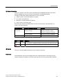
DANGER
indicates that death or severe personal injury will result if proper precautions are not taken.
WARNING
indicates that death or severe personal injury may result if proper precautions are not taken.
CAUTION
with a safety alert symbol, indicates that minor personal injury can result if proper precautions are not taken.
CAUTION
without a safety alert symbol, indicates that property damage can result if proper precautions are not taken.
NOTICE
indicates that an unintended result or situation can occur if the corresponding information is not taken into
account.
If more than one degree of danger is present, the warning notice representing the highest degree of danger will
be used. A notice warning of injury to persons with a safety alert symbol may also include a warning relating to
property damage.
Qualified Personnel
The product/system described in this documentation may be operated only by personnel qualified for the specific
task in accordance with the relevant documentation for the specific task, in particular its warning notices and
safety instructions. Qualified personnel are those who, based on their training and experience, are capable of
identifying risks and avoiding potential hazards when working with these products/systems.
Proper use of Siemens products
Note the following:
WARNING
Siemens products may only be used for the applications described in the catalog and in the relevant technical
documentation. If products and components from other manufacturers are used, these must be recommended
or approved by Siemens. Proper transport, storage, installation, assembly, commissioning, operation and
maintenance are required to ensure that the products operate safely and without any problems. The permissible
ambient conditions must be adhered to. The information in the relevant documentation must be observed.
Trademarks
All names identified by ® are registered trademarks of the Siemens AG. The remaining trademarks in this
publication may be trademarks whose use by third parties for their own purposes could violate the rights of the
owner.
Disclaimer of Liability
We have reviewed the contents of this publication to ensure consistency with the hardware and software
described. Since variance cannot be precluded entirely, we cannot guarantee full consistency. However, the
information in this publication is reviewed regularly and any necessary corrections are included in subsequent
editions.
Siemens AG
Industry Sector
Postfach 48 48
90026 NÜRNBERG
GERMANY
A5E02049034-02
Ⓟ 08/2010
Copyright © Siemens AG 2010.
Technical data subject to change
Preface
Purpose of the operating instructions
These operating instructions are intended to supplement the ET 200S Distributed I/O System
Operating Instructions. It contains a description of all the functions performed by the
IM 151-8 PN/DP CPU interface module. The operating instructions do not include functions
that relate generally to ET 200S. These can be found in the ET 200S Distributed I/O System
Operating Instructions.
The information contained in these operating instructions and the ET 200S Distributed I/O
System Operating Instructions allows you to commission ET 200S with the IM 151-8 PN/DP
CPU interface module and to run it as an IO controller on the PROFINET.
You will also find information on how the IM 151-8 PN/DP CPU interface module can be
operated together with the DP master module on the PROFIBUS DP.
Basic knowledge required
To understand these operating instructions you should have general experience in the field
of automation engineering.
Range of validity of these operating instructions
These Operating Instructions are valid for
● the IM 151-8 PN/DP CPU interface module (order number 6ES7151-8AB01-0AB0)
● the DP master module (order number 6ES7138-4HA00-0AB0)
● the components of the ET 200S distributed I/O system specified in the ET 200S
Distributed I/O System Operating Instructions.
Note
A description of the special features of the interface module IM151-8F PN/DP CPU can be
found in the product information on the Internet
(http://support.automation.siemens.com/WW/view/en/29713139).
These operating instructions contain a description of the components that was valid at the
time of publication. We reserve the right to issue a Product Information which contains up-todate information about new components and new versions of components.
IM 151-8 PN/DP CPU interface module
Operating Instructions, 06/2010, A5E02049034-02
3
Preface
Changes since the previous version
The following changes have been made compared with the previous version of these
Distributed I/O ET 200S, interface module IM151-8 PN/DP CPU operating instructions,
edition 06/2008, A5E02049033-01:
● PROFINET
– Support of isochronous real-time communication with "high performance"
– Support of isochronous mode on PROFINET
– Media redundancy
– can be configured as an I device
– Shared Device
– IP parameters are configurable via the DCP (Discovery and Configuration Protocol) or
SFB 104 "IP_CONF"
– Configuration and operation of I/O transfer areas in the case of operation as an I
device (direct access by a higher level IO controller to the local IM151-8 CPU I/O as
an I device)
– Initialized for PROFIenergy (SFB 73 / SFB 74)
– Keep Alive function supported
● Open communication via Industrial Ethernet
– Increased data lengths during open communication
– Several connections can be established for each port
– Using TCP/IP: several passive connections can be established for a port (multi-port)
– Extended system diagnostics of PROFINET interface:
Overview and detailed diagnostics of connections of "open communication via
Industrial Ethernet"
4
IM 151-8 PN/DP CPU interface module
Operating Instructions, 06/2010, A5E02049034-02
Preface
● Additional web server functionality
– Users can be configured for login
– Connections via http(s)
– Module state
– Display of the communication connections during open communication via Industrial
Ethernet (OUC)
– Extended connection diagnostics during open communication
– Display of resources during communication
– Display of the port statistics of IO devices
– Topology
– User pages (new SFC 99 required)
– Link to Web servers of other configured devices
– Status overview of all configured devices of the PROFINET IO system
– Automatic page update for all dynamic pages on the Web server
– Diagnostic buffer entries and messages can be downloaded as CSV file.
● Further functionalities
– Increased work memory
– Increased performance due to shorter instruction processing times
– Reading out service data
– Number of blocks that can be monitored using the status block increased from 1 to 2
– Effective from STEP 7 V5.5, increase in the status information that can be monitored
using the status block
– Number of breakpoints increased from 2 to 4
– Supports the status byte for power modules
– Encryption of blocks using S7 Block Privacy
– Local data stack size increased (32 kB per execution level/2 kB per block)
– Expansion of the block number range
– Time-delay interrupts: uniform OB 21 / OB 22
– Cyclic interrupts: uniform OB 32 - OB 35
– Number of displayed diagnostic buffer entries in CPU RUN mode is configurable
– Extension of the diagnostic buffer entries in the event of problems on the local I/O bus
of the IM151-8 PN/DP CPU
– Extension of the SFC 12 by 2 new modes for triggering the OB 86 when activating /
deactivating PROFIBUS slaves or PROFINET IO devices
IM 151-8 PN/DP CPU interface module
Operating Instructions, 06/2010, A5E02049034-02
5
Preface
Guide
The operating instructions contain the following guides which provide quick access to the
specific information you need:
● At the beginning of the documentation you will find a comprehensive table of contents.
● Important terms are explained in the glossary.
● Navigate to the most important topics in our documents using the index.
Recycling and disposal
The IM 151-8 PN/DP CPU interface module is recyclable due to its non-toxic materials. For
environmentally compliant recycling and disposal of your electronic waste, please contact a
company certified for the disposal of electronic waste.
Further support
If you have any questions relating to the products described in these operating instructions,
and do not find the answers in this document, please contact your Siemens partner at our
local offices.
You will find information on who to contact on the Web
(http://www.siemens.com/automation/partner).
A guide to the technical documentation for the various SIMATIC products and systems is
available in the Internet (http://www.siemens.com/automation/simatic/portal).
The online catalog and ordering systems are available on the Internet
(http://www.siemens.com/automation/mall).
Training center
We offer courses to help you get started with the ET 200S and the SIMATIC S7 automation
system. Please contact your regional training center or the central training center in
D -90327, Nuremberg, Germany.
You will find more information on the Web (http://www.siemens.com/sitrain).
6
IM 151-8 PN/DP CPU interface module
Operating Instructions, 06/2010, A5E02049034-02
Preface
Service & Support on the Internet
In addition to our documentation, we offer a comprehensive knowledge base on the Internet
(http://www.siemens.com/automation/service&support).
There you will find:
● Our Newsletter, which constantly provides you with the latest information about your
products.
● The right documentation for you using our Service & Support search engine.
● The bulletin board, a worldwide knowledge exchange for users and experts.
● Your local contact for Automation & Drives in our contact database.
● Information about on-site service, repairs, spare parts, and much more is available under
"Repairs, spare parts, and consulting".
See also
Support (http://support.automation.siemens.com/WW/view/en/11669702/133300)
IM 151-8 PN/DP CPU interface module
Operating Instructions, 06/2010, A5E02049034-02
7
Preface
8
IM 151-8 PN/DP CPU interface module
Operating Instructions, 06/2010, A5E02049034-02
Table of contents
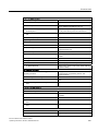
Preface ...................................................................................................................................................... 3
1
2
3
Description............................................................................................................................................... 15
1.1
Function of the IM 151-8 PN/DP CPU interface module .............................................................15
1.2
Properties of the IM 151-8 PN/DP CPU interface module...........................................................16
1.3
Properties of the DP master module............................................................................................19
1.4
Example configurations................................................................................................................20
Operating and display elements .............................................................................................................. 23
2.1
Operating and display elements of the IM 151-8 PN/DP CPU interface module ........................23
2.2
Status and error displays of the IM 151-8 PN/DP CPU interface module ...................................25
2.3
Display elements of the DP master module.................................................................................26
Communication........................................................................................................................................ 27
3.1
3.1.1
3.1.2
Interfaces .....................................................................................................................................27
PROFINET (PN)...........................................................................................................................27
PROFIBUS DP.............................................................................................................................32
3.2
3.2.1
3.2.2
3.2.3
3.2.4
3.2.5
3.2.6
3.2.7
Communication services..............................................................................................................33
Overview of communication services ..........................................................................................33
PG communication.......................................................................................................................35
OP communication.......................................................................................................................36
S7 communication .......................................................................................................................36
Routing.........................................................................................................................................37
Data set routing............................................................................................................................38
Data consistency..........................................................................................................................40
3.3
SNMP communication service .....................................................................................................40
3.4
Open communication via Industrial Ethernet ...............................................................................41
3.5
3.5.1
3.5.2
3.5.3
3.5.4
S7 connections ............................................................................................................................44
S7 connection as communication path ........................................................................................44
Assignment of S7 connections.....................................................................................................45
Distribution and availability of S7 connection resources .............................................................47
Connection resources for routing.................................................................................................48
3.6
DPV1............................................................................................................................................49
3.7
3.7.1
3.7.2
3.7.3
.....................................................................................................................................................51
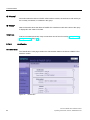
Language settings........................................................................................................................54
Settings in HW Config, "Web" tab................................................................................................56
Updating and saving information .................................................................................................59
IM 151-8 PN/DP CPU interface module
Operating Instructions, 06/2010, A5E02049034-02
9
Table of contents
3.7.4
3.7.4.1
3.7.4.2
3.7.4.3
3.7.4.4
3.7.4.5
3.7.4.6
3.7.4.7
3.7.4.8
3.7.4.9
3.7.4.10
4
5
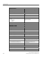
PROFINET .............................................................................................................................................. 95
4.1
4.1.1
4.1.2
4.1.3
4.1.4
Communication by means of PROFINET ................................................................................... 95
Introduction ................................................................................................................................. 95
PROFINET IO and PROFINET CBA .......................................................................................... 96
PROFINET IO System ................................................................................................................ 98
Blocks for PROFINET IO .......................................................................................................... 100
4.2
Isochronous real time communication ...................................................................................... 103
4.3
Prioritized startup ...................................................................................................................... 103
4.4
Device replacement without removable media / PD ................................................................. 104
4.5
IO devices that can be switched during operation .................................................................... 105
4.6
Isochronous mode..................................................................................................................... 105
4.7
I-Device ..................................................................................................................................... 106
4.8
Shared Device........................................................................................................................... 107
4.9
Media redundancy..................................................................................................................... 108
Memory concept .................................................................................................................................... 109
5.1
5.1.1
5.1.2
5.1.3
5.1.4
5.1.5
Memory areas and retentive memory ....................................................................................... 109
Memory areas of the IM 151-8 PN/DP CPU interface module ................................................. 109
Retentivity of load memory, system memory and RAM............................................................ 110
Retentivity of memory objects ................................................................................................... 111
Address areas of system memory ............................................................................................ 113
Properties of the SIMATIC Micro Memory Card ....................................................................... 116
5.2
5.2.1
5.2.2
Memory functions...................................................................................................................... 117
General: Memory functions ....................................................................................................... 117
Downloading user programs via SIMATIC Micro Memory Card to the IM 151-8 PN/DP
CPU interface module ............................................................................................................... 118
Handling blocks......................................................................................................................... 119
Encryption of blocks .................................................................................................................. 119
Download of new blocks or delta downloads ............................................................................ 120
Uploading blocks....................................................................................................................... 120
Deleting blocks.......................................................................................................................... 121
Compressing blocks.................................................................................................................. 121
Promming (RAM to ROM) ......................................................................................................... 121
CPU memory reset and restart ................................................................................................. 121
Recipes ..................................................................................................................................... 122
Measured value log files ........................................................................................................... 124
Backup of project data to SIMATIC Micro Memory Card.......................................................... 126
5.2.3
5.2.3.1
5.2.3.2
5.2.3.3
5.2.3.4
5.2.3.5
5.2.3.6
5.2.4
5.2.5
5.2.6
5.2.7
10
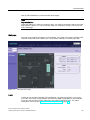
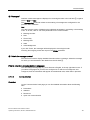
Web pages .................................................................................................................................. 60
Start page with general CPU information.................................................................................... 60
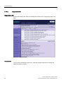
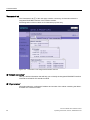
Identification ................................................................................................................................ 62
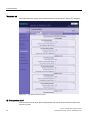
Diagnostic buffer ......................................................................................................................... 64
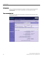
Module state................................................................................................................................ 66
Messages .................................................................................................................................... 72
Communication ........................................................................................................................... 73
Topology...................................................................................................................................... 80
Variable status ............................................................................................................................ 87
Variable tables ............................................................................................................................ 88
User pages .................................................................................................................................. 91
IM 151-8 PN/DP CPU interface module
Operating Instructions, 06/2010, A5E02049034-02
Table of contents
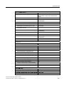
6
Mounting and connecting....................................................................................................................... 127
6.1
Content.......................................................................................................................................127
6.2
Installing the IM 151-8 PN/DP CPU interface module ...............................................................127
6.3
Connecting the IM 151-8 PN/DP CPU interface module ...........................................................128
6.4
Installing and connecting the DP master module ......................................................................131
7
Addressing............................................................................................................................................. 133
7.1
Addressing the I/O modules.......................................................................................................133
7.1.1
Slot-oriented addressing of the centralized I/O modules...........................................................133
7.1.2
User-oriented addressing of the I/O Modules ............................................................................136
8
7.2
Addressing on PROFIBUS DP...................................................................................................137
7.3
7.3.1
7.3.2
Addressing PROFINET IO .........................................................................................................138
Addressing on PROFINET IO ....................................................................................................138
Assignment of the IP address parameters and device name ....................................................139
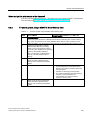
Commissioning ...................................................................................................................................... 143
8.1
Overview ....................................................................................................................................143
8.2
Commissioning procedure .........................................................................................................143
8.2.1
Procedure: Commissioning the hardware..................................................................................143
8.2.2
Procedure: Software commissioning .........................................................................................145
8.3
Commissioning check list...........................................................................................................147
8.4
8.4.1
8.4.2
8.4.3
8.4.4
8.4.5
8.4.6
Commissioning the modules......................................................................................................148
Inserting/Replacing a SIMATIC Micro Memory Card.................................................................148
Initial power on ...........................................................................................................................150
Reset the IM 151-8 PN/DP CPU interface module using the mode selector switch .................151
Formatting the SIMATIC Micro Memory Card ...........................................................................155
Resetting to the as-delivered state ............................................................................................156
Connecting a programming device / PC to the integrated PROFINET interface of the IM
151-8 PN/DP CPU interface module .........................................................................................158
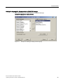
Starting SIMATIC Manager........................................................................................................160
Monitoring and modifying I/Os ...................................................................................................161
8.4.7
8.4.8
8.5.3
Commissioning PROFIBUS DP .................................................................................................165
Commissioning the PROFIBUS DP network .............................................................................165
Commissioning the IM 151-8 PN/DP CPU interface module with DP master module as a
DP master ..................................................................................................................................166
Direct data exchange .................................................................................................................170
8.6
8.6.1
8.6.2
Commissioning PROFINET IO ..................................................................................................172
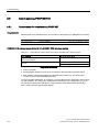
Requirements for commissioning PROFINET ...........................................................................172
Configuring and commissioning the PROFINET IO system ......................................................173
8.5
8.5.1
8.5.2
9
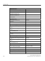
Service and maintenance ...................................................................................................................... 181
9.1
Overview ....................................................................................................................................181
9.2
Backing up firmware on a SIMATIC Micro Memory Card..........................................................181
9.3
Updating the firmware................................................................................................................182
9.3.1
When should you update the IM 151-8 PN/DP CPU interface module? ...................................182
9.3.2
Firmware update using a SIMATIC Micro Memory Card ...........................................................183
9.3.3
Updating the firmware online (via networks)..............................................................................185
9.4
Backing up project data on a SIMATIC Micro Memory Card.....................................................186
9.5
Replacing the IM 151-8 PN/DP CPU interface module .............................................................188
9.6
Replacing the DP master module ..............................................................................................190
IM 151-8 PN/DP CPU interface module
Operating Instructions, 06/2010, A5E02049034-02
11
Table of contents
10
11
12
12
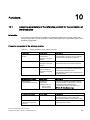
Functions ............................................................................................................................................... 193
10.1
Assigning parameters of the reference junction for the connection of thermocouples ............. 193
10.2
10.2.1
10.2.2
10.2.3
Removal and insertion of modules during operation ................................................................ 195
Overview ................................................................................................................................... 195
What happens when modules are removed during operation .................................................. 196
Procedure when modules are inserted during operation .......................................................... 196
10.3
Switching power modules off and on during operation ............................................................. 198
10.4
Power module with status byte ................................................................................................. 199
Debugging functions, diagnostics and troubleshooting .......................................................................... 201
11.1
Overview ................................................................................................................................... 201
11.2
Reading/saving service data ..................................................................................................... 201
11.3
Identification and maintenance data of the IM 151-8 PN/DP CPU interface module ............... 202
11.4
11.4.1
11.4.2
11.4.3
11.4.4
Debugging functions ................................................................................................................. 204
Overview: Debugging functions ................................................................................................ 204
Overview: Diagnostics............................................................................................................... 207
Diagnostic functions available in STEP 7 ................................................................................. 210
Network infrastructure diagnostics (SNMP) .............................................................................. 211
11.5
11.5.1
11.5.2
11.5.3
11.5.4
11.5.5
11.5.6
11.5.7
Diagnostics using status and error LEDs.................................................................................. 213
Introduction ............................................................................................................................... 213
Status and error displays of the IM 151-8 PN/DP CPU interface module ................................ 213
Evaluating the SF LED in case of software errors .................................................................... 215
Evaluating the SF LED in case of hardware errors................................................................... 217
Status and error displays for the PN interface .......................................................................... 219
Status and Error Indicators: PROFINET IO Devices ................................................................ 222
Status and error displays of the DP master module ................................................................. 223
11.6
11.6.1
Diagnostics on the PROFIBUS DP ........................................................................................... 224
Diagnostics of the IM 151-8 PN/DP CPU interface module as a DP master............................ 224
11.7
Defective configuration statuses of the ET 200S...................................................................... 227
11.8
Failure of the load voltage from the power module................................................................... 227
11.9
Basics of diagnostics in PROFINET IO..................................................................................... 228
Technical data ....................................................................................................................................... 229
12.1
General technical data .............................................................................................................. 229
12.2
12.2.1
12.2.2
IM 151-8 PN/DP CPU interface module.................................................................................... 229
IM 151-8 PN/DP CPU with DP master module block diagram ................................................. 229
IM 151-8 PN/DP CPU technical specifications ......................................................................... 230
12.3
12.3.1
DP master module .................................................................................................................... 242
Technical specifications - DP master module ........................................................................... 242
IM 151-8 PN/DP CPU interface module
Operating Instructions, 06/2010, A5E02049034-02
Table of contents
A
Appendix................................................................................................................................................ 243
A.1
A.1.1
A.1.2
Order numbers ...........................................................................................................................243
Module order numbers...............................................................................................................243
Order numbers of accessories...................................................................................................244
A.2
A.2.1
A.2.2
Dimension drawings...................................................................................................................245
IM 151-8 PN/DP CPU interface module ....................................................................................245
DP master module .....................................................................................................................246
A.3
A.3.1
A.3.2
A.3.2.1
A.3.2.2
A.3.2.3
A.3.2.4
A.3.3
A.3.3.1
A.3.3.2
A.3.3.3
A.3.4
A.3.4.1
A.3.4.2
Cycle and response times..........................................................................................................246
Overview ....................................................................................................................................246
Cycle time ..................................................................................................................................247
Overview: Cycle time .................................................................................................................247
Calculating the cycle time ..........................................................................................................250
Communication load ..................................................................................................................252
Cycle time extension as a result of testing and commissioning functions.................................254
Response time ...........................................................................................................................255
Overview: Response time ..........................................................................................................255
Shortest response time ..............................................................................................................257
Longest response time...............................................................................................................258
Interrupt response time ..............................................................................................................259
Overview: Interrupt response time .............................................................................................259
Reproducibility of Time-Delay and Watchdog Interrupts ...........................................................260
A.4
Additional documentation...........................................................................................................261
Glossary ................................................................................................................................................ 263
Index...................................................................................................................................................... 295
IM 151-8 PN/DP CPU interface module
Operating Instructions, 06/2010, A5E02049034-02
13
Table of contents
14
IM 151-8 PN/DP CPU interface module
Operating Instructions, 06/2010, A5E02049034-02
1
Description
1.1
Function of the IM 151-8 PN/DP CPU interface module
The IM 151-8 PN/DP CPU interface module is a component of the ET 200S distributed I/O
system with degree of protection IP20. The IM 151-8 PN/DP CPU interface module is an
"intelligent preprocessor". It enables you to decentralize control tasks.
Therefore, an ET 200S with IM 151-8 PN/DP CPU can exercise full and, if necessary,
independent control over a process-related functional unit.
● Functions of the IM151-8 PN/DP CPU on PROFINET:
– IO controller
– I-Device
– I device and IO controller
– PROFINET CBA device with or without proxy functionality for PROFIBUS DP (for
proxy functionality for PROFIBUS DP, the DP master module must additionally be
plugged in)
● Functions of the IM151-8 PN/DP CPU on PROFIBUS DP:
– DP master together with the optional DP master module
The use of the IM 151-8 PN/DP CPU interface module leads to further modularization and
standardization of process-related functional units and simple, clear machine concepts.
IM 151-8 PN/DP CPU interface module
Operating Instructions, 06/2010, A5E02049034-02
15
Description
1.2 Properties of the IM 151-8 PN/DP CPU interface module
1.2
Properties of the IM 151-8 PN/DP CPU interface module
Properties of the IM 151-8 PN/DP CPU interface module
The IM 151-8 PN/DP CPU interface module has the following special features:
● The interface module has PLC functionality (integrated CPU component with 192 kB work
memory).
● The interface module can only be used with the load memory inserted (SIMATIC Micro
Memory Card).
● The interface module can be enhanced with up to 63 I/O modules from the ET 200S
range.
● The maximum bus length is 2 m.
● Connection to PROFINET via a PROFINET interface with integrated switch and 3 RJ45
ports.
– The IP address for PROFINET can be saved, for example, on the SIMATIC Micro
Memory Card during the hardware configuration but can also be assigned by the user
program (SFB 104) or assigned externally via DCP (for instance, using the Setup Tool
or even by a higher level IO controller).
– Ports 1 and 2 can also be used as ring ports for the creation of redundant ring
structures on the Ethernet (media redundancy)
– Communication is established via PROFINET, for which PROFINET IO is supported
as an IO controller (to which up to 128 IO devices can be connected) and / or and I
device or PROFINET CBA.
– The PROFINET interface allows both PD/OP communication and other types of
communication, such as open communication and S7 communication.
● As a PROFINET IO controller, the IM 151-8 PN/DP CPU interface module also supports
– the real-time communication via RT and IRT
– the prioritized start-ups of PROFINET IO devices
– the replacement of devices without exchangeable medium/PD
– the exchange of IO devices during operation (changing partner ports)
– Isochronous mode on PROFINET
– Shared Device.
● The IM151-8 PN/DP CPU interface module can also be used as an I device at the
PROFINET IO. It can then exchange data with a higher level controller and thus be used
as an intelligent pre-processing unit for subprocesses.
– An IM151-8 PN/DP interface module used as an I device can at the same time
function as an IO controller and thus power a lower level PROFINET IO subnet of its
own.
– An IM151-8 PN/DP interface module used as an I device can also be used as a
shared I device.
– When used as an I device, I/O transfer areas can be configured which allow a higher
level IO controller to access an IM151-8 PN/DP interface module directly via the local
I/O.
16
IM 151-8 PN/DP CPU interface module
Operating Instructions, 06/2010, A5E02049034-02
Description
1.2 Properties of the IM 151-8 PN/DP CPU interface module
● Down times are minimized thanks to the integrated diagnostics.
● It is possible to update the firmware via SIMATIC Micro Memory Card or online via the
network.
● An integrated web server for user-defined web pages, information, status and diagnostics
provides the respective data to any location.
● The interface module has a mode selector with positions for RUN, STOP and MRES.
● There are 10 LEDs on the front of the interface module to indicate the following:
– ET 200S faults (SF)
– bus faults on PROFINET (BF-PN)
– available maintenance information (MT)
– Supply voltage for electronic components (ON)
– Force requests (FRCE)
– operating mode of the IM 151-8 PN/DP CPU interface module (RUN and STOP)
– Connection status at ports 1 and 3 of the PROFINET interface (P1 - LINK, P2 - LINK,
P3 - LINK)
● The IM 151-8 PN/DP CPU interface module can be expanded by one DP master module.
This also lends it the functionality of a DP master.
Integration of the IM 151-8 PN/DP CPU interface module in ET 200S
The IM 151-8 PN/DP CPU interface module is integrated in ET 200S just like any other
module; i. e. same configuration concept, installation and expansion capability.
Information on this can be found in the ET 200S distributed I/O system Operating
Instructions.
How do I configure and program the ET 200S with IM 151-8 PN/DP CPU ?
To configure an ET 200S with IM 151-8 PN/DP CPU (configuration and parameter
assignment) and to program the IM 151-8 PN/DP CPU interface module you will need the
STEP 7 project design software, V5.5 or later.
The procedure for configuring the ET 200S with IM 151-8 PN/DP CPU is described in the
Commissioning (http://support.automation.siemens.com/WW/view/en/31977679) section of
these Operating Instructions. In the S7-300 Instruction List you will find the STEP 7
instruction set for programming the IM151-8 PN/DP CPU interface module. The instruction
list is available as a download from the Internet
(http://support.automation.siemens.com/WW/view/en/31977679).
IM 151-8 PN/DP CPU interface module
Operating Instructions, 06/2010, A5E02049034-02
17
Description
1.2 Properties of the IM 151-8 PN/DP CPU interface module
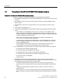
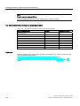
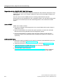
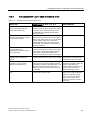
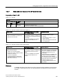
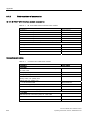
Constraints on using motor starters and ET 200S modules
With central use in an ET 200S with IM 151-8 PN/DP CPU the following motor starters and
ET 200S modules can cause disturbing responses. The product versions specified of these
motor starters and ET 200S modules should not be used in an ET 200S with IM
151-8 PN/DP CPU.
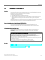
Table 1- 1
Constraints on using motor starters and ET 200S modules
Motor starter / module
Order number
Up to and
including product
version
DS1e-x direct-on-line starter; HF
3RK1301-0❑B10-❑AA2
E06
3RK1301-0❑B13-❑AA2
E06
3RK1301-0❑B❑0-❑AA3
E03
3RK1301-0❑B❑❑-❑AA4
E02
2AI I 2WIRE HS analog electronic module
6ES7134-4GB52-0AB0
E03
2 AI I 4WIRE HS analog electronic module
6ES7134-4GB62-0AB0
E01
Analog electronic module 2AI U HS
6ES7134-4FB52-0AB0
E01
2AO I HS analog electronic module
6ES7135-4GB52-0AB0
E01
2AO U HS analog electronic module
6ES7135-4FB52-0AB0
E03
RS1e-x reversing starters; HF
F-DS1e-x fail-safe direct starters; HF
F-RS1e-x fail-safe reversing starters; HF
DS1e-x direct-on-line starter; HF
RS1e-x reversing starters; HF
DSS1e-x direct soft starters; HF
DS1e-x direct-on-line starter; HF
RS1e-x reversing starters; HF
DSS1e-x direct soft starters; HF
F-DS1e-x fail-safe direct starters; HF
F-RS1e-x fail-safe reversing starters; HF
18
IM 151-8 PN/DP CPU interface module
Operating Instructions, 06/2010, A5E02049034-02
Description
1.3 Properties of the DP master module
1.3
Properties of the DP master module
Together with the DP master module you can operate the IM 151-8 PN/DP CPU interface
module as a DP master.
Note
The IM 151-8 PN/DP CPU interface module can be expanded by no more than one DP
master module.
Properties of the DP master module
The DP master module has the following special features:
● The PROFIBUS DP address is saved alongside the HW Config configuration on the
SIMATIC Micro Memory Card in the IM 151-8 PN/DP CPU interface module.
● There is 1 LED on the front of the DP master module to indicate bus faults on the
PROFIBUS DP (BF).
● Connection to PROFIBUS DP via the DP interface (RS 485) on the DP master module
Integration of the DP master module in ET 200S
The DP master module is connected to the IM 151-8 PN/DP CPU from the right and hence
integrated in the ET 200S.
How do I configure and program the ET 200S with IM 151-8 PN/DP CPU and master module?
To configure an ET 200S with IM 151-8 PN/DP CPU and DP master module (configuration
and parameter assignment) and to program the IM 151-8 PN/DP CPU interface module you
will need the STEP 7 project design software, V5.5 or later.
The procedure for configuring the ET 200S with IM 151-8 PN/DP CPU and DP master
module is described in the Commissioning (Page 172) section of these Operating
Instructions.
IM 151-8 PN/DP CPU interface module
Operating Instructions, 06/2010, A5E02049034-02
19
Description
1.4 Example configurations
1.4
Example configurations
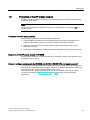
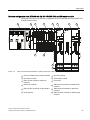
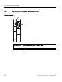
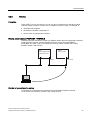
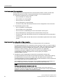
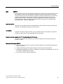
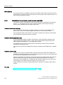
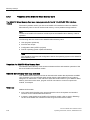
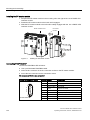
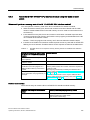
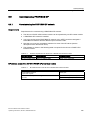
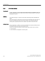
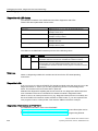
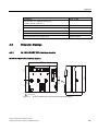
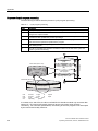
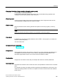
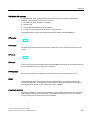
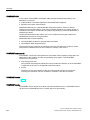
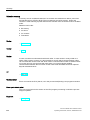
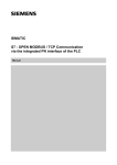
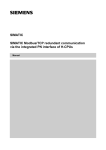
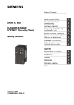
Example configuration of an ET 200S with IM 151-8 PN/DP CPU
The figure below shows an example configuration of an ET 200S with IM 151-8 PN/DP CPU.
Figure 1-1
View of the ET 200S distributed I/O system with IM 151-8 PN/DP CPU
① IM 151-8 PN/DP CPU interface module ④ Terminating module
② PM-E power module for electronic
⑤ TM-E terminal modules for electronic
modules
③ Electronic modules
20
modules
⑥ TM-P terminal modules for PM-E power
modules
IM 151-8 PN/DP CPU interface module
Operating Instructions, 06/2010, A5E02049034-02
Description
1.4 Example configurations
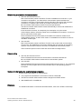
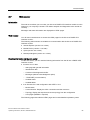
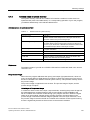
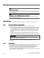
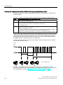
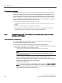
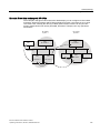
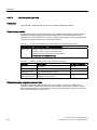
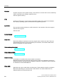
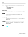
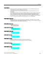
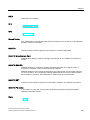
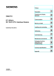
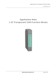
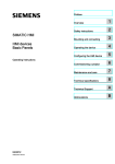
Example configuration of an ET 200S with IM 151-8 PN/DP CPU and DP master module
The figure below shows an example configuration of an ET 200S with IM 151-8 PN/DP CPU
and DP master module.
Figure 1-2
View of the ET 200S distributed I/O system with IM 151-8 PN/DP CPU and DP master module
① IM 151-8 PN/DP CPU interface module ⑦ Reversing starter
② DP master module
⑧ Terminating module
③ PM-E power module for electronic
⑨ Power bus
modules
④ Electronic modules
⑩ TM-P terminal module for PM-D power
⑤ PM-D power module for motor starters
⑪ TM-E terminal modules for electronic
⑥ Direct starters
⑫ TM-P terminal modules for PM-E power
IM 151-8 PN/DP CPU interface module
Operating Instructions, 06/2010, A5E02049034-02
modules
modules
modules
21
Description
1.4 Example configurations
22
IM 151-8 PN/DP CPU interface module
Operating Instructions, 06/2010, A5E02049034-02
2
Operating and display elements
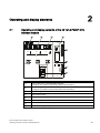
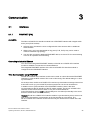
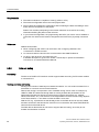
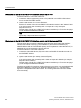
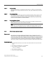
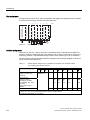
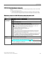
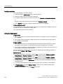
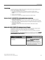
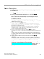
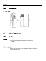
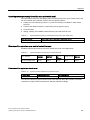
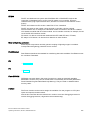
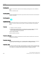
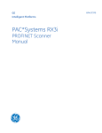
2.1
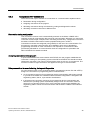
Operating and display elements of the IM 151-8 PN/DP CPU
interface module
,0
31'3&38
6)
%)31
07
21
35
35
3
)5&(
581
;
352),1(7
/$1
6723
3 3 3
/,1.
;
(76
'&9
/
0
;
/
0
(6$%$%
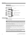
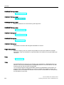
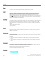
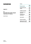
Number
Designation
①
RJ45 socket (port 1 of the PROFINET interface)
R: Ring port for creation of ring topology with media redundancy
②
RJ45 socket (port 2 of the PROFINET interface)
R: Ring port for creation of ring topology with media redundancy
③
RJ45 socket (port 3 of the PROFINET interface)
④
Mode selector switch
⑤
Status and error displays of the IM 151-8 PN/DP CPU interface module
⑥
Status displays of the PROFINET interface
⑦
Slot for the SIMATIC Micro Memory Card
⑧
Connection for supply voltage
IM 151-8 PN/DP CPU interface module
Operating Instructions, 06/2010, A5E02049034-02
23
Operating and display elements
2.1 Operating and display elements of the IM 151-8 PN/DP CPU interface module
Slot for the SIMATIC Micro Memory Card
Memory module is a SIMATIC Micro Memory Card. You can use MMCs as load memory and
as portable storage media. The slot for the SIMATIC Micro Memory Card can be accessed
from the front of the interface module. The Inserting/Replacing a Micro Memory Card section
contains detailed information on inserting the SIMATIC Micro Memory Card.
Note
The IM151-8 PN/DP CPU interface module does not have an integrated load memory, so
you will need to connect a SIMATIC Micro Memory Card to the IM 151-8 PN/DP interface
module in order to use it.
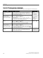
Mode selector switch
You can use the mode selector switch to set the current operating mode of the
IM 151-8 PN/DP CPU .
Table 2- 1
Mode selector switch settings
Position
Meaning
Description
RUN
RUN mode
The IM 151-8 PN/DP CPU interface module processes the user
program.
STOP
STOP mode
The IM 151-8 PN/DP CPU interface module does not process the
user program.
MRES
Memory reset
Mode selector switch setting for
Memory reset of the IM 151-8 PN/DP CPU interface module
Backing up the firmware to the SIMATIC Micro Memory Card
Resetting to the as-supplied state
A memory reset using the mode selector requires a number of
steps to be carried out in a set order.
Reference
● Operating modes of the IM 151-8 PN/DP CPU interface module: STEP 7 Online Help.
● Information on performing a memory reset of the IM 151-8 PN/DP CPU interface module:
Section Resetting the IM 151-8 PN/DP CPU interface module using the mode selector
switch)
● Evaluation of the LEDs for errors or diagnostics: See the Diagnostics using status and
error LEDs section.
See also
Inserting/Replacing a SIMATIC Micro Memory Card (Page 148)
24
IM 151-8 PN/DP CPU interface module
Operating Instructions, 06/2010, A5E02049034-02
Operating and display elements
2.2 Status and error displays of the IM 151-8 PN/DP CPU interface module
2.2
Status and error displays of the IM 151-8 PN/DP CPU interface
module
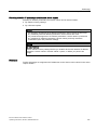
General status and error displays
Table 2- 2
General status and error displays of the IM 151-8 PN/DP CPU interface module
LED designation
Color
Meaning
SF
Red
Group fault for hardware or software error
MT
Yellow
Maintenance information
ON
Green
Supply voltage for the IM 151-8 PN/DP CPU
FRCE
Yellow
LED is lit: Active force job
RUN
Green
LED flashes at 2 Hz: Node flash test function.
IM 151-8 PN/DP CPU in RUN
The LED flashes during STARTUP at a rate of 2 Hz, and in HOLD
state at 0.5 Hz.
STOP
Yellow
IM 151-8 PN/DP CPU in STOP or in HOLD or STARTUP
The LED flashes at 0.5 Hz when the CPU requests a memory reset,
and during the reset at 2 Hz.
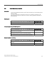
Status and error displays for the bus interfaces
Table 2- 3
Status and error displays for the bus interfaces of the IM 151-8 PN/DP CPU interface
module
LED designation
Color
Meaning
BF-PN
Red
Bus fault on the PROFINET
P1 - LINK
Green
Connection at port 1 is active
P2 - LINK
Green
Connection at port 2 is active
P3 - LINK
Green
Connection at port 3 is active
Reference
● Operating modes of the IM 151-8 PN/DP CPU interface module: STEP 7 Online Help
● Information on performing a memory reset of the IM 151-8 PN/DP CPU interface module:
Section Resetting the IM 151-8 PN/DP CPU interface module using the mode selector
switch)
● Evaluation of the LEDs for errors or diagnostics: See the Diagnostics using status and
error LEDs section
IM 151-8 PN/DP CPU interface module
Operating Instructions, 06/2010, A5E02049034-02
25
Operating and display elements
2.3 Display elements of the DP master module
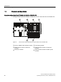
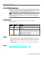
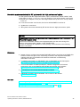
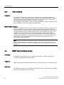
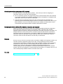
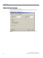
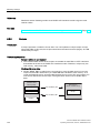
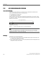
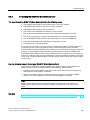
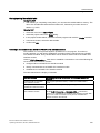
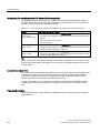
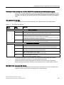
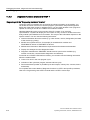
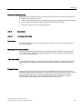
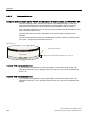
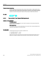
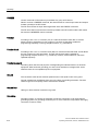
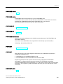
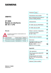
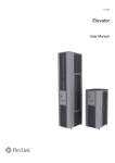
2.3
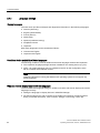
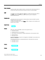
Display elements of the DP master module
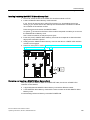
Display elements
'3
0DVWHU
%)
;
352),%86'3
(6
+$
$%
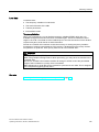
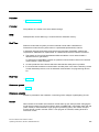
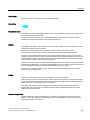
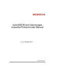
Figure 2-1
26
Display elements of the DP master module
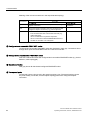
The figure shows ...
the following elements of the DP master module
①
Status and error displays
②
9-pin sub D socket for PROFIBUS DP
IM 151-8 PN/DP CPU interface module
Operating Instructions, 06/2010, A5E02049034-02
Communication
3.1
Interfaces
3.1.1
PROFINET (PN)
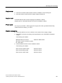
3
Availability
The IM151-8 PN/DP CPU interface module has a PROFINET interface with integral switch
and 3 ports (RJ45 sockets).
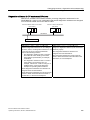
● At these ports, the network can be configured with a line structure with no additional
external switch.
● When ports 1 and 2 are designated as ring ports (P1 R, P2 R), they can be used to
create a redundant ring topology.
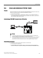
● You can also connect an additional PROFINET device, such as a PD for commissioning
or an OP for operation and monitoring.
Connecting to Industrial Ethernet
You can use the integrated PROFINET interface of the IM 151-8 PN/DP CPU interface
module to establish a connection to Industrial Ethernet.
The integrated PROFINET interface of the IM 151-8 PN/DP CPU interface module is
configured via the PROFINET interface.
Time Synchronization using PROFINET
The IM 151-8 PN/DP CPU interface module can be used as a time client at the PROFINET
interface by using the NTP method. This is set in HW Config. The default setting is no time
synchronization.
As the time client, the IM 151-8 PN/DP CPU receives synchronization message frames from
a time NTP server (e.g. SICLOCK TS) and accepts this time as its own internal time.
In addition to time synchronization at the PROFINET interface, there is also time
synchronization at the DP interface of the DP master module. The IM 151-8 PN/DP CPU
interface module can be the time slave on only one of these interfaces.
At the PN interface, there is only the functionality as a time client (functionality is the same
as that of a time slave at the DP interface).
Example:The IM 151-8 PN/DP CPU interface module is synchronized by a time server over
NTP via the PN interface (corresponding to the functionality as a time slave). The
IM 151-8 PN/DP CPU interface module can then only be used as a time master at the DP
interface.
IM 151-8 PN/DP CPU interface module
Operating Instructions, 06/2010, A5E02049034-02
27
Communication
3.1 Interfaces
Devices capable of PROFINET (PN) communication
● PROFINET IO controller
● PROFINET IO devices (for example, interface module IM 151-3 PN in an ET 200S)
● PROFINET CBA components
● S7-300 / S7-400 with PROFINET interface (for example, CPU 317-2 PN/DP or CP 343-1)
● Active network components (a switch, for example)
● IE/PB link
● Programming device / PC with network card
Properties of the PROFINET interface
Properties
IEEE standard
802.3
Connector design
Ports 1 to 3
RJ45
Transmission speed
Up to 100 Mbps
Media
Twisted pair Cat5 (100 BASE-TX)
Media redundancy
to IEC 61158
Note
Networking PROFINET components
The use of switches, rather than hubs, for networking PROFINET components brings about
a substantial improvement in decoupling bus traffic, and improves runtime performance
under higher bus load. PROFINET CBA with cyclic PROFINET interconnections requires the
use of switches in order to maintain compliance with performance specifications. Full duplex
mode at 100 Mbps is mandatory for cyclic PROFINET interconnections.
PROFINET IO also requires the use of switches and 100 Mbps full duplex mode.
For PROFINET IO in IRT mode (Isochronous Real Time) all PROFINET devices in the sync
domain must be IRT-capable, even the switches.
28
IM 151-8 PN/DP CPU interface module
Operating Instructions, 06/2010, A5E02049034-02
Communication
3.1 Interfaces
Configuring the port properties of the PROFINET interface in STEP 7
The PROFINET interfaces in our devices are preset to a default "automatic setting"
(Autonegotiation). Ensure that all devices connected to the PROFINET interface of the IM
151-8 PN/DP CPU interface module are also set to the "Autonegotiation" operating mode.
This is the default setting of standard PROFINET / Ethernet components.
If you connect a device to the PROFINET interface of the IM 151-8 PN/DP CPU interface
module that does not support the "automatic setting" (Autonegotiation) operating mode, or if
you select a setting other than the "automatic setting" (Autonegotiation), note the following:
● PROFINET IO and PROFINET CBA require operation with 100 Mbps full-duplex, i.e.
when the PROFINET interface of the IM 151-8 PN/DP CPU interface module for
PROFINET IO / CBA communication and Ethernet communication is used at the same
time, the PROFINET interface can only be operated with 100 Mbps full-duplex.
● If the PROFINET interface of the IM 151-8 PN/DP CPU interface module is used only for
Ethernet communication, alongside the "automatic setting" (Autonegotiation) 100 Mbps
full-duplex or 10 Mbps full-duplex operating modes can be used. Half-duplex mode is not
allowed in any situation.
Reason: If, for example, a switch permanently set to "10 Mbps half-duplex" is connected to
the PROFINET interface of the IM 151-8 PN/DP CPU interface module, due to the
"Autonegotiation" setting the IM 151-8 PN/DP CPU interface module forwards this setting to
the partner device - i.e. the communication operates de facto with "10 Mbps half-duplex".
However, since PROFINET IO and PROFINET CBA require operation with 100 Mbps fullduplex, this operating mode is not allowed.
Note
To configure the ports of IO devices which are to perform a prioritized start-up refer to the
special information under PROFINET System Description.
Disabling a port of the PROFINET interface with IM 151-8 PN/DP CPU
In STEP 7 HW Config you can disable a port of the PROFINET interface of an IM
151-8 PN/DP CPU interface module. This is enabled as default.
The IM 151-8 PN/DP CPU interface module cannot be reached via a disabled port in the
PROFINET interface.
Note that it is not possible to perform communication functions, like for example, PD / OP
functions, open IE communications or S7 communication, via a disabled port.
Note
In the case of an IM 151-8 PN/DP CPU interface module one port must always be enabled
so that access to the module is always guaranteed.
IM 151-8 PN/DP CPU interface module
Operating Instructions, 06/2010, A5E02049034-02
29
Communication
3.1 Interfaces
Addressing the ports
To diagnose the individual ports of a PROFINET interface, these ports must each have a
separate diagnostics address. The addressing is done in HW Config.
For further information, refer to the PROFINET System Description.
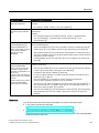
The diagnostic message (fault and maintenance information) can be enabled using OB 82
(enable in HW Config) and then analyzed using SFB 54, for example, in order to diagnose
any problems identified in the user program. There are also various data records (read using
SFB 52) and system status lists (read using SFC 51) provided for more detailed diagnostics.
Diagnostics is also possible in STEP 7 (e.g. communication diagnostics, network connection,
Ethernet statistics, IP parameters).
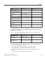
Send clock and send cycle
Controllers and devices with a standardized send clock can be used in a PROFINET IO
subnet. For devices that do not support a faster controller send clock, the send clock is
adapted to the capabilities of the device. That is, you could operate devices both at a send
clock of 250 µs and 1 ms on a IM151-8 PN/DP CPU interface module (IO controller) which
operates at a send clock of 250 µs.
The device send cycle can be set within a relatively large range. This, in turn, depends on
the send clock. The following update times can be configured when using the
IM151-8 PN/DP CPU interface module:
Real-time communication
Send clock
For RT:
250 µs
⇒
250 µs to 128 ms
500 µs
⇒
500 µs to 256 ms
1 ms
⇒
1 ms to 512 ms
2 ms
⇒
2 ms to 512 ms
4 ms
⇒
4 ms to 512 ms
250 µs
⇒
250 µs to 128 ms
500 µs
⇒
500 µs to 256 ms
1 ms
⇒
1 ms to 512 ms
250 µs
⇒
250 µs to 4 ms
500 µs
⇒
500 µs to 8 ms
1 ms
⇒
1 ms to 16 ms
2 ms
⇒
2 ms to 32 ms
4 ms
⇒
4 ms to 64 ms
For IRT with the "high
flexibility" option:
For IRT with the "high
performance" option:
Update Time
The minimum send cycle depends on the number of devices in use, the amount of
configured user data and the communication portion for PROFINET IO. STEP 7
automatically considers these dependencies during configuration.
30
IM 151-8 PN/DP CPU interface module
Operating Instructions, 06/2010, A5E02049034-02
Communication
3.1 Interfaces
Non-whole number send clocks for IRT systems with the "high performance" option:
For IRT systems with the "High Performance" option, as well as the "whole number" send
clocks (250 µs, 500 µs, 1 ms, 2 ms, 4 ms), any number of "non-whole number" send clocks
can be set up in multiples of 125 µs in the range between 250 µs and 4 ms: 375 µs, 625 µs
… 3.875 ms.
For "non-whole number" send clocks, the rule for all PROFINET IO devices is:
● Update time = send clock
● IRT systems cannot be extended by RT devices into the "High performance" option
NOTICE
Communication shutdown during memory reset / firmware updates / after POWER OFF on
CPUs with integrated switch
Note that the PROFINET interface and integrated switch are shut down during CPU
memory reset and firmware updates, or after POWER OFF.
If a CPU is configured for operation in a line topology, communication to the following
devices is shut down.
Reference
● Details of how to configure the integral PROFINET interface of the IM 151-8 PN/DP CPU
interface module are given in the Connecting a PD/PC to the integrated PROFINET
interface of the IM 151-8 PN/DP CPU interface module and Commissioning
PROFINET IO sections.
● For additional information on PROFINET, refer to PROFINET System Description
(http://support.automation.siemens.com/WW/view/en/19292127).
● For more information on Ethernet networks, network configuration and network
components, refer to the SIMATIC NET twisted pair and fiber optic networks
(http://support.automation.siemens.com/WW/view/en/8763736) manual:
● Commissioning Component Based Automation Systems
(http://support.automation.siemens.com/WW/view/en/18403908)
● Additional information about PROFINET can be found on the Internet
(http://www.profinet.com).
See also
Connecting a programming device / PC to the integrated PROFINET interface of the IM
151-8 PN/DP CPU interface module (Page 158)
Configuring and commissioning the PROFINET IO system (Page 173)
IM 151-8 PN/DP CPU interface module
Operating Instructions, 06/2010, A5E02049034-02
31
Communication
3.1 Interfaces
3.1.2
Availability
Properties
PROFIBUS DP
Together with the optional DP master module, the IM 151-8 PN/DP CPU interface module
has an RS 485 interface with DP master functionality.
The PROFIBUS DP interface on the DP master module is mainly used to connect distributed
I/O. PROFIBUS DP allows you to create large subnets, for example.
You can configure the PROFIBUS DP interface as master or to be inactive. It allows a
transmission rate of up to 12 Mbps.
The IM 151-8 PN/DP CPU broadcasts its bus parameters (such as the baud rate) to the
PROFIBUS DP interface when it is used as the master. A programming device, for example,
can thus receive the correct parameters and automatically connect to a PROFIBUS subnet.
In your configuration you can specify to disable bus parameter broadcasting.
Time synchronization using PROFIBUS
Time synchronization is possible via the DP interface on the DP master module of the IM
151-8 PN/DP CPU interface module. The IM 151-8 PN/DP CPU may act as the time master
(with suitably programmed synchronization interval) or time slave. This is set in HW Config.
The default setting is no time synchronization.
As the time master, the IM 151-8 PN/DP CPU interface module sends synchronization
message frames to the DP interface at the configured synchronization interval in order to
synchronize other stations on the connected PROFIBUS DP subnet.
If the IM151-8 PN/DP CPU interface module is configured on the DP interface as time
master, then there will be no time synchronization of the connection time slaves, as the clock
of the IM 151-8 PN/DP CPU interface module is still set to default.
Note that the clock of the IM151-8 PN/DP CPU interface module is not yet set when it ships,
after a reset to factory setting by means of the mode selector switch or after a firmware
update.
As soon as the time of day is set the first time, the time synchronization starts as the time
master by means of:
● PD function
● SFC call or
● a different time master (if the IM 151-8 PN/DP CPU interface module has also be
configured as a time client by the PROFINET interface).
As the time slave, the IM 151-8 PN/DP CPU interface module receives synchronization
message frames from a different time master and accepts this time as its own internal time.
In addition to time synchronization at the DP interface of the DP master module, there is also
time synchronization at the PROFINET interface. The IM 151-8 PN/DP CPU interface
module can be the time slave on only one of these interfaces. At the PN interface, it can only
act as a time client (functionality is the same as that of a time slave at the DP interface).
Example: The IM 151-8 PN/DP CPU interface module is time synchronized by a time server
over NTP via the PN interface. The IM 151-8 PN/DP CPU interface module can then only be
used as a time master at the DP interface.
32
IM 151-8 PN/DP CPU interface module
Operating Instructions, 06/2010, A5E02049034-02
Communication
3.2 Communication services
Devices capable of PROFIBUS DP communication
● Programming device / PC
● OP/TP
● DP slaves
● Actuators/Sensors
● S7-300/S7-400 with PROFIBUS DP interface
Reference
Additional information on PROFIBUS: " PROFIBUS (http://www.profibus.com)"
3.2
Communication services
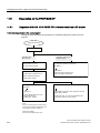
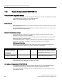
3.2.1
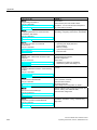
Overview of communication services
Selecting the communication service
You need to decide on a communication service, based on functionality requirements. Your
choice of communication service will have no effect on:
● The functionality available
● Whether an S7 connection is required or not
● The time of connecting
The user interface can vary considerably (SFC, SFB, ...), and is also determined by the
hardware used (IM 151-8 PN/DP CPU, PC, ...).
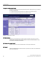
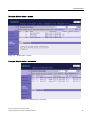
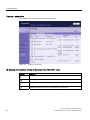
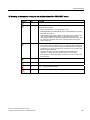
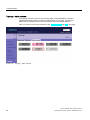
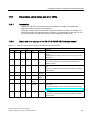
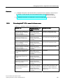
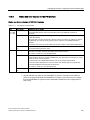
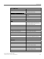
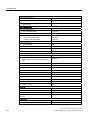
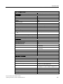
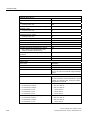
Overview of communication services
The table below provides an overview of the communication services provided by the
IM 151-8 PN/DP CPU interface module.
Table 3- 1
Communication services of the IM 151-8 PN/DP CPU interface module
Communication service
Functionality
Time at which the S7 connection is
established ...
via PN
via DP
(optional)
Programming device
communication
Commissioning, test,
diagnostics
From the programming device,
starting when the service is used
X
X
OP communication
Control and monitoring
From the OP at Power ON
X
X
S7 communication
Data exchange in server and
client mode: Configuration of
communication required
from the active partner at power on.
X
Only in
server
mode
Global data communication
Cyclic data exchange (for
example, bit memory)
Does not require an S7 connection
–
–
IM 151-8 PN/DP CPU interface module
Operating Instructions, 06/2010, A5E02049034-02
33
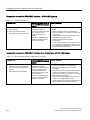
Communication
3.2 Communication services
Communication service
Functionality
Time at which the S7 connection is
established ...
via PN
via DP
(optional)
Routing programming
device functions
for example testing,
diagnostics on other networks
also
From the programming device,
starting when the service is used
X
X
Data set routing
e.g. configuration and
diagnostics of field devices on
PROFIBUS DP, if the PD with
the associated configuration
tool (e.g. PDM) is not
connection to the same
PROFIBUS DP subnet as that
of the field device, but, for
example, on the PROFINET
subnet at which the PN
interface of the IM 151-8
PN/DP CPU interface module
is also connected.
from the PD, starting when the
service is being used
X
X
PROFIBUS DP
Data exchange between
master and slave
Does not require an S7 connection
–
X
only as DP
master
PROFINET CBA
Data exchange by means of
component based
communication
Does not require an S7 connection
X
–
PROFINET IO
Data exchange between IO
controllers and the IO devices
Does not require an S7 connection
X
–
Web server
Diagnostics
Does not require an S7 connection
X
–
SNMP
Standard protocol for network
diagnostics and configuration
Does not require an S7 connection
X
–
Open communication by
means of TCP/IP
Data exchange via Industrial
Ethernet with TCP/IP protocol
(by means of loadable FBs)
Does not require an S7 connection, is X
handled in the user program by
means of loadable FBs
–
Open communication by
means of ISO on TCP
Data exchange via Industrial
Does not require an S7 connection, is X
Ethernet with ISO-on-TCP
handled in the user program by
protocol (by means of loadable means of loadable FBs
FBs)
–
Open communication by
means of UDP
Data exchange via Industrial
Does not require an S7 connection, is X
Ethernet with UDP protocol (by handled in the user program by
means of loadable FBs)
means of loadable FBs
–
Time synchronization
Broadcast telegrams
Does not require an S7 connection
–
X
Time synchronization
NTP protocol
Does not require an S7 connection
X
–
(Simple Network
Management Protocol)
See also
Distribution and availability of S7 connection resources (Page 47)
Connection resources for routing (Page 48)
34
IM 151-8 PN/DP CPU interface module
Operating Instructions, 06/2010, A5E02049034-02
Communication
3.2 Communication services
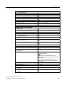
3.2.2
PG communication
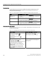
Properties
Programming device communication is used to exchange data between engineering stations
(programming device, PC, for example) and SIMATIC modules which are capable of
communication. This service is available via PROFIBUS and Industrial Ethernet subnets.
Transition between subnets is also supported.
Programming device communication provides the functions needed to download / upload
programs and configuration data, to run tests and to evaluate diagnostic information. These
functions are integrated in the operating system of the IM 151-8 PN/DP CPU interface
module.
An IM 151-8 PN/DP CPU interface module can maintain several simultaneous online
connections to one or multiple programming devices.
IM 151-8 PN/DP CPU without configured PROFINET interface
If your IM 151-8 PN/DP CPU interface module still does not have a configured PROFINET
interface (IP address), you can nevertheless communication from the PD with the IM 151-8
PN/DP CPU interface module.
● The IM 151-8 PN/DP CPU interface module logs on to the SIMATIC Manager with its
MAC address via "Available nodes".
If the Ethernet interface of the PD is set to "TCP/IP (Auto)", then during the first
establishment of a communication connection (e.g. call of the module status or the online
table of contents of the CPU), a temporary IP address is automatically assigned by the
PD to the PG interface of the IM 151-8 PN/DP CPU interface module. This is then
maintained until the next power off / power on or memory reset, or until a HW
configuration with a differing (retentive) IP address is loaded.
● Whilst downloading the parameters of the HW Config, the correct IP address can be
allocated to IM 151-8 PN/DP CPU interface module during the loading process. The
procedure for this can be found in section Connecting a PD / PC to the integrated
PROFINET interface of the an IM151-8 PN/DP CPU interface module.
● An IP address can be assigned to a PN interface in the SIMATIC manager under "Target
system > Edit Ethernet node". From V3.2 onward, this remains permanently stored.
IM 151-8 PN/DP CPU interface module
Operating Instructions, 06/2010, A5E02049034-02
35
Communication
3.2 Communication services
3.2.3
OP communication
Properties
OP communication is used to exchange data between operator CPUs (OP, TP, WinCC, for
example) and SIMATIC modules which are capable of communication. This service is
available via PROFIBUS and Industrial Ethernet subnets.
OP communication provides functions you require for monitoring and modifying. These
functions are integrated in the operating system of the IM 151-8 PN/DP CPU interface
module.
An IM 151-8 PN/DP CPU interface module can maintain several simultaneous online
connections to one or different OPs.
It is only after the PN interface of the IM 151-8 PN/DP CPU interface module has been
operated with a configured IP address that an OP be run on the interface.
3.2.4
S7 communication
Properties
The IM 151-8 PN/DP CPU interface module can act as either a server or a client in S7
communication. A distinction is made between:
● Communication with unilateral configuration (for PUT/GET only)
● Communication with bilateral configuration (for USEND, URCV, BSEND, BRCV, PUT,
GET)
The available functionality is described in the following table.
Table 3- 2
client and server in S7 communication, using connections with unilateral / bilateral
configuration
Interface module
Use in server mode for
connections with unilateral
configuration
IM 151-8 PN/DP CPU Usually possible at the
DP/PN interface without
programming the user
interface
Use in server mode for
connections with
bilateral configuration
Use as client
Possible at the PN
interface with loadable
FBs
Possible at the PN
interface with
loadable FBs
The user interface is implemented using standard function blocks (FBs) under
communication blocks in the standard STEP 7 library.
Reference
For additional information on communication, refer to the Communication with SIMATIC
manual.
36
IM 151-8 PN/DP CPU interface module
Operating Instructions, 06/2010, A5E02049034-02
Communication
3.2 Communication services
3.2.5
Routing
Properties
Using STEP 7 you can use the PD / PC via your IM 151-8 PN/DP CPU interface module
(with DP master module) to reach a CPU in a different subnet, in order, for example, to
● download user programs
● download a hardware configuration or
● perform tests and diagnostics functions.
Routing network nodes: PROFINET - PROFIBUS
Gateways between subnets are routed in a SIMATIC station that is equipped with interfaces
to the respective subnets. The figure below shows the access from PROFINET to
PROFIBUS. The CPU 1 (IM 151-8 PN/DP CPU with DP master module) is the router
between subnet 1 and subnet 2.
&38
,031'3&38
'30DVWHUPRGXO
31
6XEQHW 352),1(7
&38
,0&38
'3
0DVWHU
'3
VODYHDFWLYH
6XEQHW 352),%86
3*
Number of connections for routing
A maximum of 4 connections are available on the PROFINET interface of the IM
151-8 PN/DP CPU interface module for the routing function.
IM 151-8 PN/DP CPU interface module
Operating Instructions, 06/2010, A5E02049034-02
37
Communication
3.2 Communication services
Requirements
● The station modules are "capable of routing" (CPUs or CPs).
● The network configuration does not exceed project limits.
● The modules have loaded the configuration data containing the latest "knowledge" of the
entire network configuration of the project.
Reason: All modules participating in the network transition must receive the routing
information defining the paths to other subnets.
● In your network configuration, the programming device/PC you want to use to establish a
connection via network node must be assigned to the network it is physically connected
to.
Reference
Additional information
● About configuring with STEP 7 can be found in the Configuring Hardware and
Connections in STEP 7 manual
● On communication are found in the Communication with SIMATIC Manual.
● On SFCs, refer to the S7-300 Instruction List.
A detailed description is given in the STEP 7 Online Help or System and Standard
Functions for S7-300/400 Reference Manual.
3.2.6
Data set routing
Availability
The IM 151-8 PN/DP CPU interface module supports data set routing if a DP master module
is connected to it.
Routing and data set routing
Routing is the transfer of data beyond network boundaries. You can send information from a
transmitter to a receiver across several networks.
Data record routing is an expansion of the "standard routing" and is used, for example, by
SIMATIC PDM. The data sent through data set routing includes the parameters for the
participating field devices (slaves) as well as device-specific information (e.g. setpoint
values, limit values, etc.). The structure of the target address for data record routing depends
on the data contents, i.e. the slave to which the data is to be sent.
With the PD, e.g. a parameter set that already exists on the field device can be read, edited
and then sent back to the field device if the PD is not connected to the same PROFIBUS DP
subnet as that of the field device.
The field devices themselves do not have to support data set routing, since they do not
forward the information received.
38
IM 151-8 PN/DP CPU interface module
Operating Instructions, 06/2010, A5E02049034-02
Communication
3.2 Communication services
Data set routing
The following figure shows the access of the PD to a variety of field devices. In doing so, the
PD is connected via PROFINET to the IM 151-8 PN/DP CPU interface module. The
IM 151-8 PN/DP CPU interface module communicates via PROFIBUS with the field devices.
3URJUDPPLQJGHYLFHbb3&
ZLWK6,0$7,&3'0
352),1(7
(76
352),%86'3
'33$OLQN
(70
P$
+$57
352),%863$
6,02&2'(
Figure 3-1
IM 151-8 PN/DP CPU data set routing
See also
You can find additional information on SIMATIC PDM in the The Process Device Manager
Manual.
IM 151-8 PN/DP CPU interface module
Operating Instructions, 06/2010, A5E02049034-02
39
Communication
3.3 SNMP communication service
3.2.7
Data consistency
Properties
A data area is consistent if it can be read or written to from the operating system as a
consistent block. Data exchanged collectively between the stations should belong together
and originate from a single processing cycle, that is, be consistent. If the user program
contains a programmed communication function, for example,
FB 12 "BSEND" / FB 13 "BRCV", which accesses shared data, access to that data area can
be coordinated by means of the "BUSY" parameter itself.
With PUT/GET functions
For S7 communication functions, such as PUT / GET or write / read via OP communication,
which do not require a block in the user program on the IM151-8 PN/DP CPU interface
module (acting as a server), allowances must be made in the programming for the extent of
the data consistency. The PUT / GET functions for S7 communication, or for read / write
variables via OP communication, are executed at the IM151-8 PN/DP CPU interface
module´s cycle control point. In order to ensure a defined process interrupt reaction time,
communication variables are copied consistently in blocks of up to 240 bytes to/from the
user memory at the operating system's cycle control point. Data consistency is not
guaranteed for larger data areas.
Note
If defined data consistency is required, the length of the communication variables in the
IM151-8 PN/DP CPU interface module operating system's user program must not exceed
240 bytes.
3.3
SNMP communication service
Availability
The SNMP communication service is available for the IM 151-8 PN/DP CPU interface
module with integrated PROFINET interface.
Properties
SNMP (Simple Network Management Protocol) is a standard protocol for TCP/IP networks.
Reference
For additional information on the SNMP communication service and diagnostics with SNMP,
refer to the PROFINET System Description.
40
IM 151-8 PN/DP CPU interface module
Operating Instructions, 06/2010, A5E02049034-02
Communication
3.4 Open communication via Industrial Ethernet
3.4
Open communication via Industrial Ethernet
Requirement
● STEP 7 V5.4 + Servicepack 4 or higher
Functionality
The IM 151-8 PN/DP CPU interface module with integrated PROFINET interface supports
open communication functionality via Industrial Ethernet (abbreviated to open IE
communication).
The following services are available for open IE communication:
● Connection oriented protocols
– TCP to RFC 793, connection type B#16#01
– TCP to RFC 793, connection type B#16#11
– ISO on TCP to RFC 1006
● Connectionless protocols
– UDP according to RFC 768
Features of the communication protocols
The following distinctions are made between protocol types in data communication:
● Connection oriented protocols:
Prior to data transmission these establish a (logical) connection to the communication
partner and close this again, if necessary, after transmission is completed. Connection
oriented protocols are used when security in especially important in data transmission. A
physical cable can generally accommodate several logical connections.
For the FBs to open communication by means of Industrial Ethernet, the following
connection oriented protocols are supported:
– TCP according to RFC 793 (connection types B#16#01 and B#16#11)
– ISO on TCP according to RFC 1006 (connection type B#16#12)
● Connectionless protocols:
These operate without a connection. There is also no establishing or terminating a
connection to remote partner. Wireless protocols transmit data to the remote partner
without any acknowledgement; data transfer is, therefore, not secure.
The FBs for open communication over Industrial Ethernet support the following wireless
protocol:
– UDP according to RFC 768 (connection type B#16#13)
IM 151-8 PN/DP CPU interface module
Operating Instructions, 06/2010, A5E02049034-02
41
Communication
3.4 Open communication via Industrial Ethernet
How to use open IE communication
To allow data to be exchanged with other communication partners, STEP 7 provides the
following FBs and UDTs under "Communication Blocks" in the "Standard Library":
● Connection oriented protocols: TCP/ISO-on-TCP
– FB 63 "TSEND" for sending data
– FB 64 "TRCV" for receiving data
– FB 65 "TCON", for connecting
– FB 66 "TDISCON", for disconnecting
– UDT 65 "TCON_PAR" with the data structure for the configuration of the connection
● Connectionless protocol: UDP
– FB 67 "TUSEND" for sending data
– FB 68 "TURCV" for receiving data
– FB 65 "TCON" for establishing the local communication access point
– FB 66 "TDISCON" for resolving the local communication access point
– UDT 65 "TCON_PAR" with the data structure for configuring the local communication
access point
– UDT 66 "TCON_ADR" with the data structure of the address parameters of the remote
partner
Data blocks for the configuration of the connection
● Data blocks for assigning parameters for TCP and ISO-on-TCP connections
To assign parameters for your connection at TCP and ISO-on-TCP, you need to create a
DB that contains the data structure of UDT 65 "TCON_PAR." This data structure contains
all parameters you need to establish the connection. You need to create such a data
structure for each connection, and you can also organize it in a global DB.
Connection parameter CONNECT of FB 65 "TCON" reports the address of the
corresponding connection description to the user program (for example,
P#DB100.DBX0.0 byte 64).
● Data blocks for the configuration the local UDP communication access point
To assign parameters for the local communication access point, create a DB containing
the data structure from the UDT 65 "TCON_PAR" This data structure contains the
required parameters you need to establish the connection between the user program and
the communication level of the operating system
The CONNECT parameter of the FB 65 "TCON" contains a reference to the address of
the corresponding connection description (e.g. P#DB100.DBX0.0 Byte 64).
Note
Setting up the connection description (UDT 65)
You must enter the interface to be used for communication in the "local_device_id"
parameter in UDT 65 "TCON_PAR" (e.g. B#16#01: Communication via the integrated PN
interface of the IM 151-8 PN/DP CPU interface module).
42
IM 151-8 PN/DP CPU interface module
Operating Instructions, 06/2010, A5E02049034-02
Communication
3.4 Open communication via Industrial Ethernet
Establishing a connection for communication
● Use with TCP and ISO-on-TCP
Both communication partners call FB 65 "TCON" to establish the connection. In your
connection configuration, you define which communication partner activates the
connection, and which communication partner responds to the request with a passive
connection. To determine the number of possible connections, refer to your
IM 151-8 PN/DP CPU interface module´s technical specifications.
The IM 151-8 PN/DP CPU interface module automatically monitors and maintains the
established connection.
If the connection is broken, for example by line interruption or by the remote
communication partner, the active partner tries to reestablish the connection. You do not
have to call FB 65 "TCON" again.
FB 66 "TDISCON" disconnects the IM 151-8 PN/DP CPU interface module from a
communication partner, as does STOP mode. To reestablish the connection to have to
call FB65 "TCON" again.
● Use with UDP
Both communication partners call FB 65 "TCON" to set up their local communication
access point. This establishes a connection between the user program and operating
system's communication level No connection is established to the remote partner.
The local access point is used to send and receive UDP message frames.
Disconnecting
● Use with TCP and ISO-on-TCP
FB 66 "TDISCON" disconnects the communication connection between the
IM 151-8 PN/DP CPU interface module and a communication partner.
● Use with UDP
FB 66 "TDISCON" disconnects the local communication access point, i.e., the connection
between the user program and the communication layer of the operating system is
interrupted.
Options for interrupting the communication connection
Events causing interruptions of communication:
● You program the cancellation of connections at FB 66 "TDISCON."
● The IM 151-8 PN/DP CPU interface module changes from RUN to STOP.
● With POWER OFF / POWER ON
Reference
For detailed information on the blocks described earlier, refer to the STEP 7 Online Help.
IM 151-8 PN/DP CPU interface module
Operating Instructions, 06/2010, A5E02049034-02
43
Communication
3.5 S7 connections
3.5
S7 connections
3.5.1
S7 connection as communication path
An S7 connection is established when S7 modules communicate with one another. This S7
connection is the communication path.
Note
No S7 connections are required for communication via PROFIBUS DP, PROFINET CBA,
PROFINET IO, web server, TCP/IP, ISO on TCP, UDP and SNMP.
Each communication link requires S7 connection resources on the IM151-8 PN/DP CPU
interface module for the entire duration of this connection.
Thus, each IM151-8 PN/DP CPU interface module is provided with a specific number of S7
connection resources. These are used by various communication services (PG / OP
communication or S7 communication).
Connection points
An S7 connection between modules with communication capability is established between
connection points. The S7 connection always has two connection points: The active and
passive connection points:
● The active connection point is assigned to the module that establishes the S7 connection.
● The passive connection point is assigned to the module that accepts the S7 connection.
Any module that is capable of communication can thus act as an S7 connection point. At the
connection point, the established communication link always uses one S7 connection of the
module concerned.
Transition point
If you use the routing functionality, the S7 connection between two modules capable of
communication is established across a number of subnets. These subnets are
interconnected via a network transition. The module that implements this network transition
is known as a router. The router is thus the point through which an S7 connection passes.
Each IM 151-8 PN/DP CPU interface module (with DP master module) can be a route for an
S7 connection. You can establish a certain maximum number of routing connections. This
does not limit the data volume of the S7 connections.
See also
Connection resources for routing (Page 48)
44
IM 151-8 PN/DP CPU interface module
Operating Instructions, 06/2010, A5E02049034-02
Communication
3.5 S7 connections
3.5.2
Assignment of S7 connections
There are several ways to allocate S7 connections on a communication-capable module:
● Reservation during configuration
● Assigning connections in the program
● Allocating connections during commissioning, testing and diagnostics routines
● Allocating connection resources to HMI services
Reservation during configuration
One connection resource each is automatically reserved on the IM151-8 PN/DP CPU
interface module for programming device and OP communication. Whenever you need more
connection resources (for example, when connecting several OPs), configure this increase in
the IM151-8 PN/DP CPU interface module properties dialog box in STEP 7.
Connections must also be configured (using NetPro) for the use of S7 communication. For
this purpose, connection resources have to be available, which are not allocated to
programming device/OP or other connections. The required S7 connections are then
permanently allocated for S7 communication when the configuration is uploaded to the
IM151-8 PN/DP CPU interface module.
Assigning connections in the program
In open Industrial Ethernet communication with TCP/IP, the user program establishes the
connection. In doing so, the operating system of the IM151-8 PN/DP CPU interface module
initiates the connection. The open IE communication does not use any S7 connections. The
maximum number of eight connections also applies to this type of communication.
Using connections for commissioning, testing and diagnostics
An active online function on the engineering station (programming device /PC with STEP 7)
assigns S7 connections for programming device communication:
● An S7 connection resource for programming device communication which was reserved
in your IM151-8 PN/DP CPU interface module hardware configuration is assigned to the
engineering station, that is, it just needs to be allocated.
● If all reserved S7 connection resources for programming device communication are
allocated, the operating system automatically assigns a free S7 connection resource
which has not yet been reserved. If no more connection resources are available, the
engineering station cannot communicate online with the IM151-8 PN/DP CPU interface
module.
IM 151-8 PN/DP CPU interface module
Operating Instructions, 06/2010, A5E02049034-02
45
Communication
3.5 S7 connections
Allocating connection resources to HMI services
An online function on the HMI station (OP/TP/... with WinCC) is used for assigning S7
connection resources for the OP communication:
● An S7 connection resource for programming device communication which was reserved
in your IM151-8 PN/DP CPU interface module hardware configuration is assigned to the
HMI station, that is, it just needs to be allocated.
● If all reserved S7 connection resources for OP communication are allocated, the
operating system automatically assigns a free S7 connection resource which has not yet
been reserved. If no more connection resources are available, the HMI station cannot
communicate online with the IM151-8 PN/DP CPU interface module.
Chronological order in which S7 connection resources are assigned
When you program your project in STEP 7, the system generates parameter assignment
blocks which are read by the modules in the startup phase. This allows the module's
operating system to reserve or assign the relevant S7 connection resources. This means, for
example, that OPs cannot access an S7 connection resource that has been reserved for
programming device communication. If the IM151-8 PN/DP CPU interface module has S7
connection resources that have not been reserved, these can be used freely. These S7
connection resources are allocated in the order they are requested.
Example
If there is only one free S7 connection left on the IM151-8 PN/DP CPU interface module, you
can still connect a programming device to the bus. The programming device can then
communicate with the IM151-8 PN/DP CPU interface module. However, the S7 connection
will always be used if the PD is communicating with the IM151-8 PN/DP CPU interface
module. If you connect an OP to the bus while the programming device is not
communicating, the OP can establish a connection to the IM151-8 PN/DP CPU interface
module. Since an OP maintains its communication link at all times, in contrast to the PG, you
cannot subsequently establish another connection via the PG.
See also
Open communication via Industrial Ethernet (Page 41)
46
IM 151-8 PN/DP CPU interface module
Operating Instructions, 06/2010, A5E02049034-02
Communication
3.5 S7 connections
3.5.3
Distribution and availability of S7 connection resources
Distribution of connection resources
Table 3- 3
Distribution of connections
Communication service
Distribution
Programming device communication
In order to avoid allocation of connection resources being dependent only on
the chronological sequence in which various communication services are
requested, connection resources can be reserved for these services.
OP communication
S7 basic communication
For PG and OP communication, at least one connection resource is reserved
by default.
The following table and the technical specifications for the IM1518 PN/DP CPU interface module contain the configurable S7 connections and
the default setting. You "redistribute“ the connection resources by setting the
relevant IM151-8 PN/DP CPU interface module parameters in STEP 7.
S7 communication
Available connection resources that are not specially reserved for a service
(programming device / OP communication, S7 basic communication) are used
for this.
Routing PG functions
Together with the DP master module, the IM 151-8 PN/DP CPU interface
module has a number of connection resources available for routing purposes.
These connections are available in addition to the connection resources.
The subsection below shows the number of connection resources.
PROFIBUS DP
This communication service requires no S7 connection resources.
PROFINET CBA
This communication service requires no S7 connection resources.
PROFINET IO
This communication service requires no S7 connection resources.
Web server
This communication service requires no S7 connection resources.
Open communication via TCP/IP
This communication service requires no S7 connection resources.
Open communication by means of ISO on Independently of the S7 connections, a total of 8 own resources are available
for connections or local access points (UDP) for TCP/IP, ISO on TCP, UDP.
TCP
Open communication by means of UDP
SNMP
IM 151-8 PN/DP CPU interface module
Operating Instructions, 06/2010, A5E02049034-02
This communication service requires no S7 connection resources.
47
Communication
3.5 S7 connections
Availability of connection resources
Table 3- 4
Availability of connection resources
Interface module
Total number
connection
resources
IM 151-8 PN/DP CPU
12
Reserved for
Programming
device
communication
OP
communication
S7 basic
communication
1 to 11
default 1
1 to 11
default 1
0 to 10
default 0
Free
S7 connections
Displays all nonreserved S7
connections as free
connections.
Note
If you are using the IM151-8 PN/DP CPU interface module, you can configure up to 10
connection resources for S7 communication in NetPro. These connections are then
reserved.
3.5.4
Connection resources for routing
Number of connection resources for routing
In addition to the S7 connection resources, a maximum of 4 connections are available on the
PROFINET interface of the IM151-8 PN/DP CPU interface module for the routing function.
Routing is only possible if the DP master module is connected and configured.
Example for the IM 151-8 PN/DP CPU
The IM 151-8 PN/DP CPU interface module makes available 12 connection resources:
● Reserve two connection resources for programming device communication.
● Reserve two connection resources for OP communication.
● In NetPro you configure 3 S7 connection resources for S7 communication via the
integrated PROFINET interface.
This leaves 5 S7 connections available for any communication services, e.g. S7
communication, OP communication, etc.
However, no more than 10 connection resources for S7 communication at the integrated PN
interface can be configured in NetPro.
There are also 4 routing connections available for the IM151-8 PN/DP CPU interface module
that do not affect the S7 connection resources mentioned above.
48
IM 151-8 PN/DP CPU interface module
Operating Instructions, 06/2010, A5E02049034-02
Communication
3.6 DPV1
3.6
DPV1
New automation and process engineering tasks require the range of functions performed by
the existing DP protocol to be extended. In addition to cyclical communication functions,
acyclical access to non-S7 field devices is another important requirement of our customers,
and was implemented in the EN 50170 standard. In the past, acyclic access was only
possible with S7 slaves. The standard concerning distributed I/Os (EN 50170) has been
further developed. All the changes concerning new DPV1 functions are included in IEC
61158/ EN 50170, volume 2, PROFIBUS.
Definition DPV1
The term DPV1 is defined as a functional extension of the acyclic services (to include new
interrupts, for example) provided by the DP protocol.
Availability
Together with the DP master module you can operate the IM 151-8 PN/DP CPU interface
module as a DP master via the expanded DPV1 functionality.
Requirement for using the DPV1 functionality with DP slaves
For DPV1 slaves from other vendors, you will need a GSD file conforming to EN 50170,
revision 3 or later.
Extended functions of DPV1
● Use of any DPV1 slaves from external vendors (in addition to the existing DPV0 and S7
slaves, of course).
● Selective handling of DPV1-specific interrupt events by new interrupt blocks.
● Reading/writing SFBs that conform to standards to the data record (although this can only
be used for centralized I/O modules).
● User-friendly SFB for reading diagnostics.
IM 151-8 PN/DP CPU interface module
Operating Instructions, 06/2010, A5E02049034-02
49
Communication
3.6 DPV1
Interrupt blocks with DPV1 functionality
Table 3- 5
Interrupt blocks with DPV1 functionality
OB
Functionality
OB 40
Process interrupt
OB 55
Status interrupt
OB 56
Update interrupt
OB 57
Vendor-specific interrupt
OB 82
Diagnostic interrupt
Note
You can now also use organization blocks OB40 and OB82 for DPV1 interrupts.
System blocks with DPV1 functionality
Table 3- 6
SFB
System function blocks with DPV1 functionality
Functionality
SFB 52
Read data record from DP slave / IO device or centralized I/O module
SFB 53
Write data record to DP slave / IO device or centralized I/O module
SFB 54
Read additional alarm information from a DP slave / IO device or a centralized I/O
module in the relevant OB
SFB 75
Set any interrupts for intelligent slaves
Note
You can also use SFB 52 to SFB 54 for centralized I/O modules. SFBs 52 to 54 can also be
used for PROFINET IO.
Reference
For additional information on the above blocks can be found in the System and Standard
Functions for S7-300/400 reference manual, or in the STEP 7 Online Help.
See also
PROFIBUS DP (Page 32)
50
IM 151-8 PN/DP CPU interface module
Operating Instructions, 06/2010, A5E02049034-02
Communication
3.7 Web server
3.7
Web server
Introduction
The web server allows you to monitor your IM 151-8 PN/DP CPU interface module over the
Internet or your company's intranet. This allows analyses and diagnostics to be carried out
remotely.
Messages and status information are displayed on HTML pages.
Web browser
You will need a web browser to access the HTML pages for the IM 151-8 PN/DP CPU
interface module .
The following web browsers are suitable for communication with the IM 151-8 PN/DP CPU
interface module:
● Internet Explorer (version 6.0 or later)
● Mozilla Firefox (version 1.5 or later)
● Opera (version 9.0 or later)
● Netscape Navigator (version 8.1 or later)
Reading information via the web server
Via the web server, you can read the following information from the IM 151-8 PN/DP CPU
interface module:
● firmware V2.7 or later
– Start page with general information
– Identification data
– Contents of the diagnostics buffer
– Messages (without acknowledgment option)
– - PROFINET (communication)
– Variable status
– Variable tables
● from firmware V3.2 and configuration with STEP 7 V5.5
– Module state
– Communication: Display the OUC connections and the resources
– Topology: Display the setpoint and current topology from the configuration
– User pages (WEB2PLC required)
The following pages describe the HTML pages and contain detailed explanatory notes.
IM 151-8 PN/DP CPU interface module
Operating Instructions, 06/2010, A5E02049034-02
51
Communication
3.7 Web server
Web access to the IM 151-8 PN/DP CPU interface module via PD / PC
Proceed as follows to access the web server:
1. Connect the client (programming device or PC) to the IM 151-8 PN/DP CPU interface
module via the PROFINET interface.
2. Open the web browser (e.g. Internet Explorer).
Enter the IP address of the IM 151-8 PN/DP CPU interface module in the "Address" field
of the web browser in the format http://a.b.c.d or https://a.b.c.d (for example:
http://192.168.3.141).
The start page of the IM 151-8 PN/DP CPU interface module opens. From the start page
you can navigate to additional information.
Note
Up to 5 http / https connections are possible.
Web access to the IM 151-8 PN/DP CPU interface module via HMI devices and PDA
The web server also supports the Windows terminal service which means that thin client
solutions with mobile devices (e.g. PDA or MOBIC T8) and robust local stations (e.g.
SIMATIC MP370 with the ThinClient/MP option) can be implemented under Windows CE, in
addition to the use of programming devices and PCs.
Proceed as follows to access the web server:
1. Connect the client (HMI device, PDA) to the IM 151-8 PN/DP CPU interface module via
the PROFINET interface.
2. Open the web browser (for example, Internet Explorer).
Enter the IP address of the IM 151-8 PN/DP CPU interface module in the "Address" field
of the web browser in the format http://a.b.c.d/basic or https://a.b.c.d/basic (for example:
http://192.168.3.141/basic).
The start page of the IM 151-8 PN/DP CPU interface module opens. From the start page
you can navigate to additional information.
The IM 151-8 PN/DP CPU interface module information is processed in a specially-designed
browser for HMI devices running under Windows CE earlier than V 5.x. The information
appears in a simplified format in this browser. The following illustrations show the detailed
form respectively.
52
IM 151-8 PN/DP CPU interface module
Operating Instructions, 06/2010, A5E02049034-02
Communication
3.7 Web server
Web servers without SIMATIC Micro Memory Card
Note
Using SIMATIC Micro Memory Card together with Web server
The configuration data for the Web server is stored on the SIMATIC Micro Memory Card. We
therefore recommend that you use a SIMATIC Micro Memory Card with at least 512 kB.
You can also use the web server without the SIMATIC Micro Memory Card inserted The
condition for operation is that you have assigned an IP address to the IM 151-8 PN/DP CPU
interface module.
The content of the diagnostics buffer is displayed in hex code.
Start page, identification and communication information as well as variable status are
displayed in plain text.
Following displays remain empty:
– Module state
– Messages
– Topology
– Variable tables
– User pages
Automatic page updating is activated by default with no need for configuration.
Security
The web server offers the following security functions:
● Access via the secure transmission protocol https
● configurable user rights via the user list
In addition, protect your web-compliant IM 151-8 PN/DP CPU interface module against
unauthorized access by means of a firewall.
See also
Language settings (Page 54)
IM 151-8 PN/DP CPU interface module
Operating Instructions, 06/2010, A5E02049034-02
53
Communication
3.7 Web server
3.7.1
Language settings
Display languages
The web server provides messages and diagnostics information in the following languages:
● German (Germany)
● English (United States)
● French (France)
● Italian (Italy)
● Spanish (traditional sorting)
● Simplified Chinese
● Japanese
Both Asian languages can be combined as follows:
● Chinese with English
● Japanese with English
Conditions for the availability of Asian languages
The following conditions must be fulfilled for the Asian languages Chinese and Japanese:
● The respective language package has been installed on the viewing device (e.g. PC).
● STEP 7 for Asian languages (V5.5) is installed on the PD for the configuration of the
IM 151-8 PN/DP CPU interface module.
Note
SIMATIC HMI devices running the Windows CE operating system do not support any
Asian languages.
What you need to display texts in different languages
You must make two language settings in STEP 7 so that the web server displays the various
languages correctly.
● Setting the language for display devices in SIMATIC Manager
● Set the language for the web in the IM 151-8 PN/DP CPU interface module Properties
dialog. For further information, refer to section Settings in HW Config, "Web" tab.
54
IM 151-8 PN/DP CPU interface module
Operating Instructions, 06/2010, A5E02049034-02
Communication
3.7 Web server
Setting the language for display devices in SIMATIC Manager
Select the languages for display devices in SIMATIC Manager:
Options > Language for display devices
Figure 3-2
Example for selecting the display device language
IM 151-8 PN/DP CPU interface module
Operating Instructions, 06/2010, A5E02049034-02
55
Communication
3.7 Web server
3.7.2
Settings in HW Config, "Web" tab
Requirements
You have opened in HW Config the Properties dialog for the IM 151-8 PN/DP CPU interface
module.
To use the full functionality of the web server, carry out the following settings in the "Web"
tab:
● Activating the web server
● Set the language for Web
● Adding to the user list
● Access activation for HTTPS
● Activate automatic update
● Display classes of the messages
① Activate the web server
The web server is deactivated in HW Config by default. You activate the web server in HW
Config.
In the CPU properties dialog:
● Check the "Activate web server on this module" check box.
56
IM 151-8 PN/DP CPU interface module
Operating Instructions, 06/2010, A5E02049034-02
Communication
3.7 Web server
② Set the language for web
Select up to two languages for the Web from the languages installed for display devices.
In the CPU properties dialog:
● Check the "Activate Web server on this module" check box
● Select up to two languages for the Web.
Note
If you activate the web server and do not select a language, messages and diagnostic
information will be displayed in hexadecimal code.
③ User list
The user list offers you the options to:
● create users,
● specify execution rights,
● assign passwords.
This assignment ensures that the users have access to precisely those options that are
specified for those execution rights.
● If no users are specified in the hardware configuration, read-only access is granted to all
web pages.
● If users are configured, until a user has logged in he/she has access only to the intro and
the start page.
● Once a user is configured and logged in, he/she can access the web pages in
accordance with his access rights.
● If a special user is configured with the login "everybody", a user who has not logged in
has access without prior input of the password to those pages that are enabled for
access by "everybody".
If, for instance, "everybody" has the access right to "Read variables", the "Variables table"
web page is displayed by default in the main menu bar without prior input of the
password.
A maximum of 20 users and "everybody" users can be set up.
④ Access only by HTTPS
https ensures encryption of the communication between the browser and web server.
For error-free https access to the IM, the following is required:
● The current time must be set in the IM.
● IP address of the IM (for example, input https://192.168.3.141)
● You require an installed and valid certificate
If no certificate is installed, a warning is displayed with the recommendation not to use the
page. To view the page, the user must then explicitly "Add an exception".
A valid certificate (Certification Authority) can be obtained as a download from the "Intro"
web page under "Download certificate". For instructions on how to install the certificate, see
the "Help" for your respective web browser.
An encrypted connection is shown by a padlock icon in the status bar of the web page.
IM 151-8 PN/DP CPU interface module
Operating Instructions, 06/2010, A5E02049034-02
57
Communication
3.7 Web server
⑤ Activate automatic update
The following web pages can be updated automatically:
● Start page
● Diagnostics buffer
● Module state
● Messages
● Information about communication
● Topology
● Variable status
● Variable table
To enable automatic updates, proceed as follows:
● Set the "Activate" check box at "Automatic update" in the properties dialog of the IM
(under the "Web" tab)
● Enter the update interval.
Note
Update time
The activation interval set in the HW Config represents the shortest update time. Larger
amounts of data or several http / https connections increase the update time.
⑥ Display classes of the messages
All message display classes are activated in the basic configuration in HW Config. The
messages for the selected display classes are displayed later on the "Messages" web page.
Messages for display classes that are not selected are shown as hexadecimal code and not
as plain text.
How to configure the message classes:
● For "Report system error" in HW Config under Options > Report system error
● For block-specific messages in STEP 7
Information about configuring message texts and classes can be found in STEP 7.
Note
Reducing the memory requirement of web SDBs
You can reduce the memory requirement of web SDBs by selecting just the message display
classes that are to be filled in the web SDB.
58
IM 151-8 PN/DP CPU interface module
Operating Instructions, 06/2010, A5E02049034-02
Communication
3.7 Web server
3.7.3
Updating and saving information
Screen content refresh status and printing
Screen content
Automatic updating is deactivated in HW Config by default.
This means that the screen of the Web server outputs static information.
Refresh the Web pages manually using the <F5> function key or the following icon:
Update status of printouts
Data output to the printer always returns the current interface module information. It is
therefore possible that the information output to the printer may be more current than the
screen contents.
To obtain a print preview of the web page, click the icon:
Filter settings have no effect on the print-out, The printout of the "Messages" and "Module
status" web pages always shows the complete content of the pages.
Disabling automatic update for an individual web page
To deactivate automatic refresh for a Web page for a short time, select the following icon:
Enable automatic refresh again using the <F5> function key or the following icon:
Saving messages and entries of the diagnostics buffer
Messages and diagnostics buffer entries can be saved to a csv file. Use the following symbol
to save the data.
A dialog box opens in which you can enter the file name and target directory.
To prevent incorrect display of the data in Excel, do not open the csv file with double-click.
Import the file in Excel by selecting the "Data" and "Import external data" menu command.
IM 151-8 PN/DP CPU interface module
Operating Instructions, 06/2010, A5E02049034-02
59
Communication
3.7 Web server
3.7.4
Web pages
3.7.4.1
Start page with general CPU information
Establishing a connection to the web server
Connect to the web server by entering the IP address of the configured IM151-8 PN/DP CPU
interface module on the web browser's address bar (e.g. http: //192.168.1.158 or https:
//192.168.1.158). The connection is established and the "Intro" page opens.
Note
Here we show and explain by way of examples, how the various web pages may appear.
Intro
The web server calls the following page upon start-up:
Figure 3-3
60
Intro
IM 151-8 PN/DP CPU interface module
Operating Instructions, 06/2010, A5E02049034-02
Communication
3.7 Web server
Click on the ENTER link to access the web server pages.
Note
Skip website intro
Check the "Skip Intro" check box to skip the intro. You will then access the web server's start
page directly in future. You can reverse the "Skip intro" setting by clicking on the "Intro" link
on the start page.
Start page
The start page contains information as shown below. The image of the IM151-8 PN/DP CPU
interface module with LEDs reflects your current status at the time of checking the data.
Figure 3-4
Start page before login
Login
In order to use the full functionality of the web pages, you must be logged in: Log in using
one of the user names and passwords specified in the WEB configuration for the hardware.
You then have the user's access rights to the web pages assigned to them. For further
information, refer to section Settings in HW Config, "Web" tab (Page 56).
IM 151-8 PN/DP CPU interface module
Operating Instructions, 06/2010, A5E02049034-02
61
Communication
3.7 Web server
① "General"
Information about the IM151-8 PN/DP CPU interface module, the web server with which you
are currently connected, is combined in this group.
② "Status"
Status information about the IM151-8 PN/DP CPU interface module at the time of the query
is displayed in the "Status" info field.
Reference
Further information about http / https connections can be found in section Settings in HW
Config, "Web" tab (Page 56).
3.7.4.2
Identification
Characteristics
The "Identification" web page contains the characteristic data for the IM151-8 PN/DP CPU
interface module.
Figure 3-5
62
Identification
IM 151-8 PN/DP CPU interface module
Operating Instructions, 06/2010, A5E02049034-02
Communication
3.7 Web server
① "Identification"
The "Identification" info field contains the system and location designations as well as the
serial number.
Plant and location designations can be configured in HW Config in the properties dialog box
of the IM, "General" tab.
② "Order number"
The "Order number" info field contains order numbers for the hardware and software.
③ "Version"
The hardware, firmware and boot loader versions are displayed in the "Version" info field.
IM 151-8 PN/DP CPU interface module
Operating Instructions, 06/2010, A5E02049034-02
63
Communication
3.7 Web server
3.7.4.3
Diagnostic buffer
Diagnostics buffer
The browser displays the content of the diagnostics buffer on the "Diagnostics buffer" web
page.
Figure 3-6
Diagnostics buffer
Requirement
You must have activated the web server, made the language setting and compiled and
loaded the project in STEP 7.
64
IM 151-8 PN/DP CPU interface module
Operating Instructions, 06/2010, A5E02049034-02
Communication
3.7 Web server
① "Diagnostics buffer entries 1-100"
The diagnostics buffer may contain up to 500 messages. Select an interval for the buffer
entries from the list box. Each interval contains 100 entries.
For interface modules ≥ V3.2, the number of the displayed diagnostic buffer entries in the
RUN can be assigned parameters between 10 and 499 in the properties dialog of the CPU
("Diagnostics / Clock" tab). In RUN, 10 entries are set as default.
② "Events"
The "Events" info field contains the diagnostic events with the date and time.
③ "Details"
This box contains detailed information about the selected event.
Select the event from the ② "Events" info field.
Configuration
Configuration involves the following steps:
1. Select the "Object properties" dialog box from the context menu of the relevant IM1518 PN/DP CPU interface module.
2. Select the "Web" tab and check the "Activate web server on this module" check box.
3. Select up to two languages to be used to display plaintext messages.
4. Save and compile the project and download it to the IM151-8 PN/DP CPU interface
module.
Point to note when changing between languages
You can change the language, e.g. from German to English, in the top right-hand corner. If
you select a language that you have not configured, then the information will appear as
hexadecimal code, rather than in plaintext.
IM 151-8 PN/DP CPU interface module
Operating Instructions, 06/2010, A5E02049034-02
65
Communication
3.7 Web server
3.7.4.4
Module state
Requirements
● You have carried out the following settings in HW Config:
– Web server activated
– Language settings carried out
– "Report system error" generated and activated
● You have compiled the project using STEP 7 HW Config, loaded the SDB container and
the user program (in particular the user program blocks generated by "Report system
error")
● The IM is in RUN mode.
Note
"Report system error"
Duration of the display: Depending on the plant extension level, the "Report system
error" display requires some time to create the initial evaluation of the state of all the
configured I/O modules and I/O systems. During this time there is no concrete display
of the status on the "Module status" web page. A "?" is displayed in the "Status"
column.
Dynamic response: "Report system error" has to be called up cyclically at least every
100 ms.
Calling up can take place in OB 1, or if the cycle time amounts to more than 100 ms,
in the watchdog interrupt OB 3x (≤ 100 ms) and in the restart OB 100.
Diagnostics support: In the "Report system error" dialog box, the "Diagnostic status
DB" tab must be selected in the "Diagnostics support" tab and a DB number entered.
This check box is normally selected as default with configured Web servers. During
the migration of old project, it may however be necessary to select this check box.
66
IM 151-8 PN/DP CPU interface module
Operating Instructions, 06/2010, A5E02049034-02
Communication
3.7 Web server
Status of the modules
The state of a station is indicated by means of symbols and comments on the "Module
status" web page.
Figure 3-7
Module status - station
Meaning of the symbols in the "Status" column
Symbol
Color
green
Meaning
Component OK
gray
Disabled PROFIBUS slaves or PROFINET devices
Support conditions:
IM151-8 PN/DP CPU ≥ V3.2 and STEP 7 V5.5
Enabling/disabling the PROFIBUS slaves and PROFINET IO devices using
SFC12 mode 3/4
In the "Report System Error" dialog, in the "Diagnostics support" tab, area
"Status activated/deactivated", a check must be set in the "Device
interrogation for status 'activated/deactivated' after CPU start-up" check box,
optionally also in the "Generate alarm at change of status" check box.
black
Component cannot be accessed/Status cannot be determined
The "Status cannot be determined" is, for example, always displayed in the
STOP mode of the CPU or during the initial evaluation of "Report system
error" for all the configured I/O modules and I/O systems after the CPU has
been restarted.
However, this status can also be displayed temporarily during operation if a
diagnostic interrupt burst occurs at all modules.
For modules of a subsystem, which is connected to a CP, no status can be
determined.
green
Maintenance required
yellow
Maintenance requested
red
Error - component failed or faulty
-
Error in a lower module level
IM 151-8 PN/DP CPU interface module
Operating Instructions, 06/2010, A5E02049034-02
67
Communication
3.7 Web server
Navigation to further module levels
The status of individual components/modules/submodules is displayed when you navigate to
the further module levels:
● To higher module levels using the links in the display of the module levels ②
● To lower module levels using the links in the "Name" column
Figure 3-8
Module status - module
① "Module status"
Depending on the selected level, the table contains information about the rack, the DP
master system, the PNIO master system, about the nodes, the individual modules, or also
the modules or submodules of the station.
② "Display of the module levels"
The links are used to access the "Module status" of the higher module levels.
③ "Details"
Further information about the selected module is provided in the "Status" and "Identification"
tabs via the "Details" link.
68
IM 151-8 PN/DP CPU interface module
Operating Instructions, 06/2010, A5E02049034-02
Communication
3.7 Web server
④ "IP address"
If a link is available here, clicking on it will take you to the web server of the selected
configured device.
⑤ "Topology"
The two web pages, "Topology" and "Module status", are linked. When you click on the
"Topology" of the selected module, you automatically jump to this module in the graphic view
of the setpoint topology on the "Topology" web page. The module appears in the visible area
of the "Topology" web page and the device head of the selected module flashes for a few
seconds.
⑥ "Filter"
You can search in the table by selecting specific criteria:
1. Select a parameter from the drop-down list box.
2. If applicable, enter the value of the selected parameter.
3. Click on "Filter".
The filter criteria are also retained when you update a page.
To deactivate the filter settings, click "Filter" again.
⑦ "Status" tab
The tab contains information about the status of the selected module when a fault or
message exists.
⑧ "Identification" tab
The tab contains data on the identification of the selected module.
Note
This tab displays only data configured offline, no online data of modules.
IM 151-8 PN/DP CPU interface module
Operating Instructions, 06/2010, A5E02049034-02
69
Communication
3.7 Web server
⑨ "Statistics" tab
The tab is shown only for PROFINET IO devices. It contains the following information about
the communications statistics of the selected IO device:
● Overall Statistics - "Transmitted Data Packets"
The quality of the data transmission on the transmission line can be determined from the
key figures in this info box.
● Overall Statistics - "Received Data Packets"
The quality of the data transmission on the reception line can be determined from the key
figures in this info box.
● Statistics port x - "Sent data packets"
The quality of the data transmission on the transmission line can be determined from the
key figures in this info box.
● Statistics port x - "Received data packets"
The quality of the data transmission on the reception line can be determined from the key
figures in this info box.
See also the tab "Statistics in the section "Communication (Page 73)".
70
IM 151-8 PN/DP CPU interface module
Operating Instructions, 06/2010, A5E02049034-02
Communication
3.7 Web server
Example: Module status - module
Figure 3-9
Module status - module
Example: Module status - submodule
Figure 3-10
Module status - submodule
IM 151-8 PN/DP CPU interface module
Operating Instructions, 06/2010, A5E02049034-02
71
Communication
3.7 Web server
Reference
3.7.4.5
Requirement
Messages
For further information about the "Module status" and about the topic "Configuring 'Signaling
system errors'", refer to the STEP 7 Online Help.
Messages
The message texts must have been configured in the correct languages. For information
about configuring message texts, refer to STEP 7 and to the Service&Support pages
(http://support.automation.siemens.com/WW/view/en/23872245).
The browser displays the content of the message buffer on the "Messages" web page.
You cannot acknowledge the messages via the web server.
Figure 3-11
① "Filter"
Messages
It offers the ability to filter using certain criteria.
1. Select a parameter from the drop-down list box.
2. If applicable, enter the value of the selected parameter.
3. Click on "Filter".
The filter criteria are retained even when a page is automatically updated.
To deactivate the filter settings, click "Filter" again.
Effects
● The filter settings are also retained when you update a page.
● Filter settings have no effect on the print-out. The print-out always shows the entire
contents of the message buffer.
72
IM 151-8 PN/DP CPU interface module
Operating Instructions, 06/2010, A5E02049034-02
Communication
3.7 Web server
② "Messages"
Interface module messages are displayed in chronological order in the info field ②, together
with the date and time.
The Message text parameter relates to the entering of message texts configured for the
particular error definitions.
Sort
You also have the option of displaying the individual parameters in ascending or descending
order. To do this, click on one of the parameters in the column header:
● Message number
● Date
● Time-of-day
● Message text
● State
● Acknowledgement
If you click "Date", the messages will be displayed in chronological order.
Incoming and outgoing events are output in the Status parameter.
③ "Details for message number"
This info field is used to display detailed information about a message. Select the message
for which you are interested in the details from the info field ②.
Point to note when changing between languages
You can change the language, e.g. from German to English, in the top right-hand corner. If
you select a language that you have not configured or for which no message text was
configured, then the information will appear as hexadecimal code, rather than in plaintext.
3.7.4.6
Communication
Overview
On the "Communication" web page you can find detailed information about the following
tabs:
● Parameters
● Statistics
● Resources
● Open user communication
IM 151-8 PN/DP CPU interface module
Operating Instructions, 06/2010, A5E02049034-02
73
Communication
3.7 Web server
"Parameters" tab
The "Parameters" tab ① of this web page contains a summary of information about the
integrated PROFINET interface of the interface module.
The designations of the modules are for illustrative purposes only.
Figure 3-12
Parameters of the integrated PROFINET interface
② "Network connection"
Here you will find information that will help you to identify the integrated PROFINET interface
of the IM151-8 PN/DP CPU interface module.
③ "IP parameters"
Information about the configured IP address and number of the subnet containing the IM1518 PN/DP CPU interface module.
74
IM 151-8 PN/DP CPU interface module
Operating Instructions, 06/2010, A5E02049034-02
Communication
3.7 Web server
④ "Physical properties"
The following information is available in the "Physical properties" info field:
● Port number
● Link status
● Settings
● Mode
IM 151-8 PN/DP CPU interface module
Operating Instructions, 06/2010, A5E02049034-02
75
Communication
3.7 Web server
"Statistics" tab
Information about the quality of the data transmission can be found in the tab ① "Statistics".
Figure 3-13
Key data transmission figures
② "Data packets since"
This shows the time at which the first data packet was sent or received after the last Power
on/memory reset.
76
IM 151-8 PN/DP CPU interface module
Operating Instructions, 06/2010, A5E02049034-02
Communication
3.7 Web server
③ "Total statistics - Sent Data Packets"
The quality of the data transmission on the transmission line can be determined from the key
figures in this info box.
④ "Overall Statistics - Received Data Packets"
The quality of the data transmission on the reception line can be determined from the key
figures in this info box.
⑤ "Statistics Port 1 / Port 2 / Port 3- Sent Data Packets"
The quality of the data transmission on the transmission line can be determined from the key
figures in this info box.
⑤ "Statistics Port 1 / Port 2 / Port 3 - Received Data Packets"
The quality of the data transmission on the reception line can be determined from the key
figures in this info box.
Tab "Resources"
Information on resource consumption by the connections can be found under the
"Resources" tab ①.
② Number of connections
Here you can find information about the maximum number of connections and the number of
non- assigned connections.
IM 151-8 PN/DP CPU interface module
Operating Instructions, 06/2010, A5E02049034-02
77
Communication
3.7 Web server
③ Connections
Here you can find information about the number of reserved connections and assigned
connections for PD, OP, S7 basic communication, S7 communication and other
communications.
"Open communications" tab
Information on the status of the communication connections can be found in the "Open
communications" tab ①.
78
IM 151-8 PN/DP CPU interface module
Operating Instructions, 06/2010, A5E02049034-02
Communication
3.7 Web server
② Status information
Here you can find an overview of the connections being established and the connections
already established or set up for open communication via industrial Ethernet.
The table contains the following information for each connection:
● "Status" column: Connection status incl. symbol
● "ID" column: Connection ID
● "Remote IP" column: Remote IP address
● "Type" column: Connection type
The connection statuses available depend on the connection type. This dependency is
shown in the following table:
Connection type
Available connection statuses
Meaning
TCP,
Connection is established
actively / passively
The user has triggered the connection
request for an active / passive
connection using the TCON block.
The connection is established
actively / passively
The connection triggered using the
TCON block has been established.
Connection is established
-
ISO on TCP
UDP
The following symbols are used for the connection status:
Icon
Color
Meaning
green
connection is established (using UDP)
Connection is established actively / passively (at TCP and ISO on TCP)
red
Connection is established actively / passively (at TCP and ISO on TCP)
③ Details
Here you can find detailed information on the selected connection.
Reference
The explanation of the error messages that may be reported when a connection is lost or
when an attempt to establish a connection fails, can be found in the online Help for STEP 7.
IM 151-8 PN/DP CPU interface module
Operating Instructions, 06/2010, A5E02049034-02
79
Communication
3.7 Web server
3.7.4.7
Topology
Topology of the PROFINET nodes
The "Topology" web page gives you information about the topological structure and the
status of the PROFINET devices in your PROFINET IO system.
There are three tabs for the following views:
● Graphical view (setpoint and actual topology)
● Tabular view (only actual topology)
● Status overview (omitting the topological relationships)
The tabular view and the status overview can be printed out. Before printing, use the print
preview of your browser and, if necessary, correct the format.
Set topology
Displays the topological structure configured using the STEP 7 Topology-Editor for the
configured PROFINET devices in a PROFINET IO system, with the corresponding status
displays. Adjacent PROFINET devices are also shown, insofar as their topological structure
was also configured. For these, however, no status display is shown.
The topological assignment of defective PROFINET devices, together with setpoint-actual
variations and the display of transposed ports can also be seen in this view.
Note
In the following scenarios, the configured setpoint topology is always shown:
When the "Topology" web page is called via the navigation bar
during switch from the "Module status" web page, from the overview of the PROFINET IO
devices, via the "Topology" link to the "Topology" web page
If no design topology is configured, by default the actual topology is called up.
Actual topology
Displays the current topological structure of the "configured" PROFINET devices of a
PROFINET IO system and the directly adjacent non-configured PROFINET devices insofar
as they can be determined (display of the relationships to adjacent devices, insofar as they
can be determined; for these adjacent PROFINET devices, however, no status display is
shown).
80
IM 151-8 PN/DP CPU interface module
Operating Instructions, 06/2010, A5E02049034-02
Communication
3.7 Web server
Topology - graphical view
Requirements
For error-free use of the topology, the following preconditions must be satisfied:
● The language settings have been made.
● The topological interconnection of the ports has been configured in the topology editor of
STEP 7. (Precondition for the display of the setpoint topology and the corresponding
topological setpoint connections).
● The project has been implemented in HW config.
● "Report system errors" has been generated.
● The project has been fully downloaded (configuration and program).
Setpoint topology and actual topology - graphical view
Figure 3-14
Graphical view - setpoint and actual topology
IM 151-8 PN/DP CPU interface module
Operating Instructions, 06/2010, A5E02049034-02
81
Communication
3.7 Web server
Meaning of the colored connections in the setpoint/actual topology:
Meaning
Connection
Set topology
Actual topology
green
The current actual connection corresponds to the configured Recognized
setpoint connection.
connections
red
The current actual connection does not correspond to the
configured setpoint connection (e.g. ports transposed).
-
Yellow
The connection cannot be diagnosed. Causes:
The communication with a device has been lost (e.g.
cable unplugged),
this is a connection to a passive component,
this is a connection to devices/PROFINET devices of
another IO controller or IO subsystem.
-
① Configured and accessible PROFINET nodes
Configured and accessible PROFINET nodes are displayed in dark gray. Connections show
through which ports the PROFINET nodes of a CPU are connected.
② Configured but inaccessible PROFINET nodes
Pink with a red border shows the configured but inaccessible PROFINET nodes (e.g. device
defective, cable unplugged)
③ Deactivated nodes
Pale gray shows all deactivated configured PROFINET nodes.
④ Transposed ports
Transposed ports are shown red in the setpoint topology view. The actual topology shows
the ports actually connected, and the setpoint topology shows the configured setpoint
connection.
82
IM 151-8 PN/DP CPU interface module
Operating Instructions, 06/2010, A5E02049034-02
Communication
3.7 Web server
⑤ PROFINET devices in another PROFINET IO subsystem
● In the setpoint topology:
A PROFINET device in another PROFINET IO subsystem is shown with a green
connection (with in the case of transposed ports a red connection), if it adjoins directly a
configured accessible PROFINET device ① and is itself also accessible.
If the PROFINET device in another PROFINET IO subsystem is not accessible, a yellow
connection line is shown.
The connection between two PROFINET devices which both belong to another
PROFINET IO subsystem, cannot be determined and is always shown yellow.
● In the actual topology:
A PROFINET device in another PROFINET IO subsystem is shown only if it directly
adjoins a configured PROFINET device. Such devices are shown pale gray and with a
dashed line.
For PROFINET devices in another PROFINET IO subsystem, no status display is shown in
the device head.
⑥ Displaying faulty neighbor relationships
The nodes whose neighbor relationships are incomplete or can only be read out with an
error are displayed in pale gray with a red border.
Note
Displaying faulty neighbor relationships
A firmware update of the affected component is required.
Views for changes to the structure
● If a device becomes defective, that device remains in the same place on the "Setpoint
Topology" view, but the device head is bordered with red and displays a red screwdriver
.
● If a device becomes defective, that device is segregated to a lower area on the "Actual
Topology" view, and the device head is bordered with red and displays a red screwdriver
.
Link between the "Topology" and "Module state" Web pages
The two web pages, "Topology" and "Module status", are linked. Clicking on the head of a
configured module in a topology view skips automatically to this module on the "Module
status" web page.
See also Section "Module status (Page 66)".
IM 151-8 PN/DP CPU interface module
Operating Instructions, 06/2010, A5E02049034-02
83
Communication
3.7 Web server
Topology - tabular view
The "Tabular view" always shows the "Actual topology".
Figure 3-15
Topology - tabular view
① Meaning of the symbols relating to the status of the PROFINET nodes
Symbol
Meaning
Configured and accessible PROFINET nodes
Unconfigured and accessible PROFINET nodes
Configured but inaccessible PROFINET nodes
Nodes for which neighbor relations cannot be determined or for which the neighbor
relationship could not be read out completely or only with errors
84
IM 151-8 PN/DP CPU interface module
Operating Instructions, 06/2010, A5E02049034-02
Communication
3.7 Web server
① Meaning of the symbols relating to the module status of the PROFINET nodes
Symbol
Color
Meaning
green
Component OK
gray
Disabled PROFIBUS slaves or PROFINET devices
Requirement for support:
IM151-8 PN/DP CPU ≥ V3.2 and STEP 7 V5.5
Enabling/disabling the PROFIBUS slaves and PROFINET IO devices
using SFC12 mode 3/4
In the "Report System Error" dialog, in the "Diagnostics support" tab,
area "Status activated/deactivated", a check must be set in the
"Device interrogation for status 'activated/deactivated' after CPU startup" check box, optionally also in the "Generate alarm at change of
status" check box.
black
Component cannot be accessed/Status cannot be determined
The "Status cannot be determined" is, for example, always displayed
in the STOP mode of the IM or during the initial evaluation of "Report
system error" for all the configured I/O modules and I/O systems after
the IM has been restarted.
However, this status can also be displayed temporarily during
operation if a diagnostic interrupt burst occurs at all modules.
For modules of a subsystem that is connected to a CP, no status can
be determined.
green
Maintenance required
yellow
Maintenance requested
red
Error - component failed or faulty
-
Error in a lower module level
IM 151-8 PN/DP CPU interface module
Operating Instructions, 06/2010, A5E02049034-02
85
Communication
3.7 Web server
Topology - status overview
The "Status overview" shows a clear representation of all PROFINET IO devices /
PROFINET devices (without connection relationships) on one page. A quick error
diagnostics is possible based on the symbols that show the module statuses.
Here, too, there is a link to the modules on the "Module status (Page 66)" web page.
Figure 3-16
86
Topology - status overview
IM 151-8 PN/DP CPU interface module
Operating Instructions, 06/2010, A5E02049034-02
Communication
3.7 Web server
3.7.4.8
Variable status
Variable status
The variable status is displayed by the browser via the web page of the same name. You
can monitor the status of up to 50 variables.
Figure 3-17
Variable status
① "Address"
In the "Address" text box, enter the address of the operand whose behavior you wish to
monitor. If you enter an invalid address, it is displayed in red.
② "Display format"
Select the required display format for the variable from this drop-down list box. If the variable
cannot be displayed in the required display format, it will be displayed in hexadecimal code.
③ "Value"
This displays the value of the operand in the selected format.
IM 151-8 PN/DP CPU interface module
Operating Instructions, 06/2010, A5E02049034-02
87
Communication
3.7 Web server
Point to note when changing between languages
You can change the language, e.g. from German to English, in the top right-hand corner.
Please note that the mnemonic for German differs from that for the other languages. This
means that the operand that you entered may have the wrong syntax when you change
between languages. For example: ABxy rather than QBxy. Incorrect syntax is displayed in
red in the browser.
3.7.4.9
Variable tables
Variable tables
The browser displays the content of the configured, web-compatible variable tables on the
web page of the same name.
You can monitor up to 200 variables with each variable table.
Figure 3-18
Variable tables
① Selection
Select one of the configured variable tables from the drop-down box.
② "Name" and "Address"
This info field displays the name of an operand and its address.
88
IM 151-8 PN/DP CPU interface module
Operating Instructions, 06/2010, A5E02049034-02
Communication
3.7 Web server
③ "Format"
Select the display format for the operand from this drop-down list box. The drop-down list
box contains all the permitted display formats.
④ "Value"
This column shows the values in the display format.
⑤ "Comment"
The comment that you enter is displayed to make it easy to recognize the importance of an
operand.
Configuring variable tables for web servers
The web server allows you to monitor up to 50 variable tables with up to 200 variables. As
the available interface module memory is shared by messages and variables, the actually
available number of variable tables may be reduced.
Example: The available memory is sufficient for around 400 messages and 50 variable
tables with 100 variables (with symbol names, but without symbol comments).
If the permitted memory is exceeded by configured messages and variables, the variable
tables displayed in the web browser will be incomplete. In this case, you will have to replace
the memory needed by your messages and symbol comments. If at all possible, you should
only use one language for the display.
You should also configure your variable tables with as few variables as possible, with short
names and comments, in order to ensure that the variable tables are displayed in full by the
web server and will also be updated faster than tables containing a large number of variables
(limited memory).
IM 151-8 PN/DP CPU interface module
Operating Instructions, 06/2010, A5E02049034-02
89
Communication
3.7 Web server
Creating a variable table for web servers
1. Create a variable table with STEP 7.
2. Open the properties dialog of the variable table and select the "General - Part 2" tab.
3. Activate the "Web server" check box.
4. Save and compile the project and download the configuration data to the interface
module.
90
IM 151-8 PN/DP CPU interface module
Operating Instructions, 06/2010, A5E02049034-02
Communication
3.7 Web server
3.7.4.10
User pages
User pages
On this Web page, you will find the link to your freely programmed user page.
Figure 3-19
User pages
You can use the web server to create user-specific HTML pages which contain data from the
CPU. For this purpose, you can use any web editor to create the web page, using the
symbols from the STEP 7 user program. The Web2PLC program supplied with STEP 7 then
converts the user page created into DBs. The DBs that are generated are downloaded to the
CPU. The system function SFC 99 "WWW" links the user program to the internal web server
on the CPU, and when SFC 99 "WWW" is called for the first time, the link to the user page is
shown on the web page of the CPU. Clicking on the link starts the user page in a new
window.
You can activate a maximum of two configured user pages concurrently.
IM 151-8 PN/DP CPU interface module
Operating Instructions, 06/2010, A5E02049034-02
91
Communication
3.7 Web server
Requirements
● You have created the symbols for the input/output variables in your STEP 7 project that
you wish to use on your user page.
● In the properties dialog of the IM151-8 PN/DP CPU, under the "Web" tab, you have at
least
– activated the web server
– entered a user in the user list
– assigned this user (and any others) user read rights or read-write rights (see section
"Settings in HW config, "Web" tab (Page 56)")
● You have performed the necessary settings for communications (IP address parameters,
subnet mask, ...).
● You have saved and loaded the hardware configuration.
● You have created your user page by means of your chosen HTML editor:
– automatic HTML pages, if control of the page structure is not desired by the user
program (one-off call up of SFC 99 is required)
– manual HTML pages, if control of the page structure is not desired by the user
program (cyclical call up of SFC 99 is required)
● You have installed the Web2PLC program supplied on the CD for the STEP 7 (installation
path: CD2: \Optional Components\S7 Web2PLC\)
Creating a dynamized user page
To dynamize your user page you must use AWP (Advanced Web Programming) commands
on your HTML user page. AWP commands are a command set from Siemens, by means of
which CPU information can be accessed. The AWP- commands are described in the online
Help for Web2PLC.
Procedure
1. Select the directory "Blocks" in the SIMATIC Manager in the S7 program for the
IM151-8 PN/DP CPU, and from the context menu select "S7-Web2PLC".
The program S7-Web2PLC starts.
2. Select the File > New Project... menu commend and enter the desired project name.
3. Select the File > Change Project Settings... menu command.
The configuration settings dialog opens.
4. In the "General" tab, enter the path of your HTML folder.
5. Enter the HTML file to be started as the user page, and the desired name of the
application.
Confirm with OK. The dialog for the STEP 7 / web project opens.
6. In the "STEP 7" tab enter the desired DB numbers (default setting 333 and 334)
Confirm with OK. The dialog for the STEP 7 / Web project opens.
7. Open your user page with the HTML editor and reference the variables that you wish to
use in your user page, using the AWP commands and the symbolic names from STEP 7.
To do this, use the online Help for the Web2PLC.
92
IM 151-8 PN/DP CPU interface module
Operating Instructions, 06/2010, A5E02049034-02
Communication
3.7 Web server
8. Once the HTML page has been edited and saved, return to your S7 Web2PLC project.
Click successively on the following buttons:
– "Export symbols"
– "Generate DB source"
– "Compile DB source"
The corresponding actions are performed and a control DB ("Web DB") and at least one
fragment DB in the S7 program of the IM151-8 PN/DP CPU, directory "Blocks", are
created.
9. Click on the "Load to CPU" button to load the DBs into the CPU.
Note
During this procedure the IM should be in STOP mode. If the WEB DBs are transferred in
Run mode, synchronization errors can occur during the loading period when access is
gained from the user program to the control DB.
Reference
Further information on this and a description of the areas that can be modified can be found
in the online Help for the Web2PLC.
For more detailed information on the SFC 99 block, refer to the online Help for STEP 7.
IM 151-8 PN/DP CPU interface module
Operating Instructions, 06/2010, A5E02049034-02
93
Communication
3.7 Web server
94
IM 151-8 PN/DP CPU interface module
Operating Instructions, 06/2010, A5E02049034-02
PROFINET
4.1
Communication by means of PROFINET
4.1.1
Introduction
4
What is PROFINET?
Within the framework of Totally Integrated Automation (TIA), PROFINET represents a
consequent enhancement of:
● PROFIBUS DP, the established field bus, and
● Industrial Ethernet, the communication bus for the cell level
Experience gained from both systems was and is being integrated into PROFINET.
PROFINET is an Ethernet-based automation standard of PROFIBUS International
(previously PROFIBUS Users Organization e.V.), and defines a multi-vendor communication,
automation, and engineering model. PROFINET has been part of the standard IEC 61158
since 2003.
Objectives in PROFINET
The objectives in PROFINET are:
● Open Ethernet Standard for automation based on Industrial Ethernet.
Although Industrial Ethernet and Standard Ethernet components can be used together,
the Industrial Ethernet devices are more sturdy and therefore better suited for industrial
environments (temperature, immunity to interference, etc.)
● Using TCP / IP and IT standards
● Automation with real-time Ethernet
● Total integration of field bus systems
IM 151-8 PN/DP CPU interface module
Operating Instructions, 06/2010, A5E02049034-02
95
PROFINET
4.1 Communication by means of PROFINET
Implementation of PROFINET in SIMATIC
We have integrated PROFINET as follows:
● We have implemented communication between field devices in SIMATIC with
PROFINET IO.
● In SIMATIC, communication between controllers as components in distributed systems is
implemented with PROFINET CBA (Component based Automation).
● Installation engineering and network components are available in SIMATIC NET.
● Established IT standards from the Office environment (e.g., SNMP=Simple Network
Management Protocol for network parameter assignment and diagnosis) are used for
remote maintenance and network diagnostics.
Documentation from PROFIBUS International on the Internet
At the website of PROFIBUS International (previously PROFIBUS User Organization, PNO),
you will find numerous documents on the topic of PROFINET. "PROFINET
(http://www.profinet.com)"
For more information, go to: "Siemens PROFINET (http://www.siemens.com/profinet)"
4.1.2
PROFINET IO and PROFINET CBA
What is PROFINET IO?
Within the framework of PROFINET, PROFINET IO is a communication concept for the
implementation of modular, distributed applications.
PROFINET IO allows you to create automation solutions, which are familiar to you from
PROFIBUS.
This means that you have the same application view in STEP 7, regardless of whether you
are configuring PROFINET or PROFIBUS devices.
What is PROFINET CBA (Component Based Automation)?
Within the framework of PROFINET, PROFINET CBA is an automation concept for the
implementation of applications with distributed intelligence.
PROFINET CBA lets you create distributed automation solutions, based on default
components and partial solutions.
Component Based Automation allows you to use complete technological modules as
standardized components in large systems.
The components are also created in an engineering tool which may differ from vendor to
vendor. Components of SIMATIC devices are created, for example, with STEP 7.
96
IM 151-8 PN/DP CPU interface module
Operating Instructions, 06/2010, A5E02049034-02
PROFINET
4.1 Communication by means of PROFINET
Extent of PROFINET CBA and PROFINET IO
PROFINET IO and CBA represent two different views of automation devices on Industrial
Ethernet.
352),1(7
,2GDWDYLHZ
352),1(7,2
&RPSRQHQWYLHZ
352),1(7&%$
'LVWULEXWHGLQWHOOLJHQFH
'LVWULEXWHG,2V
3ODQWZLGHHQJLQHHULQJ
8VXDO,2YLHZLQ67(3
3&'
352),1(7&RPSRQHQW'HVFULSWLRQ
*6'
*HQHULF6WDWLRQ'HVFULSWLRQ
,7VWDQGDUGVVWDQGDUGDSSOLFDWLRQV
SURWRFROVFRQWUROOHUHWF
Figure 4-1
Extent of PROFINET IO and Component-Based Automation
Component Based Automation divides the entire system into various functions. These
functions are configured and programmed.
PROFINET IO provides you with a view of the system that is very similar to the view
obtained in PROFIBUS. You continue to configure and program the individual automation
devices.
Reference
Additional information
● Details on PROFINET IO and PROFINET CBA are available in the PROFINET System
Description. (http://support.automation.siemens.com/WW/view/en/19292127)
● Differences between and common properties of the PROFIBUS DP and PROFINET IO
are described in the From PROFIBUS DP to PROFINET IO
(http://support.automation.siemens.com/WW/view/en/19289930) Programming Manual.
● For additional information on PROFINET CBA, refer to the documentation on SIMATIC
iMAP and Component Based Automation.
IM 151-8 PN/DP CPU interface module
Operating Instructions, 06/2010, A5E02049034-02
97
PROFINET
4.1 Communication by means of PROFINET
4.1.3
PROFINET IO System
Functions of PROFINET IO
The following graphic shows the new functions in PROFINET IO.
3&
3&
3&
3&
6ZLWFK
3&
5RXWHU
3&
3&
3*3&
352),1(7,26\VWHP
,(
3
3
3
3
6ZLWFK
3
3
,(3%/LQN
3%
(76
'36ODYH
&38 ,2
&RQWUROOHU
31'3
11
3
3
1
352),1(7,26\VWHP
9
8
&38 ,'HYLFH
,2
31'3
&RQWUROOHU
,2
(76
'HYLFH
3
Figure 4-2
98
'30DVWHU
'30DVWHU
(76
'36ODYH
10
3
3
2
'30DVWHU
&38 ,'HYLFH
31'3
352),1(7,26\VWHP
,2
(76
'HYLFH
3
3 3
,0 ,2
31'3 &RQWUROOHU
&38
3
3 3
7
,2
(76
'HYLFH
3 3
6
,2
'HYLFH
3 3
(76
3
3
,2
(76
'HYLFH
3 3
4
3
5
'30DVWHU
6KDUHG'HYLFH
PROFINET IO
IM 151-8 PN/DP CPU interface module
Operating Instructions, 06/2010, A5E02049034-02
PROFINET
4.1 Communication by means of PROFINET
The graphic shows
Examples of connection paths
The connection of company
network and field level
You can access devices at the field level from PCs in your company network
Example:
Connections between the
automation system and field
level
PC - Switch 1 - Router - Switch 2 - CPU 319-3 PN/DP ①.
You can also access other areas on the Industrial Ethernet from a programming device at
the field level.
Example:
PD - integrated switch IM 154-8 PN//DP CPU ② - Switch 2 - integrated switch
CPU 319-3 PN/DP ① - integrated switch IO device ET 200S ⑥ - on IO
device ET 200S ⑦.
The IO controller of the CPU
IM 154-8 PN/DP CPU ②
powers the PROFINET IO
system 1 and directly controls
devices on the Industrial
Ethernet and on the
PROFIBUS
At this point, you can see IO features between the IO controller, I device and IO device(s)
on the Industrial Ethernet:
The CPU 319-3 PN/DP ①
powers the PROFINET
system 2 as its IO controller
and is at the same time the
DP master on PROFIBUS. As
well as other
IO devices, this controller also
operates a CPU 319-3 PN/DP
and ET 200 S ④, for the switch 2 and also for the I device CPU 317-2 PN/DP ⑤.
The IO device ET200S ③ is thus operated as a shared device, so that the IM 154-8
CPU ② as controller can access only those (sub)modules of this IO device which are
assigned to it as the controller.
Via the IE/PB link, the IM 154-8 CPU ② is also the IO controller for the ET 200 (DP
slave) ⑩.
Here you can see that a CPU can be both the IO controller for an IO device and the DP
master for a DP slave:
The CPU 319-3 PN/DP ① is the IO controller for the two IO devices ET 200S ⑥ and
ET 200 S ⑦ and also for the I device CPU 319-3 PN/DP ⑧.
Furthermore, the CPU319-3 PN/DP ① shares the
IO device ET 200S operated as a shared device ③ with the IO controller IM 154-8
PN/DP CPU ②, so that the
⑧ as an
I device, which in turn powers
a lower level PROFINET
system as the IO controller.
The IM 154-8 PN/DP CPU ② is the IO controller for the two IO devices ET 200S ③
CPU 319-3 PN/DP ① as controller can access only those (sub)modules
of this IO device, which are assigned to it as the controller.
The CPU 319-3 ⑧, which is operated as an I device at the CPU 319-3 PN/DP ①, is
also at the same time an IO controller and powers its own PROFINET system 3 on
which the IO device ET 200S ⑨ is operated.
The CPU 319-3 PN/DP ① is the DP master for one DP slave ⑪. The DP slave ⑪ is
assigned locally to the CPU 319-3 PN/DP ① and is not visible on the Industrial
Ethernet.
Reference
You will find further information about PROFINET in the documents listed below:
● in the system description PROFINET
(http://support.automation.siemens.com/WW/view/en/19292127).
● In the programming manual From PROFIBUS DP to PROFINET IO.
(http://support.automation.siemens.com/WW/view/en/19289930)
programming manual. This manual also provides a clear overview of the new PROFINET
blocks and system status lists.
IM 151-8 PN/DP CPU interface module
Operating Instructions, 06/2010, A5E02049034-02
99
PROFINET
4.1 Communication by means of PROFINET
See also
PROFINET (PN) (Page 27)
4.1.4
Blocks for PROFINET IO
Content of this Section
This section explains the following:
● Which blocks are intended for PROFINET
● Which blocks are intended for PROFIBUS DP
● Which blocks are intended for both PROFINET IO and PROFIBUS DP
Compatibility of the New Blocks
For PROFINET IO, it was necessary to create some new blocks, among other things,
because larger configurations are now possible with PROFINET. You can also use the new
blocks with PROFIBUS.
Comparison of the System and Standard Functions of PROFINET IO and PROFIBUS DP
For the IM 151-8 PN/DP CPU interface module with an integrated PROFINET interface, the
table below provides an overview of:
● System and standard functions for SIMATIC that you may need to replace when
converting from PROFIBUS DP to PROFINET IO.
● New system and standard functions
Table 4- 1
100
New System and Standard Functions/System and Standard Functions to be Replaced
Blocks
PROFINET IO
PROFIBUS DP
SFC 5 (determine logical start
address of a module)
No (replacement: SFC70)
Yes
SFC 12 (deactivation and
activation of DP slaves/IO
devices)
Yes
Yes
SFC 13 (read diagnostic data of
a DP slave)
No
Yes
SFC 49 (determine the slot
belonging to a logical address)
No
SFC 58/59 (write/read data
record in I/O)
No
Yes
Substitute: SFB 53/52
You should use SFB 52 / 53
under DPV1.
Substitute:
Event-related: SFB 54
State-related: SFB 52
Yes
Substitute: SFC 71
IM 151-8 PN/DP CPU interface module
Operating Instructions, 06/2010, A5E02049034-02
PROFINET
4.1 Communication by means of PROFINET
Blocks
PROFINET IO
PROFIBUS DP
SFC 70 (determine start
address of a module)
Yes
Yes
SFC 71 (determine the slot
belonging to a logical address)
Yes
Yes
SFC 102 (read predefined
parameters)
No
Yes
SFB 52/53 (read/write data
record)
Yes
Yes
SFB 54 (evaluate interrupt)
Yes
Yes
SFB 73 ((PROFIenergy) data
blocks in the I device received
by the higher level controller)
Yes
No
SFB 74 ((PROFIenergy) data
blocks in the I device available
to the higher level controller)
Yes
No
SFB 81 (read predefined
parameters)
Yes
Yes
SFB 104 (assignment of the IP
suite and / or the device name
from the user program)
Yes
No
Substitute: SFB 81
The following table provides you with an overview of the system and standard functions for
SIMATIC, whose functionality must be implemented by other functions when converting from
PROFIBUS DP to PROFINET IO.
Table 4- 2
System and Standard Functions in PROFIBUS DP that must be Implemented with
Different Functions in PROFINET IO
Blocks
PROFINET IO
PROFIBUS DP
SFC 55 (write dynamic
parameters)
No
Replicate via SFB 53
Yes
SFC 56 (write predefined
parameters)
No
Replicate via SFB 81 and SFB
53
Yes
SFC 57 (assign module
parameters)
No
Replicate via SFB 81 and SFB
53
Yes
You cannot use the following SIMATIC system and standard functions with PROFINET IO:
● SFC 11 (synchronize groups of DP slaves)
● SFC 72 (read data from a communication partner within local S7 station)
● SFC 73 (write data to a communication partner within local S7 station)
● SFC 74 (cancel an existing connection to a communication partner within local S7
station)
● SFC 103 (determine the bus topology in a DP master system)
IM 151-8 PN/DP CPU interface module
Operating Instructions, 06/2010, A5E02049034-02
101
PROFINET
4.1 Communication by means of PROFINET
Comparison of the Organization Blocks of PROFINET IO and PROFIBUS DP
Here, there are changes to OB 83 and OB 86, as shown in the following table.
Table 4- 3
OBs in PROFINET IO and PROFIBUS DP
Blocks
PROFINET IO
PROFIBUS DP
OB 83
(removal and insertion of
modules during operation)
New error information
The removal and insertion of
modules during operation is
signaled by slaves added using
a GSD file by means of a
diagnostic interrupt, in other
words OB 82.
In the case of S7 slaves, a
swapping interrupt causes a
CPU stop to be reported and
OB 86 to be called.
OB 83
Return of submodule alarm for
submodules in the transfer
areas of an I device
corresponding info for the
submodules
Not applicable
OB 86
(CPU stop)
New error information
Unchanged
OB 86
(partial CPU stop / partial CPU
restart)
may occur when used as a
shared I device
Not applicable
Detailed Information
For detailed descriptions of the individual blocks, refer to the System and Standard
Functions for S7-300/400 manual.
102
IM 151-8 PN/DP CPU interface module
Operating Instructions, 06/2010, A5E02049034-02
PROFINET
4.2 Isochronous real time communication
4.2
Isochronous real time communication
Synchronized transmission procedure for the cyclic exchange of IRT data between
PROFINET devices. A reserved bandwidth is available within the send cycle for IRT IO data.
The reserved bandwidth ensures that the IRT data can be transmitted at reserved,
synchronized intervals while remaining uninfluenced even by other greater network loads
(e.g. TCP / IP communication or additional real-time communication).
PROFINET with IRT can be operated using either of the two following options:
● IRT option "high flexibility":
Maximum flexibility in planning and extending the system.
Topological configuration is not required.
● IRT option "high performance":
Topological configuration is required.
Note
IO controller as a sync master at IRT communication with the IRT option "high
performance"
We recommend also operating the IO controller as a Sync-Master if you configure the IRT
communication with the option "high performance". Otherwise, IRT and RT configured IO
devices may fail if the sync master fails.
Additional information
For further information about configuring PROFINET devices, refer to the STEP 7 online
Help and the PROFINET System Description
(http://support.automation.siemens.com/WW/view/en/19292127).
4.3
Prioritized startup
Prioritized startup describes the PROFINET functionality for the acceleration of IO devices
(distributed I/O) in a PROFINET IO system with RT and IRT communication.
The function shortens the time required by the respective configured IO devices to reach the
cyclic user data communication in the following cases:
● After restoration of power (not for a CPU that is operated as an I device with prioritized
start-up)
● After a CPU has restarted
● After IO Devices have been activated
Note
Startup times
The startup time depends on the number and type of modules.
IM 151-8 PN/DP CPU interface module
Operating Instructions, 06/2010, A5E02049034-02
103
PROFINET
4.4 Device replacement without removable media / PD
Note
Prioritized startup and media redundancy
The inclusion of a IO device with prioritized startup in a ring topology with media redundancy
is not possible.
Additional information
For additional information, refer to the STEP 7 online help and the PROFINET System
Description (http://support.automation.siemens.com/WW/view/en/19292127).
4.4
Device replacement without removable media / PD
IO devices with this function can be exchanged easily:
● A removable medium (such as Micro Memory Card) with stored device name is not
required.
● The device name does not have to be assigned with the PD.
The substituted IO device is given a device name by the IO controller and not by the
removable media or the PD. To do this, the IO controller uses the configured topology and
the neighborhood classifications established from the IO devices. In doing so, the configured
set topology must agree with the actual topology.
Reset the IO devices, which were already in operation, back to the factory settings before
using them again.
Additional information
For additional information, refer to the STEP 7 online help and the PROFINET System
Description (http://support.automation.siemens.com/WW/view/en/19292127).
104
IM 151-8 PN/DP CPU interface module
Operating Instructions, 06/2010, A5E02049034-02
PROFINET
4.5 IO devices that can be switched during operation
4.5
IO devices that can be switched during operation
Functionality of a PROFINET device. If the IO controller and IO devices support this
functionality, "switchable partner ports" of different devices can be assigned to an IO device
port by means of configuration, so that communication with each of these switchable IO
devices is possible at a particular time via the IO device port. However, only the switchable
device that is currently being communicated with may be physically connected to the
switchable port.
Note
The ports of a CPU can be assigned as "switchable partner ports" only if the CPU is being
operated as an I device. This is not the case, if it is operated as an IO controller.
Additional information
For additional information, refer to the STEP 7 online help and the PROFINET System
Description (http://support.automation.siemens.com/WW/view/en/19292127).
4.6
Isochronous mode
Process data, transfer cycle via PROFINET IO and user program are synchronized with
each other to achieve the highest deterministics. The input and output data of distributed I/O
devices in the system are detected and output simultaneously. The constant bus cycle times
of the PROFINET IO cycle forms the clock generator for it.
Note
The following components cannot be operated in isochronous mode:
A shared device.
An I device at the higher-level IO controller
Note
Constraints on the send clocks for isochronous applications
Isochronous operation can be performed by the IM 151-8 PN/DP CPU when the send clock
is ≥ 1 ms. Depending on the size of the user data and the topology, it may be necessary to
increase the application cycle factor or the send clock, in order to satisfy the timing
requirements.
Additional information
For additional information, refer to the STEP 7 online help and the PROFINET System
Description (http://support.automation.siemens.com/WW/view/en/19292127).
IM 151-8 PN/DP CPU interface module
Operating Instructions, 06/2010, A5E02049034-02
105
PROFINET
4.7 I-Device
4.7
I-Device
The "I-Device" (intelligent IO device) functionality of an IM151-8 PN/DP CPU permits the
exchange of data with an IO controller, thereby allowing the IM151-8 PN/DP CPU, for
example, to be used as an intelligent pre-processing unit for subprocesses. For this the I
device is linked in the role of an IO device to a "higher level" IO controller.
The pre-processing is performed by the user program in the IM151-8 PN/DP CPU with the I
device functionality. The centralized or decentralized (PROFINET IO or PROFIBUS DP)
process values are pre-processed by the user program and delivered to a higher level CPU
by a PROFINET IO device interface of the CPU.
Note
Isochronous mode
An I device at the higher-level IO controller cannot be operated isochronously.
Combination of functionalities
A CPU that is operated as an I device at a "higher-level" IO controller can operate in its own
right as an IO controller and thus operate IO devices in a lower-level subnet.
An I device can also be operated as a shared device.
Transfer areas
Communication between an IO controller and I device is established via the configured
submodules of a transfer area. The transfer of user data is thus performed consistently in
relation to the submodules.
There are two types of transfer areas:
● Application transfer areas form the interface for the user data transfer between the
higher-level IO controller and the user program of the I device CPU. Inputs are processed
in the user program and outputs are the result of processing in the user program.
● I/O transfer areas deliver data from higher-level IO controllers to I/O devices or vice
versa. No values are processed in the I device.
Special considerations when using I/O transfer areas
Information on the behavior within the IO controller and the I device during processing,
diagnostics, insert/remove module interrupts and load voltage diagnostics of modules, that
are configured in the I/O transfer area of an I device can be found in the PROFINET System
Description. Section "Diagnostics and alarm behavior" and "Supplementary conditions for
use of I devices".
Additional information
Further information about the I device and configuration of an I device can be found in the
STEP 7 online Help and the PROFINET System Description
(http://support.automation.siemens.com/WW/view/en/19292127).
106
IM 151-8 PN/DP CPU interface module
Operating Instructions, 06/2010, A5E02049034-02
PROFINET
4.8 Shared Device
4.8
Shared Device
The "Shared Device" functionality permits the sub-modules of an IO device to be distributed
between various IO controllers. An I device can also be operated as a shared device.
The IO controller and the shared device have to be located on the same Ethernet subnet so
that the shared device function can be used.
The IO controllers can be located in the same STEP 7 project or in different STEP 7 projects.
If they are located in the same STEP 7 project, the consistency checking is performed
automatically.
Note
A shared device cannot be operated isochronously.
Note
Please note that power modules and electronics modules of a potential group of a shared IO
device (such as an ET200S) must be assigned to the same IO controller, so that a loss of
load voltage can be diagnosed.
Additional information
Further information about the shared device and configuration can be found in the STEP 7
online Help and the PROFINET System Description
(http://support.automation.siemens.com/WW/view/en/19292127).
IM 151-8 PN/DP CPU interface module
Operating Instructions, 06/2010, A5E02049034-02
107
PROFINET
4.9 Media redundancy
4.9
Media redundancy
Function for ensuring the network and system availability. Redundant transmission links (ring
topology) ensure that an alternative communication path is made available if a transmission
link fails.
For the IO devices, switches and CPUs from V3.2 onward, the media redundancy protocol
(MRP) can be activated, which is part of the PROFINET standardization in accordance with
IEC 61158.
Structure of a ring topology
To set up a ring topology with media redundancy, you bring together at a single device the
two free ends of a linear bus topology. Closing the linear bus topology to form a ring is
achieved with two ports (ring ports) of a device in the ring. For the IM 151-8 PN/DP CPU, two
ring ports (port 1 and port 2) are available for selection and configuration.
On the module the ring ports are indicated by an "R" after the port number.
Note
IRT communication / prioritized start-up
If IRT communication or prioritized start-up is used, media redundancy is not supported.
Additional information
For additional information, refer to the STEP 7 online help and the PROFINET System
Description (http://support.automation.siemens.com/WW/view/en/19292127).
108
IM 151-8 PN/DP CPU interface module
Operating Instructions, 06/2010, A5E02049034-02
5
Memory concept
5.1
Memory areas and retentive memory
5.1.1
Memory areas of the IM 151-8 PN/DP CPU interface module
,031'3&38
/RDGPHPRU\
ORFDWHGRQ6,0$7,&0LFUR
0HPRU\&DUG
6,(0(16
6,0$7,&
0LFUR
0HPRU\
&DUG
The three memory areas of your IM 151-8 PN/DP CPU interface module
6\VWHPPHPRU\
:RUNPHPRU\
Load memory
The load memory is located on the SIMATIC Micro Memory Card. The size of the load
memory corresponds exactly to the size of the SIMATIC Micro Memory Card. It is used to
store code blocks, data blocks and system data (configuration, connections, module
parameters, etc.). Blocks that are identified as non runtime-related are stored exclusively in
load memory. You can also store all the configuration data for your project on the SIMATIC
Micro Memory Card.
Note
User programs can only be downloaded and thus the IM151-8 PN/DP CPU interface module
can only be used if the SIMATIC Micro Memory Card is inserted in the interface module.
System memory
The system memory is integrated in the IM151-8 PN/DP CPU interface module and cannot
be extended.
It contains
● The address areas for address area memory bits, timers and counters
● The process image of the I/Os
● Local data
IM 151-8 PN/DP CPU interface module
Operating Instructions, 06/2010, A5E02049034-02
109
Memory concept
5.1 Memory areas and retentive memory
Work memory
The working memory is integrated in the IM 151-8 PN/DP CPU interface module and cannot
be extended. It is used to run the code and process user program data. Programs only run in
work memory and system memory.
5.1.2
Retentivity of load memory, system memory and RAM
Your IM151-8 PN/DP CPU interface module is equipped with a maintenance-free retentive
memory, i.e. its operation does not require a back-up battery. Data is kept in retentive
memory across POWER OFF and restart (warm start).
Retentive data in load memory
Your program in the load memory is always retentive. It is stored on the SIMATIC Micro
Memory Card, where it is protected against power failure or CPU memory restart
The configuration data for the interface of the IM151-8 PN/DP CPU interface module will be
stored retentively in the load memory of an SDB.
Retentive data in system memory
In your configuration (IM151-8 PN/DP CPU interface module Properties, Retentivity tab),
specify which parts of the bit memory, timers and counters should be kept retentive and
which should be reinitialized to "0" on restart (warm restart).
The operating hour counter is usually stored in the retentive memory area on the IM1518 PN/DP CPU interface module.
Only the last 100 entries in the diagnostics buffer are retentive with POWER OFF / POWER
ON.
Retentive data in RAM
Therefore, the contents of retentive DBs are always retentive at restart and POWER OFF /
POWER ON. Retentive data blocks can be uploaded to the work memory in accordance with
the maximum limit allowed by the work memory.
The IM 151-8 PN/DP CPU interface module also supports non-retentive DBs. Non-retentive
DBs are initialized from the load memory with their initial values whenever a restart is
performed or with POWER OFF / POWER ON. Non-retentive data blocks and code blocks
can be loaded in accordance with the maximum work memory limit.
64 KB of RAM can be used for retentive data blocks in the IM 151-8 PN/DP CPU interface
module.
See also
Properties of the SIMATIC Micro Memory Card (Page 116)
110
IM 151-8 PN/DP CPU interface module
Operating Instructions, 06/2010, A5E02049034-02
Memory concept
5.1 Memory areas and retentive memory
5.1.3
Retentivity of memory objects
Retentive behavior of the memory objects
The table below shows the retentive behavior of memory objects during specific operating
state transitions.
Table 5- 1
Retentive behavior of the memory objects
Memory object
User program / data (load memory)
Retentive behavior of the DBs for
the IM 151-8 PN/DP CPU
interface module
Operating state transition
POWER OFF /
POWER ON
STOP →
RUN
Memory reset
X
X
X
Can be set in the Properties of the
DBs in STEP 7 .
–
Bit memory, timers and counters
configured as retentive data
X
X
–
Diagnostics buffers, operating hour
counters
X1
X
X
IP suite / device name of the PN
interface
Depending on the type
of assignment of IP
address parameters
and device names.
X
Depending on the
type of assignment of
IP address
parameters and
device names.
X = retentive; – = not retentive
Only the last 100 entries in the diagnostics buffer are retained in the event of a POWER
OFF / POWER ON.
1
Reference
More detailed information about assignment of IP address parameters and device names
can be found in the section "Assignment of IP address parameters and the device name
(Page 139)".
IM 151-8 PN/DP CPU interface module
Operating Instructions, 06/2010, A5E02049034-02
111
Memory concept
5.1 Memory areas and retentive memory
Retentive behavior of a DB with the IM 151-8 PN/DP CPU interface module
For the IM 151-8 PN/DP CPU interface module you can specify in STEP 7 or via SFC 82
"CREA_DBL" (parameter ATTRIB -> NON_RETAIN bit), whether, in response to a POWER
ON / OFF or RUN-STOP, a DB
● Keeps the actual values (retentive DB), or
● Accepts the initial values from load memory (non-retentive DB)
Table 5- 2
Retentive behavior of the DB with the IM 151-8 PN/DP CPU interface module
After a POWER OFF / POWER ON or restart of the IM 151-8 PN/DP CPU interface module, the DB
should...
Receive the initial values
(non-retentive DB)
Retain the last actual values
(retentive DB)
Reason:
Reason:
After a POWER OFF / POWER ON and restart
(STOP-RUN) of the IM 151-8 PN/DP CPU
interface module, the actual values of the DB are
non-retentive. The DB receives the start values
from load memory.
After a POWER OFF / POWER ON and restart
(STOP-RUN) of the IM 151-8 PN/DP CPU
interface module, the actual values of the DB are
retained.
Requirement in STEP 7:
Requirement in STEP 7:
The "Non-retain" check box must be
The "Non-retain" check box must be
activated in the block properties of the DB, or
deactivated in the block properties of the DB,
or
a non-retentive DB was generated with SFC
82 "CREA_DBL" and the associated block
A retentive DB was generated with SFC 82.
attribute (ATTRIB -> NON_RETAIN bit).
112
IM 151-8 PN/DP CPU interface module
Operating Instructions, 06/2010, A5E02049034-02
Memory concept
5.1 Memory areas and retentive memory
5.1.4
Address areas of system memory
The system memory of the IM 151-8 PN/DP CPU interface module is broken down into
operand areas (refer to the table below). In a corresponding operation of your user program,
you address data directly in the relevant address area.
Address areas of system memory
Table 5- 3
Address areas of system memory
Address areas
Description
Process image of inputs
At every start of an OB 1 cycle, the IM 151-8 PN/DP CPU
interface module reads the inputs from the input modules and
saves the values to the process image input.
Process image of outputs
During its cycle, the program calculates the values for the outputs
and writes these to the process image of outputs. At the end of
the OB 1 cycle, the IM 151-8 PN/DP CPU interface module writes
the calculated output values to the output modules.
Bit memory
This area provides memory for saving the intermediate results of
a program calculation.
Timers
Timers are available in this area.
Counters
Counters are available in this area.
Local data
Temporary data in a code block (OB, FB, FC) is saved to this
memory area while the block is being edited.
Data blocks
See Recipes and Measured value logs
Reference
The address areas of your IM 151-8 PN/DP CPU interface module are listed in the S7-300
Instruction List.
I/O process image
When the user program addresses the input (I) and output (Q) operand areas, it does not
query the signal states of digital electronic modules. Instead, it accesses a memory area in
the IM 151-8 PN/DP CPU interface module system memory. This particular memory area is
the process image.
The process image is organized in two sections: The process image of inputs, and the
process image of outputs.
Advantages of the process image
In contrast to direct access of the input / output modules, accessing the process image has
the advantage that a consistent image of the process signals is made available to the
IM 151-8 PN/DP CPU interface module during cyclic program execution. When the signal
status at an input module changes during program execution, the signal status in the
process image is maintained until the image is updated in the next cycle. Moreover, since
the process image is stored in the IM 151-8 PN/DP CPU interface module system memory,
access is significantly faster than direct access to the electronic modules.
IM 151-8 PN/DP CPU interface module
Operating Instructions, 06/2010, A5E02049034-02
113
Memory concept
5.1 Memory areas and retentive memory
Process image update
The operating system updates the process image periodically. The figure below shows the
sequence of this operation within a cycle.
6WDUWXS
%RRWSURJUDP
:ULWHVWKHSURFHVVRXWSXWLPDJH
WRWKHPRGXOHV
3,,
8VHUSURJUDP
&\FOHWLPH
3,2
6&& 26
5HDGVWKHLQSXWVIURPWKHPRGXOHVDQG
XSGDWHVWKHGDWDLQWKHSURFHVVLQSXW
LPDJH
([HFXWHVWKHWKHXVHUSURJUDP
2%DQGDOOWKHEORFNVFDOOHGLQLW Variable process image
In STEP 7, you can set the size of the I/O process image to any value from 0 to 2048 bytes
for the IM151-8 PN/DP CPU.
Please observe the following::
Note
Currently, the dynamic setting of the process image only affects its update at the scan cycle
control point. That is, the process input image is only updated up to the set PII size with the
corresponding values of the peripheral input modules existing within this address area, or the
values of the process output image up to the set POI size are written to the peripheral output
modules existing within this address area.
This set size of the process image is ignored with respect to the STEP 7 commands used to
access the process image (for example U I100.0, L IW200, = Q20.0, T AD150, or the
corresponding indirect addressing commands). However, up to the maximum size of the
process image (that is, up to I/O byte 2047), these commands do not return any
synchronous access errors, but rather access the permanently available internal memory
area of the process image.
The same applies to the use of actual parameters of block calls from the I/O area (area of
the process image).
Particularly if these process image limits were changed, you should check to which extent
your user program continues to access the process image in the area between the set and
the maximum process image size. If such access is to continue to take place, this means
that inputs on the I/O module that change may not be detected or that outputs may not really
be written to the output module without an error message being generated.
114
IM 151-8 PN/DP CPU interface module
Operating Instructions, 06/2010, A5E02049034-02
Memory concept
5.1 Memory areas and retentive memory
Local data
Local data store:
● The temporary variables of code blocks
● The start information of the OBs
● Transfer parameters
● Intermediate results
Temporary Variables
When you create blocks, you can declare temporary variables (TEMP) which are only
available during block execution and then overwritten again. These local data have fixed
length in each OB. Local data must be initialized prior to the first read access. Each OB also
requires 20 bytes of local data for its start information.
The IM 151-8 PN/DP CPU interface module has memory for storing temporary variables
(local data) of recently executed blocks. This memory is divided among the priority classes
into partitions of equal size. Each priority class has its own local data area.
CAUTION
All temporary variables (TEMP) of an OB and its nested blocks are stored in local data.
When using complex nesting levels for block processing, you may cause an overflow in the
local data area.
The IM 151-8 PN/DP CPU interface module will change to STOP mode if the permissible
length of the local data for a priority class is exceeded.
Make allowances for local data space required for synchronous error OBs. This is assigned
to the respective triggering priority class.
See also
Retentivity of load memory, system memory and RAM (Page 110)
IM 151-8 PN/DP CPU interface module
Operating Instructions, 06/2010, A5E02049034-02
115
Memory concept
5.1 Memory areas and retentive memory
5.1.5
Properties of the SIMATIC Micro Memory Card
The SIMATIC Micro Memory Card as a memory module for the IM 151-8 PN/DP CPU interface
module
The memory module used in your IM 151-8 PN/DP CPU interface module is a SIMATIC
Micro Memory Card. It can be used as load memory or as a portable storage medium.
Note
The IM 151-8 PN/DP CPU interface module requires the SIMATIC Micro Memory Card for
operation.
The following data are stored on the SIMATIC Micro Memory Card.
● User programs (all blocks)
● Archives and recipes
● Configuration data (STEP 7 projects)
● Data for operating system update and backup
Note
You can either store user and configuration data or the operating system on the SIMATIC
Micro Memory Card.
Properties of a SIMATIC Micro Memory Card
The SIMATIC Micro Memory Card ensures maintenance-free and retentive operation of the
IM 151-8 PN/DP CPU interface module .
SIMATIC Micro Memory Card copy protection
Your SIMATIC Micro Memory Card has an internal serial number that implements an MMC
copy protection. You can read this serial number from the SSL partial list 011CH index 8
using SFC 51 "RDSYSST." If the reference and actual serial number of your SIMATIC Micro
Memory Card are not the same, program a STOP command in a know-how-protected
module, for example.
Reference
Additional information
● on the SSL partial list refer to the S7-300 Instruction list or the System and standard
functions for S7-300/400 Reference Manual.
● to memory reset the IM 151-8 PN/DP CPU interface module, refer to section Resetting
the IM 151-8 PN/DP CPU interface module using the mode selector switch.
116
IM 151-8 PN/DP CPU interface module
Operating Instructions, 06/2010, A5E02049034-02
Memory concept
5.2 Memory functions
Useful life of a SIMATIC Micro Memory Card
The life of an SIMATIC Micro Memory Card depends mainly on the following factors:
1. The number of delete or programming cycles
2. External influences such as ambient temperature
At ambient temperatures up to 60 °C, up to 100,000 delete/write operations can be
performed on a SIMATIC Micro Memory Card.
CAUTION
To prevent data losses, do not exceed this maximum of delete/write operations.
See also
Retentivity of load memory, system memory and RAM (Page 110)
Operating and display elements of the IM 151-8 PN/DP CPU interface module (Page 23)
5.2
Memory functions
5.2.1
General: Memory functions
Memory functions
Memory functions are used to generate, modify or delete entire user programs or specific
blocks. You can also ensure that your project data are retained by archiving these. If you
created a new user program, use a programming device/PC to download the complete
program to the SIMATIC Micro Memory Card.
IM 151-8 PN/DP CPU interface module
Operating Instructions, 06/2010, A5E02049034-02
117
Memory concept
5.2 Memory functions
5.2.2
Downloading user programs via SIMATIC Micro Memory Card to the
IM 151-8 PN/DP CPU interface module
User program download
The entire user program is downloaded from your PD / PC to the IM 151-8 PN/DP CPU
interface module via the SIMATIC Micro Memory Card. The previous content of the SIMATIC
Micro Memory Card is deleted in the process. Blocks use the load memory area as specified
under "Load memory requirements" in "General block properties".
The figure shows the load and work memory of the IM 151-8 PN/DP CPU interface module .
3URJUDPPLQJGHYLFH
6,(0(16
6,0$7,&
0LFUR
0HPRU\
&DUG
6DYHGWRWKH
KDUGGLVN
/RDGPHPRU\
&RGHEORFNV
&RGHEORFNV
'DWDEORFNV
'DWDEORFNV
6\VWHPGDWDEORFNV
6\VWHPGDWDEORFNV
:RUNPHPRU\
3URFHVVUHOHYDQW
SDUWVRIORJLFDQG
GDWDEORFNV
SOXVFRQILJXUDWL
RQGDWD
&RPPHQWV
,FRQV
1: If not all of the work memory area is retentive, the retentive part is indicated in the STEP 7
module status as retentive memory. You cannot run the program until all the blocks are
downloaded.
Note
This function is only permissible if the IM 151-8 PN/DP CPU interface module is in STOP
mode. Load memory is cleared if the load operation could not be completed due to power
loss or illegal block data.
118
IM 151-8 PN/DP CPU interface module
Operating Instructions, 06/2010, A5E02049034-02
Memory concept
5.2 Memory functions
5.2.3
Handling blocks
5.2.3.1
Encryption of blocks
Important information
Note
Supported blocks
S7 Block Privacy can be used to encrypt only function blocks (FBs) and functions (FCs).
Once blocks have been encrypted in STEP 7 they can no longer be edited or monitored. Nor
can any test or commissioning functions, such as status blocks or breakpoints, be
performed.
Requirement
The "S7 Block Privacy" extension package supplied with STEP 7 must be installed. Only by
this means can blocks be hard encrypted.
General procedure
In order to encrypt the blocks, proceed as follows:
1. In the HW config, select the desired block (multiple selection can be made).
2. Right click on the block to be encrypted, and select "Encrypt block...". The "Block
encryption" dialog box opens.
3. Select whether decompilation information should also be encrypted.
Note
If you deactivate the check box, there is no way the block can be decompiled.
4. Enter a code of at least 12 characters in both fields. Make sure the code is securely
stored. Press the "OK" button to start the encryption.
Result: Your block is now encrypted. This is indicated by the following symbols:
Block that can be decompiled
Block that cannot be decompiled
IM 151-8 PN/DP CPU interface module
Operating Instructions, 06/2010, A5E02049034-02
119
Memory concept
5.2 Memory functions
Note
Run time for the command
Typically the run time for the command is extended because the encrypted blocks could not
be executed in a fully optimized manner. The resulting cycle time can be determined only
with encrypted blocks
Note
Extended run times for POWER ON/memory reset/download
The ramp-up time for the CPU, the time required for memory reset and the loading time of
blocks can be extended significantly.
Additional information
For further information please refer to the STEP 7 online Help under "S7 Block Privacy".
5.2.3.2
Download of new blocks or delta downloads
There are two ways to download additional user blocks or download deltas:
● Download of blocks: You have already created a user program and downloaded it to the
IM 151-8 PN/DP CPU interface module via the SIMATIC Micro Memory Card. You then
want to add new blocks to the user program. In this case you do not need to reload the
entire user program to the MCC. Instead you only need to download the new blocks to
the SIMATIC Micro Memory Card (this reduces the download times for highly complex
programs.)
● Delta download: In this case, you only download the deltas in the blocks of your user
program. In the next step, perform a delta download of the user program, or only of the
changed blocks to the SIMATIC Micro Memory Card, using the programming device/PC.
WARNING
The delta down of block / user programs overwrites all data stored under the same
name on the SIMATIC Micro Memory Card.
The data of dynamic blocks are transferred to RAM and activated after the block is
downloaded.
5.2.3.3
Uploading blocks
In contrast to downloading, uploading involves the transfer of individual blocks or a complete
user program from the IM 151-8 PN/DP CPU interface module to the programming
device / PC. In doing so, the blocks have the content of the last download in the
IM 151-8 PN/DP CPU interface module. Dynamic DBs form the exception, because their
actual values are transferred. Uploading blocks or the user program from the
IM 151-8 PN/DP CPU interface module in STEP 7 does not affect the memory assignment of
the IM 151-8 PN/DP CPU interface module.
120
IM 151-8 PN/DP CPU interface module
Operating Instructions, 06/2010, A5E02049034-02
Memory concept
5.2 Memory functions
5.2.3.4
Deleting blocks
When you delete a block, it is deleted from load memory. In STEP 7, you can also delete
blocks with the user program (DBs also with SFC 23 "DEL_DB"). RAM used by this block is
released.
5.2.3.5
Compressing blocks
When data are compressed, gaps which have developed between memory objects in load
memory/RAM as a result of load/delete operations will be eliminated. This releases free
memory in a continuous block. You can compress both in STOP mode as well as in RUN
mode of the IM 151-8 PN/DP CPU interface module.
5.2.3.6
Promming (RAM to ROM)
When writing the RAM content to ROM, the actual values of the DBs are transferred from
RAM to load memory to form the start values for the DBs.
Note
This function is only permissible if the IM 151-8 PN/DP CPU interface module is in STOP
mode. Load memory is cleared if the function could not be completed due to power loss.
5.2.4
CPU memory reset and restart
Memory reset
After inserting or removing a SIMATIC Micro Memory Card, a complete memory reset
restores the IM 151-8 PN/DP CPU interface module to defined conditions in order to make a
restart (warm start) possible. When resetting the IM 151-8 PN/DP CPU interface module, the
memory management of the IM 151-8 PN/DP CPU interface module is reestablished. Blocks
in load memory are retained. All dynamic runtime blocks are transferred once again from
load memory to RAM, in particular to initialize the data blocks in RAM (restore initial values).
Restart (warm start)
● All retentive DBs retain their current values. Non-retentive DBs are reset to their initial
values.
● The values of all retentive M, C, T are retained.
● All non-retentive user data are initialized:
– M, C, T, I, O with "0"
● All run levels are initialized.
● The process images are deleted.
IM 151-8 PN/DP CPU interface module
Operating Instructions, 06/2010, A5E02049034-02
121
Memory concept
5.2 Memory functions
Reference
Read also section Resetting the IM 151-8 PN/DP CPU interface module using the mode
selector switch.
See also
Reset the IM 151-8 PN/DP CPU interface module using the mode selector switch (Page 151)
5.2.5
Recipes
Introduction
A recipe represents a collection of user data. You can implement a simple recipe concept
using static DBs. In this case, the recipes should have the same structure (length). One DB
should exist per recipe.
Processing sequence
Recipe is written to load memory:
● The individual data records of the recipes are created as static DBs in STEP 7 and then
downloaded to the IM 151-8 PN/DP CPU interface module. Therefore, recipes only use
load memory, rather than RAM.
Working with recipe data:
● SFC83 "READ_DBL" is called in the user program to copy the data record of a current
recipe from the DB in load memory to a static DB that is located in work memory. As a
result, the RAM only has to accommodate the data of one record. The user program can
now access data of the current recipe. The figure below shows how to handle recipe
data:
/RDGPHPRU\
6,0$7,&0LFUR
0HPRU\&DUG
5HFLSH
6)&5($'B'%/
&XUUHQW
5HFLSH
5HFLSH
:RUNPHPRU\
,031'3&38
6)&:5,7B'%/
5HFLSHQ
122
IM 151-8 PN/DP CPU interface module
Operating Instructions, 06/2010, A5E02049034-02
Memory concept
5.2 Memory functions
Saving a modified recipe:
● The data of new or modified recipe data records generated during program execution can
be written to load memory. To do this, call SFC 84 "WRIT_DBL" in the user program. The
data written to load memory are portable and retentive on Memory reset. You can backup
modified records (recipes) by uploading and saving these in a single block to the
programming device/PC.
Note
Active system functions SFC82 to 84 (active access to the SIMATIC Micro Memory Card)
have a distinct influence on programming device functions (for example, block status,
variable status, download block, upload, open.) This typically reduces performance
(compared to passive system functions) by a factor of 10.
Note
To prevent data losses, do not exceed this maximum of delete/write operations.
CAUTION
Data on a SIMATIC Micro Memory Card can be corrupted if you remove the card while it
is being accessed by a write operation. In this case, you may have to delete the
SIMATIC Micro Memory Card on your PD, or format the card in the IM151-8 PN/DP
CPU interface module.
Never remove a SIMATIC Micro Memory Card in RUN mode. Always remove it when
power is off, or when the IM151-8 PN/DP CPU interface module is in STOP state, and
when the PD is not writing to the card. If the CPU is in STOP mode and you cannot not
determine whether or not a PD is writing to the card (e.g. load/delete block), disconnect
the communication lines.
IM 151-8 PN/DP CPU interface module
Operating Instructions, 06/2010, A5E02049034-02
123
Memory concept
5.2 Memory functions
5.2.6
Measured value log files
Introduction
Measured values are generated when the IM 151-8 PN/DP CPU interface module executes
the user program. These measured values are to be logged and analyzed.
Processing sequence
Acquisition of measured values:
● The IM 151-8 PN/DP CPU interface module writes all measured values to a DB (for
alternating backup mode in several DBs) which is located in the work memory.
Measured value logging:
● Before the data volume can exceed work memory capacity, you should call
SFC 84 "WRIT_DBL" in the user program to swap measured values from the DB to load
memory. The figure below shows how to handle measured value log files:
/RDGPHPRU\
6,0$7,&0LFUR
0HPRU\&DUG
0HDVXUHGYDOXH
6)&&5($B'%/
0HDVXUHGYDOXH
6)&:5,7B'%/
:RUNPHPRU\
,031'3&38
&XUUHQW
0HDVXUHGYDOXHV
0HDVXUHGYDOXHQ
● You can call SFC 82 "CREA_DBL" in the user program to generate new (additional) static
DBs in load memory which do not require RAM space.
124
IM 151-8 PN/DP CPU interface module
Operating Instructions, 06/2010, A5E02049034-02
Memory concept
5.2 Memory functions
Reference
For additional information on the block SFC 82 can be found in the System and Standard
Functions for S7-300/400 reference manual, or in the STEP 7 Online Help.
Note
SFC 82 is terminated and an error message is generated if a DB already exists under the
same number in load memory and/or work memory.
The data written to load memory are portable and retentive on Memory reset.
Evaluation of measured values:
● Measured value DBs saved to load memory can be uploaded and evaluated by other
communication partners (programming device, PC, for example).
Note
Active system functions SFC82 to 84 (active access to the SIMATIC Micro Memory Card)
have a distinct influence on PG functions (for example, block status, variable status,
download block, upload, open.) This typically reduces performance (compared to passive
system functions) by a factor of 10.
Note
With the IM 151-8 PN/DP CPU interface module you can also generate non-retentive
DBs using SFC 82 (parameter ATTRIB -> NON_RETAIN bit.)
Note
To prevent data losses, do not exceed this maximum of delete/write operations.
IM 151-8 PN/DP CPU interface module
Operating Instructions, 06/2010, A5E02049034-02
125
Memory concept
5.2 Memory functions
5.2.7
Backup of project data to SIMATIC Micro Memory Card
Function principle
Using the Save project to Memory Card and Fetch project from Memory Card functions, you
can save all project data to a SIMATIC Micro Memory Card, and retrieve these at a later
time. For this operation, the SIMATIC Micro Memory Card can be located in the
IM 151-8 PN/DP CPU interface module or in the programming adapter of a programming
device or PC.
Project data is compressed before it is saved to a SIMATIC Micro Memory Card, and
uncompressed on retrieval.
Note
In addition to project data, you may also have to store your user data on the MMC. You
should therefore first select a SIMATIC Micro Memory Card with sufficient free memory.
A message warns you if the memory capacity on your SIMATIC Micro Memory Card is
insufficient
The volume of project data to be saved corresponds with the size of the project's archive file.
Note
For technical reasons, you can only transfer the entire contents (user program and project
data) using the Save project to memory card action.
126
IM 151-8 PN/DP CPU interface module
Operating Instructions, 06/2010, A5E02049034-02
Mounting and connecting
6.1
6
Content
Where can I find what information?
You will find comprehensive information about fitting and connecting an ET 200S in the
relevant sections of the ET 200S Distributed I/O Device Operating Instructions.
The following sections will show you the differences and special features associated with
using an ET 200S with the IM 151-8 PN/DP CPU interface module.
6.2
Installing the IM 151-8 PN/DP CPU interface module
Introduction
The IM 151-8 PN/DP CPU interface module connects the ET 200S with PROFINET.
Requirement
The mounting rail is installed.
Procedure
1. Mount the IM 151-8 PN/DP CPU interface module.
2. Mount the required terminal modules.
Note
Note the installation sequence
If you wish to extend the IM 151-8 PN/DP CPU interface module with an optional DP
master module, you must first of all install the DP master module before you install the
required terminal module.
3. Mount the terminating module.
Reference
The mounting is described in the ET 200S Distributed I/O System
(http://support.automation.siemens.com/WW/view/en/1144348) Operating Instructions.
IM 151-8 PN/DP CPU interface module
Operating Instructions, 06/2010, A5E02049034-02
127
Mounting and connecting
6.3 Connecting the IM 151-8 PN/DP CPU interface module
6.3
Connecting the IM 151-8 PN/DP CPU interface module
Introduction
You connect the supply voltage and PROFINET IO to the IM 151-8 PN/DP CPU interface
module. The IM 151-8 PN/DP CPU interface module is equipped with an internal PROFINET
switch. This allows the PROFINET to be looped through directly, or an additional IO device
(e.g. ET 200S with IM 151-3 PN) to be connected directly.
The structure of a ring topology with media redundancy is performed using the ring ports
P1 R and P2 R. Further IO devices can be connected at port P3; these will however lie
outside the redundancy domain.
35
35
3
;
352),1(7
/$1
'&9
/ 0
;
/
0
①
②
③
Connection for PROFINET IO (RJ45 sockets, 3 ports)
P1 R, P2 R: Ring port for creation of ring topology with media redundancy
Cable holder
Connection for supply voltage
CAUTION
PROFINET
Modules with PROFINET interfaces may only be operated in LANs (Local Area Network) in
which all nodes are equipped with SELV / PELV power supplies or protection systems of
equal quality.
A data transfer terminal (modem, for example) is required to access the WAN (Wide Area
Network) in order to ensure compliance with this safety standard.
128
IM 151-8 PN/DP CPU interface module
Operating Instructions, 06/2010, A5E02049034-02
Mounting and connecting
6.3 Connecting the IM 151-8 PN/DP CPU interface module
Requirements
● The IM 151-8 PN/DP CPU interface module is installed on the mounting rail.
● Wire the interface module with the supply voltage switched off.
Required tools
Industrial Ethernet Fast Connect stripping tool (6GK1901-1GA00)
(stripping tool for Industrial Ethernet Fast Connect installation cables)
Power supply
You may only use SELV / PELV-type power supply units with a guaranteed electrically
isolated extra-low voltage (≤ 60 V DC).
Required accessories
● Cable with maximum 2.5 mm2 conductor cross section for the supply voltage
● PROFINET connector (according to the specifications in the PROFINET Installation
Guide)
The following are suitable:
PROFINET RJ45 connector
6GK1901-1BB20-2AA0
with Fast Connect connection system,
90° cable outlet
● Industrial Ethernet Fast Connect installation cables
The following are suitable:
Fast Connect standard cable
6XV1840-2AH10
Fast Connect trailing cable
6XV1840-3AH10
Fast Connect marine cable
6XV1840-4AH10
IM 151-8 PN/DP CPU interface module
Operating Instructions, 06/2010, A5E02049034-02
129
Mounting and connecting
6.3 Connecting the IM 151-8 PN/DP CPU interface module
Installing the PROFINET cable connector
Install the PROFINET cable connector according to the information in the PROFINET
Installation Guide.
The PROFINET Cabling and Interconnection Technology, Version 1.99 guideline can be
found at "PROFINET (http://www.profinet.com)" in the Downloads area.
Pin assignment for the RJ45 cable connector
View of the RJ45 socket
Terminal
6KLHOG
Assignment
1
RD (Receive Data +)
2
RD_N (Receive Data –)
3
TD (Transmit Data +)
4
Ground
5
Ground
6
TD_N (Transmit Data –)
7
Ground
8
Ground
Connecting PROFINET IO
Connect the PROFINET IO as follows:
1. Insert the PROFINET cable connector onto the PROFINET terminal X1 P1.
2. Clamp the PROFINET cable securely in the cable holder.
The integrated switch enables looping through of PROFINET IO.
If necessary, you can connect the PROFINET connections X1 P2 and X1 P3 to other I/O
devices.
130
IM 151-8 PN/DP CPU interface module
Operating Instructions, 06/2010, A5E02049034-02
Mounting and connecting
6.4 Installing and connecting the DP master module
Connecting the supply voltages
The voltage supply is over a connecting plug. When it ships, this is connected to the
connection for the supply voltage on the 151-8 PN/DP CPU interface module.
The connecting plug makes it possible to loop the voltage supply uninterrupted.
Pin assignment of the interface:
/
0
0
/
①
②
③
④
24 VDC (red)
Ground (blue)
Ground (blue)
24 VDC (red)
Connect the supply voltage as follows:
1. Strip the wires for the supply voltage to 10 mm.
2. Insert the individual cables into the spring-loaded terminal (round openings) of the cable
connector.
3. Inesrt the wired connector onto the 24 VDC terminal of the 151-8 PN/DP CPU interface
module.
4. Please ensure that there is sufficient strain relief.
6.4
Installing and connecting the DP master module
If you wish to extend the IM 151-8 PN/DP CPU interface module with an optional DP master
module, you can use the 151-8 PN/DP CPU interface module as a DP master. Connect the
PROFIBUS DP to the DP master module.
Requirements
● The mounting rail has been fitted (see the ET 200S Distributed I/O Device
(http://support.automation.siemens.com/WW/view/en/1144348) Operating Instructions).
● The 151-8 PN/DP CPU interface module is installed on the mounting rail (see Installing
the 151-8 PN/DP CPU interface module (Page 127)).
Note
You should install the required terminal module only having first installed the DP master
module.
IM 151-8 PN/DP CPU interface module
Operating Instructions, 06/2010, A5E02049034-02
131
Mounting and connecting
6.4 Installing and connecting the DP master module
Installing the DP master module
1. Suspend the DP master module in the mounting rail to the right of the 151-8 PN/DP CPU
interface module.
2. Rotate the DP master module to the back until it engages.
3. Slide the DP master module to the left until it audibly engages with the 151-8 PN/DP CPU
interface module.
,031'3&38
'3PDVWHU
PRGXOH
Figure 6-1
Installing the DP master module
Connecting PROFIBUS DP
Connect the PROFIBUS DP as follows:
● Use a pre-fabricated PROFIBUS cable.
● Insert the bus connector in the X1 connection socket on the DP master module.
● Screw the bus connector into the connection socket.
Pin assignment for the bus connector:
View of the connection socket
RS 485 interface
132
Terminal
Signal
Designation
1
–
–
2
–
–
3
RxD / TxD-P
Data line B
4
RTS
Request To Send
5
M5V2
Data reference potential (station)
6
P5V2
Supply plus (station)
7
–
–
8
RxD / TxD-N
Data line A
9
–
–
IM 151-8 PN/DP CPU interface module
Operating Instructions, 06/2010, A5E02049034-02
7
Addressing
7.1
Addressing the I/O modules
7.1.1
Slot-oriented addressing of the centralized I/O modules
Slot-oriented addressing
A slot-orientated addressing is available only for the centralized I/O of the IM
151-8 PN/DP CPU interface module. If the IM 151-8 PN/DP CPU interface module is started
up without a configuration loaded, then the I/O modules are addressed by slot by default.
This is the digital or analog address set by default according to the type of I/O module (see
table below).
3URFHVVLPDJH GHIDXOWVHWWLQJ
SHUDQDORJPRGXOH
WHFKQRORJ\PRGXOH
,46(16(
E\WHV ','2PRGXOHVRU+LJK
)HDWXUHPRWRUVWDUWHU
E\WHV
Figure 7-1
SHUGLJLWDOPRGXOH
DSDUWIURP','2PRGXOHV RUPRWRUVWDUWHU
Structure of the default address area
IM 151-8 PN/DP CPU interface module
Operating Instructions, 06/2010, A5E02049034-02
133
Addressing
7.1 Addressing the I/O modules
Slot assignment
',9'&
',9'&
$28
$,57'
&RXQW9N+]
6ORW
66,
&RPSOHWLRQ
30(SRZHUPRGXOH
'3PDVWHUPRGXOH
,QWHUIDFHPRGXOH
,031'3&38
The figure below shows an ET 200S configuration with digital and analog electronic modules
as well as the technology modules and slot assignment.
66,
Figure 7-2
Slots for the ET 200S
Address assignment
Depending on the slot, 1 byte is reserved in the address areas of the IM151-8 PN/DP CPU
interface module for digital I/Os and motor starters, and 16 bytes is reserved for analog I/Os,
technology modules, 4 IQ-SENSE and High Feature motor starters (up to 63 I/O modules).
The table below indicates the default address assignment for analog and digital modules per
slot for slot-oriented addressing.
Table 7- 1
Default address assignment for centralized I/O modules in an ET 200S with IM
151-8 PN/DP CPU interface module
Reserved Address Area
Slot number
1
4
5
6
7
8
…
66
-
1
2
3
4
…
62
Analog modules,
technology modules,
4 IQ SENSE, 8DI, 8DO
modules,
High Feature motor
starters
-
272
to
287
288
to
303
304
to
319
320
to
335
…
1248
to
1263
Power modules 2
256
272
288
304
320
…
1248
Digital modules
(apart from 8DI, 8DO
modules)
motor starters
134
2
3
IM 151-8
PN/DP CPU 1
1
with X1 P1 / P2 / P3 as PROFINET interface and X1 as DP interface
2
Diagnostics addresses (no user data)
IM 151-8 PN/DP CPU interface module
Operating Instructions, 06/2010, A5E02049034-02
Addressing
7.1 Addressing the I/O modules
Note
The following digital modules are treated as analog or TF modules for default address
assignment purposes:
6ES7131-4BF00-0AA0
6ES7131-4BF50-0AA0
6ES7132-4BF00-0AA0
6ES7132-4BF00-0AB0
6ES7132-4BF50-0AA0
6ES7131-4RD00-0AB0
6ES7131-4RD02-0AB0
Example of Slot-Oriented Address Assignment for I/O Modules
The figure below illustrates a sample ET 200S configuration, showing an example of the
address allocation for I/O modules. The addresses for the I/O modules are predefined in
default addressing.
6ORWQXPEHUV
(76
,0
31'3
&38
30 ', $, $2 '2
DVVLJQHGDGGUHVVHV
'LDJQRVWLFVDGGUHVV
Figure 7-3
Example of address assignment for I/O modules
IM 151-8 PN/DP CPU interface module
Operating Instructions, 06/2010, A5E02049034-02
135
Addressing
7.1 Addressing the I/O modules
7.1.2
User-oriented addressing of the I/O Modules
User-oriented addressing
User-oriented module addressing is possible with both centralized and distributed I/Os.
User-oriented addressing means you can freely select
● Input addresses for modules and
● Output addresses for modules
within the range 0 to 2047 with byte-level granularity independently of one another. Assign
the addresses in STEP 7. Specify the module start address that forms the basis for all other
addresses of the module.
8VHURULHQWHGDGGUHVVLQJ
3URFHVVLPDJH GHIDXOWVHWWLQJ
Figure 7-4
Structure of the address area for user-oriented addressing
Note
If you are using PROFIBUS DP or PROFINET IO field devices, then you must always
configure the hardware in STEP 7 HW Config. User-oriented addressing of modules is used
automatically, and there is no fixed slot addressing.
Advantage
Advantages of user-oriented addressing:
● You can make the best possible use of the available address spaces because there are
no "address gaps" between the modules.
● When creating standard software, you can specify addresses that are independent of the
configuration of the ET 200S station.
136
IM 151-8 PN/DP CPU interface module
Operating Instructions, 06/2010, A5E02049034-02
Addressing
7.2 Addressing on PROFIBUS DP
7.2
Addressing on PROFIBUS DP
Overview
The relevant DP slaves must first be brought into service on the PROFIBUS DP before the
distributed I/Os can be addressed from the user program.
During this commissioning process:
● PROFIBUS addresses are assigned to the slaves
● Address ranges are assigned to the input / output modules or slots so that they can be
addressed from the user program. Slots without user data are given a diagnostics
address.
Additional information on commissioning the IM 151-8 PN/DP CPU interface module as a DP
master module can be found in the Commissioning PROFIBUS DP section.
User-oriented addressing of the distributed PROFIBUS I/Os
You must use user-oriented addressing for the distributed PROFIBUS DP I/Os.
Information can be found in the User-oriented addressing of the I/O modules section.
Addressing consistent user data areas
The table below illustrates the points to consider with respect to communication in a
PROFIBUS DP master system if you want to transfer I/O areas with "Total length"
consistency.
For 1 to 32 byte data consistency on the PROFIBUS DP:
The address area of consistent data in the process image is automatically updated.
To read and write consistent data, you can also use SFC 14 "DPRD_DAT" and SFC 15
"DPWR_DAT". If the address area of consistent data is not in the process image, you must use
SFC 14 and SFC 15 to read and write consistent data.
The length in the SFC must tally with the length of the programmed area when accessing areas with
"Total length" consistency.
Direct access to consistent areas is also possible (e.g. L PEW or T PAW).
In a PROFIBUS DP system you can transfer up to 32 bytes of consistent data.
See also
Commissioning the IM 151-8 PN/DP CPU interface module with DP master module as a DP
master (Page 166)
User-oriented addressing of the I/O Modules (Page 136)
IM 151-8 PN/DP CPU interface module
Operating Instructions, 06/2010, A5E02049034-02
137
Addressing
7.3 Addressing PROFINET IO
7.3
Addressing PROFINET IO
7.3.1
Addressing on PROFINET IO
Overview
The relevant IO devices must first be brought into service on the PROFINET IO before the
distributed I/Os can be addressed from the user program.
During this commissioning process:
● Address ranges are assigned to the input / output modules or slots / subslots so that they
can be addressed from the user program. Slots without user data are given a diagnostics
address.
● The device number and device name are defined for the IO devices.
● The device names are assigned to the IO devices so that the IM 151-8 PN/DP CPU
interface module , as the IO controller, can assign an IP address to and thus address the
IO devices.
Note
Name assignment for I/O devices with "Device replacement without removable medium"
If the functionality "Device replacement without removable medium" is configured in HW
Config, IO devices can also be replaced without the user having to assign a name. To do
so, the IO device must be reset to the factory setting.
Note
IP address parameter / device name in relation to the other path (PN CPU)
IP address parameters / device names via DCP:
IP address parameters / device names are assigned by DCP (Discovery and
Configuration Protocol). This can be done in two ways:
- by a set-up tool such as PST or STEP 7, e.g. via "Edit Ethernet Nodes"
- by the higher-level controller, if the CPU is operated as an I device.
IP address parameters / device names via the user program:
The assignment of IP address parameters and/or device names is performed in the
user program of the CPU (via the SFB 104).
Reference
● Other methods of assigning the IP addresses can be found in the section Assignment of
the IP address parameters and the device name (Page 139).
● Additional information on commissioning the IM 151-8 PN/DP CPU interface module as
an IO controller can be found in the Commissioning PROFINET IO (Page 173) section.
138
IM 151-8 PN/DP CPU interface module
Operating Instructions, 06/2010, A5E02049034-02
Addressing
7.3 Addressing PROFINET IO
User-oriented addressing of the distributed PROFINET I/Os
You must use user-oriented addressing for the distributed PROFINET IO I/Os.
Information can be found in the User-oriented addressing of the I/O modules (Page 136)
section.
Addressing consistent user data areas
The table below illustrates the points to consider with respect to communication in a
PROFINET IO system if you want to transfer I/O areas with "Total length" consistency.
For 1 to 1024 byte data consistency on the PROFINET IO:
The address area of consistent data in the process image is automatically updated.
To read and write consistent data, you can also use SFC 14 "DPRD_DAT" and SFC 15
"DPWR_DAT". If the address area of consistent data is not in the process image, you must use SFC
14 and SFC 15 to read and write consistent data.
The length in the SFC must tally with the length of the programmed area when accessing areas with
"Total length" consistency.
Direct access to consistent areas is also possible (e.g. L PEW or T PAW).
In a PROFINET IO system you can transfer up to 1024 bytes of consistent data.
7.3.2
Assignment of the IP address parameters and device name
IP address parametes / device name
Just like any other PROFINET device, the CPU (or its PN interface) requires IP address
parameters and a device name for communication via PROFINET.
The IP address parameters consist of three parts:
● IP address
● Subnet screen
● Address of the router
Retentivity of IP address parameters and device names
The retentivity of IP address parameters and device names depends on how they were
assigned. Non-retentive temporary assignment means:
● IP address parameters and device name remain valid only until the next POWER OFF or
memory reset. After POWER OFF / POWER ON or memory reset, the CPU is only
accessible by means of its MAC address.
● Loading a temporary IP address deletes even retentively stored IP address parameters.
IM 151-8 PN/DP CPU interface module
Operating Instructions, 06/2010, A5E02049034-02
139
Addressing
7.3 Addressing PROFINET IO
Assignment of IP address parameters and device names
The IP address parameters and the device name can be assigned in the following ways:
Assignment of IP address parameters and device names
Retentive memory
Standard method:
Permanent assignment by
IP address parameters / device name are assigned by DCP
setting "IP address
(Discovery and Configuration Protocol):
parameters / device name in By a set-up tool such as PST or in STEP 7, e.g. by "Edit
relation to the other path"
Ethernet Nodes".
By the higher-level IO controller, if the IM 151-8 PN/DP CPU is
operated as an I device with prioritized start-up.
The data are
retentive:
at POWER OFF /
POWER ON
after memory reset
after deletion of
the configuration
(SDBs)
after removal of
the MMC
Temporary assignment in
STEP 7
The data are not
retentive.
Permanent assignment in
STEP 7
IP address parameters / device name are permanently assigned
during the configuration in STEP 7. When the configuration is
loaded to the CPU, the IP address parameters / device name are
also stored retentively in the CPU.
IP address parameter / device name are assigned by DCP
(Discovery and Configuration Protocol):
By automatic IP address assignment via "Accessible Nodes" in
STEP 7, if the CPU does not yet have an IP address.
Temporary assignment by
IP address parameter / device name are assigned by DCP
setting "IP address
(Discovery and Configuration Protocol):
parameters / device name in When the IP address parameter device name is assigned to the
relation to the other path"
I device by the higher-level IO controller, if the I device is not
operated with prioritized start-up.
Assignment in the user
program
140
IP address parameters / device name are assigned in the user
program by means of SFB 104. The retentivity of the IP address
parameters / device name can in this case be specified in the
respective parameter data record.
Retentivity
corresponding to the
specifications in the
parameter data record
IM 151-8 PN/DP CPU interface module
Operating Instructions, 06/2010, A5E02049034-02
Addressing
7.3 Addressing PROFINET IO
Resetting retentive IP address parameters and device names
Retentive IP address parameters and device names can be reset as follows:
● By "Reset to factory settings"
● By a firmware update
NOTICE
If a temporary assignment of IP address parameters / device names is performed,
any retentively saved IP address parameters / device names are reset.
If a permanent assignment of IP address parameters / device names is performed,
any retentively IP address parameters / device names previously saved are
overwritten by the new parameter settings.
NOTICE
Re-use of devices
Perform "Reset to factory settings" before you install a device with retentive IP address
parameters / device names in another subnet / system, or before you place it into
storage.
Reference
Further information on assignment of IP addresses on the I device can be found in the online
Help for STEP 7.
IM 151-8 PN/DP CPU interface module
Operating Instructions, 06/2010, A5E02049034-02
141
Addressing
7.3 Addressing PROFINET IO
142
IM 151-8 PN/DP CPU interface module
Operating Instructions, 06/2010, A5E02049034-02
Commissioning
8.1
8
Overview
This section contains important notes on commissioning which you should strictly observe in
order to avoid injury or damage to machines.
Note
Your commissioning phase is determined primarily by your application, so we can only offer
you general information, without claiming completeness of this topic.
Reference
Note the information about commissioning provided in the descriptions of your system
components and devices.
8.2
Commissioning procedure
8.2.1
Procedure: Commissioning the hardware
Hardware requirements
● ET 200S is installed
● ET 200S is connected
With a networked ET 200S, the following applies to the interfaces
● PROFINET
– the integrated PROFINET interface of the IM 151-8 PN/DP CPU interface module has
been configured in STEP 7 (IP address and device name set, for instance, in HW
config)
– the IM 151-8 PN/DP CPU interface module is connected to the subnet
● PROFIBUS (on optional DP master module)
– the PROFIBUS address is set
– the terminating resistors on the segments are enabled
IM 151-8 PN/DP CPU interface module
Operating Instructions, 06/2010, A5E02049034-02
143
Commissioning
8.2 Commissioning procedure
Recommended procedure: Hardware
Due to its modular structure and the many different expansion options, an ET 200S can be
very large and complex. It is therefore not a good idea to switch it on for the first time with all
the modules installed. Rather, we recommend a step-by-step commissioning procedure.
We recommend the following initial commissioning procedure for an ET 200S:
Table 8- 1
Recommended commissioning procedure: Hardware
Activity
Remarks
Information on this can be
found in section
An installation and wiring check
according to checklist
-
Commissioning check list
Disconnecting drive aggregates
and control elements
This prevents negative effects on your system as a
result of program errors.
-
Tip: By redirecting data from your outputs to a data
block, you can always check the status at the outputs
Preparing the IM
151-8 PN/DP CPU
Connect a programming device
Connecting the programming
device (PG)
Start up the power supply and
ET 200S with the IM
151-8 PN/DP CPU interface
module and check the LEDs
Commission the power supply and the ET 200S with
IM 151-8 PN/DP CPU interface module.
Initial power on
Check the LED displays of the IM 151-8 PN/DP CPU
interface module.
Debugging functions,
diagnostics and
troubleshooting
Reset the IM 151-8 PN/DP CPU
interface module memory and
check the LEDs
-
Reset the IM 151-8 PN/DP
CPU interface module using
the mode selector switch
Commission the rest of the
modules
Plug the modules in according to the configuration
and commission them.
ET 200S Operating Instructions
DANGER
Proceed step-by-step. Do not go to the next step unless you have completed the previous
one without error / error message.
Reference
Important notes can also be found in the Debugging Functions, Diagnostics and
Troubleshooting section.
See also
Procedure: Software commissioning (Page 145)
144
IM 151-8 PN/DP CPU interface module
Operating Instructions, 06/2010, A5E02049034-02
Commissioning
8.2 Commissioning procedure
8.2.2
Procedure: Software commissioning
Requirements
● You have installed and connected your ET 200S with IM 151-8 PN/DP CPU.
● In order to utilize the full functionality of your IM 151-8 PN/DP CPU interface module, you
require STEP 7 V5.5.
● If the ET 200S is being networked with PROFINET,
– the integrated PROFINET interface of the IM 151-8 PN/DP CPU interface module has
been configured in STEP 7 (IP address and device name set in HW Config)
– the IM 151-8 PN/DP CPU interface module is connected to the subnet.
● If the ET 200S is being networked with PROFIBUS (at the optional DP master module),
– the PROFIBUS address is set
– The terminating resistors on the segment limits are enabled.
Note
Please observe the procedure for commissioning the hardware.
Recommended procedure: Software
Table 8- 2
Recommended commissioning procedure: Software
Activity
Remarks
Switch on the programming device and run
SIMATIC Manager
Transferring the configuration and program to
the IM 151-8 PN/DP CPU interface module:
Information can be found ...
in the Programming with STEP
7 Manual
The IM 151-8 PN/DP CPU interface module
logs on to the SIMATIC Manager with its
MAC address via "Available nodes". If the
Ethernet interface of the PD is set to TCP/IP
(Auto), then during the first establishment of a
communication connection (e.g. doubleclicking this network node that displays only
the MAC address in order to open the online
block container), a temporary IP address is
automatically assigned by the PD to the PN
interface of the IM 151-8 PN/DP CPU
interface module. Now the blocks, especially
also the SDB container with the HW
configuration, can be moved by drag-anddrop from the offline block container to the
online block container. When loading the
SDB container, the IP address assigned by
STEP 7 in the HW Config are also transferred
by the IM 151-8 PN/DP CPU interface
module.
IM 151-8 PN/DP CPU interface module
Operating Instructions, 06/2010, A5E02049034-02
145
Commissioning
8.2 Commissioning procedure
Activity
Remarks
Information can be found ...
Debugging the I/Os
Helpful functions are here:
Monitoring and modifying variables
Testing with program status
Forcing
Controlling the outputs in STOP
mode (PO enable)
in the Programming with
STEP 7 Manual
in the Alarm, error and
system messages section
in the Commissioning
PROFINET IO section
in the System Description
Tip: Test the signals at the inputs and
outputs
Commissioning PROFINET IO
PROFINET
Commissioning PROFIBUS DP
-
in the Commissioning
PROFIBUS DP section
Connect the outputs
Commissioning the outputs
successively.
-
DANGER
Proceed step-by-step. Do not go to the next step unless you have completed the previous
one without error / error message.
Reaction to errors
React to errors as follows:
● Check the system with the help of the check list in the chapter below.
● Check the LED displays on all modules. The meaning is described in the ET 200S
Distributed I/O Device Operating Instructions.
● If required, remove individual components to trace the error.
Reference
Important notes can also be found in the Debugging Functions, Diagnostics and
Troubleshooting section.
See also
Procedure: Commissioning the hardware (Page 143)
146
IM 151-8 PN/DP CPU interface module
Operating Instructions, 06/2010, A5E02049034-02
Commissioning
8.3 Commissioning check list
8.3
Commissioning check list
Introduction
Once you have installed and wired up your ET 200S, we advise you to check all the previous
steps once again.
The following tables give you instructions in the form of a checklist for checking your ET
200S. They also provide cross-references to sections containing additional information on
the relevant topic.
Mounting rail
The points to be checked are listed in the ET 200S Operating Instructions
ET 200S Operating
Is the rail mounted firmly to the wall, in the frame or in the cabinet?
Installing
Have you maintained the free space required?
Installing
Instructions in section
Concept of grounding and chassis ground
The points to be checked are listed in the ET 200S Operating Instructions
ET 200S Operating
Have you established a low-impedance connection (large surface, large
contact area) to ground potential?
Wiring and assembly
Is the profile rail properly connected to reference potential and ground
potential (direct electrical connection or ungrounded operation)?
Wiring and assembly
Are all grounding points of electrically connected measuring instruments
and of the load power supply units connected to reference potentials?
Appendix
Instructions in section
Module installation and wiring
The points to be checked are listed in the ET 200S Operating Instructions
ET 200S Operating
Are all the terminal modules, including the terminating module, installed
correctly?
Installing
Are all the terminal modules wired up correctly?
Wiring and assembly
Are all the power modules, electronic modules, ... correctly connected?
Wiring and assembly
IM 151-8 PN/DP CPU interface module
Operating Instructions, 06/2010, A5E02049034-02
Instructions in section
147
Commissioning
8.4 Commissioning the modules
8.4
Commissioning the modules
8.4.1
Inserting/Replacing a SIMATIC Micro Memory Card
SIMATIC Micro Memory Card (MMC) as memory module
The memory module used in your IM 151-8 PN/DP CPU interface module is a SIMATIC
Micro Memory Card. You can use the SIMATIC Micro Memory Card as a load memory or a
portable data medium.
Note
You must have a connected SIMATIC Micro Memory Card in order to operate the IM 151-8
PN/DP CPU interface module.
The SIMATIC Micro Memory Card is not supplied as standard with the IM 151-8 PN/DP
CPU interface module.
Note
The IM 151-8 PN/DP CPU interface module goes into STOP and requests a memory reset
when you remove the SIMATIC MMC while the IM 151-8 PN/DP CPU interface module is in
RUN state.
CAUTION
Data on a SIMATIC Micro Memory Card can be corrupted if you remove the card while it is
being accessed by a write operation. You may have to delete the SIMATIC Micro Memory
Card using the PD or format it in the IM 151-8 PN/DP CPU interface module if you remove
it from the live system.
DO NOT remove the SIMATIC Micro Memory Card when the system is in RUN state;
always shut down power or set the IM 151-8 PN/DP CPU interface module to STOP in
order to prevent any write access of a programming device. If the CPU is in STOP mode
and you cannot determine whether or not a programming device function is active (e.g. load
/ delete block), disconnect the communication lines.
WARNING
Make sure that the SIMATIC Micro Memory Card to be inserted contains the proper user
program for the IM 151-8 PN/DP CPU interface module (system). The wrong user program
may have fatal processing effects.
148
IM 151-8 PN/DP CPU interface module
Operating Instructions, 06/2010, A5E02049034-02
Commissioning
8.4 Commissioning the modules
Inserting / replacing the SIMATIC Micro Memory Card
1. First of all, switch the IM 151-8 PN/DP CPU interface module to STOP.
2. Is there a SIMATIC Micro Memory Card inserted?
If yes, first of all ensure that no writing PD functions (e.g. downloading blocks) are
running. If you cannot ensure this, interrupt the communication connections of the IM
151-8 PN/DP CPU interface module.
Press the ejector and remove the SIMATIC MMC.
An ejector ① is located on the frame of the module receptacle to enable you to remove
the SIMATIC Micro Memory Card.
Use a small screwdriver or ball-point pen to eject.
3. Insert the ("new") SIMATIC Micro Memory Card into the receptacle so that its beveled
edge points towards the ejector.
4. Gently press the SIMATIC Micro Memory Card into the IM 151-8 PN/DP CPU interface
module until it engages.
6,(0(16
6,0$7,&
0LFUR
0HPRU\
&DUG
5. Perform a reset (refer to section Resetting the IM 151-8 PN/DP CPU interface module
using the mode selector switch (Page 151)).
Removing and inserting a SIMATIC Micro Memory Card
After you replace a SIMATIC MMC in POWER OFF state, the IM 151-8 PN/DP CPU
interface module detects
● A physically identical SIMATIC Micro Memory Card with a different content
● A new SIMATIC Micro Memory Card with the same content as the old SIMATIC Micro
Memory Card
It automatically performs a Memory reset after POWER ON.
IM 151-8 PN/DP CPU interface module
Operating Instructions, 06/2010, A5E02049034-02
149
Commissioning
8.4 Commissioning the modules
Reference
Additional information about the SIMATIC Micro Memory Card can be found in the S7-300,
CPU 31xC and CPU 31x (http://support.automation.siemens.com/WW/view/en/12996906)
manual, in the Technical Data section.
8.4.2
Initial power on
Requirements
● You have installed and wired up the ET 200S.
● The SIMATIC Micro Memory Card is inserted in the IM 151-8 PN/DP CPU interface
module
● The mode selector of your IM 151-8 PN/DP CPU interface module is set to STOP.
First switch-on of an ET 200S with IM 151-8 PN/DP CPU
Switch on the supply voltage for the ET 200S.
Result:
On the IM 151-8 PN/DP CPU interface module
● The ON LED lights up
● the STOP LED flashes at 2 Hz when the IM 151-8 PN/DP CPU interface module is
carrying out an automatic memory reset
● The STOP LED lights up after the memory reset.
150
IM 151-8 PN/DP CPU interface module
Operating Instructions, 06/2010, A5E02049034-02
Commissioning
8.4 Commissioning the modules
8.4.3
Reset the IM 151-8 PN/DP CPU interface module using the mode selector
switch
When must I perform a memory reset of the IM 151-8 PN/DP CPU interface module?
You must perform a memory reset of the IM 151-8 PN/DP CPU interface module,
● When all retentive memory bits, timers and counters have been cleared and the initial
values of retentive data blocks in the load memory are to be used as actual values in the
work memory.
● if the retentive memory bits, timers and counters could cause unwanted responses after
"Load user program onto memory card" with the user program just downloaded to the IM
151-8 PN/DP CPU interface module.
Reason: "Load user program onto memory card" does not delete the retentive areas.
● if the IM 151-8 PN/DP CPU interface module requests a memory reset with its STOP LED
flashing at 0.5 Hz intervals. Possible reasons for this request are listed in the table below.
Table 8- 3
Possible causes for a request to memory reset by the IM 151-8 PN/DP CPU interface
module
Causes for a request to memory reset
by the IM 151-8 PN/DP CPU interface
module
Special features
The SIMATIC Micro Memory Card has
been replaced.
–
RAM error in the IM 151-8 PN/DP CPU
interface module
–
Work memory is too small, i.e. not all
the blocks of the user program on a
SIMATIC Micro Memory Card can be
loaded.
IM 151-8 PN/DP CPU interface module with SIMATIC Micro
Memory Card inserted: This causes continuous requests for
a memory reset.
This may be prevented by formatting the SIMATIC Micro
Memory Card (see Formatting the SIMATIC Micro Memory
Card (Page 155)).
Attempts to load faulty blocks; if a
wrong instruction was programmed, for
example.
For additional information on the way the SIMATIC Micro
Memory Card responds to a memory reset, see Memory
reset and restart (Page 121).
How to reset memory
There are two ways to reset the IM 151-8 PN/DP CPU interface module memory:
Memory reset using the mode selector
switch
Memory reset using the programming device
... is described in this section.
... is only possible when IM 151-8 PN/DP CPU
interface module is in STOP mode
(see STEP 7 Online Help).
IM 151-8 PN/DP CPU interface module
Operating Instructions, 06/2010, A5E02049034-02
151
Commissioning
8.4 Commissioning the modules
Resetting the memory of the IM 151-8 PN/DP CPU using the mode selector switch
The following table contains the steps required to memory reset the IM 151-8 PN/DP CPU
interface module.
Table 8- 4
Steps for performing a memory reset of the IM 151-8 PN/DP CPU interface module
Step
Resetting the memory of the IM 151-8 PN/DP CPU
1.
Turn the key to STOP position ①
2.
Turn the key to MRES position Hold the key in this position until the STOP LED lights up
for the second time and remains on (this takes 3 seconds). ②
Now release the key.
3.
You must turn the key to MRES position again within 3 seconds and hold it there until the
STOP LED flashes (at 2 Hz). ③
You can now release the switch. When the IM 151-8 PN/DP CPU interface module has
completed the memory reset, the STOP LED stops flashing and lights up.
The memory reset has been carried out on the IM 151-8 PN/DP CPU interface module.
The procedure described in the table above is only required if you wish to reset the IM 151-8
PN/DP CPU interface module memory without this being requested by the IM 151-8 PN/DP
CPU interface module (STOP LED flashing slowly). If the IM 151-8 PN/DP CPU interface
module prompts you for a memory reset, you only have to turn the mode selector briefly to
the MRES position to initiate the memory reset operation.
The figure below shows how to use the mode selector switch to reset the IM 151-8 PN/DP
CPU interface module memory:
6723
/('
RQ
t
RII
V
PD[V
PLQV
,031'3&38
1
2
3
If the IM 151-8 PN/DP CPU interface module prompts you for another memory reset
following a successful memory reset operation, the SIMATIC Micro Memory Card may need
to be reformatted see section (Formatting the Micro Memory Card (Page 155)).
152
IM 151-8 PN/DP CPU interface module
Operating Instructions, 06/2010, A5E02049034-02
Commissioning
8.4 Commissioning the modules
STOP LED does not flash during the memory reset
What should I do if the STOP LED does not flash during the memory reset or if other LEDs
are lit?
1. You must repeat steps 2 and 3.
2. If the IM 151-8 PN/DP CPU interface module does not perform a memory reset again,
you must evaluate the diagnostics buffer of the IM 151-8 PN/DP CPU interface module.
What happens to the IM 151-8 PN/DP CPU interface module with a memory reset?
Table 8- 5
Internal processes in the IM 151-8 PN/DP CPU during a memory reset
Event
Action in the IM 151-8 PN/DP CPU interface module
Process in the IM
151-8 PN/DP CPU
interface module
1.
The IM 151-8 PN/DP CPU interface module deletes the entire user program in the work
memory.
2.
The IM151-8 PN/DP CPU interface module deletes the retentive user data (flags, times,
counters and DB contents).
3.
The IM 151-8 PN/DP CPU interface module tests its hardware.
4.
The IM 151-8 PN/DP CPU interface module copies the sequence-related content of the
SIMATIC Micro Memory Card (load memory) to the work memory.
Tip: If the IM 151-8 PN/DP CPU interface module is unable to copy the content of the
SIMATIC Micro Memory Card and requests a memory reset, then:
Remove the SIMATIC Micro Memory Card
Resetting the memory of the IM 151-8 PN/DP CPU
Read the diagnostics buffer
If the IP address and device name were not retentive (depending on how they were
assigned): Provide the IM 151-8 PN/DP CPU interface module with a temporary IP
address and then read out the diagnostics buffer
or
in the SIMATIC-Manager under "Available nodes", establish the MAC address of the IM
151-8 PN/DP CPU interface module. When the Ethernet interface of the PD is set to
"TCP/IP (Auto)", you can read out the diagnostics buffer also via this available MAC
address, because then STEP 7 assigns a temporary IP address.
Memory contents
after reset
The user program is transferred back from the SIMATIC Micro Memory Card to the work memory
and the memory utilization is indicated accordingly.
What's left?
Parameters of the PN interface:
IP address parameters / device name (depending on how they were assigned, see section
Assignment of IP address parameters and device name (Page 139)).
Data in the diagnostics buffer. (Only the last 100 entries in the diagnostics buffer are retained in
the event of a POWER OFF / POWER ON.)
You can read the diagnostics buffer with the programming device (see STEP 7 Online Help).
The content of the operating hours counter and the time.
IM 151-8 PN/DP CPU interface module
Operating Instructions, 06/2010, A5E02049034-02
153
Commissioning
8.4 Commissioning the modules
Note
Communication shutdown during memory reset on PROFINET CPUs with integrated switch
Note that the PROFINET interface and the integrated switch are shut down when you reset
memory on this CPU.
During the memory reset on a CPU configured within a line structure, communication via the
CPU's integrated switch to downstream devices is shut down.
A restart of the PROFINET interface is performed after a memory reset, only if the interface
parameters are stored retentively.
The integrated switch is always restarted and can resume communication on completion of
the CPU memory reset.
Special feature: Interface parameters
The table below describes which interface parameters are valid after a CPU memory reset.
Memory reset ...
with inserted
SIMATIC Micro Memory Card
without inserted
SIMATIC Micro Memory Card
154
PROFINET interface parameters ...
DP parameters with DP master module
inserted
... the MPI parameters on the SIMATIC Micro Memory Card or integrated read-only load
memory are valid.
If no parameters are stored (SDB), the
parameters previously set are valid providing
they were retentively stored (depending on
how they were assigned, see section:
Assignment of the IP address parameters and
device name (Page 139))
If no parameters are stored here (SDB),
neither are any DP interface parameters
present.
... the parameters previously set are valid
providing they were retentively stored
(depending on how they were assigned, see
section: Assignment of the IP address
parameters and device name (Page 139))
... neither are any DP interface
parameters present.
IM 151-8 PN/DP CPU interface module
Operating Instructions, 06/2010, A5E02049034-02
Commissioning
8.4 Commissioning the modules
8.4.4
Formatting the SIMATIC Micro Memory Card
You must format the SIMATIC Micro Memory Card in the following cases
● The SIMATIC Micro Memory Card module type is not a user module.
● The SIMATIC Micro Memory Card has not been formatted.
● The SIMATIC Micro Memory Card is defective.
● The content of the SIMATIC Micro Memory Card is invalid.
The content of the SIMATIC Micro Memory Card has been identified as invalid.
● The "Load user program" operation was interrupted as a result of POWER OFF.
● The "Write RAM to ROM" operation was interrupted as a result of POWER OFF.
● Error when evaluating the module content during Memory reset.
● Formatting error, or formatting failed.
If one of these errors has occurred, the IM 151-8 PN/DP CPU interface module prompts for
yet another memory reset, even after the memory has already been reset. The card's
content is retained until the SIMATIC Micro Memory Card is formatted, unless the "Load user
program" or "Write RAM to ROM" operation was interrupted as a result of POWER OFF.
The SIMATIC Micro Memory Card is only formatted if there is a reason to do so (see above)
and not, for example, when you are prompted for a memory reset after a module is changed.
In this case, a switch to MRES triggers a normal memory reset for which the module content
remains valid.
Use the following steps to format your SIMATIC Micro Memory Card
If the IM 151-8 PN/DP CPU interface module is requesting a memory reset (STOP LED
flashing slowly), you can format the SIMATIC Micro Memory Card as follows:
1. Toggle the switch to the MRES position and hold it there until the STOP LED lights up
and remains on (after approx. 9 seconds).
2. Within the next three seconds, release the switch and toggle it once again to MRES
position. The STOP LED flashes to indicate that formatting is in progress.
Note
Always perform this sequence of operation within the specified time. Otherwise, the
SIMATIC Micro Memory Card will not be formatted, but rather returns to memory reset
status.
See also
Reset the IM 151-8 PN/DP CPU interface module using the mode selector switch (Page 151)
IM 151-8 PN/DP CPU interface module
Operating Instructions, 06/2010, A5E02049034-02
155
Commissioning
8.4 Commissioning the modules
8.4.5
Resetting to the as-delivered state
Setting the IM 151-8 PN/DP CPU interface module back to factory settings
In the factory settings, the properties of the IM 151-8 PN/DP CPU interface module are set to
the following values:
Table 8- 6
Properties of the IM 151-8 PN/DP CPU interface module factory settings
Properties
Value
Retentive memory bits, timers, counters
All retentive memory bits, timers and counters are
cleared
Set retentive area for memory bits, timers and
counters
Default setting
(16 memory bytes, no timers, 8 counters)
Contents of the diagnostics buffer
cleared
Operating hours counter
0
Time-of-day
1.1.1994 00:00:00
IP address and device name
Not available
Procedure
Proceed as follows to reset a IM 151-8 PN/DP CPU interface module to the factory settings
using the mode selector:
1. Switch off the power supply.
2. Remove the SIMATIC Micro Memory Card from the receptacle (see Inserting/replacing a
Micro Memory Card (Page 148))
3. Keep the mode selector switch in the MRES position and switch the power supply on
again.
4. Wait until LED lamp image 1 from the subsequent overview is displayed.
5. Release the mode selector switch, set it back to MRES within 3 seconds and hold it in
this position.
6. The LED lamp image 2 from the subsequent overview is displayed.
This lamp image lights up while the reset operation is running (approximately 5 seconds).
During this period you can cancel the resetting procedure by releasing the mode selector.
7. Wait until LED lamp image 3 from the following overview is displayed and release the
mode selector again.
The IM 151-8 PN/DP CPU interface module is reset to the factory settings. It runs unbuffered
(all the LEDs light up, apart from P1 - LINK, P2 - LINK and P3 - LINK) and changes to STOP
mode.
156
IM 151-8 PN/DP CPU interface module
Operating Instructions, 06/2010, A5E02049034-02
Commissioning
8.4 Commissioning the modules
Lamp images while resetting the IM 151-8 PN/DP CPU interface module
While you are resetting the IM 151-8 PN/DP CPU interface module to the factory settings,
the LEDs light up in succession in the following lamp images:
Table 8- 7
Lamp images
LED
Color
Lamp image 1
Lamp image 2
Lamp image 3
SF
Red
⃞
⃝
∆
BF-PN
Red
⃞
⃞
⃞
MT
Yellow
⃞
⃞
⃞
ON
Green
∆
∆
∆
FRCE
Yellow
⃝
⃞
⃞
RUN
Green
⃝
⃞
⃞
STOP
Yellow
⃝
⃞
⃞
P1 - LINK
Green
⃞
⃞
⃞
P2 - LINK
Green
⃞
⃞
⃞
P3 - LINK
Green
⃞
⃞
⃞
Legend:
∆ = LED lit;
⃞ = LED dark;
⃝ = LED flashes at 0.5 Hz
Note
If you remove an (operational) IO device and re-use it in another place or place it in storage,
the IO device should be restored to its as-delivered condition, since the IP address of the
device will generally be stored retentively.
IM 151-8 PN/DP CPU interface module
Operating Instructions, 06/2010, A5E02049034-02
157
Commissioning
8.4 Commissioning the modules
8.4.6
Connecting a programming device / PC to the integrated PROFINET interface
of the IM 151-8 PN/DP CPU interface module
Requirement
● IM 151-8 PN/DP CPU with integrated PROFINET interface
● Programming device / PC with network card
Connecting a programming device / PC to the integrated PROFINET interface of the IM
151-8 PN/DP CPU interface module
1. Connect the programming device / PC to the X1 P1 interface of the IM 151-8 PN/DP CPU
interface module using a pre-assembled, uncrossed twisted pair cable ①.
1
3*3&
A programming device can also be connected and used at the other two ports of the
PROFINET interface.
Result
You have connected your programming device / PC to the integrated PROFINET interface of
the IM 151-8 PN/DP CPU interface module.
158
IM 151-8 PN/DP CPU interface module
Operating Instructions, 06/2010, A5E02049034-02
Commissioning
8.4 Commissioning the modules
Configuring the PROFINET interface of the IM 151-8 PN/DP CPU interface module
If you wish to connect only a programming device and no IO devices to the
IM 151-8 PN/DP CPU interface module, you must also configure the PROFINET interface
accordingly.
Procedure:
Step
Activity
Configuring hardware in STEP 7 SIMATIC Manager
1
Select File > New...
Enter a name for your project and click on "OK" to confirm.
2
Select Insert > Station > SIMATIC 300 Station to add an S7-300 station.
3
Double-click "Hardware."
Result: HW Config opens.
4
Insert your IM 151-8 PN/DP CPU interface module using drag-and-drop.
Result: The "Properties – Ethernet Interface PN-IO" window opens. The properties of the
PROFINET interface X1 are shown in the "Parameters" tab.
Assigning the IP address
5
Enter the required IP address in the window.
6
Click "OK" to close the Properties dialog box.
Saving the configuration
7
Save your configuration with Station > Save and compile.
Configuration download
8
Download the configuration to the IM 151-8 PN/DP CPU interface module. There are two
ways of doing this:
online via the PN interface
To download the configuration, select the MAC address of the target IM
151-8 PN/DP CPU interface module. You can display the list of available nodes in the
"Select node address" window "whilst downloading the HW configuration. Here you can
select the desired target device via the associated IP or MAC address. If the device has
only had a MAC address so far, then this can now be assigned the configured IP
address.
The programming device must be connected to the IM 151-8 PN/DP CPU interface
module in order to do this. The programming device interface must be set to TCP/IP
(Auto). In the IE-PG Access tab of the interface properties you must set: Assign ProjectSpecific IP Address.
offline, by saving the data to a SIMATIC Micro Memory Card in SIMATIC Manager on
your programming device, and then inserting the SIMATIC Micro Memory Card into the
IM 151-8 PN/DP CPU interface module
Result
You have assigned a retentive IP address to the PROFINET interface of the IM 151-8 PN/DP
CPU interface module.
IM 151-8 PN/DP CPU interface module
Operating Instructions, 06/2010, A5E02049034-02
159
Commissioning
8.4 Commissioning the modules
Reference
● Other methods of assigning the IP address can be found in the section Assignment of the
IP address parameters and device name (Page 139).
● Information on PROFINET can be found in the PROFINET
(http://support.automation.siemens.com/WW/view/en/19292127) System Description.
● For information on passive network components such as switches, refer to the SIMATIC
NET manual: Twisted Pair and Fiber-Optic Networks
(http://support.automation.siemens.com/WW/view/en/8763736).
See also
Configuring and commissioning the PROFINET IO system (Page 173)
8.4.7
Starting SIMATIC Manager
Introduction
SIMATIC Manager is a GUI for online/offline editing of S7 objects (projects, user programs,
blocks, hardware stations and tools).
The SIMATIC Manager lets you
● Manage projects and libraries,
● Call STEP 7 tools,
● Access the PLC (AS) online,
● Editing SIMATIC Micro Memory Cards.
Starting SIMATIC Manager
After installation, the SIMATIC Manager icon appears on the Windows desktop, and the Start
menu contains entry SIMATIC Manager under SIMATIC.
1. Run SIMATIC Manager by double-clicking the icon, or from the Start menu (same as with
all other Windows applications).
User interface
A corresponding editing tool is started up when you open the relevant objects. You start the
program editor by double-clicking the program block you want to edit (object-oriented start).
Online Help
The online help for the active window is always called by pressing F1.
160
IM 151-8 PN/DP CPU interface module
Operating Instructions, 06/2010, A5E02049034-02
Commissioning
8.4 Commissioning the modules
8.4.8
Monitoring and modifying I/Os
The "Monitor and modify variables" tool
The STEP 7 "Monitor and modify variables" tool lets you:
● Monitor program variables in any format
● Editing (modifying) the status or content of variables in the IM 151-8 PN/DP CPU
interface module.
Creating a variable table
You have two options of creating a variable table (VAT):
● In the LAD / FBD / STL editor by selecting the PLC > Monitor/Modify Variables command
This table is also available directly online.
● In the SIMATIC Manager with the Blocks container open via menu item Insert New Object
> Variable table
This table created offline can be saved for future retrieval. You can also test it after
switching to online mode.
VAT structure:
In the VAT, every address to be monitored or modified (e.g. inputs, outputs) occupies one
row.
The meaning of the VAT columns is as follows:
Column text
In this field ...
Address
contains the absolute address of the variable
Icon
contains the symbolic descriptor of the variables
Symbol comment
shows the symbol comment of the Symbol Table
Status format
contains the default format setting, e.g. HEX.
This is identical to the specification in the Symbol Table.
You can change the format as follows:
right-click in the format field. The Format List opens.
or
left-click in the format field until the relevant format appears
Status value
shows the content of the variable at the time of update
Modify value
is used to enter the new variable value (modify value)
Monitor variable
You have two options for monitoring variables:
● Updating the status values once via menu item Variable > Update Status Values
or
● Continuous update of status values via menu item Variable > Monitor
IM 151-8 PN/DP CPU interface module
Operating Instructions, 06/2010, A5E02049034-02
161
Commissioning
8.4 Commissioning the modules
Modifying variables
To modify variables, proceed as follows:
1. Left-click the field Modify value of the relevant variable.
2. Enter the modify value according to the data type.
3. To update modify values once, select the menu item Variable > Activate Modify Value.
or
Enable modify values permanently via menu item Variable > Modify.
4. In the Monitor test function, verify the modify value entry in the variable.
Is the modify value valid?
You can disable the modify value entered in the table. An invalid value is displayed same as
a comment. You can re-enable the modify value.
Only valid modify values can be enabled.
Setting the trigger points
Trigger points:
● The "Trigger point for monitoring" determines the time of update for values of variables to
be monitored.
● The "Trigger point for modifying" determines the time for assigning the modify values to
the variables to be modified.
Trigger condition:
● The "Trigger condition for monitoring" determines whether to update values once when
the trigger point is reached or continuously every time the trigger point is reached.
● The "Trigger condition for modifying" determines whether to assign modify values once or
permanently to the variable to be modified.
You can customize the trigger points using the tool "Monitoring and Modifying Variables" in
the menu item Variable > Set Trigger... .
Special features
● If "Trigger condition for monitoring" is set to once , the menu items Variable > Update
Status Values or Variable > Monitor have the same effect, namely a single update.
● If "Trigger condition for modifying" is set to once , the menu items Variable > Update
Status Values or Variable > Modify have the same effect, namely a single assignment.
● If trigger conditions are set to permanent , the said menu items have different effects as
described above.
● If monitoring and modifying is set to the same trigger point, monitoring is executed first.
● If Process mode is set under Debug > Mode, values are not cyclically updated when
permanent modifying is set.
To correct or avoid error: Use the Force test function.
162
IM 151-8 PN/DP CPU interface module
Operating Instructions, 06/2010, A5E02049034-02
Commissioning
8.4 Commissioning the modules
Saving/opening the variable table
Saving the VAT
1. After aborting or completing a test phase, you can save the variable table to memory. The
name of a variable table starts with the letters VAT, followed by a number from 0 to
65535; e.g. VAT5.
Opening VAT
1. Select the menu item Table > Open.
2. Select the project name in the Open dialog.
3. In the project window below, select the relevant program and mark the Blocks container.
4. In the block window, select the desired table.
5. Confirm with OK.
Creating a connection to the IM 151-8 PN/DP CPU interface module
The variables of a VAT represent dynamic quantities of a user program. To monitor or
modify variables, you will need to establish a connection with the relevant IM 151-8 PN/DP
CPU interface module. Every variable table can be linked to another IM 151-8 PN/DP CPU
interface module.
Use the PLC > Connect to ... menu item to establish a connection to one of the following IM
151-8 PN/DP CPU interface modules:
● configured IM 151-8 PN/DP CPU interface module
● directly connected IM 151-8 PN/DP CPU interface module
● available IM 151-8 PN/DP CPU interface module
The table below lists the display of variables.
Interface modules
The variables of the IM 151-8 PN/DP CPU interface module are
displayed, ...
configured IM 151-8 PN/DP
CPU interface module
in S7 program (hardware station) of which the variable table is
stored.
directly connected IM 151-8
PN/DP CPU interface module
that is connected directly to the programming device.
available IM 151-8 PN/DP
CPU interface module
that is selected in the dialog window.
IM 151-8 PN/DP CPU interface module
Operating Instructions, 06/2010, A5E02049034-02
Use the PLC > Connect to ... > Available CPU ... menu item to
connect to an available IM 151-8 PN/DP CPU interface module. With
this you can create a connection to any IM 151-8 PN/DP CPU
interface module in the network.
163
Commissioning
8.4 Commissioning the modules
Controlling outputs in STOP of the IM 151-8 PN/DP CPU interface module
The function Enable PO resets the output disable signal for the peripheral outputs (PO),
This enables you to control the PO when the IM 151-8 PN/DP CPU interface module is in
STOP mode.
In order to enable the POs, proceed as follows:
1. Select Table > Open the variable table (VAT) to open the variable table containing the
POs you want to modify, or activate the window containing the corresponding VAT.
2. To control the POs of the active VAT, select the required IM 151-8 PN/DP CPU interface
module connection using the PLC > Connect to ... menu item.
3. Use the PLC > Operating Mode menu item to open the Operating Mode dialog and
switch the IM 151-8 PN/DP CPU interface module to STOP mode.
4. Enter your values in the "Modify value" column for the PO you want to modify.
Examples:
PO: POB 7 modify value: 2#0100 0011
POW 2 W#16#0027
POD 4 DW#16#0001
5. Select Variable > Enable PO to set "Enable PO" mode.
6. Modify the PO by selecting Variable > Activate Modify Values. "Enable PO" mode
remains active until reset by selecting Variable > Enable PO once mode.
"Enable PO" is also terminated when the connection to the programming device is
dropped.
7. Return to step 4 if you want to set new values.
Note
If the IM 151-8 PN/DP CPU interface module changes its mode, for example, from STOP
to RUN or STARTUP, a message is shown.
A message is also shown if the IM 151-8 PN/DP CPU interface module is set to "Enable
PO" function while the IM 151-8 PN/DP CPU interface module is in RUN mode.
Note
I/O output modules that were configured for use of the IM as an I device in the I/O transfer
area, cannot be controlled after PA disconnection.
164
IM 151-8 PN/DP CPU interface module
Operating Instructions, 06/2010, A5E02049034-02
Commissioning
8.5 Commissioning PROFIBUS DP
8.5
Commissioning PROFIBUS DP
8.5.1
Commissioning the PROFIBUS DP network
Requirements
Requirements for commissioning a PROFIBUS DP network:
● The IM 151-8 PN/DP CPU interface module can be expanded by one DP master module.
● A PROFIBUS DP network is installed.
● You have configured the PROFIBUS DP network using STEP 7 and have assigned a
PROFIBUS DP address and the address space to all the nodes.
● Note that you must also set address switches for some of the DP slaves (see the
description of the relevant DP slave).
● The software as shown in the following table is required for the IM 151-8 PN/DP CPU
interface module:
Table 8- 8
Software requirements for the IM 151-8 PN/DP CPU interface module
Interface module
Order number
Software required
IM 151-8 PN/DP CPU
6ES7151-8AB01-0AB0
STEP 7 V5.5 and higher
DP address areas of the IM 151-8 PN/DP CPU interface module
Table 8- 9
DP address areas of the IM 151-8 PN/DP CPU interface module
Address area
IM 151-8 PN/DP CPU
Entire address range of
inputs and outputs
2048 bytes
Number of those in process image
for I/Os
Bytes 0 to 2047 (can be set)
IM 151-8 PN/DP CPU interface module
Operating Instructions, 06/2010, A5E02049034-02
Bytes 0 to 127 (preset)
165
Commissioning
8.5 Commissioning PROFIBUS DP
DP diagnostics addresses
DP diagnostic addresses occupy 1 byte per DP master and DP slave in the input address
range. For example, at these addresses DP standard diagnostics can be called for the
relevant node (LADDR parameter of SFC 13). The DP diagnostics addresses are specified
in your configuration. If you do not specify any DP diagnostic addresses, STEP 7 assigns
these DP diagnostics addresses in descending order, starting at the highest byte address.
If there is an IM 151-8 PN/DP CPU interface module with DP master module as the master,
assign two different diagnostics addresses for S7 slaves:
● Diagnostics address of the slave (address for slot 0)
At this address all slave events are reported in the DP master (node proxy), e.g. node
failure.
● Diagnostics address of the module (address for slot 2)
All module (STOP / RUN transition of an IM 151-7 CPU as an intelligent DP slave, for
example) events are reported in the master (OB 82) at this address.
8.5.2
Commissioning the IM 151-8 PN/DP CPU interface module with DP master
module as a DP master
Requirements for commissioning
● A DP master module is connected to the IM 151-8 PN/DP CPU interface module.
● The PROFIBUS subnet has been configured.
● The DP slaves are ready for operation (see relevant DP slave manuals).
● Before commissioning, you must configure the IM 151-8 PN/DP CPU interface module as
a DP master. That means that, in STEP 7 you must
– configure the IM 151-8 PN/DP CPU interface module as a DP master,
Note
You must suspend the DP master module separately as a submodule (X2) in the
station window in HW Config.
– assign a PROFIBUS address to the DP interface on the DP master module,
– assign a master diagnostics address to the DP interface on the DP master module,
– Integrate the DP slaves into the DP master system
Is the DP CPU a DP slave?
If so, this DP slave will appear in the PROFIBUS DP catalog as an already configured
station. In the DP master, assign a slave diagnostics address to this DP slave CPU.
You must interconnect the DP master with the DP slave CPU and specify the address
areas for data exchange with the DP slave CPU.
166
IM 151-8 PN/DP CPU interface module
Operating Instructions, 06/2010, A5E02049034-02
Commissioning
8.5 Commissioning PROFIBUS DP
Commissioning
Commission the IM 151-8 PN/DP CPU interface module with DP master module as a DP
master in the PROFIBUS subnet as follows:
1. Download the PROFIBUS subnet configuration created with STEP 7 (preset
configuration) from the programming device to the IM 151-8 PN/DP CPU interface
module.
2. Switch on all the DP slaves.
3. Switch the IM 151-8 PN/DP CPU interface module from STOP to RUN.
Behavior of the IM 151-8 PN/DP CPU interface module during commissioning
● The DP master module is installed and IM 151-8 PN/DP CPU interface module is
configured as a DP master
⇒ the IM 151-8 PN/DP CPU interface module switches to RUN with master functionality
● The DP master module is installed and the IM 151-8 PN/DP CPU interface module is not
configured as a DP master
⇒ the IM 151-8 PN/DP CPU interface module switches to RUN without master
functionality
Starting up the IM 151-8 PN/DP CPU interface module as a DP master
During startup, the IM 151-8 PN/DP CPU interface module checks the configured preset
configuration of its DP master system against the actual configuration.
If the preset configuration = the actual configuration, the IM 151-8 PN/DP CPU interface
module goes to RUN.
If the preset configuration ≠ the actual configuration, the configuration of parameter Startup if
preset configuration ≠ actual configuration determines the startup behavior of the IM 151-8
PN/DP CPU interface module.
Startup when the preset configuration ≠ actual
configuration = Yes (default setting)
Startup when the preset configuration ≠ actual
configuration = no
IM 151-8 PN/DP CPU in RUN
The IM 151-8 PN/DP CPU interface module
remains in STOP mode, and the BF LED flashes
after the set Monitoring time for transfer of
parameters to modules.
(BF LED flashes if any of the DP slaves cannot
be addressed).
The flashing BF LED indicates that at least one
DP slave cannot be addressed. In this case,
check that all the DP slaves are switched on and
correspond with your configuration, or read out
the diagnostics buffer with STEP 7.
IM 151-8 PN/DP CPU interface module
Operating Instructions, 06/2010, A5E02049034-02
167
Commissioning
8.5 Commissioning PROFIBUS DP
Recognizing the operating state of DP slaves (Event recognition)
The table below shows how the IM 151-8 PN/DP CPU interface module with DP master
module acting as a DP master recognizes operating mode transitions of a CPU acting as a
DP slave or any interruption of the data exchange.
Table 8- 10
Event recognition of the IM 151-8 PN/DP CPU interface module as a DP master
Event
What happens in the DP master?
Bus interruption
(short circuit,
connector removed)
Call of OB86 with the message Station failure
(incoming event; diagnostics address of the DP slave assigned to the DP
master)
With I/O access: Call of OB 122
(I/O access error)
DP slave:
RUN → STOP
DP slave:
STOP → RUN
Call of OB 82 with the message Module error
(incoming event; diagnostics address of the DP slave assigned to the DP
master; Variable OB82_MDL_STOP=1)
Call of OB82 with the message Module OK
(outgoing event; diagnostics address of the DP slave assigned to the DP
master; variable OB82_MDL_STOP=0)
Tip:
When commissioning the IM 151-8 PN/DP CPU interface module as the DP master, always
program OB 82 and OB 86. This helps you to recognize and evaluate data exchange errors
or interruptions.
Constant Bus Cycle Time
This is a property of PROFIBUS DP that ensures bus cycles of exactly the same length. The
"Constant bus cycle time" function ensures that the DP master always starts the DP bus
cycle after a constant interval. From the perspective of the slaves, this means that they
receive their data from the master at constant time intervals.
In Step 7 HW config, you can configure constant bus cycle times for PROFIBUS subnets.
A detailed description of the constant bus cycle time can be found in the STEP 7 Online
Help.
Time synchronization
Information about time synchronization via PROFIBUS DP can be found under Interfaces >
PROFIBUS DP.
168
IM 151-8 PN/DP CPU interface module
Operating Instructions, 06/2010, A5E02049034-02
Commissioning
8.5 Commissioning PROFIBUS DP
SYNC/FREEZE
The SYNC control command is used to set the DP slaves of a group to sync mode. In other
words, the DP master transfers the current output data and instructs the relevant DP slaves
to freeze their outputs. The DP slaves writes the output data of the next output frames to an
internal buffer; the state of the outputs remains unchanged.
After each SYNC control command, the DP slaves of the selected groups transfer the output
data stored in their internal buffer to the process outputs.
The outputs are only updated cyclically again after you transfer the UNSYNC control
command using SFC11 "DPSYC_FR".
The FREEZE control command is used to set the relevant DP slaves to Freeze mode. In
other words, the DP master instructs the DP slaves to freeze the current state of the inputs.
It then transfers the frozen data to the input area of the IM 151-8 PN/DP CPU interface
module.
Following each FREEZE control command, the DP slaves freeze the state of their inputs
again.
The DP master does not receive the current state of the inputs cyclically once more until you
have sent the UNFREEZE control command with SFC11 "DPSYC_FR".
SFC 11 is described in the STEP 7 online help and in the System and Standard Functions
for S7-300/400 reference manual.
Powering up the DP master system
IM 151-8 PN/DP CPU as a DP master
Set the power-up monitoring time for DP slaves using the Monitoring time for parameter transfer to
modules parameter.
This means that the DP slaves must power up within the set time and must be set by the IM 151-8
PN/DP CPU interface module (as DP master).
PROFIBUS address of the DP master
For the IM 151-8 PN/DP CPU interface module you must not set "126" as a PROFIBUS
address.
See also
PROFIBUS DP (Page 32)
IM 151-8 PN/DP CPU interface module
Operating Instructions, 06/2010, A5E02049034-02
169
Commissioning
8.5 Commissioning PROFIBUS DP
8.5.3
Direct data exchange
Requirement
In Step 7 HW config, you can configure "Direct Data Exchange" for PROFIBUS nodes. The
IM 151-8 PN/DP CPU interface module with DP master module participate in a direct data
exchange as a receiver.
Definition
"Direct data exchange" is a special communication relationship between PROFIBUS DP
nodes.
Direct data exchange is characterized by the fact that the PROFIBUS DP nodes "listen" on
the bus for data that a DP slave returns to its DP master. This mechanism allows the
"listening node" (recipient) direct access to deltas of input data of remote DP slaves.
Address Areas
During configuration in STEP 7, use the I/O input addresses to specify the address area of
the recipient at which the sender's data should be read.
The IM 151-8 PN/DP CPU interface module with DP master module can be a receiver:
● as a DP master
● as a CPU that is not integrated in a master system
170
IM 151-8 PN/DP CPU interface module
Operating Instructions, 06/2010, A5E02049034-02
Commissioning
8.5 Commissioning PROFIBUS DP
Example: Direct data exchange via DP CPUs
The example in the figure below shows the relationships you can configure for direct data
exchange. All the DP masters and DP slaves (apart from slave 3 and slave 5) are in each
case a DP-CPU, whereby the IM 151-8 PN/DP CPU interface module can be just a DP
master. Note that other DP slaves (ET 200M, ET 200S, ET 200pro) can only operate as
transmitters.
&38
'3PDVWHU
6\VWHP
'3PDVWHU
6\VWHP
&38
'3PDVWHU
&38
'3PDVWHU
352),%86
'3VODYH
&38
&38
'3VODYH
'3VODYH
&38
'3VODYH
'3VODYH
IM 151-8 PN/DP CPU interface module
Operating Instructions, 06/2010, A5E02049034-02
171
Commissioning
8.6 Commissioning PROFINET IO
8.6
Commissioning PROFINET IO
8.6.1
Requirements for commissioning PROFINET
Requirements
Requirements to be satisfied before you can start to commission your PROFINET IO system:
ET 200S with ...
Software required
PROFINET IO system installed
IM 151-8 PN/DP CPU
STEP 7 V5.5 and higher
X
PROFINET IO address areas of the IM 151-8 PN/DP CPU interface module
Table 8- 11
PROFINET IO address areas of the IM 151-8 PN/DP CPU interface module
Address area
IM 151-8 PN/DP CPU
Entire address range of
inputs and of outputs
2048 bytes
Number of those in process image
for I/Os
Bytes 0 to 2047 (can be set)
Byte 0 to 127 (preset)
In the input address area, diagnostics addresses each take up 1 byte for
● The IO controller
● the PROFINET interface and its ports and each IO device (header module at slot 0),
● each module / submodule without user data within the device (e.g. ET 200S power
module or ports of the PROFINET interface).
You can use these addresses, for example, to read module-specific diagnostics data records
by calling SFB 52. The diagnostics addresses are specified in your configuration. If you do
not specify any diagnostics addresses, STEP 7 assigns these addresses in descending
order, starting from the highest byte address.
172
IM 151-8 PN/DP CPU interface module
Operating Instructions, 06/2010, A5E02049034-02
Commissioning
8.6 Commissioning PROFINET IO
8.6.2
Configuring and commissioning the PROFINET IO system
Overview
There are several ways to start commissioning the PROFINET IO interface of the IM 151-8
PN/DP CPU interface module, and then the PROFINET IO system:
● online via the PN interface
● offline, by saving the data to a SIMATIC Micro Memory Card in SIMATIC Manager on
your programming device, and then inserting the SIMATIC Micro Memory Card into the
IM 151-8 PN/DP CPU interface module
Commissioning a PROFINET IO system directly via PN interface
(76
2
,2GHYLFH
1
3*3&
Num
ber
①
②
Meaning
Connect the programming device / PC to the X1 P1 interface of the IM 151-8 PN/DP CPU
interface module using a pre-assembled, uncrossed twisted pair cable.
Use a pre-assembled, uncrossed twisted pair cable to connect the IO device (e.g. ET 200S) to
the integrated PROFINET interface X1 P2 of your IM 151-8 PN/DP CPU interface module.
The IO device can also be connected to X1 P3. It is also possible to interpose a switch.
Commissioning requirements:
● The IM 151-8 PN/DP CPU interface module is in STOP mode.
● The IO devices are switched on.
● The PROFINET subnet is installed, and the communication partners (programming
device, IO controller, IO devices, for example) are connected to the PROFINET subnet.
IM 151-8 PN/DP CPU interface module
Operating Instructions, 06/2010, A5E02049034-02
173
Commissioning
8.6 Commissioning PROFINET IO
Configuring the PROFINET IO system
Step
Activity
Configuring hardware in STEP 7 SIMATIC Manager
1
Select File > New...
Enter a name for your project and click on OK to confirm.
2
3
Select Insert > Station > SIMATIC 300 Station to add an S7-300 station.
Double-click "Hardware."
Result: HW Config opens.
4
Insert your IM 151-8 PN/DP CPU interface module using drag-and-drop.
Result: The "Properties – Ethernet Interface PN-IO" window opens. The properties of the PROFINET
interface X1 are shown in the "Parameters" tab.
Assigning the IP address (example: Assignment of a retentive IP address)
5
Click "New" on the "Properties – Ethernet Interface PN-IO" dialog box to create a new subnet.
Result: The "Properties – New Industrial Ethernet Subnet" dialog box opens.
6
Assign a name and confirm with "OK."
Result: You are back to the "Properties – Ethernet Interface PN-IO" dialog box.
7
Enter the IP address and the subnet mask in the dialog box. This information is available from your network
administrator.
8
If you setup a connection via router, you must also enter the address of the router. This information is also
available from your network administrator.
9
Click "OK" to close the Properties dialog box.
Configuring the PROFINET IO system
10
Insert the IO devices at the PROFINET IO system, for example, an IM 151-3 PN (ET 200S under
PROFINET IO), then configure the slots and set their parameters using drag-and-drop with reference to the
physical layout.
11
Select Edit > Object properties to assign device names and numbers to the IO devices.
174
IM 151-8 PN/DP CPU interface module
Operating Instructions, 06/2010, A5E02049034-02
Commissioning
8.6 Commissioning PROFINET IO
Step
Activity
12
If you are running PROFINET IO and PROFINET CBA in parallel, open the Properties dialog for the
PROFINET IO system,
activating the "Use this module for PROFINET CBA communication" check box
Modify the "Communication portion (PROFINET IO)" parameter (e.g. change the communication portion
of PROFINET IO to 87.5 %).
13
If you wish diagnostic events at the PN interface to trigger a diagnostic interrupt OB (OB 82), then activate
the check box "OB 82 / I/O fault task - call in the event of communication interrupt" in the properties of the
PROFINET IO system.
Tip: The information on the events is also available in the diagnostics buffer of the IM 151-8 PN/DP CPU
14
Save your configuration with Station > Save and compile.
Configuration Download
15
Download the configuration to the IM 151-8 PN/DP CPU interface module. There are two ways of doing this:
Online via the PN interface. When you download the configuration in a system containing several nodes,
select the appropriate IP address for the IM 151-8 PN/DP CPU interface module. Select the MAC
address of the target interface module if the IM 151-8 PN/DP CPU interface module does not yet have an
IP address. You can display the list of available nodes in the "Select node address" window whilst
downloading the HW configuration. Here you can select the desired target device via the associated IP
or MAC address. If the device has only had a MAC address so far, then it can now be assigned the
configured IP address.
The programming device must be connected to the subnet. The programming device interface must be
set to TCP/IP (Auto). In the IE-PG Access tab of the interface properties you must set: Assign ProjectSpecific IP Address.
offline, by saving the data to a SIMATIC Micro Memory Card in SIMATIC Manager on your programming
device, and then inserting the SIMATIC Micro Memory Card into the IM 151-8 PN/DP CPU interface
module
IM 151-8 PN/DP CPU interface module
Operating Instructions, 06/2010, A5E02049034-02
175
Commissioning
8.6 Commissioning PROFINET IO
Step
Activity
Assigning IO Device Names
16
Requirement: The programming device must be connected to the subnet. The programming device interface
must be set to TCP/IP (Auto) mode. Setting in the IE-PG Access tab of the interface properties dialog box:
Assign Project-Specific IP Address.
Procedure: In online mode, select the various IO devices in HW Config, then select PLC > Ethernet > Assign
Device Name to assign the corresponding device names.
Note: When you have configured "Device replacement without removable medium" and specified the set
topology of the PROFINET IO system with the topology editor, you don´t always have to assign the device
name. For this to be the case, the actual topology must correspond with the set topology and the devices
must be reset to the factory settings.
Note: The IM 151-8 PN/DP CPU interface module can only assign the IP address automatically, and thus
communicate correctly with the IO device, if you have assigned a device name to the IO device.
If the configuration of the IO devices you downloaded to the IM 151-8 PN/DP CPU interface module actually
corresponds to their physical configuration on the subnet, then the IO devices will be addressed by the IM
151-8 PN/DP CPU interface module, and the BF LED will stop flashing on both the IM 151-8 PN/DP CPU
interface module and the IO device.
You can then switch the IM 151-8 PN/DP CPU interface module to RUN, provided there are no other
conditions preventing startup, and the IM 151-8 PN/DP CPU interface module and IO devices will exchange
data (read inputs, write outputs, for example).
Result
You have used STEP 7 to configure the PROFINET interface of your IM 151-8 PN/DP CPU
interface module and the PROFINET IO system. The IM 151-8 PN/DP CPU interface module
can now be reached by other nodes on your Industrial Ethernet subnet.
Reference
● Other methods of assigning the IP addresses can be found in the section Assignment of
the IP address parameter and the device name (Page 139).
● Detailed information on address assignment for the PROFINET IO interface and for
setting the properties of the PROFINET IO interface and the individual ports can be found
in the online Help for STEP 7 and in the PROFINET System Description
(http://support.automation.siemens.com/WW/view/en/19292127).
176
IM 151-8 PN/DP CPU interface module
Operating Instructions, 06/2010, A5E02049034-02
Commissioning
8.6 Commissioning PROFINET IO
Starting up the IM 151-8 PN/DP CPU interface module as an IO controller
During start-up, the IM 151-8 PN/DP CPU checks the preset configuration against the actual
configuration
● Of the local I/O,
● the PROFINET IO system and
● (the distributed I/O on the PROFIBUS DP system).
The start-up of the IM 151-8 PN/DP CPU depends on the configuration settings made under
the "Start-up" tab:
Table 8- 12
Starting up the IM151-8 PN/DP CPU interface module as an IO controller
Preset = Actual
configuration
IM 151-8 PN/DP CPU in
RUN
Preset ≠ Actual configuration
Startup permitted if Preset configuration is not the same as the
Actual configuration
Startup not permitted if
Preset configuration is not
the same as the Actual
configuration
IM 151-8 PN/DP CPU in RUN
After POWER ON, and after the parameter monitoring time has
elapsed, the IM 151-8 PN/DP CPU interface module switches to
RUN.
IM 151-8 PN/DP CPU does
not start up.
The flashing BF-PN LED indicates that at least one IO device
cannot be addressed. In this case, check that all IO devices are
switched on and correspond to the set configuration. For
additional information, read the diagnostics buffer in STEP 7.
IM 151-8 PN/DP CPU interface module
Operating Instructions, 06/2010, A5E02049034-02
177
Commissioning
8.6 Commissioning PROFINET IO
Starting up the IM151-8 PN/DP CPU interface module as an I device
During start-up, the IM 151-8 PN/DP CPU checks the preset configuration against the actual
configuration
● of the centralized I/O,
● of the distributed I/O on the PROFIBUS DP system, and
● the PROFINET IO system.
The start-up of the IM 151-8 PN/DP CPU depends on the configuration settings made under
the "Start-up" tab:
Table 8- 13
Starting up the IM151-8 PN/DP CPU as an I device
Preset = Actual
configuration
IM 151-8 PN/DP CPU in
RUN.
Preset ≠ Actual configuration
Startup permitted if Preset configuration is not the same as the
Actual configuration
Startup not permitted if
Preset configuration is not
the same as the Actual
configuration
IM 151-8 PN/DP CPU in RUN
After POWER ON, and after the parameter monitoring time has
elapsed, the IM 151-8 PN/DP CPU switches to RUN.
IM 151-8 PN/DP CPU does
not start up.
If the LED BF-PN flashes, this means that:
When configured as an I device with no lower-level IO
system: None of the higher-level controllers can
accommodate the I device (due for instance to a loss of
connection or to a mismatch of the transfer areas between the
IO controller and I device). In this case, check the
configuration and the wiring of the PROFINET IO system.
When configured as an I device with a lower-level IO system:
The higher-level controller cannot accommodate the I device
(due for instance to a loss of connection or to a mismatch of
the transfer areas between the IO controller and I device). Or:
At least one IO device cannot be assigned an address. In this
case, check that all IO devices are switched on and
correspond to the set configuration.
For further information, read the diagnostics buffer in STEP 7.
178
IM 151-8 PN/DP CPU interface module
Operating Instructions, 06/2010, A5E02049034-02
Commissioning
8.6 Commissioning PROFINET IO
Detecting interruptions in the data transfer to the IO device
The following table shows how the IM 151-8 PN/DP CPU interface module recognizes
interruptions in the data transfer:
Table 8- 14
Event recognition of the IM 151-8 PN/DP CPU interface module as an IO controller
Event
What happens in the IO controller?
IM 151-8 PN/DP CPU in RUN
Bus interruption (short
circuit, connector
removed)
Call to OB 86 with the message Station failure
(incoming event; diagnostics address of the IO device)
With I/O access: call of OB 122 (I/O access error)
IM 151-8 PN/DP CPU in
STOP
The event is written to the
diagnostics buffer
Further information on this and the behavior during status transitions in the IO controller or in
the I device can be found in the section "I device" of the PROFINET System Description
(http://support.automation.siemens.com/WW/view/en/19292127).
Note
When commissioning the IM151-8 PN/DP CPU for the operation of I devices, both in the IO
controller and in the I device, always program the OB 83 (because of the Return-ofSubmodule-Alarms which are generated during status transition of the respective
communications partner in the RUN mode).
Always program OB86 when you commission the CPU. This allows you to detect and
analyze interruptions in the data transfer.
If "OB85 call during I/O Access Error" was also configured in the HW config, the OB 85 must
also be programmed so as to detect access errors during the process image transfer.
Reference
A detailed description of the user data transfer can be found in the PROFINET System
Description (http://support.automation.siemens.com/WW/view/en/19292127).
Status/control, programming via PROFINET
You can use the PROFINET interface to program the IM 151-8 PN/DP CPU interface module
or execute the status and control programming device functions.
If you have not yet commissioned the PROFINET interface of the IM 151-8 PN/DP CPU
interface module, you can connect to the IM 151-8 PN/DP CPU interface module using its
MAC address (see also Configuring the PROFINET IO System in the table above).
Therefore, always download the configuration data from the HW Config to the IM
151-8 PN/DP CPU interface module. You select the IM 151-8 PN/DP CPU interface module
from the MAC address. After you have downloaded the configuration, the IM 151-8 PN/DP
CPU interface module is also assigned the configured IP address. With that you can then
use all programming device functions, such as download program, status/control etc., on the
interface.
IM 151-8 PN/DP CPU interface module
Operating Instructions, 06/2010, A5E02049034-02
179
Commissioning
8.6 Commissioning PROFINET IO
180
IM 151-8 PN/DP CPU interface module
Operating Instructions, 06/2010, A5E02049034-02
9
Service and maintenance
9.1
Overview
For the ET 200S with IM 151-8 PN/DP CPU, service and maintenance are
● Backing up the firmware to the SIMATIC Micro Memory Card
● Updating the firmware via the SIMATIC Micro Memory Card
● Updating of the firmware online
● Backing up of project data on a SIMATIC Micro Memory Card
● Replacing an IM 151-8 PN/DP CPU interface module
● replacing a DP master module
9.2
Backing up firmware on a SIMATIC Micro Memory Card
In which situations should I back up the firmware?
In some cases, we recommend that you back up the firmware on your IM 151-8 PN/DP CPU
interface module.
For example, you might want to replace the IM 151-8 PN/DP CPU interface module in your
system with an IM 151-8 PN/DP CPU interface module from your inventory. In this case, you
should make sure that the IM 151-8 PN/DP CPU interface module from your inventory has
the same firmware that is used in the system.
We also recommend that you create a back-up copy of the firmware for emergency
situations.
On which IM 151-8 PN/DP CPU can you backup the firmware?
You can backup firmware as of the following versions of the IM 151-8 PN/DP CPU interface
module:
Interface module
Order number
SIMATIC Micro Memory Card required
≥ in MB
IM 151-8 PN/DP CPU 6ES7151-8AB00-0AB0
4
IM151-8 PN/DP CPU
8
IM 151-8 PN/DP CPU interface module
Operating Instructions, 06/2010, A5E02049034-02
6ES7151-8AB01-0AB0
181
Service and maintenance
9.3 Updating the firmware
Backing up the firmware on your IM 151-8 PN/DP CPU interface module to the SIMATIC Micro
Memory Card
Table 9- 1
Backing up the firmware to the SIMATIC micro memory card
Step
Action required:
This takes place in the IM 151-8 PN/DP CPU
interface module:
1.
Insert the new SIMATIC Micro Memory
The IM 151-8 PN/DP CPU requests a memory
Card in the IM 151-8 PN/DP CPU interface reset.
module.
2.
Turn the mode selector switch to MRES
position and hold it there.
3.
Switch supply voltage off and then on
... the STOP, RUN and FRCE LEDs start
again and hold the mode selector switch in flashing.
the MRES position until ...
4.
Mode selector switch to STOP.
-
5.
Mode selector switch briefly to MRES
position, then let it return to STOP.
-
6.
Remove the SIMATIC Micro Memory Card
with the backed up firmware.
The IM 151-8 PN/DP CPU interface module
starts to back up the firmware on the
SIMATIC Micro Memory Card.
All LEDs are lit during the backup
operation.
The STOP LED flashes when the backup is
complete, to indicate that the IM
151-8 PN/DP CPU interface module
requires a memory reset.
-
9.3
Updating the firmware
9.3.1
When should you update the IM 151-8 PN/DP CPU interface module?
After (compatible) functional expansions, or after an enhancement of operating system
performance, the firmware of the IM 151-8 PN/DP CPU interface module should be
upgraded (updated) to the latest version.
Update of an IM 151-8 PN/DP CPU
The IM151-8 PN/DP CPU with the order number 6ES7151-8AB00-0AB0 cannot currently be
upgraded to a firmware version >= V3.2.
An IM151-8 PN/DP CPU with the order number 6ES7151-8AB01-0AB0 can be configured as
IM151-6ES7151-8AB00-0AB0 using STEP 7 V5.4. The new functionalities of the
IM151-8 PN/DP CPU V3.2 are, however, not available.
182
IM 151-8 PN/DP CPU interface module
Operating Instructions, 06/2010, A5E02049034-02
Service and maintenance
9.3 Updating the firmware
Where do I get the latest version of the firmware?
You can order the latest firmware (as *.UPD files) from your Siemens partner, or download it
from the Internet (http://www.siemens.com/automation/service&support).
9.3.2
Firmware update using a SIMATIC Micro Memory Card
Table 9- 2
Firmware update using a SIMATIC Micro Memory Card
Step
Action required:
1
Recommendation
This takes place in the IM 151-8 PN/DP CPU
interface module:
Before you update the IM 151-8 PN/DP CPU interface module firmware, create a backup
copy of the "old" firmware on an empty SIMATIC Micro Memory Card. If problems occur
during the update, you can reload your old firmware from the SIMATIC Micro Memory Card.
2
Transfer the update files to a blank
SIMATIC Micro Memory Card using
STEP 7 and your programming device.
To do this, click "Update PLC / operating
system" in the SIMATIC Manager.
-
Note: You will need a SIMATIC Micro
Memory Card with at least 8 MB of
memory.
3
Switch off the IM 151-8 PN/DP CPU
power and insert a SIMATIC Micro
Memory Card containing the firmware
update.
-
4
Switch on power.
5
Switch off the IM 151-8 PN/DP CPU
power and insert a SIMATIC Micro
Memory Card containing the firmware
update.
IM 151-8 PN/DP CPU interface module
Operating Instructions, 06/2010, A5E02049034-02
The IM 151-8 PN/DP CPU interface module
automatically detects the SIMATIC Micro
Memory Card with the firmware update and
runs the update.
All LEDs are lit during firmware update.
The STOP LED flashes when the backup is
complete, to indicate that the IM
151-8 PN/DP CPU interface module
requires a memory reset.
-
183
Service and maintenance
9.3 Updating the firmware
Result
● You have updated your IM 151-8 PN/DP CPU interface module online with a new
firmware version.
● All the parameters within the module have been reset during the firmware update.
NOTICE
Aborting the firmware update by POWER ON / POWER OFF or by removal of the Micro
Memory Card can lead to loss of the firmware on the CPU. In this condition only the
SF-LED continues to flash at 2 Hz (all other LEDs are off). However since the boot block
remains, you can regenerate the valid firmware by repeating the firmware update as
described.
184
IM 151-8 PN/DP CPU interface module
Operating Instructions, 06/2010, A5E02049034-02
Service and maintenance
9.3 Updating the firmware
9.3.3
Updating the firmware online (via networks)
To update the IM 151-8 PN/DP CPU interface module firmware, you require the (*.UPD) files
containing the latest FW version.
Requirements
● The firmware can be updated online in STEP 7 V5.4 + SP 4 or later.
● The interface module of the station pending a firmware update must be accessible online.
● The files containing the current firmware versions must be available in the file system of
your programming device or PC. A folder may contain only the files of one firmware
version.
Performing a firmware update
1. Run STEP 7 and change to HW Config.
2. Open the station with the IM 151-8 PN/DP CPU interface module that is to be updated.
3. Select the IM 151-8 PN/DP CPU interface module.
4. Select PLC > Update Firmware.
5. In the Update Firmware dialog, select the path to the firmware update files (*.UPD) using
the Browse button.
6. After you selected a file, the information in the lower fields of the Update Firmware dialog
box shows you the firmware file and version for the corresponding modules.
7. Click on the Run button. STEP 7 checks to determine whether the selected file can be
interpreted by the IM 151-8 PN/DP CPU interface module and, if so, then downloads the
file to the interface module. If this requires changing the operating state of the IM
151-8 PN/DP CPU interface module, you will be asked to perform these tasks in the
relevant dialog boxes. The IM 151-8 PN/DP CPU interface module then performs the
firmware update independently.
8. Use STEP 7 (read out the CPU diagnostics buffer) to verify that the IM 151-8 PN/DP CPU
interface module can start with the new firmware.
As an alternative you can also trigger the firmware update in SIMATIC Manager:
● Select the respective IM 151-8 PN/DP CPU interface module as the target CPU and then
select "Update PLC / Firmware".
● Via "Available nodes", select the target CPU and then select "Update PLC / Firmware".
You can use both paths to read step 5 described above. Then continue with the remaining
steps.
Result
● You have updated your IM 151-8 PN/DP CPU interface module online with a new
firmware version.
IM 151-8 PN/DP CPU interface module
Operating Instructions, 06/2010, A5E02049034-02
185
Service and maintenance
9.4 Backing up project data on a SIMATIC Micro Memory Card
9.4
Backing up project data on a SIMATIC Micro Memory Card
Function principle
Using the Save project to Memory Card and Fetch project from Memory Card functions, you
can save all project data to a SIMATIC Micro Memory Card, and retrieve these at a later
time. For this operation, the SIMATIC Micro Memory Card can be located in an IM
151-8 PN/DP CPU interface module or in the SIMATIC Micro Memory Card adapter of a
programming device or PC.
Project data is compressed before it is saved to a SIMATIC Micro Memory Card, and
uncompressed on retrieval.
Note
In addition to project data, you may also have to store your user data on the SIMATIC Micro
Memory Card. You should therefore first select a SIMATIC Micro Memory Card with
sufficient free memory.
A message warns you if the memory capacity on your SIMATIC Micro Memory Card is
insufficient
The volume of project data to be saved corresponds with the size of the project's archive file.
Note
For technical reasons, you can only transfer the entire contents (user program and project
data) using the Save project to memory card action.
186
IM 151-8 PN/DP CPU interface module
Operating Instructions, 06/2010, A5E02049034-02
Service and maintenance
9.4 Backing up project data on a SIMATIC Micro Memory Card
Handling the functions
How you use the Save project to memory card / Retrieve project from memory card functions
depends on the location of the SIMATIC micro memory card:
● When the SIMATIC MMC is inserted in the MMC slot, select a project level (for example,
CPU, programs, sources or blocks) which is uniquely assigned to the IM
151-8 PN/DP CPU interface module from the project window in SIMATIC Manager.
Select the Target system > Save project to memory card or Target system > Retrieve
project from memory card menu command. All the complete project data is then written to
/ retrieved from the SIMATIC Micro Memory Card.
● If project data are not available on the currently used programming device (PG/PC), you
can select the source CPU via "Available nodes" window. Select PLC > Show available
nodes to open the "Available nodes" window. Then select the connection / IM
151-8 PN/DP CPU that contains your project data on the SIMATIC Micro Memory Card.
Now select menu command Fetch project from Memory Card.
● If the SIMATIC MMC is located in the MMC programming unit of a PD or PC, open the
"S7 memory card window" using the File > S7 Memory Card > Open command. Select
the Target system > Save project to memory card or Target system > Retrieve project
from memory card menu command. to open a dialog in which you can select the source
or target project.
Note
Project data can generate high data traffic. Especially in RUN mode with read/write
access to the IM 151-8 PN/DP CPU interface module, this can lead to waiting periods of
several minutes.
Sample application
When you assign more than one member of your service and maintenance department to
perform maintenance tasks on a SIMATIC PLC, it may prove difficult to provide quick access
to current configuration data to each staff member.
However, IM 151-8 PN/DP CPU interface module configuration data available locally on any
IM 151-8 PN/DP CPU that is to be serviced can be accessed by any member of the service
department. They can edit this data and then release the updated version to all other
personnel.
IM 151-8 PN/DP CPU interface module
Operating Instructions, 06/2010, A5E02049034-02
187
Service and maintenance
9.5 Replacing the IM 151-8 PN/DP CPU interface module
9.5
Replacing the IM 151-8 PN/DP CPU interface module
Introduction
Note
If you remove an (operational) device and re-use it in another place or place it in storage, the
device should be restored to its as-delivered condition, since the IP address of the device will
generally be stored retentively.
You can replace the IM 151-8 PN/DP CPU interface module if it is faulty.
Requirements
To replace the IM 151-8 PN/DP CPU interface module you must switch off the supply
voltage on the faulty IM 151-8 PN/DP CPU interface module .
Result: Failure of the ET 200S station and all components connected to it (DP slaves, IO
devices)
CAUTION
PROFINET IO
If you switch off the supply voltage at an ET 200S, the integrated switch will also fail. This
will interrupt communication with all connected peers (e.g. IO devices or other PROFINET
devices) that communicate with one another via this switch.
NOTICE
PROFIBUS DP
The bus terminator function may fail if you shut down supply voltage at the first or last bus
node of a bus segment.
Required tools
Screwdriver with 3 mm blade
188
IM 151-8 PN/DP CPU interface module
Operating Instructions, 06/2010, A5E02049034-02
Service and maintenance
9.5 Replacing the IM 151-8 PN/DP CPU interface module
Replacing the IM 151-8 PN/DP CPU interface module
The IM 151-8 PN/DP CPU interface module is wired, and the terminal modules are on the
right:
1. Switch off the supply voltage for the faulty IM 151-8 PN/DP CPU interface module.
2. Remove the SIMATIC Micro Memory Card from the receptacle (see Inserting/replacing a
Micro Memory Card (Page 148))
3. Release the connector for the supply voltage and the RJ45 connector(s) on the IM
151-8 PN/DP CPU interface module.
4. Use a screwdriver to slide the slider on the IM 151-8 PN/DP CPU interface module
downwards until it stops. Now move the IM 151-8 PN/DP CPU interface module to the
left.
Note: The slider is located in the centre beneath the IM 151-8 PN/DP CPU interface
module.
5. Press down on the slider while swiveling the IM 151-8 PN/DP CPU interface module off
the rail.
6. Suspend the new IM 151-8 PN/DP CPU interface module in the rail.
7. Press down on the slider while swiveling the IM 151-8 PN/DP CPU interface module
downwards until the slider audibly engages.
8. Now move the IM 151-8 PN/DP CPU interface module to the right until the first terminal
module.
If a DP master module is connected:
Move the IM 151-8 PN/DP CPU interface module to the right until it audibly engages on
the DP master module.
9. Insert the SIMATIC Micro Memory Card removed from the defective IM
151-8 PN/DP CPU interface module into the slot on the new IM 151-8 PN/DP CPU
interface module.
10.Switch on the power supply.
Behavior of the IM 151-8 PN/DP CPU interface module after replacement
As the SIMATIC Micro Memory Card has been changed, after the IM 151-8 PN/DP CPU
interface module has been replaced it always automatically resets the memory and remains
in STOP mode, regardless of the position of the mode selector. The IM 151-8 PN/DP CPU
interface module can then be switched to RUN once more using the mode selector.
If the IM 151-8 PN/DP CPU interface module stays in STOP, you can view the cause of error
in STEP 7 (see the STEP 7 User Manual).
IM 151-8 PN/DP CPU interface module
Operating Instructions, 06/2010, A5E02049034-02
189
Service and maintenance
9.6 Replacing the DP master module
9.6
Replacing the DP master module
Introduction
You may replace a defective DP master module.
Requirements
To replace the DP master module you must switch off the supply voltage on the associated
IM 151-8 PN/DP CPU interface module .
Result: Failure of the ET 200S station and all components connected to it (DP slaves, IO
devices)
CAUTION
PROFINET IO
If you switch off the supply voltage at an ET 200S, the integrated switch will also fail. This
will interrupt communication with all connected partners (e.g. IO devices or other
PROFINET devices) that communicate with one another via this switch.
NOTICE
PROFIBUS DP
The bus terminator function may fail if you shut down supply voltage at the first or last bus
node of a bus segment.
Required tools
3 mm screwdriver
190
IM 151-8 PN/DP CPU interface module
Operating Instructions, 06/2010, A5E02049034-02
Service and maintenance
9.6 Replacing the DP master module
Replacing the DP master module
The DP master module and the IM 151-8 PN/DP CPU interface module are wired, and the
terminal modules are on the right:
1. Switch off the supply voltage for the respective ET 200S station (IM 151-8 PN/DP CPU).
2. Release the connector for the supply voltage and the RJ45 connector(s) on the IM
151-8 PN/DP CPU interface module.
3. Use a screwdriver to slide the slider on the IM 151-8 PN/DP CPU interface module
downwards until it stops. Now move the IM 151-8 PN/DP CPU interface module about 40
mm to the left.
Note: The slider is located in the centre beneath the IM 151-8 PN/DP CPU interface
module.
4. Use the screwdriver to slide the slider on the DP master module downwards to the stop.
Slide the faulty DP master module to the left until the connector for the backplane bus is
free.
Note: The slider is located underneath the DP master module.
5. Keeping the slider pressed down, swivel the DP master module out of the mounting rail.
6. Suspend the new DP master module in the rail and swing it downwards.
7. Slide the DP master module to the right until the first terminal module.
8. Move the IM 151-8 PN/DP CPU interface module to the right until it audibly engages with
the DP master module.
9. If required, connect the connector for the supply voltage and the RJ45 connector(s) with
the IM 151-8 PN/DP CPU interface module.
10.Switch on the power supply.
IM 151-8 PN/DP CPU interface module
Operating Instructions, 06/2010, A5E02049034-02
191
Service and maintenance
9.6 Replacing the DP master module
192
IM 151-8 PN/DP CPU interface module
Operating Instructions, 06/2010, A5E02049034-02
10
Functions
10.1
Assigning parameters of the reference junction for the connection of
thermocouples
Introduction
If you want to use the IM 151-8 PN/DP CPU interface module in an ET 200S system with
thermocouples and a reference junction, set the parameters in the "Properties" section of the
hardware configuration.
Parameter assignment of the reference junction
Table 10- 1
Setting parameters for the reference junction
Parameters
Value range
Explanation
Activation of the reference
junction
activated /
not activated
You can enable the reference junction with
this parameter. Only then can you continue
to parameterize the reference junction.
(Example, see figure
below)
Slot
none / 5 to 66
(Example, see figure
below)
Channel number
RTD on channel 0
RTD on channel 1
(Example, see figure
below)
You can use this parameter to assign the
RTD module slot to the reference junction.
This parameter can be used to set the
channel (0 / 1) for measuring the reference
temperature (calculation of the
compensation value) for the assigned slot of
the RTD module.
RTD module parameter
Value range
Explanation
Measurement
type/measurement range
Resistance /
temperature
measurement, e.g.
RTD-4L Pt100
standard range
If you use a channel of the RTD module for
reference junction configuration, you must
configure the measurement type /
measurement range for this channel as
RTD-4L Pt 100 climatic range.
TC module parameter
Value range
Explanation
Reference junction number
1
This parameter allows you to assign the
reference junction (1) that contains the
reference temperature (compensation value).
Reference junction channel
0 and reference junction
channel 1
None, RTD
This parameter allows you to enable the use
of the reference junction.
IM 151-8 PN/DP CPU interface module
Operating Instructions, 06/2010, A5E02049034-02
193
Functions
10.1 Assigning parameters of the reference junction for the connection of thermocouples
Example of a parameterization dialog box
Figure 10-1
Example for a parameterization dialog box of the IM 151-8 PN/DP CPU module
parameters in STEP 7
Reference
You can find detailed information on the procedure, the connection system and an example
of configuration in the section entitled Analog Electronic Modules in the ET 200S Distributed
I/O System Manual.
194
IM 151-8 PN/DP CPU interface module
Operating Instructions, 06/2010, A5E02049034-02
Functions
10.2 Removal and insertion of modules during operation
10.2
Removal and insertion of modules during operation
10.2.1
Overview
The ET 200S with IM 151-8 PN/DP CPU supports the removal and insertion of in each case
one module of the ET 200S I/O system during operation and in an energized state.
Exceptions
The IM 151-8 PN/DP CPU interface module itself must not be removed during operation and
in an energized state.
Removal and insertion of modules in an energized state and during operation
When removing and inserting modules in an energized state and during operation, refer both
to the specifications given here and the restrictions in the ET 200S Distributed I/O System
(http://support.automation.siemens.com/WW/view/en/1144348) Operating Instructions,
section Wiring and equipping.
WARNING
When an output module is inserted, the outputs set by the user program become active
immediately. We therefore advise you to set the outputs to "0" in the user program before
removing the module.
If modules are removed or inserted incorrectly (see ET 200S Distributed I/O System
(http://support.automation.siemens.com/WW/view/en/1144348) Operating Instructions,
section Wiring and equipping), this can cause uncontrolled system states. Adjacent
modules could be affected.
Special considerations when using I/O transfer areas
Information on the behavior within the IO controller and the I device during processing,
diagnostics, insert/remove module interrupts and load voltage diagnostics of modules, that
are configured in the I/O transfer area of an I device, can be found in the PROFINET System
Description (http://support.automation.siemens.com/WW/view/en/19292127), section
Diagnostics and interrupt behavior and Conditions for use of I devices.
IM 151-8 PN/DP CPU interface module
Operating Instructions, 06/2010, A5E02049034-02
195
Functions
10.2 Removal and insertion of modules during operation
10.2.2
What happens when modules are removed during operation
● When you remove a module from the ET 200S I/O system during operation, OB 83 is
called and a corresponding diagnostics buffer entry is generated (event ID 3961H). This
takes place regardless of whether the associated power module is switched on or off.
If the OB 83 is available on the IM 151-8 PN/DP CPU interface module, this remains in
RUN.
The absence of the module is noted in the system status list.
● If the module that has been removed is accessed from the user program, an I/O access
error occurs with a corresponding entry in the diagnostics buffer and the OB 122 is called
up.
If the OB 122 is available on the IM 151-8 PN/DP CPU interface module, this remains in
RUN.
10.2.3
Procedure when modules are inserted during operation
Overview
If you insert a module in the ET 200S I/O system during operation, the IM 151-8 PN/DP CPU
interface module initially carries out a set / actual comparison with regard to the inserted
module. In doing so, the configured module is compared with the one that is actually
inserted. The activities described below take place dependent on the result of the set / actual
comparison.
Non-configurable modules
The following actions will take place regardless of whether the power module of the inserted
module is switched on or off.
Table 10- 2
Result of the set / actual comparison in the case of non-configurable modules
Inserted module = configured module
Inserted module ≠ configured module
OB 83 is called with the corresponding
diagnostics buffer entry (event -ID 3861H).
OB 83 is called with the corresponding
diagnostics buffer entry (event -ID 3863H).
The module remains entered in the system status The module remains entered in the system status
list as unavailable.
list as unavailable.
Direct access is again possible.
196
Direct access is not possible.
IM 151-8 PN/DP CPU interface module
Operating Instructions, 06/2010, A5E02049034-02
Functions
10.2 Removal and insertion of modules during operation
Modules that can be parameterized
The following actions only take place when the power module of the inserted module is
switched on.
Table 10- 3
Result of the preset/actual comparison in the case of parameterizable modules with the
power module switched on
Inserted module = configured module
Inserted module ≠ configured module
OB 83 is called with the corresponding
diagnostics buffer entry (event -ID 3861H).
OB 83 is called with the corresponding
diagnostics buffer entry (event ID 3863H).
The IM 151-8 PN/DP CPU interface module
reconfigures the module.
The IM 151-8 PN/DP CPU interface module does
not configure the module.
If parameter assignment is successful, the
module is entered in the system status list as
available.
The module remains entered in the system status
list as unavailable.
Direct access is again possible.
Direct access is not possible.
The SF LED on the module remains lit.
The following actions only take place when the power module of the inserted module is
switched off.
Table 10- 4
Result of the preset/actual comparison in the case of parameterizable modules with the
power module switched off
Inserted module = configured module
Inserted module ≠ configured module
OB 83 is called with the corresponding diagnostics buffer entry (event -ID 3861H).
When the power module is switched on, the IM
151-8 PN/DP CPU interface module reconfigures
the module.
When the power module is switched on, the IM
151-8 PN/DP CPU interface module does not
reconfigure the module.
If parameter assignment is successful, the
module is entered in the system status list as
available.
The module remains entered in the system status
list as unavailable.
Direct access is again possible.
Direct access is not possible.
IM 151-8 PN/DP CPU interface module
Operating Instructions, 06/2010, A5E02049034-02
The SF LED on the module remains lit.
197
Functions
10.3 Switching power modules off and on during operation
10.3
Switching power modules off and on during operation
What happens when power modules are switched off during operation
If the load power voltage to a power module is switched off during operation, the following
activities take place:
● If you enable diagnostics when assigning parameters for the power module, the
diagnostics interrupt OB 82 (diagnostics address of the power module) is called with the
corresponding diagnostics buffer entry (event ID 3942H).
● The power module is entered as present but faulty in the system status list.
Switching off the load power supply has the following effects on the modules supplied by the
power module:
● The SF LED on the modules lights up.
● The modules can continue to be accessed without an I/O access error occurring.
● The outputs of the modules are deenergized and inactive for the process.
● The inputs of digital modules and FM modules return 0; the inputs of analog modules
return 7FFFH.
What happens when power modules are switched on during operation
If the load power supply to a power module is switched on during operation, the following
activities take place:
● If you enable diagnostics when assigning parameters for the power module, the
diagnostics interrupt OB 82 (diagnostics address of the power module) is called with the
corresponding diagnostics buffer entry (event ID 3842H).
● The power module is entered as present and o.k. in the system status list.
Switching on the load power supply has the following effects on modules supplied by the
power module:
● The SF LED on the modules goes out.
● The modules regain their full functionality.
Removal and insertion of power modules during operation
If, during operation, you remove or insert a power module, the activities listed in section
Removing and inserting modules during operation take place.
Removal and insertion has the same effects as switching the load power supply off and on
for the modules that are supplied by the power module.
Special considerations when using I/O transfer areas
Information on the behavior within the IO controller and the I device during processing,
diagnostics, insert/remove module interrupts and load voltage diagnostics of modules, that
are configured in the I/O transfer area of an I device can be found in the PROFINET System
Description (http://support.automation.siemens.com/WW/view/en/19292127), section
Diagnostics and interrupt behavior and Conditions for use of I devices.
198
IM 151-8 PN/DP CPU interface module
Operating Instructions, 06/2010, A5E02049034-02
Functions
10.4 Power module with status byte
10.4
Power module with status byte
Diagnostic status of the power module
The diagnostic status of the power module can be evaluated as the input byte in the status
byte.
To do this, set a check in the "Status byte" check box in the "Addresses" tab in the properties
dialog of the power module.
The current status of the power module is held in a freely selectable input byte of the status
byte. This is updated irrespective of whether the "No Load Voltage" diagnosis has been
enabled.
Example: Cross circuit detection
An external power supply can cause a cross circuit in a power module, even when it is
switched off. The status byte allows detection of the cross circuit.
Additional information
Information on the meaning of bits in the status byte can be found in the documentation for
the respective power module.
IM 151-8 PN/DP CPU interface module
Operating Instructions, 06/2010, A5E02049034-02
199
Functions
10.4 Power module with status byte
200
IM 151-8 PN/DP CPU interface module
Operating Instructions, 06/2010, A5E02049034-02
Debugging functions, diagnostics and
troubleshooting
11.1
11
Overview
This chapter helps you to get acquainted with tools you can use to carry out the following
tasks:
● Hardware/software error diagnostics.
● Elimination of hardware/software errors.
● Testing the hardware/software – for example, during commissioning.
Note
It would go beyond the scope of this manual to provide detailed descriptions of all the
tools you can use for diagnostics, testing and troubleshooting functions. Further notes are
found in the relevant hardware/software manuals.
11.2
Reading/saving service data
Application
In the case of a service, for example, if the IM151-8 PN/DP CPU signals the state
"DEFECTIVE" (all LEDs flashing), you have the option of saving special information for
analyzing the CPU state.
This information is stored in the diagnostic buffer and in the actual service data.
Select the “Target system -> Save service data” command to read and this information and
save the data to a file to forward to Customer Support.
Procedure
1. If the IM151-8 PN/DP CPU is in the state "DEFECTIVE" (all LEDs flashing), switch the
power supply off and on (power off/on).
Result: The IM 151-8 PN/DP CPU is in "STOP" mode.
2. As soon as possible after the IM151-8 PN/DP CPU has switched to "STOP" mode, select
the respective IM151-8 PN/DP CPU with the "Target system > Available nodes" menu
command in the SIMATIC Manager.
3. Use the SIMATIC Manager menu command "Target system > Save service data" to save
the service data.
Result: A dialog box opens in which you specify the storage location and name of the two
files.
4. Save the files.
5. Forward these files to Customer Support on request.
IM 151-8 PN/DP CPU interface module
Operating Instructions, 06/2010, A5E02049034-02
201
Debugging functions, diagnostics and troubleshooting
11.3 Identification and maintenance data of the IM 151-8 PN/DP CPU interface module
11.3
Identification and maintenance data of the IM 151-8 PN/DP CPU
interface module
Definition and properties
Identification and maintenance data (I&M) are data that are stored in a module for assisting
you in:
● Checking the system configuration
● Locating hardware changes in a system
● Correcting errors in a system
Identification data (I data) is information regarding the module, like for example, order
number and serial number, which are partly also printed on the housing of the module. I data
is manufacturer´s information about the module. It is fixed and can only be read.
Maintenance data (M data) is system-specific information, such as the installation location. M
data is created during the configuration and written to the module.
I&M data enable modules to be uniquely identified online.
Reading and writing the I&M data of the IM 151-8 PN/DP CPU interface module with STEP 7
Read:
● In STEP 7 the I&M data is displayed under "Module state – IM 151-8 PN/DP CPU"
("General" and "Identification" tabs) and via "Available nodes" (detailed view) (see
STEP 7 online help).
● In the user program, the I&M data can be read via SFC 51. Specify the required SSL
sublist number and the index in the input parameters of the SFC 51 (see table below).
● You can read the I&M data on the "Start" and "Identification" pages using the web server.
Write:
You will always need STEP 7 HW Config to write the M data for modules.
For example, you can enter the following data during configuration:
● Name of the automation system (device name)
The device name is assigned when you create the station in SIMATIC Manager. In this
case a "SIMATIC 300(1) station is created by default. This name can be changed at any
time.
● You can enter the following data in STEP 7 HW Config on the "General" tab under "IM
151-8 PN/DP CPU Properties":
– Name of the module
In this case, HW Config assigns a default name, e.g. IM 151-8 PN/DP CPU interface
module (this can be changed).
– Higher level designation of the module
No default setting
– Location designation of a module
No default setting
202
IM 151-8 PN/DP CPU interface module
Operating Instructions, 06/2010, A5E02049034-02
Debugging functions, diagnostics and troubleshooting
11.3 Identification and maintenance data of the IM 151-8 PN/DP CPU interface module
Reading the I&M data from the IM 151-8 PN/DP CPU interface module with the user program
If you want to read the I&M data from the IM 151-8 PN/DP CPU interface module in the user
program, you must read the associated system state list, specifying the relevant SSL ID and
the index using SFC 51. The SSL IDs and the associated indexes are listed in the following
table.
SSL sublists with I&M data
The I&M data can be found in the following SSL sublists under the specified indexes.
Table 11- 1
SSL ID
W#16#…
SSL sublists with I&M data
Index
W#16#…
Meaning
Module identification
0111
an identification data record
0001
Identification of the module
This contains the module's order number and the product version.
0006
Identification of the basic software
Provides information on the software version of the module.
(The IM 151-8 PN/DP CPU interface module has no basic software so, in this case,
the identification data are the same as index 0001.)
0007
Identification of the basic firmware
Provides information on the firmware version of the module.
Identification of a component
011C
Identification of a component
0001
Name of the automation system
The name of the automation system (device name) is saved to this parameter.
0002
Name of the module
The name of the module is saved to this parameter.
0003
Higher level designation of the module
This is a system-wide unique identifier for the module.
000B
Location designation of a module
This is the module's installation location.
For detailed information on the structure and content of the system state lists, see the
System and Standard Functions for S7-300/400 reference manual.
Additional information about reading the SSL with SFC 51 can be found in Reference
Manual System and Standard Functions for S7-300/400 or in the Online Help for STEP 7.
I&M data for the connected I/O devices
Information about the I&M data for the I/O devices connected to the IM 151-8 PN/DP CPU
interface module can be found in the relevant I/O module manuals.
IM 151-8 PN/DP CPU interface module
Operating Instructions, 06/2010, A5E02049034-02
203
Debugging functions, diagnostics and troubleshooting
11.4 Debugging functions
11.4
Debugging functions
11.4.1
Overview: Debugging functions
Determining addressed nodes with "Node flashing test"
To identify the addressed node, select PLC > Diagnostics/Setting > Node/Flashing Test in
STEP 7.
A dialog appears in which you can set the flashing time and start the flashing test. The
directly connected node can be identified by a flashing FRCE LED. The flashing test cannot
be performed if the FORCE function is active.
Debugging functions of the software: Monitoring and modifying variables, stepping mode
STEP 7 offers you the following testing functions that you can also use for diagnostics:
● Monitoring and modifying variables
Can be used to monitor the current values of individual variables of a user program or an
IM 151-8 PN/DP CPU interface module on the programming device / PC. You can also
assign constant values to the variables.
● Testing with program status
You can test your program by viewing the program status of each function (result of
logical links, status bit) or the data of specific registers in real-time mode.
If you have selected the LAD programming language to be represented in STEP 7, the
color of the symbol will indicate a closed switch or an active circuit, for example.
● Stepping mode
When testing in single-step mode, you can process your program instructions in
sequence (= single-step) and set break points. This is only possible in testing mode and
not in process mode.
Note
Number of blocks and breakpoints that can be monitored with status block
In the case of IM151-8 PN/DP CPU ≥ V3.2, you can monitor two blocks at the same time
and can set up to four breakpoints in single-step mode.
204
IM 151-8 PN/DP CPU interface module
Operating Instructions, 06/2010, A5E02049034-02
Debugging functions, diagnostics and troubleshooting
11.4 Debugging functions
Debugging functions of the software: Forcing variables
The Force function can be used to assign the variables of a user program or IM
151-8 PN/DP CPU interface module (also: inputs and outputs) constant values which can not
be overwritten by the user program.
For example, you can use it to jumper sensors or switch outputs permanently, irrespective of
the user program.
DANGER
This could result in severe injury or even death, and damage to property.
Incorrect use of the Force function could result in death or severe injury, and damage to
machinery or even the entire plant. Always follow the safety instructions in the STEP 7
manuals.
DANGER
Forcing with the IM 151-8 PN/DP CPU interface module
The force values in the process image of the inputs can be overwritten by write commands
(such as T IB x, = I x.y, Copy with SFC, etc.) and by read I/O commands (such as L PIW x)
in the user program, or by write PG/OP functions! Outputs initialized with forced values only
return the forced value if not accessed by the user program via I/O write instructions (TPQB
x, for example) or by programming device / OP write functions!
Always ensure that forced values in the I/O process image cannot be overwritten by the
user program or programming device / OP functions!
,QWKHFDVHRIWKH,031'3&38LQWHUIDFHPRGXOHIRUFLQJFRUUHVSRQGVWRDF\FOLFFRQWURO
9HUVLRQ
)RUFHMRE
IRULQSXWV
3,2
7UDQVIHU
26
3,,
7UDQVIHU
E\73$:
9HUVLRQ
IRUFHMRE
IRURXWSXWV
9HUVLRQ
IRUFHMRE
IRULQSXWV
8VHUSURJUDP
3,2
7UDQVIHU
)RUFHYDOXH
RYHUZULWWHQ
E\73$:
73$:
26
3,,
7UDQVIHU
E\73$:
9HUVLRQ
IRUFHMRE
IRURXWSXWV
262SHUDWLQJV\VWHPSURFHVVLQJ
Figure 11-1
Forcing with the IM 151-8 PN/DP CPU interface module
IM 151-8 PN/DP CPU interface module
Operating Instructions, 06/2010, A5E02049034-02
205
Debugging functions, diagnostics and troubleshooting
11.4 Debugging functions
Note
Forcing process image partitions
Inputs and outputs within the process image partition cannot be forced.
The differences between forcing and modifying variables
Table 11- 2
The differences between forcing and modifying variables
Characteristics/function
Forcing
Modifying Variables
Memory bit (M)
-
Yes
Timers and counters (T, C)
-
Yes
Data blocks (DB)
-
Yes
Inputs and outputs (I, O)
Yes
Yes
Peripheral inputs (PI)
-
-
Peripheral outputs (PO)
-
Yes
User program can overwrite modify/force values
Yes
Yes
Maximum number of force values
10
-
POWER OFF retentive
Yes
No
Reference
Details on debugging functions of the software are available in the STEP 7 Online Help and
in the Programming with STEP 7
(http://support.automation.siemens.com/WW/view/en/18652056) manual.
For additional information on the cycle times, please refer to the "Cycle time (Page 247)"
chapter.
206
IM 151-8 PN/DP CPU interface module
Operating Instructions, 06/2010, A5E02049034-02
Debugging functions, diagnostics and troubleshooting
11.4 Debugging functions
11.4.2
Overview: Diagnostics
Introduction
System errors can occur especially in the commissioning phase. Tracking these errors might
be a time-consuming effort, since they can occur both on the hardware and software side.
The many different testing functions ensure that commissioning runs smoothly.
Note
Errors during operation are almost always a result of faults or damage to the hardware.
Type of error
Errors that the IM 151-8 PN/DP CPU interface module can recognize and to which you can
respond with organization blocks (OBs) can be split into the following categories:
● Synchronous error: Errors you can relate to a specific point in the user program (error
when accessing an I/O module, for example).
● Asynchronous error: Errors you can not relate to a specific point in the user program
(cycle time exceeded, module error, for example).
Troubleshooting
Programming with foresight and, above all, knowledge and proper handling of diagnostic
tools puts you into an advantageous position in error situations:
● You can reduce the effects of errors.
● It makes it easier for you to locate errors (by programming error OBs, for example).
● You can limit downtimes.
IM 151-8 PN/DP CPU interface module
Operating Instructions, 06/2010, A5E02049034-02
207
Debugging functions, diagnostics and troubleshooting
11.4 Debugging functions
Diagnostics with LED display
The SIMATIC hardware of the distributed I/Os offers diagnostics with LEDs.
These LEDs are implemented in three colors:
LED color
Status of the IM 151-8 PN/DP CPU interface module
Green
Regular operation.
Example: Power is on.
Yellow
Non-regular operating status.
Example: Forcing is active.
Red
Fault.
Example: Bus error
LED flashing
Special event
Example: Memory reset
The LEDs for the PROFINET interface ports are of the following colors:
LED color
State
Meaning
Green
Off
No other device is connected to the corresponding port of the integrated
PROFINET interface of the IM 151-8 PN/DP CPU interface module .
On
Another PROFINET device (such as a switch) is connected at the
corresponding port of the integrated PROFINET interface of the IM
151-8 PN/DP CPU interface module and the physical connection has been
established.
Reference
Notes on diagnosing suitable I/O modules can be found in the ET 200S Operating
Instructions.
Diagnostics buffer
If an error occurs, the IM 151-8 PN/DP CPU interface module writes the cause of error to the
diagnostics buffer. In STEP 7 you use the programming device to read the diagnostics
buffer. This location holds error information in plain text.
Modules with diagnostics capability that do not have their own diagnostics buffer write their
error information to the IM 151-8 PN/DP CPU interface module´s diagnostics buffer.
When an error or an interrupt event occurs, (e.g. diagnostic interrupt for an I/O module), the
IM 151-8 PN/DP CPU interface module switches to STOP mode, or you can respond in the
user program via error / interrupt OBs. This would be OB82 in the above example.
Diagnostics of field devices on PROFINET
For additional information, refer to the PROFINET
(http://support.automation.siemens.com/WW/view/en/19292127) System Description and to
the From PROFIBUS DP to PROFINET IO
(http://support.automation.siemens.com/WW/view/en/19289930) Programming Manual.
208
IM 151-8 PN/DP CPU interface module
Operating Instructions, 06/2010, A5E02049034-02
Debugging functions, diagnostics and troubleshooting
11.4 Debugging functions
Diagnostics with system functions
On the IM 151-8 PN/DP CPU interface module, we recommend that you use the more userfriendly SFB 54 "RALRM" (called in diagnostic OB 82) to evaluate the diagnostics from I/O
modules or DP slaves.
Further options for diagnostics with system functions are listed below:
● Using SFC 51 "RDSYSST" to read an SSL sublist or an extract thereof.
● Reading the diagnostic data (slave diagnostics) of a DP slave, using SFC 13
"DPNRM_DG"
Every DP slave provides slave diagnostic data according to EN 50170 Volume 2,
PROFIBUS. You can use SFC 13 "DPNRM_DG" to read this diagnostic data. Error
information is stored in hex code. Refer to the relevant module manual for information on
the meaning of the read code.
For example, the entry of the value 50H (= dual 0101 0000) in byte 7 of the slave
diagnostics for the distributed I/O module ET 200B indicates a faulty fuse or missing load
voltage in channel group 2 and 3.
● Reading a data record with SFB 52 "RDREC"
You can use SFB 52 "RDREC" (read record) to read a specific data record from the
addressed module. Data records 0 and 1 are especially suitable for reading diagnostic
information from a diagnosable module.
Data record 0 contains 4 bytes of diagnostic data that indicates the current state of a
module. Data record 1 contains the 4 bytes of diagnostic data also stored in data
record 0, plus module-specific diagnostic data.
● Reading the start information of the current OB using SFC 6 "RD_SINFO"
Information about the error can also be found in the start information of the relevant error
OB.
You can use SFC 6 "RD_SINFO" (read start information) to read the start information of
the OB that was last called and not yet processed completely, and of the startup OB that
was last called.
● Triggering detection of the bus topology in a DP master system with SFC 103
"DP_TOPOL"
The diagnostic repeater makes it easier to identify faulty modules or an interruption on
the DP cable when a fault occurs during operation. The repeater acts as a slave and is
able to determine the topology of a DP segment and log faults on the basis of this
topology.
You can use SFC103 "DP_TOPOL" to trigger the identification of the bus topology of a
DP master system by the diagnostic repeater. SFC 103 is described in the STEP 7 online
help and in the System and Standard Functions for S7-300/400
(http://support.automation.siemens.com/WW/view/en/1214574) reference manual. The
diagnostic repeater is described in the Diagnostic Repeater for PROFIBUS DP
(http://support.automation.siemens.com/WW/view/en/7915183) Manual.
IM 151-8 PN/DP CPU interface module
Operating Instructions, 06/2010, A5E02049034-02
209
Debugging functions, diagnostics and troubleshooting
11.4 Debugging functions
11.4.3
Diagnostic functions available in STEP 7
Diagnosing with the "Diagnosing hardware" function"
Locate the cause of a module error by viewing the online information on the module. You
can locate the cause of an error in the user program cycle with the help of the diagnostics
buffer and of the stack content. In addition to this, you can check whether a user program is
capable of running on the IM 151-8 PN/DP CPU interface module.
Hardware diagnostics give you an overview of the PLC status. In an overview
representation, a symbol can display the error status of every module. A double-click on the
faulty module opens detailed error information. The scope of this information depends on the
specific module. You can view the following information:
● General information about the module (e.g. order number, version, designation) and state
of the module (e.g. faulty).
● Module errors (channel errors, for example) in centralized I/O modules and
PROFIBUS DP slaves or PROFINET IO devices.
● Maintenance information: Maintenance requirement and maintenance demanded
● Display of messages from the diagnostics buffer.
● Diagnostic data about the PROFINET interface and its ports is also available (e.g.
network connection, communication diagnostics and statistics).
For the IM 151-8 PN/DP CPU interface module, you can also view the following information
about the module states:
● Cause of an error in the user program cycle.
● Indication of the cycle time (longest, shortest and last cycle).
● Performance data (number of possible inputs and outputs, memory bits, counters, timers
and blocks).
For complete and current details of diagnostic functions in STEP 7 and specific procedures,
refer to the Programming with STEP 7 manual and the STEP 7 Online Help.
210
IM 151-8 PN/DP CPU interface module
Operating Instructions, 06/2010, A5E02049034-02
Debugging functions, diagnostics and troubleshooting
11.4 Debugging functions
11.4.4
Network infrastructure diagnostics (SNMP)
Availability
As an open standard, you can use any systems or software solutions for diagnostics based
on SNMP in PROFINET.
Network Diagnostics
SNMP (Simple Network Management Protocol) makes use of the wireless UDP transport
protocol. It consists of two network components, similar to the client/server model. The
SNMP manager monitors the network nodes and the SNMP agents collect the various
network-specific information in the individual network nodes and stores it in a structured form
in the MIB (Management Information Base). This information allows a network management
system to run detailed network diagnostics.
MIB
An MIB (Management Information Base) is a database of a device. SNMP clients access this
database in the device. The S7 device family supports, among others, the following standard
MIBs:
● MIB II, standardized in the RFC 1213
● LLDP-MIB, standardized in the international standard IEE 802.1AB
● LLDP PNIO-MIB, standardized in the international standard IEE 61158-6-10
Detecting the network topology
LLDP (Link Layer Discovery Protocol) is a protocol that is used to detect the closest
neighbors. It enables a device to send information about itself and to save information
received from neighboring devices in the LLDP MIB. This information can be looked up via
the SNMP. This information allows a network management system to determine the network
topology.
Integrating HMI devices via the SNMP OPC server
Configuration of the OPC server is integrated into STEP 7 HW Config. The communication
with the OPC server is carried out without an S7 connection. You therefore do not need to
configure S7 connections.
Stations that have already been configured in the STEP 7 project can be transferred directly.
As an alternative to STEP 7, the configuration can also be run with the NCM PC (included on
the SIMATIC NET CD) or can be determined automatically and transferred to the project
configuration.
Use of SNMP in the SIMATIC NET environment
SNMP-compliant devices from the SIMATIC NET family can be monitored and operated via
a conventional standard Internet browser. The management system known as web-based
management offers a range of device-specific information (network statistics, status of
redundant supply, for example).
IM 151-8 PN/DP CPU interface module
Operating Instructions, 06/2010, A5E02049034-02
211
Debugging functions, diagnostics and troubleshooting
11.4 Debugging functions
Diagnostics with the SIMATIC NET SNMP OPC server
The SNMP OPC server software enables the diagnostics and parameter assignment of any
SNMP devices, even via, for example, HMI devices that cannot read SNMP variables from
other devices.
The OPC server uses the SNMP protocol to exchange data with these devices.
All information can be integrated into OPC-compatible systems, into the WinCC HMI system,
for example. This enables process and network diagnostics to be combined in the HMI
system.
Uses of SNMP
SNMP can be used as follows:
● By users to integrate network diagnostics into a central HMI/SCADA system using the
SNMP OPC server.
● By the IT administrators of machine and system operators to monitor their Industrial
Ethernet network using standard network management systems.
● By the IT administrators to primarily monitor the office network, but often also the
automation network using standard network management systems (for example, HP
Openview).
Additional information
● Information relating to SNMP from the network management standardization group can
be found on the Internet (http://www.profibus.com).
● Additional information on SNMP can be found on the Internet (http://www.snmp.org).
● Additional information on SNMP OPC servers can be found on the Internet
(http://www.siemens.com/snmp-opc-server).
● The PROFINET system description
(http://support.automation.siemens.com/WW/view/en/19292127) contains additional
information about the SNMP communication service and diagnostics with SNMP.
212
IM 151-8 PN/DP CPU interface module
Operating Instructions, 06/2010, A5E02049034-02
Debugging functions, diagnostics and troubleshooting
11.5 Diagnostics using status and error LEDs
11.5
Diagnostics using status and error LEDs
11.5.1
Introduction
Diagnostics with LEDs is an initial tool for error localization. Usually, you evaluate the
diagnostics buffer for further error localization.
The buffer contains plain text information on the error that has occurred. For example, you
will find the number of the appropriate error OB here. If you generate this error OB, you can
prevent the IM 151-8 PN/DP CPU interface module switching to STOP mode.
11.5.2
Status and error displays of the IM 151-8 PN/DP CPU interface module
Table 11- 3
Status and error displays of the IM 151-8 PN/DP CPU interface module
LED
Meaning
SF
MT
ON
FRCE
RUN
STOP
Off
Off
Off
Off
Off
Off
The IM 151-8 PN/DP CPU has no power supply.
Remedy:
Check whether the supply voltage is connected to mains and
switched on.
Off
X
On
X
Off
On
The IM 151-8 PN/DP CPU is in STOP mode.
To correct or avoid error: Start the IM 151-8 PN/DP CPU
interface module.
On
X
On
X
Off
On
The IM 151-8 PN/DP CPU is in STOP mode as a result of an
error.
To correct or avoid error: refer to the tables below, evaluation
of the SF LED
X
X
On
X
Off
Flashes
(0.5 Hz)
The IM 151-8 PN/DP CPU requests a memory reset.
X
X
On
X
Off
Flashes
(2 Hz)
The IM 151-8 PN/DP CPU carries out a memory reset.
X
X
On
X
Flashes
(2 Hz)
On
The IM 151-8 PN/DP CPU is in start-up mode.
X
X
On
X
Flashes
(0.5 Hz)
On
The IM 151-8 PN/DP CPU was paused by a programmed
break point.
For further information, refer to the Programming with STEP 7
(http://support.automation.siemens.com/WW/view/en/1865205
6) Manual.
On
X
On
X
X
X
Hardware or software error
To correct or avoid error: refer to the tables below, evaluation
of the SF LED
IM 151-8 PN/DP CPU interface module
Operating Instructions, 06/2010, A5E02049034-02
213
Debugging functions, diagnostics and troubleshooting
11.5 Diagnostics using status and error LEDs
LED
Meaning
SF
MT
ON
FRCE
RUN
STOP
X
On
X
X
X
X
X
X
X
On
X
X
During IRT operation of a PROFINET IO system:
– Failure of the Sync Master in a Sync Domain
– Loss of synchronization with its own CPU (e. g. due to
failure of the Sync Master)
– Loss of synchronization with a connected PROFINET
IO device
Other PROFINET IO maintenance demand (e.g. excessive
attenuation in fiber-optic cables)
In the case of media redundancy (MRP):
– Connection between ring ports is missing or interrupted
– An MRP client in the ring has failed
– If several redundancy managers are present
You enabled the Force function
For further information, refer to the Programming with STEP
(http://support.automation.siemens.com/WW/view/en/1865205
6)7 manual.
X
X
X
Flashe
s
(2 Hz)
X
X
Node flashing test was activated.
Flashe
s
X
Flashe
s
Flashe
s
Flashes
Flashes
There is an internal system error in your IM 151-8 PN/DP
CPU. The procedure is as follows:
1. Set the mode selector switch to STOP.
2. Switch the supply voltage 1L+ off and on again.
3. Read the diagnostics buffer with STEP 7.
4. Read the service data (see section "Reading/saving
service data (Page 201)" )
5. Contact your local SIEMENS partner.
Flashe
s
(2 Hz)
Off
Off
Off
Off
Off
The IM151-8 PN/DP CPU has no valid firmware;
To correct or avoid error: Perform a firmware update with a
Micro Memory Card (see section Firmware update with a
Micro Memory Card (Page 183)).
X = This state is irrelevant for the current IM 151-8 PN/DP CPU function.
Maintenance information MT
The LED MT lights up yellow as soon as a maintenance demand is received from the
PROFINET IO.
In addition to the LED display, an alarm message is generated if these interrupts have been
enabled by the configuration of the PN interface.
214
IM 151-8 PN/DP CPU interface module
Operating Instructions, 06/2010, A5E02049034-02
Debugging functions, diagnostics and troubleshooting
11.5 Diagnostics using status and error LEDs
Reference
● A detailed description of the OBs and SFCs required for their evaluation can be found in
the STEP 7 Online Help and in the S7-300/400 System and Standard Functions
(http://support.automation.siemens.com/WW/view/en/1214574) Reference Manual.
● For detailed information on maintenance, refer to the PROFINET System Description
(http://support.automation.siemens.com/WW/view/en/19292127).
11.5.3
Evaluating the SF LED in case of software errors
Table 11- 4
Evaluation of the SF LED (software error)
Possible Remedies
Possible error
Response of the IM 151-8
PN/DP CPU interface
module
TOD interrupt is enabled and
triggered. However, a matching
block is not loaded.
(Software/configuration error)
Call of OB 85. The IM 151-8 Load OB 10 (OB number can be
PN/DP CPU interface
seen from the diagnostics buffer).
module STOPs if OB 85 is
not loaded.
Start time of the enabled TOD
interrupt was jumped, e.g. by
advancing the internal clock.
Call of OB 80. The IM 151-8 Disable the TOD interrupt before
PN/DP CPU interface
you set the time-of-day with SFC 29.
module STOPs if OB 80 is
not loaded.
Delay interrupt triggered by
SFC 32. However, a matching
block is not loaded.
(Software/configuration error)
Call of OB 85. The IM 151-8 Load OB 20 (OB number can be
PN/DP CPU interface
seen from the diagnostics buffer).
module STOPs if OB 85 is
not loaded.
Process interrupt is enabled and
triggered. However, a matching
block is not loaded.
(Software/configuration error)
Call of OB 85. The IM 151-8 Load OB 40 (OB number can be
PN/DP CPU interface
seen from the diagnostics buffer).
module STOPs if OB 85 is
not loaded.
Status alarm is generated, but
the appropriate OB55 is not
loaded.
Call of OB 85. The IM 151-8 Load OB55
PN/DP CPU interface
module STOPs if OB 85 is
not loaded.
Update alarm is generated, but
the appropriate OB 56 is not
loaded.
Call of OB 85. The IM 151-8 Load OB56
PN/DP CPU interface
module STOPs if OB 85 is
not loaded.
Vendor-specific alarm is
generated, but the appropriate
OB57 is not loaded.
Call of OB 85. The IM 151-8 Load OB57
PN/DP CPU interface
module STOPs if OB 85 is
not loaded.
Access to missing or defective
I/O module when the process
image is updated (software or
hardware error)
Call OB 85 (depending on
the parameter settings in
HW Config). The IM 151-8
PN/DP CPU interface
module STOPs if OB 85 is
not loaded.
IM 151-8 PN/DP CPU interface module
Operating Instructions, 06/2010, A5E02049034-02
Load OB 85. The start information of
the OB contains the address of the
relevant I/O module. Replace the
affected I/O module or eliminate the
program error.
215
Debugging functions, diagnostics and troubleshooting
11.5 Diagnostics using status and error LEDs
Possible error
Response of the IM 151-8
PN/DP CPU interface
module
Possible Remedies
The cycle time was exceeded.
Probably too many interrupt
OBs called simultaneously.
Call of OB 80. The IM 151-8
PN/DP CPU interface
module STOPs if OB 80 is
not loaded. The IM 151-8
PN/DP CPU interface
module switches to STOP
even though OB 80 is
loaded if twice the cycle
time was exceeded without
the cycle time being
triggered again.
Extending the cycle time (STEP 7 –
Hardware configuration), changing
the program structure.
To correct or avoid error:
If necessary, retrigger cycle time
monitoring by calling SFC 43
Programming error
Block not loaded
Wrong block number
Wrong timer/counter number
Read/write access to wrong
area
etc.
Call of OB 121. The IM 151- Eliminate the programming error.
8 PN/DP CPU interface
The STEP 7 testing function helps
module STOPs if OB 121 is you to locate the error.
not loaded.
I/O access errors
Call of OB 122. The IM 1518 PN/DP CPU interface
module STOPs if OB 122 is
not loaded.
An error has occurred when I/O
module data was accessed
Check the I/O module address
assignment in HW Config and
identify whether an I/O module / DP
slave / PROFINET IO device has
failed.
Tip:
● You can use SFC 39 to disable all interrupts and asynchronous error events.
Note
The shorter the selected cyclic interrupt period, the more likely it is that cyclic interrupt
errors will occur. You must take into account the operating system times of the IM 151-8
PN/DP CPU interface module, the user program runtime and extension of the cycle time
by active programming device functions, for example.
Reference
A detailed description of the OBs and on SFCs required for their evaluation can be found in
the STEP 7 Online Help and in the S7-300/400 System and Standard Functions reference
manual.
216
IM 151-8 PN/DP CPU interface module
Operating Instructions, 06/2010, A5E02049034-02
Debugging functions, diagnostics and troubleshooting
11.5 Diagnostics using status and error LEDs
11.5.4
Table 11- 5
Evaluating the SF LED in case of hardware errors
Evaluating the SF LED (hardware error)
Possible error
Response of the IM 151-8 PN/DP CPU
interface module
Possible Remedies
A centralized I/O module was
removed or inserted while the
system was in RUN mode.
Call of OB 83. The IM 151-8 PN/DP CPU
interface module STOPs if OB 83 is not loaded.
Load OB 83.
A distributed module was removed
or inserted on PROFINET IO while
the system was in RUN.
Call of OB 83. The IM 151-8 PN/DP CPU
interface module STOPs if OB 83 is not loaded.
A distributed module was removed
from or inserted on the
PROFIBUS DP while the system
was in RUN mode.
Call of OB 86. The IM 151-8 PN/DP CPU
interface module STOPs if OB 86 is not loaded.
An I/O module with diagnostic
capability reports a diagnostic
interrupt.
Call of OB 82. The IM 151-8 PN/DP CPU
interface module STOPs if OB 82 is not loaded.
Response to the diagnostic event,
which depends on the parameter
assignments for the I/O module.
Attempt to access a missing or faulty Call of OB 85, if access was attempted during
I/O module. Loose connector
update of the process image (OB 85 call must
(software or hardware error).
be enabled accordingly in the parameters). Call
OB 122 for direct I/O access. The IM 151-8
PN/DP CPU interface module STOPs if an OB
is not loaded.
Load OB 85 or OB 122. The start
information of the OB contains the
address of the relevant I/O
module. Replace the relevant I/O
module, fix the connector or
eliminate the program error.
SIMATIC Micro Memory Card is
faulty.
Replace the SIMATIC Micro
Memory Card, reset the IM 151-8
PN/DP CPU interface module
memory, transfer the program
again, then set the IM 151-8
PN/DP CPU interface module to
RUN mode.
If more than one module is removed, the IM
151-8 PN/DP CPU interface module always
switches to STOP.
Load OB 83 and OB 86.
OB 86 is also called when one or more modules
of an ET 200S (IO device) are removed or
inserted while the system is in RUN. The IM
151-8 PN/DP CPU interface module STOPs if
OB 86 is not loaded.
Load OB86 or OB82.
If the module was integrated using a GSD file:
Call of OB 82. The IM 151-8 PN/DP CPU
interface module STOPs if OB 82 is not loaded.
The IM 151-8 PN/DP CPU switches to STOP
and requests a memory reset.
IM 151-8 PN/DP CPU interface module
Operating Instructions, 06/2010, A5E02049034-02
217
Debugging functions, diagnostics and troubleshooting
11.5 Diagnostics using status and error LEDs
Possible error
Response of the IM 151-8 PN/DP CPU
interface module
Possible Remedies
A port interconnection was
configured but either no partner or
an incorrect partner was detected at
the port.
If no partner device is present or an incorrect
partner device is connected, this leads to a
respective diagnostics buffer entry and a
display in the communication diagnostics of the
port at the PN interface.
Create a connection to the correct
partner.
If the call of an OB 82 for communication
interrupts at the PN interface is enabled in the
HW config, then when the IM is in RUN mode
and the corresponding event occurs, the OB 82
is called here also.
Load OB85 or OB122.
The IO controller is in RUN mode and the I
device is in STOP mode:
Direct I/O access to inputs / outputs in the
application transfer areas / I/O transfer
areas to the I devices lead to access errors
One of the two communication
in the IO controller (call OB 122).
partners switches to STOP mode (or
If the application transfer areas / I/O transfer
is in STOP mode).
areas are within the process image and the
call of the OB 85 is assigned parameters in
the case of process image transfer errors,
then in this case the OB 85 is called.
The IM151-8 PN/DP CPU is
operated as an I device at an IO
controller (can also be a CPU) in a
PN IO subnet.
The IO controller is in STOP mode and the I
device is in RUN mode:
Access errors in the I device (call OB 122).
If the application transfer areas are within
the process image and the call of the OB 85
is assigned parameters in the case of
process image transfer errors, then in this
case the OB 85 is called.
Reference
A detailed description of the OBs and on SFCs required for their evaluation can be found in
the STEP 7 Online Help and in the S7-300/400 System and Standard Functions reference
manual.
218
IM 151-8 PN/DP CPU interface module
Operating Instructions, 06/2010, A5E02049034-02
Debugging functions, diagnostics and troubleshooting
11.5 Diagnostics using status and error LEDs
11.5.5
Status and error displays for the PN interface
Status and Error Indicators: PROFINET devices
Table 11- 6
LED displays for PROFINET
LED
LED status
Description of the status
P1 - LINK,
P2 - LINK,
P3 - LINK
Lit
There is an Ethernet connection between the allocated port of the PROFINET interface of
your PROFINET device and a communication peer on the Ethernet (a switch, for
example).
Flashes
Only for IO devices does the "Flashing node test" by the SIMATIC Manager result in the
LINK LED flashing.
The LINK LED can also be induced to flash for CPUs, for instance, by calling up "Search
the Network" from the HW config (Target system > Ethernet > Edit Ethernet Nodes >
Search).
Comments: For CPUs, the usual "Flashing node test" results in the FORCE LED flashing.
BF-PN
If it does not light
up
The Ethernet connection between the PROFINET interface of the PROFINET device and
the communication partner is down.
lit1
Error on the PROFINET interface, communication no longer possible (for example, with a
CPU as IO controller, when the connection to the switch is down)
To correct or avoid error: See the table below
Flashes
The BF LED always flashes if, from the point of view of the PROFINET IO controller, the
communication cannot be correctly established to any device (due, for instance, to a CPU
failure of one or more IO devices).
Communication via a PROFINET interface port can in principle be performed.
For a CPU that is operated as an I device, the BF LED flashes until one controller has
correctly established communication to this device.
To correct or avoid error: See the table below
If it does not light
up
No error at the PROFINET interface
1 The BF-PN LED only lights up if a PROFINET IO system is configured. If the BF-PN
LEDs do not light up because the PROFINET IO system is not to be used, for example,
then the PROFINET IO system must be separated or deleted from the configuration in
HW Config.
IM 151-8 PN/DP CPU interface module
Operating Instructions, 06/2010, A5E02049034-02
219
Debugging functions, diagnostics and troubleshooting
11.5 Diagnostics using status and error LEDs
Remedy for errors at the PROFINET interface - BF-PN LED lights up
Table 11- 7
BF-PN LED lights up
Possible error
Bus fault (no cable connection to a
subnet/switch)
Wrong transmission speed
Full duplex mode is not activated.
Example response of the IM
151-8 PN/DP CPU interface
module
Possible remedies
Call OB 86 (if the IM 151-8
PN/DP CPU interface
module is in RUN mode and
has previously run IO
devices that have now
failed).
The IM 151-8 PN/DP CPU
interface module STOPs if
OB 86 is not loaded.
Check the bus cable for a short-circuit or
break.
Check whether the IM 151-8 PN/DP CPU
interface module is connected to a switch and
not to a hub.
Check that data are being transmitted at 100
Mbps and in full duplex mode.
Evaluate the diagnostics. Edit the
configuration.
If a DP master module is connected to your IM
151-8 PN/DP CPU interface module, then you
can read out the diagnostics via the DP master
interface. Edit the configuration.
Remedy for errors at the PROFINET interface of an IO controller - BF-PN LED flashes
Table 11- 8
BF-PN LED flashes with a PROFINET IO controller
Possible error
Failure of a connected IO device
If at least one of the assigned IO
devices cannot be assigned an
address.
Bad engineering configuration
Example response of the IM
151-8 PN/DP CPU interface
module
Possible remedies
Call OB 86 (if the IM 151-8
PN/DP CPU interface
module is in RUN mode and
before occurrence of the
error had previously run
PROFINET IO devices that
have now failed).
The IM 151-8 PN/DP CPU
interface module STOPs if
OB 86 is not loaded.
220
Check whether the Ethernet cable is
connected to the IM 151-8 PN/DP CPU
interface module and that the bus is not
interrupted.
Wait until the IM 151-8 PN/DP CPU interface
module has started up. If the LED does not
stop flashing, check the IO devices or evaluate
their diagnostic information.
Check whether the configured device name
matches its actually assigned name.
Check whether the connected IO devices have
different device names and IP addresses.
IM 151-8 PN/DP CPU interface module
Operating Instructions, 06/2010, A5E02049034-02
Debugging functions, diagnostics and troubleshooting
11.5 Diagnostics using status and error LEDs
Remedy with errors on the PROFINET interface of an I device - BF2/ BF3 LED flashes
Table 11- 9
BF2/ BF3 LED flashes on an I device
Possible error
Reaction based on the
example of a CPU
Possible remedies
When configured as an I device with no lower-level IO system:
Wrong IP address
Bad engineering configuration
Wrong parameter assignment
IO controller not found / switched
off, but there is an Ethernet
connection.
In Shared I device mode: If all
configured IO controllers are
unavailable or are switched off, but
the Ethernet connection is up (link
to a neighboring device is active).
Bad or no device name
The response monitoring time has
expired.
Call OB 86 if the IM 151-8
PN/DP CPU interface
module is in RUN mode and
the user data
communication to the
higher-level IO controller(s)
has failed.
The IM 151-8 PN/DP CPU
interface module STOPs if
OB 86 is not loaded.
When the
IM151-8 PN/DP CPU is
being used as a shared I
device, the BF does not
flash unless the
communication to both the
higher-level controllers has
failed.
Check that the Ethernet cable is correctly
connected.
Check whether the Ethernet cable to the
controller is interrupted.
Check the configuration and parameter
assignment, especially the IP addresses and
device names.
Switch on the IO controller.
Check whether the expected configuration
matches the actual configuration.
Check the physical communication connection
for interruptions.
Wait until the IM 151-8 PN/DP CPU has
started up. If the LED still persists in flashing,
check the IO controller(s) and evaluate the
diagnostics buffer of the IO controller(s) and
the I device.
In addition, when configured as an I device with a lower-level IO system:
Failure of a connected IO device
At least one of the assigned IO
devices cannot be addressed
Bad engineering configuration
Call OB 86 (if the IM 151-8
PN/DP CPU interface
module is in RUN mode and
before occurrence of the
error had previously run
PNIO devices that have now
failed).
The IM 151-8 PN/DP CPU
interface module STOPs if
OB 86 is not loaded.
IM 151-8 PN/DP CPU interface module
Operating Instructions, 06/2010, A5E02049034-02
Check that the Ethernet cable is connected to
the module or whether the bus is interrupted.
Wait until the CPU has completed its startup. If
the LED persists in flashing, check the IO
devices or evaluate their diagnostic
information.
Check whether the configured device name
matches its actually assigned name.
Check whether the connected IO devices have
different device names and IP addresses.
221
Debugging functions, diagnostics and troubleshooting
11.5 Diagnostics using status and error LEDs
11.5.6
Status and Error Indicators: PROFINET IO Devices
Troubleshooting errors on the PROFINET interface of an IO device and in mixed mode with IO
controller/I device - BF LED flashes
Table 11- 10 BF LED flashes on a PROFINET IO device
Possible problem
Possible remedies
The IP address is incorrect
Bad engineering configuration
Bad parameter assignment
IO controller not found / switched off, but there is an
Ethernet connection.
In Shared I-Device mode: All configured IO controllers
are not available or are switched off, but the Ethernet
connection is up (link to a neighboring device is active)
Incorrect or missing device name
The response monitoring time has expired.
In IRT mode with "high performance": Connection to the
sync master is down
Check that the Ethernet cable is correctly connected.
Check whether the Ethernet cable to the controller is
interrupted.
Check the configuration data and parameters.
On the IO device: Switch on the IO controller.
Check whether the expected configuration matches the
actual configuration.
Check the physical communication connection for
interruptions.
Tip: Identification of the PROFINET device in the cubicle
When they are first commissioned, PROFINET IO devices must be assigned a device name.
In STEP 7/HW Config, you can make the LINK LED of a named PROFINET IO device flash
using Target system > Ethernet > Assign Device Name . This allows you, for example, to
clearly identify a PROFINET IO device among several identical devices in a control cabinet.
Maintenance LED
This LED indicates that a maintenance request is pending, e.g., loss of synchronization of
the own station.
For additional information, refer to the STEP 7 online help.
222
IM 151-8 PN/DP CPU interface module
Operating Instructions, 06/2010, A5E02049034-02
Debugging functions, diagnostics and troubleshooting
11.5 Diagnostics using status and error LEDs
11.5.7
Status and error displays of the DP master module
Explanation of the BF LED
Table 11- 11 BF LED
Meaning
IM 151-8 PN/DP CPU
DP master
module
SF
ON
BF
On
On
On/flashes
PROFIBUS DP interface error.
To correct or avoid error: See the tables below
Table 11- 12 BF LED on the DP master module lights up
Possible error
Bus fault (hardware fault).
Slave not available or switched off
Short-circuit on the bus
Response of the IM 151-8 PN/DP
CPU interface module
Possible remedies
Call of OB 86 (if the IM 151-8 PN/DP
CPU interface module is in RUN and
has previously run DP slaves that are
now failing).
The IM 151-8 PN/DP CPU interface
module STOPs if OB 86 is not
loaded.
Check to see if the connector for
PROFIBUS DP is inserted
properly.
Check the bus cable for a shortcircuit or break.
Analyze the diagnostic data. Edit
the configuration.
Table 11- 13 BF LED on the DP master module flashes
Possible error
Response of the IM 151-8 PN/DP
CPU interface module
The IM 151-8 PN/DP CPU interface
module is the DP master:
Failure of a connected station
At least one of the configured slaves
cannot be accessed.
Incorrect configuration
(configured address areas of the
actual structure do not correspond
with the set structure.)
Call of OB 86 (if the IM 151-8 PN/DP
CPU interface module is in RUN and
connected DP slaves have since
failed).
The IM 151-8 PN/DP CPU interface
module STOPs if OB 86 is not
loaded.
Possible remedies
Check whether the bus cable on the
DP master module is connected to
the IM 151-8 PN/DP CPU interface
module and that the bus is not
interrupted.
Wait until the IM 151-8 PN/DP CPU
interface module has started up. If
the LED does not stop flashing,
check the DP slaves or evaluate the
diagnostic data for the DP slaves.
Check the settings for the
configured address areas for the
DP master.
Reference
A detailed description of the OBs and on SFCs required for their evaluation can be found in
the STEP 7 Online Help and in the S7-300/400 System and Standard Functions reference
manual.
IM 151-8 PN/DP CPU interface module
Operating Instructions, 06/2010, A5E02049034-02
223
Debugging functions, diagnostics and troubleshooting
11.6 Diagnostics on the PROFIBUS DP
11.6
Diagnostics on the PROFIBUS DP
11.6.1
Diagnostics of the IM 151-8 PN/DP CPU interface module as a DP master
Evaluate diagnostics in the user program
The figure below illustrates the procedure for evaluating diagnostics data in the user
program.
'LDJQRVWLFLQWHUUXSW
2%LVFDOOHG
(YDOXDWLRQZLWK
6)&RU
5HDG2%B0'/B$''5DQG
5HDG2%B,2B)/$*
,'RIWKH,2PRGXOH
(QWHUELWRI2%B,2B)/$*
LQ2%B0'/B$''5DWELW
(YDOXDWLRQZLWK6)%
HDVLHVWRSWLRQ
)RUGLDJQRVLQJDIIHFWHGFRPSRQHQWV
FDOO6)%
6HW02'( 'LDJQRVWLFGDWDLVHQWHUHGLQWKH
7,1)2DQG$,1)2SDUDPHWHUV
5HVXOW'LDJQRVWLFDGGUHVV
2%B0'/B$''5 7RGLDJQRVHWKHHQWLUH
'3VODYH
)RUGLDJQRVLQJDIIHFWHG,2PRGXOHVFDOO6)&
FDOO6)&
,QWKH,1'(;SDUDPHWHUHQWHUGLDJQRVWLFDGGUHVV
2%B0'/B$''5 ,QWKH/$''5SDUDPHWHUHQWHU
'LDJQRVWLFDGGUHVV
2%B0'/B$''5 ,QSDUDPHWHU6=/B,'HQWHUWKH,':%
GLDJQRVWLFGDWDIRUDQ,2PRGXOH
1RWH
6)&LVDV\QFKURQRXVZKLFKPHDQV
WKDWLWPD\EHFDOOHGPXOWLSOHWLPHVXQWLO
LWVVWDWHKDVFKDQJHGWR%86< ,QLWLDOFDOOLQ2%
H[HFXWLRQFRPSOHWHGLQWKHF\FOH
224
IM 151-8 PN/DP CPU interface module
Operating Instructions, 06/2010, A5E02049034-02
Debugging functions, diagnostics and troubleshooting
11.6 Diagnostics on the PROFIBUS DP
Diagnostics addresses for DP masters and DP slaves
With IM 151-8 PN/DP CPU interface module you assign diagnostics addresses for the
PROFIBUS DP. Verify in your configuration that the DP diagnostics addresses are assigned
once to the DP master and once to the DP slave.
,031'3&38DVDUHFHLYHU
'3PDVWHU
,0bb&38DVWKHVHQGHU
'3VODYH
352),%86
'LDJQRVWLFVDGGUHVV
Explanation of the DP master configuration
Explanation of the DP slave configuration
When you configure the DP master, assign two
different diagnostics addresses for an intelligent
DP slave, that is, one diagnostics address for slot
0, and one for slot 2. These two addresses
perform the following functions:
The diagnostics address for slot 0 reports in
the master all events relating to the entire
slave (station representative), for example,
node failure.
The diagnostics address for slot 2 is used to
report events concerning this slot. For
example, if the IM 151-7 CPU is acting as an
intelligent slave, it returns the diagnostic
interrupts for operating state transitions.
When you configure the DP slave, you also
assign it a diagnostics address (in the associated
DP slave project).
This diagnostics address is referred to as
assigned to the DP slave below.
This diagnostics addresses is used by the DP
slave to obtain information about the state of the
DP master, or bus interruptions.
These diagnostics addresses are referred to as
assigned to the DP master below.
These diagnostics addresses are used by the DP
master to obtain information about the state of
the DP slave, or about bus interruptions.
IM 151-8 PN/DP CPU interface module
Operating Instructions, 06/2010, A5E02049034-02
225
Debugging functions, diagnostics and troubleshooting
11.6 Diagnostics on the PROFIBUS DP
Event detection
The table below shows how the IM 151-8 PN/DP CPU interface module acting as a DP
master recognizes operating mode transitions of a CPU acting as a DP slave or any
interruption of the data exchange.
Table 11- 14 Event recognition of the IM 151-8 PN/DP CPU interface module as a DP master
Event
What happens in the DP master?
Bus interruption (short
circuit, connector
removed)
DP slave: RUN → STOP
Call of OB 86 with the message Station failure (incoming event;
diagnostics address of Slot 0 of the DP slave that is assigned to the
DP master)
With I/O access: call of OB 122 (I/O access error)
Call of OB 82 with the message Module error
(incoming event; diagnostics address of Slot 2 of the DP slave that is
assigned to the DP master; Variable OB82_MDL_STOP=1)
DP slave: STOP → RUN
Call of OB 82 with the message Module OK.
(outgoing event; diagnostics address of Slot 2 of the DP slave that is
assigned to the DP master; Variable OB82_MDL_STOP=0)
Evaluation in the user program
The table below shows how you can, for example, evaluate RUN to STOP transitions of the
DP slave in the DP master.
Table 11- 15 Evaluating RUN to STOP transitions of the DP slave in the DP master
In the DP master
In the DP slave (e.g. CPU 31x-2 DP)
Diagnostics addresses: (Example)
Diagnostics addresses: (Example)
Master diagnostics address =1023
Slave diagnostics address =422
Slave diagnostics address =1022
Master diagnostics address = irrelevant
(Slot 0 of slave)
(Diagnostic) address for "Slot 2"=1021
(Slot 2 of slave)
The IM 151-8 PN/DP CPU interface module calls
OB 82 with the following information:
OB82_MDL_ADDR:=1021
OB82_EV_CLASS:=B#16#39 (incoming event)
OB82_MDL_DEFECT:=module fault
CPU: RUN -> STOP
The CPU generates a DP slave diagnostic
message frame
Tip: This information is also available in the
diagnostics buffer of the IM 151-8 PN/DP CPU
interface module.
In the user program you should also include
SFC 13 "DPNRM_DG" for reading DP slave
diagnostic data.
226
IM 151-8 PN/DP CPU interface module
Operating Instructions, 06/2010, A5E02049034-02
Debugging functions, diagnostics and troubleshooting
11.7 Defective configuration statuses of the ET 200S
11.7
Defective configuration statuses of the ET 200S
Fault indications in the diagnostics buffer
Defective configuration statuses of the ET 200S distributed I/O system are entered in the
diagnostics buffer.
Error type
Error location
Cause of error
Remedy
1
04 to 66 (slot)
Communication interruption
If necessary 67
(bus terminator
module)
Displays the first slot at which no I/O
module is recognized.
Missing I/O module during POWER
ON or several I/O modules are missing
during operation.
Interruptions at the rear panel bus
Short-circuit at the rear panel bus ("04"
is output as the slot).
Termination module missing.
Check the configuration
of the ET 200S.
If the termination module is missing,
the number of the inserted I/O
modules + 1 are output.
11.8
Failure of the load voltage from the power module
Load voltage failure
Should the load voltage of the power module fail, the electronic modules will behave as
follows:
● No output for output modules.
● Substitute values are generated for input modules.
Note
Electronic modules that are re-parameterized during operation must be parameterized yet
again once the load voltage has been restored to the power module.
IM 151-8 PN/DP CPU interface module
Operating Instructions, 06/2010, A5E02049034-02
227
Debugging functions, diagnostics and troubleshooting
11.9 Basics of diagnostics in PROFINET IO
11.9
Basics of diagnostics in PROFINET IO
Totally Integrated Diagnostics Concept
PROFINET IO supports you with an integrated diagnostics concept. The diagnostics concept
with PROFINET IO is similar to that of PROFIBUS DP.
Below, we will explain the basics of the concept.
Basic concept
Each individual or several errors occurring simultaneously are transferred from the IO device
to the IO controller.
If you require the full status of the IO device including any pending errors, you can also read
the status directly from the IO device.
Extended maintenance concept
PROFINET devices support the comprehensive diagnostics and maintenance concept
described in the IEC 61158-6-10 standard.
The aim of the maintenance concept is the early detection and elimination of potential faults before they cause a production failure.
The PROFINET devices / modules / submodules can therefore also display information for
preventive maintenance, in addition to the status information "OK" and "Faulty".
Maintenance information
Maintenance information describes the urgency with which maintenance is needed. The
concept distinguishes between two levels of maintenance information:
Maintenance information
Symbol in STEP 7
MT LED status Example
Maintenance requirement
(maintenance required):
green wrench
Off
The attenuation on a fiber-optic conductor
is becoming too high. Although operation is
still possible, the transmission link may fail
completely in the near future.
yellow wrench
Yellow
Failure of the synchronization master in a
synchronization domain for the IRT
operation of a PNIO system
Maintenance is
recommended
Maintenance request
(maintenance demanded):
Maintenance alarm
The times at which maintenance information is generated are defined individually for each
wear parameter (e.g. attenuation on a fiber optic cable).
Information on Diagnostics in PROFINET IO
For additional information, refer to the STEP 7 Online Help, the From PROFIBUS DP to
PROFINET IO programming manual and the PROFINET System Description.
The system status lists and data records for PROFINET diagnostics are described in the
programming manual.
228
IM 151-8 PN/DP CPU interface module
Operating Instructions, 06/2010, A5E02049034-02
12
Technical data
12.1
General technical data
Reference
The IM 151-8 PN/DP CPU interface module conforms to the standards and test values that
apply to the ET 200S distributed I/O device. Detailed information on the general technical
specifications can be found in the ET 200S Distributed I/O Device Operating Instructions.
12.2
IM 151-8 PN/DP CPU interface module
12.2.1
IM 151-8 PN/DP CPU with DP master module block diagram
The following figure shows the block diagram for the IM 151-8 PN/DP CPU interface module
with the optional DP master module.
352),%86'3PDVWHU
56
$
%
(OHFWULFDO
LVRODWLRQ
'3PDVWHUPRGXOH
6723 581 )5&( 07
6)
%)31
%DFNSODQHEXV
(OHFWURQLFV
(76
EDFNSODQH
EXV
FRQQHFWLRQ
3
3
6ZLWFK
6,0$7,&0LFUR
0HPRU\&DUG
5-
5-
3
,QWHUQDO
SRZHUVXSSO\
Figure 12-1
5-
21
581
6723 (OHFWULFDO
05(6 LVRODWLRQ
0RGHVHOHFWRU
VZLWFK
352),1(7
FRQQHFWLRQ
/
0
IM 151-8 PN/DP CPU interface module with DP master module block diagram
IM 151-8 PN/DP CPU interface module
Operating Instructions, 06/2010, A5E02049034-02
229
Technical data
12.2 IM 151-8 PN/DP CPU interface module
12.2.2
IM 151-8 PN/DP CPU technical specifications
Table 12- 1
Technical specifications of the IM 151-8 PN/DP CPU interface module
Technical specifications
IM 151-8 PN/DP CPU and product version
Order number
6ES7151-8AB01-0AB0
Hardware version
01
Firmware version
V 3.2.0
Associated programming package
STEP 7 V5.5 and higher
Memory
Work memory
Work memory
192 kB
Expandable
No
Capacity of the retentive memory for retentive
data blocks
64 KB
Load memory
Pluggable (MMC)
Yes
Pluggable (MMC), max.
8 MB
Buffering
Guaranteed by SIMATIC MMC (maintenancefree)
Data retention on the SIMATIC Micro Memory
Card (after final programming)
At least 10 years
Execution times
Processing times of
Bit operations
0.06 µs
Word instructions
0.12 µs
Fixed-point arithmetic
0.16 µs
Floating-point arithmetic
0.59 µs
Timers / counters and their retentivity
S7 counters
256
Retentive memory
Configurable
Default
From C0 to C7
Counting range
0 to 999
IEC Counters
Yes
Type
SFB
Number
Unlimited
(limited only by work memory)
S7 timers
230
256
Retentive memory
Configurable
Default
Not retentive
Timer range
10 ms to 9990 s
IM 151-8 PN/DP CPU interface module
Operating Instructions, 06/2010, A5E02049034-02
Technical data
12.2 IM 151-8 PN/DP CPU interface module
Technical specifications
IEC timers
Yes
Type
SFB
Number
Unlimited
(limited only by work memory)
Data areas and their retentive address areas
Bit memory
Number, max.
256 Byte
Retentivity, configurable
Yes, from MB0 to MB255
Retentivity, preset
From MB0 to MB15
Number of clock memories
8 (1 memory byte)
Local data per priority class, max.
32 kB per runtime level / 2 kB per block
Blocks
Total number of blocks
1024 (DBs, FCs, FBs)
The maximum number of blocks that can be
loaded may be reduced if you are using another
SIMATIC Micro Memory Card.
OBs
See instruction list
Size, max.
64 KB
Number of free-cycle OBs
1 (OB 1)
Number of time-of-day interrupt OBs
1 (OB 10)
Number of time-delay interrupt OBs
2 (OB 20, 21)
Number of cyclic interrupt OBs
4 (OB 32, OB 33, OB 34, OB 35)
Number of hardware interrupt OBs
1 (OB 40)
Number of DPV1 interrupt OBs
3 (OB 55, 56, 57)
Number of isochronous interrupt OBs
1 (OB 61); only for PROFINET IO
Number of asynchronous error OBs
6 (OB 80, 82, 83, 85, 86, 87)
(OB 83 only for centralized I/O and PN IO)
Number of startup OBs
1 (OB 100)
Number of synchronous error interrupt OBs
2 (OB 121, 122)
Nesting depth
Per priority class
16
Additional within an error OB
4
FBs
See instruction list
Number, max.
1024
(in the number range 0 to 7999)
Size
64 kB
FCs
See instruction list
Number, max.
1024
(in the number range 0 to 7999)
Size
64 kB
Data blocks
IM 151-8 PN/DP CPU interface module
Operating Instructions, 06/2010, A5E02049034-02
231
Technical data
12.2 IM 151-8 PN/DP CPU interface module
Technical specifications
Number, max.
1024 (in the number range 1 to 16000)
Size, max.
64 kB
Non-retain support (configurable retentive
address areas)
Yes
Address areas (I/O)
Total I/O address area
Inputs, freely adressable
2048 bytes
Outputs, freely adressable
2048 bytes
Of which distributed
– Inputs, freely adressable
– Outputs, freely adressable
2048 bytes
2048 bytes
Process I/O image
Inputs, adjustable
2048
Outputs, adjustable
2048
Inputs, preset
128
Outputs, preset
128
Process image partitions
Number of process image partitions
1
Volume of user data in the process image
partition with an isochronous PROFINET IO,
max.
1600 bytes
Digital channels
Inputs
16336
Outputs
16336
Inputs, central
496
Outputs, central
496
Analog channels
Inputs
1021
Outputs
1021
Inputs, central
124
Outputs, central
124
Removal
Mounting rail
1
I/O module for each ET 200S
Max. 63
Station width
≤ 1 m or < 2 m
Current carrying capacity per load group (power
module)
Max. 10 A
Time-of-day
Clock
232
Hardware clock (real-time clock)
Yes
IM 151-8 PN/DP CPU interface module
Operating Instructions, 06/2010, A5E02049034-02
Technical data
12.2 IM 151-8 PN/DP CPU interface module
Technical specifications
Factory setting
DT#1994-01-01-00:00:00
Buffered, can be synchronized
Yes
Buffered period
Typically 6 weeks
(at an ambient temperature of 40 °C)
Behavior of the clock on expiration of the
buffered period
The clock keeps running, continuing at the timeof-day it had when power was switched off.
Behavior of the real-time clock after POWER
ON
The clock continues running after POWER OFF.
Deviation per day
typ. 2 s, max. 10 s
Operating hours counter
Number
1
Number
0
Value range
0 to 2 31 hours
(using the SFC 101)
Granularity
1 hour
Retentive
Yes; must be manually restarted after every
restart
Time synchronization
Supported
Yes
on PROFINET
Via NTP (only as time-of-day client)
on PROFIBUS DP
Time-of-day master / time-of-day slave (with DP
master module)
S7 message functions
Number of stations that can be logged on for
signaling functions
12 (depends on the number of connections
configured for programming device / OP
communication)
Process diagnostics messages
Supported
Yes
Simultaneously enabled interrupt S blocks,
max.
300
Test and startup functions
Status/control
Monitor/modify variable
Yes
Variables
Inputs, outputs, memory bits, DBs, timers,
counters
Maximum number of variables
30
Number of variables, of those status variables,
max.
30
Number of variables, of those modify variables,
max.
14
Force
Force
Yes
Forcing, variables
Inputs/Outputs
IM 151-8 PN/DP CPU interface module
Operating Instructions, 06/2010, A5E02049034-02
233
Technical data
12.2 IM 151-8 PN/DP CPU interface module
Technical specifications
Maximum number of variables
10
Block status
Yes; (max. 2 blocks simultaneously)
Single-step
Yes
Number of breakpoints
4
Diagnostics buffer
Yes
Yes
Maximum number of entries
500
Adjustable
No
of which are power-failure-proof
The last 100 entries are retained.
Maximum number of entries that can be read in 499
RUN
Yes (from 10 to 499)
10
– Adjustable
– Default
Service data can be read
Yes
Monitoring functions
Status LEDs
Yes
Communication functions
PD/OP communication
Yes
Prioritized OCM communication
Supported
Routing
Connections, max.
Data set routing
No
Yes (with DP master module)
4
Yes (with DP master module)
S7 basic communication
Supported
Yes (I blocks only)
User data per job, max.
76 Byte
User data per job (consistent), max.
76 bytes
S7 communication
As server
Yes
As client
Yes (via integrated PN interface and loadable
FBs)
User data per job, max.
User data per job (consistent), max.
See STEP 7 Online Help, common parameters
Maximum number of configurable connections
10
Maximum total number of instances
32
of SFBs/FBs and SFCs/FCs for S7
communication)
Web server
Supported
Yes
User-defined pages
Yes
Number of web clients
5
Open IE communication
234
IM 151-8 PN/DP CPU interface module
Operating Instructions, 06/2010, A5E02049034-02
Technical data
12.2 IM 151-8 PN/DP CPU interface module
Technical specifications
Open IE communication, supported
Yes
Local port numbers used by the system
0, 20, 21, 23, 25, 80, 102, 135, 161, 8080,
34962, 34963, 34964, 65532, 65533, 65534,
65535
Number of connections / access points, total
8
TCP/IP
Yes (via integrated PROFINET interface and
loadable FBs)
Maximum number of connections
8
Data length for connection type 01H, max.
1460 bytes
Data length for connection type 11H, max.
32768 bytes
Several passive connections per port,
supported (multi-port)
Yes
ISO on TCP (RFC1006)
Yes (via integrated PROFINET interface and
loadable FBs)
Maximum number of connections
8
Data length, max.
32768 bytes
UDP
Yes (via integrated PROFINET interface and
loadable FBs)
Maximum number of connections
8
Data length, max.
1472 bytes
iPAR server
iPAR server, supported
Yes
Number of connections
Total
Suitable for PD communication
12
11
PD communication, reserved
1
PD communication, configurable, min.
1
PD communication, configurable, max.
11
Suitable for OP communication
11
OP communication, reserved
1
OP communication, configurable, min.
1
OP communication, configurable, max.
11
Suitable for S7 basic communication
10
S7 basic communication, reserved (default)
0
S7 basic communication, configurable, min.
0
S7 basic communication, configurable, max.
10
PROFINET CBA
Acyclic transmission
Yes
Cyclic transmission
Yes
PROFINET CBA (with reference setting for communication load)
Reference setting for CPU communication
IM 151-8 PN/DP CPU interface module
Operating Instructions, 06/2010, A5E02049034-02
50%
235
Technical data
12.2 IM 151-8 PN/DP CPU interface module
Technical specifications
Number of remote interconnecting partners
32
Number of master/slave functions
30
Total of all master/slave connections
1000
Data length of all incoming
master/slave connections, max.
4000 bytes
Data length of all outgoing
master/slave connections, max.
4000 bytes
Number of device-internal and PROFIBUS
interconnections
500
Data length of the device-internal and PROFIBUS
interconnections, max.
4000 bytes
Data length per connection, max.
1400 bytes
Remote interconnections with acyclical
transmission
Scan rate: Scan interval, min.
500 ms
Number of incoming interconnections
100
Number of outgoing interconnections
100
Data length of all incoming interconnections,
max.
2000 bytes
Data length of all outgoing interconnections,
max.
2000 bytes
Data length per connection, (acyclic
interconnections), max.
1400 bytes
Remote interconnections with cyclical transmission
Transmission frequency: Minimum transmission 1 ms
interval
Number of incoming interconnections
200
Number of outgoing interconnections
200
Data length of all incoming interconnections,
max.
2000 bytes
Data length of all outgoing interconnections,
max.
2000 bytes
Data length per connection, (acyclic
interconnections), max.
450 bytes
HMI variables via PROFINET (acyclic)
Update HMI variables
500 ms
Number of stations that can be logged on for
HMI variables (PN OPC/iMAP)
2x PN OPC / 1x iMAP
Number of HMI variables
200
Data length of all HMI variables, max.
2000 bytes
PROFIBUS proxy functionality
236
supported
Yes
Number of coupled PROFIBUS devices
16
IM 151-8 PN/DP CPU interface module
Operating Instructions, 06/2010, A5E02049034-02
Technical data
12.2 IM 151-8 PN/DP CPU interface module
Technical specifications
Data length per connection, max.
240 bytes (slave dependent)
1st interface
Port designation
X1
Type of interface
PROFINET
Physics
RJ45 Ethernet
Isolated
Yes
Integrated switch
Yes
Number of ports
3
Automatic determination of transmission rate
Yes (10/100 Mbps)
Transmission rate, max.
100 Mbps full duplex
Autonegotiation
Yes
Autocrossing
Yes
Media redundancy
Yes
Switch-over time in the case of cable breakage, 200 ms (PROFINET MRP)
typ.
Number of nodes in the ring, max.
50
Change of the IP address to runtime, supported
Yes
Keep Alive function, supported
Yes
Functionality
MPI
No
PROFIBUS DP master
No
PROFIBUS DP slave
No
PROFINET IO Controller
Yes; even in combination with IO device
functionality
PROFINET IO device
Yes; even in combination with IO controller
functionality
PROFINET CBA
Yes
Open IE communication
Yes; via TCP/IP, ISO on TCP, UDP
Web server
Yes
Point-to-point communication
No
PROFINET IO controller
Services
PD/OP communication
Routing
Yes
Yes
S7 routing
Yes (with inserted DP master module)
Data set routing
Yes (with DP master module inserted, for field
devices on the PROFIBUS DP)
S7 communication
Yes; with loadable FBs, max. configurable
connections: 10, max. number of instances: 32
Open IE communication
Yes; via TCP/IP, ISO on TCP, UDP
Number of integrated PROFINET IO controllers
1
RT, supported
Yes
IRT supported
Yes
IM 151-8 PN/DP CPU interface module
Operating Instructions, 06/2010, A5E02049034-02
237
Technical data
12.2 IM 151-8 PN/DP CPU interface module
Technical specifications
Maximum number of connectable I/O devices
128
Maximum number of connectable I/O devices for
RT
128
of which in line, max.
Number of IO devices with IRT and the "High
Flexibility" option
of which in line, max.
Maximum number of IO devices with IRT and the
"High Performance" option
of which in line, max.
128
128
61
64
64
Shared device, supported
Yes
Isochronous mode
Yes (OB 61); only for PROFINET IO
Prioritized start-up, supported
Yes
Maximum number of I/O devices
Activating/deactivating PROFINET IO devices
Max. number of I/O devices that can be
enabled / disabled simultaneously
Hot-swapping of I/O devices (partner ports),
supported
Maximum number of I/O devices per tool
Device replacement without removable medium
32
Yes
8
Yes
8
Yes
Address area
Inputs, max.
2048 bytes
Outputs, max.
2048 bytes
Max. user data consistency with PROFINET IO
1024 bytes
Send cycles
250 μs, 500 μs, 1 ms;
2 ms, 4 ms (not for IRT with the "High Flexibility"
option)
Update Time
Update times
238
The minimum update time is also determined by
the communication set for PROFINET IO, by the
number of IO Devices used, and by the volume
configured for user data.
For RT
for send clock of 250 μs
for send clock of 500 μs
for send clock of 1 ms
for send clock of 2 ms
for send clock of 4 ms
250 µs to 128 ms
500 µs to 256 ms
1 ms to 512 ms
2 ms to 512 ms
4 ms to 512 ms
For IRT with the "high flexibility" option
for send clock of 250 μs
for send clock of 500 μs
for send clock of 1 ms
250 µs to 128 ms
500 µs to 256 ms
1 ms to 512 ms
IM 151-8 PN/DP CPU interface module
Operating Instructions, 06/2010, A5E02049034-02
Technical data
12.2 IM 151-8 PN/DP CPU interface module
Technical specifications
For IRT with the "high performance" option
for send clock of 250 μs
for send clock of 500 μs
for send clock of 1 ms
for send clock of 2 ms
for send clock of 4 ms
For IRT with the "high performance" option and
parameter assignment of "non-whole number"
send clocks
Update time = set "non-whole number" send
clock (in multiples of 125 µs: 375 μs, 625 μs …
3.875 ms)
250 µs to 4 ms
500 µs to 8 ms
1 ms to 16 ms
2 ms to 32 ms
4 ms to 64 ms
PROFINET I device
Services
PD/OP communication
Yes
S7 routing
Yes
S7 communication
Yes; with loadable FBs, max. configurable
connections: 10, max. number of instances 32
Open IE communication
Yes; via TCP/IP, ISO on TCP, UDP
RT, supported
Yes
IRT supported
Yes
Shared Device
Yes
Max. number of IO controllers for a Shared
Device
2
Isochronous mode
No
PROFIenergy, supported
With SFB 73 / 74 prepared for loadable
PROFIenergy standard FB for I device
Application transfer areas
Yes
I/O transfer areas
Yes
Transfer memory
Inputs, max.
1440 bytes; per controller for a Shared Device
Outputs, max.
1440 bytes; per controller for a Shared Device
Submodules
Number, max.
64
User data per submodule, max.
1024 bytes
2nd interface
Port designation
X2;on the DP master module
Type of interface
RS 485, integrated interface on the DP master
module
Physics
RS 485
Isolated
Yes
Max. interface power supply
(15 V DC to 30 V)
No
Connection
9-pin sub-D socket
Functionality
MPI
No
DP master
Yes
IM 151-8 PN/DP CPU interface module
Operating Instructions, 06/2010, A5E02049034-02
239
Technical data
12.2 IM 151-8 PN/DP CPU interface module
Technical specifications
DP slave
No
PROFINET IO controller
No
PROFINET IO device
No
PROFINET CBA
No
Open IE communication
No
Web server
No
Point-to-point link
No
DP master
Services
PD/OP communication
Yes
Routing
Yes
Data set routing
Yes; (to field devices on the PROFIBUS DP)
Global data communication
Supported
No
S7 communication
As server
Yes (one-sided configured connection)
As client
No
Transmission rate, max.
Up to 12 Mbaud
Support for constant bus cycle time
Yes
Isochronous mode
No
Enable/disable DP slaves
Yes
Max. number of DP slaves that can be enabled
/ disabled simultaneously
8
SYNC/FREEZE
Yes
Direct data exchange
Yes
DPV1
Yes
Number of DP slaves, max.
32
Address area
Inputs, max.
2048 bytes
Outputs, max.
2048 bytes
User data per DP slave
Inputs, max.
244 bytes
Outputs, max.
244 bytes
Programming
Programming language
240
STEP 7 V5.5 and higher
LAD
Yes
FBD
Yes
STL
Yes
SCL
Yes
CFC
Yes
GRAPH
Yes
IM 151-8 PN/DP CPU interface module
Operating Instructions, 06/2010, A5E02049034-02
Technical data
12.2 IM 151-8 PN/DP CPU interface module
Technical specifications
HiGraph
Yes
Instruction set
See instruction list
Nesting levels
8
System functions (SFC)
See instruction list
System function blocks (SFB)
See instruction list
User program protection / password protection
Yes
Encryption of blocks
Yes; with S7 Block Privacy
Mounting dimensions W x H x D (mm)
120 x 119.5 x 75
Weight
ca. 320 g
Voltages, currents, electrical potentials
Rated supply voltage for the electronic
components 1L+
24 VDC
Permissible range
20.4 V to 28.8 V
Reverse polarity protection
Yes; against destruction
Short-circuit protection
Yes
Power failure buffering
5 ms
Current consumption from rated supply voltage
1L+
IM 151-8 PN/DP CPU
Typ. 352 mA at 20 V; 294 mA at 24 V; 246 mA at
29 V
IM151-8 PN/DP CPU + DP master module
Typ. 426 mA at 20 V; 355 mA at 24 V; 296 mA at
29 V
Power supply for the ET 200S backplane bus
Max. 700 mA
Inrush current
Typically 1.8 A
I2 t
Typically 0.13 A2s
External fusing of power supply lines
(recommended)
Electronic / encoder supply 1L+
24 VDC / 16 A circuit-breaker with type B or C
tripping characteristic
Note:
A 24 VDC/16A circuit-breaker with type B
tripping characteristic trips before the equipment
fuse is tripped.
A 24 VDC/16A circuit-breaker with type C
tripping characteristic trips after the equipment
fuse is tripped.
Power loss
Typically 5.5 W
Insulation tested with
500 VDC
Galvanic isolation
between the backplane bus and supply
voltages 1L+
No
between PROFIBUS / PROFINET and power
supplies 1L+
Yes
IM 151-8 PN/DP CPU interface module
Operating Instructions, 06/2010, A5E02049034-02
241
Technical data
12.3 DP master module
Technical specifications
between the electronics and supply voltage
1L+
Maximum potential difference
No
75 VDC, 60 VAC
Status, interrupts, diagnostics
Interrupts
Yes
Diagnostics function
Yes
Group errors
Red "SF" LED
Bus monitoring PROFINET
Red "BF-PN" LED
Maintenance information
Yellow "MT" LED
Monitoring of the supply voltage for the electronic
components 1L+
Green LED "ON"
Existing connection to PROFINET
Green LED "P1 - LINK", "P2 - LINK" and
"P3 - LINK"
12.3
DP master module
12.3.1
Technical specifications - DP master module
Table 12- 2
Technical specifications of the DP master module
Technical specifications
Removal
DP master module
Position
At the right alongside IM 151-8 PN/DP CPU
Number for each IM 151-8 PN/DP CPU
1
Dimensions
Mounting dimensions W x H x D (mm)
35 x 119.5 x 75
Weight
approx. 100 g
Status, interrupts, diagnostics
PROFIBUS DP bus monitoring
242
Red "BF" LED
IM 151-8 PN/DP CPU interface module
Operating Instructions, 06/2010, A5E02049034-02
A
Appendix
A.1
Order numbers
A.1.1
Module order numbers
IM 151-8 PN/DP CPU interface module
Table A- 1
IM 151-8 PN/DP CPU order numbers
Designation
Order number
IM 151-8 PN/DP CPU interface module with terminating module,
1 unit
6ES7151-8AB01-0AB0
* The SIMATIC Micro Memory Card is not supplied as standard.
DP master module
Table A- 2
DP master module order numbers
Designation
Order number
DP master module, 1 unit
6ES7138-4HA00-0AB0
IM 151-8 PN/DP CPU interface module
Operating Instructions, 06/2010, A5E02049034-02
243
Appendix
A.1 Order numbers
A.1.2
Order numbers of accessories
IM 151-8 PN/DP CPU interface module accessories
Table A- 3
IM 151-8 PN/DP CPU accessories order numbers
Designation
Order number
SIMATIC Micro Memory Card 64k
6ES7953-8LF30-0AA0
SIMATIC Micro Memory Card 128k
6ES7953-8LG30-0AA0
SIMATIC Micro Memory Card 512k
6ES7953-8LJ30-0AA0
SIMATIC Micro Memory Card 2M
6ES7953-8LL30-0AA0
SIMATIC Micro Memory Card 4M
6ES7953-8LM30-0AA0
SIMATIC Micro Memory Card 8M (suitable for an FW update)
6ES7953-8LP30-0AA0
Label sheets DIN A4, 10 units
beige
6ES7193-4BA00-0AA0
Yellow
6ES7193-4BB00-0AA0
red
6ES7193-4BD00-0AA0
petrol
6ES7193-4BH00-0AA0
Connectors and cables
Table A- 4
Connectors and cables order numbers
Designation
Order number
PROFINET
PROFINET RJ45 connector with FastConnect connection system,
90° cable outlet
1 per pack, 1 pack
6GK1901-1BB20-2AA0
10 per pack, 1 pack
6GK1901-1BB20-2AB0
PROFINET FC cable
Sold by meter, min. quantity 20 m
Delivery unit max. 1000 m, 1 m
FC TP standard cable
6XV1840-2AH10
FC TP trailing cable (for cable carriers)
6XV1840-3AH10
FC TP marine cable
6XV1840-4AH10
PROFINET FastConnect stripping tool
6GK1901-1GA00
PROFIBUS
PROFINET bus connector (12 Mbit/s)
with FastConnect connection system, 90° cable outlet
244
without PD connection socket
6ES7972-0BA50-0XA0
with PD connection socket
6ES7972-0BB50-0XA0
IM 151-8 PN/DP CPU interface module
Operating Instructions, 06/2010, A5E02049034-02
Appendix
A.2 Dimension drawings
Designation
Order number
PROFIBUS FC cable
Sold by meter, min. ordering quantity 20 m
Delivery unit max. 1000 m, 1 m
FC Standard Cable
6XV1830-0EH10
FC Trailing Cable (for cable carriers)
6XV1830-3EH10
FC Food Cable (PE sheath)
6XV1830-0GH10
FC Food Cable (PUR sheath)
6XV1830-0JH10
PROFIBUS FastConnect stripping tool
A.2
Dimension drawings
A.2.1
IM 151-8 PN/DP CPU interface module
6GK1905-6AA00
IM 151-8 PN/DP CPU interface module
5DLOVXSSRUW
Figure A-1
IM 151-8 PN/DP CPU interface module dimensional diagram
IM 151-8 PN/DP CPU interface module
Operating Instructions, 06/2010, A5E02049034-02
245
Appendix
A.3 Cycle and response times
A.2.2
DP master module
DP master module
5DLOVXSSRUW
Figure A-2
DP master module dimensional diagram
A.3
Cycle and response times
A.3.1
Overview
Overview
This section contains detailed information about the following topics:
● Cycle time
● Response time
● Interrupt response time
Reference: Cycle time
You can view the cycle time of your user program on the programming device. For additional
information, refer to the STEP 7 Online Help or to the Configuring Hardware and
Connections in STEP 7 manual.
246
IM 151-8 PN/DP CPU interface module
Operating Instructions, 06/2010, A5E02049034-02
Appendix
A.3 Cycle and response times
Reference: Execution time
Execution times can be found in the S7-300 Instruction List. The instruction list contains the
execution times in table form for all
● STEP 7 instructions that can be processed by the IM 151-8 PN/DP CPU interface module
● SFCs / SFBs integrated in the IM 151-8 PN/DP CPU interface module,
● The IEC functions that can be called in STEP 7.
A.3.2
Cycle time
A.3.2.1
Overview: Cycle time
Introduction
This section explains what we mean by the term "cycle time", what it consists of, and how
you can calculate it.
Meaning of the term cycle time
The cycle time represents the time that an operating system needs for one program pass,
i.e. one OB 1 cycle, including all program sections and system activities interrupting this
cycle. This time is monitored.
Time slice model
Cyclic program processing, and therefore user program execution, is based on time shares.
To clarify these processes, let us assume that every time share has a length of precisely
1 ms.
Process image
During cyclic program processing, the IM 151-8 PN/DP CPU interface module requires a
consistent image of the process signal. To ensure this, the process signals are read / written
prior to program execution. The IM 151-8 PN/DP CPU interface module then does not
address input (I) and output (Q) operand areas directly at the I/O modules, but rather
accesses the system memory area containing the I/O process image.
IM 151-8 PN/DP CPU interface module
Operating Instructions, 06/2010, A5E02049034-02
247
Appendix
A.3 Cycle and response times
Sequence of cyclic program processing
The table and figure below show the phases in cyclic program processing.
Table A- 5
Cyclic program processing
Step
Sequence
1
The operating system initiates cycle time monitoring.
2
The IM 151-8 PN/DP CPU interface module writes the values from the process output
image to the output modules.
3
The IM 151-8 PN/DP CPU interface module reads the status at the inputs of the input
modules and then updates the process input image.
4
The IM 151-8 PN/DP CPU interface module processes the user program in time slices
and executes the operations specified in the program.
5
At the end of a cycle, the operating system executes queued tasks, for example, loading
and deleting blocks.
6
The IM 151-8 PN/DP CPU interface module then returns to the start of the cycle, and
restarts cycle time monitoring.
3URFHVVLPDJHRXWSXW
3,4
2
3URFHVVLPDJHLQSXWV 3,,
3,,
3
8VHUSURJUDP
6FDQF\FOHFKHFNSRLQW &&3
2SHUDWLQJV\VWHP 26
4
&\FOHWLPH
7LPHVOLFHV HDFKPV
5
7LPHVOLFHV HDFKPV
2SHUDWLQJV\VWHP
8VHUSURJUDP
&RPPXQLFDWLRQ
3,4
3,4
&&3
26
3URFHVV
LPDJH
RI
3URFHVV
LPDJH
RI
&\FOH
FRQWURO
SRLQW
2SHUDWLQJ
V\VWHP
RXWSXWV
LQSXWV
In contrast to S7-400 CPUs, the IM 151-8 PN/DP CPU interface module only accesses data
with an OP / TP (monitor and modify functions) at the cycle control point (for data
consistency, see Technical specifications). Processing of the user program is not interrupted
by the monitor and modify functions.
248
IM 151-8 PN/DP CPU interface module
Operating Instructions, 06/2010, A5E02049034-02
Appendix
A.3 Cycle and response times
Extending the cycle time
Always make allowances for the extension of the cycle time of a user program due to:
● Time-based interrupt processing
● Process interrupt processing
● Diagnostics and error processing
● Processing isochronic interrupts
● Communication with programming devices (PGs), operator panels (OPs) and via
connected CPs (e.g. Ethernet or PROFIBUS DP)
● Testing and commissioning such as, e.g. status/controlling of variables or block status
functions.
● Transfer and deletion of blocks, compressing user program memory
● Write/read access to the SIMATIC Micro Memory Card using SFC 82 to 84 in the user
program
● S7 communication via the PROFINET interface.
● PROFINET CBA communication via the PROFINET interface (system load, SFC call,
updating at the cycle control point)
● PROFINET IO communication via PROFINET interface (system load)
IM 151-8 PN/DP CPU interface module
Operating Instructions, 06/2010, A5E02049034-02
249
Appendix
A.3 Cycle and response times
A.3.2.2
Calculating the cycle time
Introduction
The cycle time is derived from the sum of the following influencing factors.
Process image update
The table below shows the times that an IM 151-8 PN/DP CPU interface module needs to
update the process image (process image transfer time). The specified times may be
extended as a result of interrupts or IM 151-8 PN/DP CPU interface module communication.
The process image transfer time is calculated as follows:
Table A- 6
Formula for calculating the typical transfer time for the process image (PI)
The transfer time of the process image is calculated as follows:
Base load K
+ Number of bytes in the PI for ET 200S I/Os (A)
+ Number of words in the PI via PROFINET (P)
+ Number of words in the PI via PROFIBUS DP (D)
= Transfer time for the process image
Table A- 7
Data for calculating the process image (PI) transfer time
Constant
Components
IM 151-8 PN/DP CPU
C
Base load
140 µs
A
per byte in the PO for centralized ET 200S I/Os
60 µs
P
(PROFINET only)
per WORD in the PROFINET area for the
integrated PROFINET interface
0.5 µs
D
(PROFIBUS DP only)
per word in the DP area for the DP interface
integrated in the DP master
0.5 µs
Extending the user program processing time
In addition to actually working through the user program, your IM 151-8 PN/DP CPU
interface module´s operating system also runs a number of processes in parallel, such as
timer management for the core operating system. These processes extend the processing
time of the user program by up to 10%.
250
IM 151-8 PN/DP CPU interface module
Operating Instructions, 06/2010, A5E02049034-02
Appendix
A.3 Cycle and response times
Operating system processing time at the scan cycle check point
The table below shows the operating system processing time at the cycle control point of the
IM 151-8 PN/DP CPU interface module. This time applies without:
● Testing and commissioning routines, e.g. status/controlling of variables or block status
functions
● Transfer and deletion of blocks, compressing user program memory
● Communication
● Writing, reading of the SIMATIC Micro Memory Card with SFC 82 to 84
Table A- 8
Typical operating system processing time at the scan cycle check point
Interface module
Cycle control at the scan cycle check point (CCP)
IM 151-8 PN/DP CPU
150 μs
Extension of the cycle time as a result of nested interrupts
Enabled interrupts also extend cycle time. Details are found in the table below.
Table A- 9
Typical extended cycle time due to nested interrupts
Interrupt type
Process
interrupt
Diagnostic
interrupt
Time-ofday
interrupt
Delay interrupt
Cyclic
interrupt
IM 151-8 PN/DP CPU
200 µs
250 µs
300 μs
180 µs
160 µs
The program runtime at interrupt level must be added to this time extension.
Extension of the cycle time due to error
Table A- 10
Typical cycle time extension as a result of errors
Type of error
Programming errors
I/O access errors
IM 151-8 PN/DP CPU
120 µs
130 µs
You have to add the program execution time of the interrupt OB to this increase. The times
required for multiple nested interrupt/error OBs are added accordingly.
IM 151-8 PN/DP CPU interface module
Operating Instructions, 06/2010, A5E02049034-02
251
Appendix
A.3 Cycle and response times
A.3.2.3
Communication load
Configured communication load for PG/OP communication, S7 communication and PROFINET CBA
The CPU operating system continuously provides a specified percentage of total CPU
processing performance (time slice technology) for communication tasks. Processing
performance not required for communication is made available to other processes.
In the hardware configuration you can specify a communication load value between 5% and
50%. The default value is 20%.
The extension of the cycle time is dependent on the communication loading and can
fluctuate.
You can use the following formula for calculating the maximum cycle time extension factor:
100 / (100 – configured communication load in %)
7LPHVOLFH PV
8VHUSURJUDPLQWHUUXSW
2SHUDWLQJV\VWHP
8VHUSURJUDP
3HUFHQWDJHFDQEHSDUDPHWHUL]HGEHWZHHQDQG
&RPPXQLFDWLRQ
Example: 20% communication load
In your hardware configuration, you have specified a communication load of 20%. The
calculated cycle time is 10 ms. Using the above formula, the cycle time is extended by the
factor 1.25.
Example: 50% communication load
In your hardware configuration, you have specified a communication load of 50%. The
calculated cycle time is 10 ms. Using the above formula, the cycle time is extended by the
factor 2.
252
IM 151-8 PN/DP CPU interface module
Operating Instructions, 06/2010, A5E02049034-02
Appendix
A.3 Cycle and response times
Dependency of actual cycle time on the communication load
The figure below describes the non-linear dependency of the actual cycle time on the
communication load. In our example we have chosen a cycle time of 10 ms.
&\FOHWLPH
PV
,QWKLVDUHD\RXFDQVHWWKH
FRPPXQLFDWLRQORDG
PV
PV
PV
PV
PV
&RPPXQLFDWLRQORDG
Influence on the actual cycle time
From the statistical viewpoint, asynchronous events such as interrupts occur more frequently
within the OB1 cycle when the cycle time is extended as a result of communication load.
This further extends the OB1 cycle. This extension depends on the number of events that
occur per OB1 cycle and the time required to process these events.
Note
Change the value of the "communication load" parameter to check the effects on the cycle
time during system runtime. You must consider the communication load when setting the
maximum cycle time, otherwise time errors may occur.
Tips
● Use the default setting whenever possible.
● Increase this value only if the CPU is used primarily for communication and if the user
program is not time critical.
● In all other situations you should only reduce this value.
IM 151-8 PN/DP CPU interface module
Operating Instructions, 06/2010, A5E02049034-02
253
Appendix
A.3 Cycle and response times
A.3.2.4
Cycle time extension as a result of testing and commissioning functions
Runtimes
The runtimes of the testing and commissioning functions are operating system runtimes, so
they are the same for every CPU. How the cycle time is extended as a result of active testing
and commissioning functions is shown in the table below.
Table A- 11
Cycle time extension as a result of test and commissioning functions
Function
IM 151-8 PN/DP CPU
Status variable
Negligible
Control variable
Negligible
Status block
Typ. 3 µs for each monitored line
+ 3 x runtime of monitored block
The monitoring of large blocks and the monitoring of loops can lead to a
significant increase in the cycle time.
Setting process and test mode in the LAD/FBD/STL editor
Switching between process and test mode is carried out directly in the LAD/FBD/STL editor
in the "Test/Mode" menu.
Loops in the test and process mode are handled differently in the Status block.
● Process mode: First loop iteration is displayed
● Test mode: Last loop iteration is displayed. Leads to a significant cycle time increase for
many loop iterations.
In terms of function, there is also no difference between process mode and test mode.
Note
It is also possible to set breakpoints in test mode.
Reference
Information on the cycle extension due to Component Based Automation (CBA) can be
found in the respective section of the S7-300, CPU 31xC and CPU 31x, Technical Data
(http://support.automation.siemens.com/WW/view/en/12996906) manual.
254
IM 151-8 PN/DP CPU interface module
Operating Instructions, 06/2010, A5E02049034-02
Appendix
A.3 Cycle and response times
A.3.3
Response time
A.3.3.1
Overview: Response time
Definition of response time
The response time is the time between the detection of an input signal and the change of a
linked output signal.
Fluctuation width
The physical response time lies between the shortest and the longest response time. You
must always reckon with the longest response time when configuring your system.
The shortest and longest response times are shown below, to give you an idea of the
fluctuation width of the response time.
Factors
The response time depends on the cycle time and following factors:
● Delay in the I/O module inputs and outputs
● Additional send cycles for PROFINET IO
● Additional DP cycle times on PROFIBUS DP
● Execution in the user program
Reference
The delay times are described in the technical data for the I/O modules in the ET 200S
Distributed I/O Device
(http://support.automation.siemens.com/WW/view/en/10805258/133300) manual.
Update Time for PROFINET IO
If you configured your PROFINET IO system in STEP 7, STEP 7 calculates the send cycle
for PROFINET IO. You can then view the PROFINET IO send cycles on your PG.
IM 151-8 PN/DP CPU interface module
Operating Instructions, 06/2010, A5E02049034-02
255
Appendix
A.3 Cycle and response times
DP cycle times in the PROFIBUS DP network
If you configured your PROFIBUS DP master system with STEP 7, then STEP 7 will
calculate the typical DP cycle time that must be expected. You can then view the DP cycle
time of your configuration on the programming device.
The figure below gives you an overview of the DP cycle time. In this example, let us assume
that the data of each DP slave has an average length of 4 bytes.
%XVF\FOHWLPH
PV
PV
%DXGUDWH0ESV
PV
PV
PV
PV
PV
%DXGUDWH0ESV
PV
PLQ
VODYHLQWHUYDO
1XPEHURI'3VODYHV
PD[QXPEHUGHSHQGLQJRQ&38
With multi-master operation on a PROFIBUS-DP network, you must make allowances for the
DP cycle time at each master. That is, you will have to calculate the times for each master
separately and then add up the results.
256
IM 151-8 PN/DP CPU interface module
Operating Instructions, 06/2010, A5E02049034-02
Appendix
A.3 Cycle and response times
A.3.3.2
Shortest response time
Conditions for the shortest response time
The figure below shows the conditions under which the shortest response time is reached.
&&3 26
,QSXWGHOD\
3,2
5HVSRQVHWLPH
3,,
8VHUSURJUDP
,PPHGLDWHO\EHIRUHWKH3,,LVUHDGWKHVWDWHRIWKH
UHOHYDQWLQSXWFKDQJHV7KHFKDQJHLQLQSXWVLJQDOLV
WKHUHIRUHDOVRLQFOXGHGLQWKH3,,
7KHFKDQJHLQLQSXWVLJQDOLVSURFHVVHGKHUHE\WKHXVHUSURJUDP
&&3 26
3,4
7KHXVHUSURJUDPUHDFWLRQWRWKHFKDQJHLQLQSXWVLJQDOLVWUDQVIHUUHGWR
WKHRXWSXWVKHUH
2XWSXWGHOD\
Calculation
The (shortest) response time is the sum of:
Table A- 12
Formula: Shortest response time
1 x process image transfer time for the inputs
+
1 x process image transfer time for the outputs
+
1 x program processing time
+
1 × operating system processing time at the SCC
+
Delay in the inputs and outputs
=
Shortest response time
The result is equivalent to the sum of the cycle time plus the I/O delay times.
See also
Overview: Response time (Page 255)
IM 151-8 PN/DP CPU interface module
Operating Instructions, 06/2010, A5E02049034-02
257
Appendix
A.3 Cycle and response times
A.3.3.3
Longest response time
Conditions for the longest response time
The figure below shows the conditions under which the longest response time is reached.
&&3 26
3,4
3,,
,QSXWGHOD\V
VHQGF\FOHIRU352),1(7,2RU'3F\FOHWLPHRQ
WKH352),%86'3
GHSHQGLQJRQZKHWKHU352),1(7,2RU
352),%86'3LVXVHG
$VWKH3,,LVEHLQJUHDGLQWKHVWDWHRIWKHUHOHYDQW
LQSXWFKDQJHV7KHFKDQJHLQLQSXWVLJQDOLV
WKHUHIRUHLJQRUHGLQWKH3,,
8VHUSURJUDP
5HVSRQVHWLPH
&&3 26
3,4
7KHFKDQJHLQLQSXWVLJQDOLVLQFOXGHGLQWKH3,,KHUH
3,,
8VHUSURJUDP
7KHFKDQJHLQLQSXWVLJQDOLVSURFHVVHGKHUHE\WKHXVHUSURJUDP
&&3 26
3,4
7KHXVHUSURJUDPUHDFWLRQWRWKHFKDQJHLQLQSXWVLJQDOLV
WUDQVIHUUHGWRWKHRXWSXWVKHUH
2XWSXWGHOD\V
VHQGF\FOHIRU352),1(7,2RU'3F\FOHWLPHDW
WKH352),%86'3
GHSHQGLQJRQZKHWKHU352),1(7,2RU
352),%86'3LVXVHG
258
IM 151-8 PN/DP CPU interface module
Operating Instructions, 06/2010, A5E02049034-02
Appendix
A.3 Cycle and response times
Calculation
The (longest) response time is the sum of:
Table A- 13
Formula: Longest response time
2 x process image transfer time for the inputs
+
2 x process image transfer time for the outputs
+
2 x program processing time
+
2 × operating system processing time
+
2 x PROFINET IO update time (only if PROFINET IO is used)
+
2 x DP cycle time on PROFIBUS DP (only if PROFIBUS DP is used)
+
Delay in the inputs and outputs
=
Longest response time
Equivalent to the sum of 2 x the cycle time + I/O delay time + 2 x the PROFINET IO scan
cycle or 2 x the DP cycle time on PROFIBUS DP.
See also
Overview: Response time (Page 255)
A.3.4
Interrupt response time
A.3.4.1
Overview: Interrupt response time
Definition of interrupt response time
The interrupt response time is the time that elapses between the first occurrence of an
interrupt signal and the call of the first interrupt OB instruction. Generally valid: Higherpriority interrupts take priority. This means that the interrupt response time is increased by
the program processing time of the higher-priority interrupt OBs and the interrupt OBs of
equal priority which have not yet been executed (queued).
Process interrupt and diagnostic interrupt response times of the IM 151-8 PN/DP CPU interface
module
Table A- 14
Process interrupt and diagnostic interrupt response times of the IM 151-8 PN/DP CPU
interface module
Interrupt response times (without communication) for ...
Duration
Process alarm / diagnostic alarm
less than 10 ms
IM 151-8 PN/DP CPU interface module
Operating Instructions, 06/2010, A5E02049034-02
259
Appendix
A.3 Cycle and response times
Process interrupt processing
Process interrupt processing begins after process interrupt OB 40 is called. Higher-priority
interrupts stop process interrupt processing. Direct I/O access is executed during runtime of
the instruction. After process interrupt processing has terminated, cyclic program execution
continues or further interrupt OBs of equal or lower priority are called and processed.
See also
Overview (Page 246)
A.3.4.2
Reproducibility of Time-Delay and Watchdog Interrupts
Definition of "reproducibility"
Time-delay interrupt:
The period that expires between the call of the first operation in the interrupt OB and the
programmed time of interrupt.
Watchdog interrupt:
The fluctuation range of the interval between two successive calls, measured between the
respective initial operations of the interrupt OB.
Reproducibility
The following times apply for the IM151-8 PN/DP CPU:
● Time-delay interrupt: +/- 100 μs
● Watchdog interrupt: +/- 100 μs
These times only apply if the interrupt can actually be executed at this time and if it is not
delayed, for example, by higher-priority interrupts or queued interrupts of equal priority.
260
IM 151-8 PN/DP CPU interface module
Operating Instructions, 06/2010, A5E02049034-02
Appendix
A.4 Additional documentation
A.4
Additional documentation
The following documentation contains detailed information on specific topics. The
appropriate areas of these operating instructions refer to this documentation.
You can find the documents together with the associated entry ID on the Internet.
Name of manual
Description
Operating Instructions
Application planning; assembling; wiring and
assembly; commissioning; functions; alarm, error,
and system messages; interface modules,
COMPACT modules
ET 200S Distributed I/O System
Entry ID: 1144348
(http://support.automation.siemens.com/WW/vie
w/en/1144348)
Manuals
(http://support.automation.siemens.com/WW/vie
w/en/10805258/133300) for the
ET 200S Distributed I/O System
System Manual
PROFINET system description
Entry ID: 19292127
(http://support.automation.siemens.com/WW/vie
w/en/19292127)
Programming Manual
From PROFIBUS DP to PROFINET IO
Description of functions and technical
specifications of the terminal modules, power
modules, and digital and analog electronic
modules
Basic description of PROFINET:
Network components
Data exchange and communication
PROFINET IO
Component-based automation
Application example of PROFINET IO and
Component Based Automation
Guideline for the migration from PROFIBUS DP to
PROFINET I/O.
Entry ID: 19289930
(http://support.automation.siemens.com/WW/vie
w/en/19289930)
Instructions List
CPU 312, CPU 314, CPU 315-2 DP,
CPU 315-2 PN/DP, CPU 317-2 PN/DP,
CPU 319-3 PN/DP, IM 151-8 PN/DP CPU,
IM 154-8 PN/DP CPU
List of the instruction set of the CPUs and their
execution times.
List of the executable blocks
(OBs/SFCs/SFBs) and their execution times.
Entry ID:31977679
(http://support.automation.siemens.com/WW/vie
w/en/31977679)
Reference Manual
System software for S7-300/400 system and
standard functions, Volume 1/2
Entry ID: 1214574
(http://support.automation.siemens.com/WW/vie
w/en/1214574)
Overview of objects included in the operating
systems for S7-300 and S7-400 CPUs:
OBs
SFCs
SFBs
IEC functions
diagnostics data
system status list (SSL)
events
This manual is part of the STEP 7 reference
information. You can also find the description in
the Online Help for STEP 7.
IM 151-8 PN/DP CPU interface module
Operating Instructions, 06/2010, A5E02049034-02
261
Appendix
A.4 Additional documentation
Name of manual
Description
Manual
This manual provides an overview of programming
with STEP 7.
Programming with STEP 7
Entry ID: 18652056
(http://support.automation.siemens.com/WW/vie
w/en/18652056)
This manual is part of the STEP 7 basic
information. You can also find the description in
the Online Help for STEP 7.
Manual
basics, configuration, saving, importing, exporting,
networking, configuring connections, downloading
Configuring Hardware and Communication
Connections with STEP 7
Entry ID: 18652631
(http://support.automation.siemens.com/WW/vie
w/en/18652631)
Manual
CPU 31xC and CPU 31x, Technical
specifications
Entry ID: 12996906
(http://support.automation.siemens.com/WW/vie
w/en/12996906)
Description of:
Operating and display elements
Communication
Memory concept
Cycle and response times
Technical data
Manual
Description of:
SIMATIC NET: Twisted Pair and Fiber-Optic
Networks
Industrial Ethernet networks
network configuration,
components,
Guidelines for setting up networked
automation systems in buildings, etc.
Entry ID: 8763736
(http://support.automation.siemens.com/WW/vie
w/en/8763736)
Tutorial
Component Based Automation, Commissioning
Systems
Creating PROFINET components, commissioning
systems
Entry ID: 18403908
(http://support.automation.siemens.com/WW/vie
w/en/18403908)
Manual
Description of:
Communication with SIMATIC
Basics, services, networks,
communication functions,
connecting PDs/OPs,
project design and configuration in STEP 7
Entry ID: 1254686
(http://support.automation.siemens.com/WW/vie
w/en/1254686)
Manual
The Process Device Manager
Entry ID: 21407212
(http://support.automation.siemens.com/WW/vie
w/en/21407212)
Manual
Diagnostic repeater for PROFIBUS DP
Entry ID: 7915183
(http://support.automation.siemens.com/WW/vie
w/en/7915183)
262
Starting SIMATIC PDM, configuring networks and
devices, working with SIMATIC PDM,
communication, diagnostics
product overview, functions, configuration
possibilities, installation, wiring, commissioning,
diagnostics
IM 151-8 PN/DP CPU interface module
Operating Instructions, 06/2010, A5E02049034-02
Glossary
Accumulator
Accumulators represent CPU register and are used as buffer memory for download, transfer,
comparison, calculation and conversion operations.
See also CPU
Address
An address is the identifier of a specific operand or operand area.
Examples: Input I 12.1; Memory Word MW 25; Data Block DB 3.
Analog modules
Analog modules convert analog process values (for example, temperature) into digital values
that can be processed by the IM 151-8 PN/DP CPU interface module or convert digital
values into analog manipulated variables.
Application
→ User program
Application
An application is a program that runs directly on the MS-DOS / Windows operating system.
Applications on the programming device include, for example, the STEP 7 basic package,
S7-GRAPH and others.
ASIC
ASIC is the acronym for Application Specific Integrated Circuits.
PROFINET ASICs are components with a wide range of functions for the development of
your own devices. They implement the requirements of the PROFINET standard in a circuit
and allow extremely high packing densities and performance.
Because PROFINET is an open standard, SIMATIC NET offers PROFINET ASICs for the
development of your old devices under the name ERTEC .
Automation system
An automation system is a programmable logic controller in the context of SIMATIC S7.
See also Programmable Logic Controller
IM 151-8 PN/DP CPU interface module
Operating Instructions, 06/2010, A5E02049034-02
263
Glossary
Autonegotiation
Configuration protocol in the Fast Ethernet. Before the actual data transfer the devices on
the network agree a transfer mode that each participating device can master (100 Mbps or
10 Mbps, full-duplex or half-duplex)
Backplane bus
Serial data bus used by the interface module to communicate with electronic modules and to
supply power to these. The individual modules are interconnected by means of terminal
modules.
Backup memory
Backup memory ensures buffering of the memory areas of a CPU without backup battery. It
backs up a configurable number of timers, counters, bit memory, data bytes and retentive
timers, counters, bit memory and data bytes).
See also CPU
Baud rate
Data transfer rate (in bps)
Bit memory
Bit memory are part of the CPU's system memory. They store intermediate results of
calculations. They can be accessed in bit, word or dword operations.
See System memory
Bus
A bus is a communication medium connecting several nodes. Data can be transferred via
serial or parallel circuits, that is, via electrical or fiber optic conductors .
Bus connector
Physical connection between the bus node and the bus cable.
Bus node
This is a device that can send, receive or amplify data via the bus. It can be a DP master, DP
slave, RS 485 repeater, active star coupler etc.
Bus segment
A bus segment is a self-contained section of a serial bus system. Bus segments are linked to
one another using repeaters in PROFIBUS DP, for example.
264
IM 151-8 PN/DP CPU interface module
Operating Instructions, 06/2010, A5E02049034-02
Glossary
Changing IO devices during operation (changing partner ports)
Functionality of a PROFINET device.
A PROFINET device that supports this function can communicate during operation with
changing communication partners at the same port.
Chassis ground
Chassis ground includes all the interconnected inactive parts of equipment that must not
carry a hazardous voltage even in the event of a fault.
Clock memory
Memory bit which can be used to generate clock pulses in the user program (1 memory
byte).
Note
Make sure that the clock memory byte is not overwritten in the user program.
Code block
A SIMATIC S7 logic block contains elements of the STEP 7 user program. (in contrast to a
DB: this contains only data.)
See also Data block
Component-based automation
→ PROFINET CBA
Compression
The programming device online function "Compress" is used to rearrange all valid blocks in
CPU RAM in one continuous area of user memory, starting at the lowest address. This
eliminates fragmentation which occurs when blocks are deleted or edited.
Configuration
Assignment of modules to slots and (for example with electronic modules) addresses.
Consistent data
Data which are related in their contents and not to be separated are referred to as consistent
data.
For example, the values of analog modules must always be handled as a whole, that is, the
value of an analog module must not be corrupted as a result of read access at two different
points of time.
IM 151-8 PN/DP CPU interface module
Operating Instructions, 06/2010, A5E02049034-02
265
Glossary
Counters
Counters are part of CPU system memory. The content of "Counter cells" can be modified by
STEP 7 instructions (for example, up/down count.)
See also System memory
CPU
Central processing unit = CPU of the S7 automation system with a control and arithmetic
unit, memory, operating system, and interface for programming device.
Cycle time
The cycle time represents the time a CPU requires for one execution of the user program.
See also User program
See also CPU
Cyclic interrupt
→ Interrupt, cyclic interrupt
Data block
Data blocks (DB) are data areas in the user program which contain user data. There are
shared data blocks which can be accessed by all code blocks, and instance data blocks
which are assigned to a specific FB call.
Data exchange broadcast
→ Direct data exchange
Data exchange traffic
→ Direct data exchange
Data set routing
Functionality of a module with several network connections.
Modules that support this function are able to pass on data of an engineering system (for
example parameter data generated by SIMATIC PDM) from a subnetwork such as Ethernet
to a field device at the PROFIBUS DP.
Data, static
Static data can only be used within a function block. These data are saved in an instance
data block that belongs to a function block. Data stored in an instance data block are
retained until the next function block call.
266
IM 151-8 PN/DP CPU interface module
Operating Instructions, 06/2010, A5E02049034-02
Glossary
Data, temporary
Temporary data is the local data of a block. It is stored in the L-stack when the block is
executed. After the block has been processed, this data is no longer available.
DCP
DCP (Discovery and Basic Configuration Protocol). Enables the assignment of device
parameters (such as IP addresses) using manufacturer-specific configuration
tools/programming tools.
Default router
The default router is the router that is used when data must be forwarded to a partner
located within the same subnet.
In STEP 7, the default router is called Router. STEP 7 assigns a local IP address to the
default router by default.
Determinism
→ Real Time
Device
Within the context of PROFINET, "device" is the generic term for:
● Automation systems
● Field devices (PLC, PC, for example)
● Active network components (for example, distributed I/O, valve terminals, drives)
● Hydraulic devices
● Pneumatic devices
The main characteristic of a device is its integration in PROFINET communication over
Ethernet or PROFIBUS.
The following device types are distinguished based on their attachment to the bus:
● PROFINET devices
● PROFIBUS devices
Device
→ PROFIBUS device
Device
→ PROFINET device
IM 151-8 PN/DP CPU interface module
Operating Instructions, 06/2010, A5E02049034-02
267
Glossary
Device name
Because a fixed IP address is assigned to the device name, an IO device must have a
device name in order to be addressed by an IO controller. With PROFINET, this procedure is
used because names are easier to handle than complex IP addresses.
The assignment of a device name for a specific IO device can be compared with the setting
of the PROFIBUS address for a DP slave.
In the state of delivery a IO device has no device name. The IO device can only be
addressed by a IO controller after the device has been assigned a device name, for the
transfer of configuration data (IP address and other data) in the startup phase or for the
exchange of user data in cyclic operation, for example.
Alternatively the device name can be written directly to the SIMATIC Micro Memory Card
(e.g. for the ET 200S IO device) in the programming device.
Device replacement without removable media / PD
IO devices having this function can be replaced simply:
● A removable medium (such as Micro Memory Card) with stored device name is not
required.
● The device name does not have to be assigned with the PD.
● If a replacement is necessary, an IO device already in operation has to be reset to the
factory settings by using "Reset to factory setting".
The replaced IO device obtains the device name from the IO controller, not from the
removable medium or from the programming device. For this purpose, the IO controller uses
the configured topology and the neighbor relationships determined by the IO devices. The
configured setpoint topology must agree with the actual topology.
Diagnostic interrupt
Modules capable of diagnostics operations report detected system errors to the CPU by
means of diagnostic interrupts.
See also CPU
Diagnostics
→ System diagnostics
Diagnostics buffer
The diagnostics buffer represents a buffered memory area in the CPU. It stores diagnostic
events in the order of their occurrence.
Direct data exchange
Direct data exchange is a special communication relationship between PROFIBUS DP
nodes. The direct data exchange is characterized by PROFIBUS DP nodes which "listen" on
the bus and know which data a DP slave returns to its DP master.
268
IM 151-8 PN/DP CPU interface module
Operating Instructions, 06/2010, A5E02049034-02
Glossary
Distributed I/O systems
I/O systems that are not integrated into the central controller, but rather at distributed
locations a long distance from the CPU, such as:
● ET 200M, ET 200L, ET 200S, ET 200pro
● DP/AS-I Link
● S5-95U with PROFIBUS DP slave interface
● Further DP slaves supplied by Siemens or other vendors.
The distributed I/O systems are connected to the DP master via PROFIBUS DP.
DP master
→ Master
DP master
A master that complies with the IEC 61784-1:2002 Ed1 CP 3/1 standard is known as a DP
master.
DP slave
→ Slave
DP slave
A slave running on the PROFIBUS using the PROFIBUS DP protocol in compliance with IEC
61784-1:2002 Ed1 CP 3/1 is known as a DP slave.
DP Standard
Bus protocol of the ET 200 distributed I/O system to IEC 61784-1:2002 Ed1 CP 3/1.
DPV1
The designation DPV1 means extension of the functionality of the acyclical services (to
include new interrupts, for example) provided by the DP protocol. The DPV1 functionality is
an integral part of the IEC 61784-1:2002 Ed1 CP 3/1 standard.
Electrically isolated
Electrically isolated I/O modules are isolated from the reference potentials of the control and
load circuits by means of an optocoupler, relay contact or transformer circuit, for example.
I/O circuits may be connected to the same potential.
IM 151-8 PN/DP CPU interface module
Operating Instructions, 06/2010, A5E02049034-02
269
Glossary
Electronic modules
Electronic modules form the interface between the process and the automation system.
There are
● digital input and output modules
● analog input and output modules
● Technology modules
Equipotential bonding
Electrical connection (equipotential bonding conductor) that keeps electrical equipment and
extraneous conductive objects to the same or almost the same potential in order to prevent
disturbing or dangerous voltages between those objects.
Error display
One of the possible reactions of the operating system to a runtime error is to output an error
message. Further reactions: Error reaction in the user program, CPU in STOP.
See also Runtime error
See also Error reaction
Error handling via OB
After the operating system has detected a specific error (e.g. an access error with STEP 7),
it calls a dedicated organization block (error OB) in which the subsequent behavior of the
CPU can be defined.
Error response
Reaction to a runtime error. Reactions of the operating system: It sets the automation
system to STOP, indicates the error, or calls an OB in which the user can program a
reaction.
See also Runtime error
ERTEC
→ ASIC
270
IM 151-8 PN/DP CPU interface module
Operating Instructions, 06/2010, A5E02049034-02
Glossary
ET 200
The ET 200 distributed I/O system with PROFIBUS DP or PROFINET IO allows the
connection of distributed I/Os to a CPU via a DP master or IO controller. ET 200 is
characterized by high-speed reaction times, because of a minimum data transfer volume
(bytes.)
The ET 200 is based on IEC 61784-1:2002 Ed1 CP 3/1.d standard.
The ET 200 works on the master / slave principle or controller / device principle.
The DP masters are, for example, the IM 308-C master connection or the IM 151-8 PN/DP
CPU interface module with DP master module. An IO controller could be, for example, the IM
151-8 PN/DP CPU interface module.
DP slaves / IO devices could be the distributed I/Os ET 200M, ET 200L, ET 200S,
ET 200pro or DP slaves / IO devices from Siemens or other vendors.
External lightning protection
External plant components at which galvanic coupling of lightning surges is excluded.
Corresponds with lightning protection zone 0A and 0B.
Fast Ethernet
Fast Ethernet describes the standard for transferring data with 100 Mbits. Fast Ethernet uses
the 100 Base-T standard.
FB
→ Function block
FC
→ Function
Flash EPROM
FEPROMs can retain data in the event of power loss, same as electrically erasable
EEPROMs. However, they can be erased within a considerably shorter time (FEPROM =
Flash Erasable Programmable Read Only Memory). They are used on SIMATIC Micro
memory cards.
FORCE
The Force function can be used to assign the variables of a user program or CPU (also:
inputs and outputs) constant values.
Note in this connection also the restrictions in section Overview: Debugging functions in
section Debugging functions, diagnostics and troubleshooting.
IM 151-8 PN/DP CPU interface module
Operating Instructions, 06/2010, A5E02049034-02
271
Glossary
FREEZE
Control command a DP master may broadcast to a group of DP slaves.
When it receives a FREEZE command, the slave freezes its current input status and outputs
its data cyclically to the DP master.
The DP slave freezes its input status again after each new FREEZE command.
The DP slave does not resume the transfer input data to the DP master until the DP master
has sent the UNFREEZE control command.
Function
According to IEC 1131-3, a function (FC) is a code block without static data. A function
allows transfer of parameters in user program. Functions are therefore suitable for
programming frequently occurring complex functions, e.g. calculations.
Function block
According to IEC 1131-3, a function block (FB) is a code block with static data. An FB allows
the user program to pass parameters. Function blocks are therefore suitable for
programming complex functions, e.g., closed-loop controls, mode selections, which are
repeated frequently.
Functional ground
Grounding which has the sole purpose of safeguarding the intended function of electrical
equipment. With functional grounding you short-circuit interference voltage which would
otherwise have an unacceptable impact on equipment.
Ground
The conductive earth whose electrical potential can be set equal to zero at any point.
Ground potential may be different from zero in the area of grounding electrodes. The term
reference ground is frequently used to describe this situation.
Ground-free
Having no direct electrical connection to ground
Grounding
Grounding means, to connect an electrically conductive component via an equipotential
grounding system to a grounding electrode (one or more conductive components with highly
conductive contact to earth).
272
IM 151-8 PN/DP CPU interface module
Operating Instructions, 06/2010, A5E02049034-02
Glossary
GSD file
The properties of a PROFINET device are described in a GSD file (General Station
Description) that contains all the information required for configuration.
As with PROFIBUS, you can link a PROFINET device in STEP 7 by means of a GSD file.
In the case of the PROFINET IO the GSD file is in XML format. The structure of the GSD file
is compliant with ISO 15734, which is the world-wide standard for device descriptions.
For PROFIBUS, the GSD file is in ASCII format (according to IEC 61784-1:2002 Ed1 CP
3/1).
Hot-swapping
The removal and insertion of modules during the operation of the ET 200S.
I-Device
The "I-Device" (intelligent IO device) functionality of a CPU permits the exchange of data
with an IO controller, thereby allowing the CPU to be used as an intelligent pre-processing
unit for subprocesses. For this purpose, the I device is linked in the role of an IO device to a
"higher level" IO controller.
The pre-processing is performed by the user program in the CPU with the I device
functionality. The centralized or decentralized (PROFINET IO or PROFIBUS DP) process
values are pre-processed by the user program and delivered to a higher level station by a
PROFINET IO device interface of the CPU.
IM
Interface module: The interface module combines the ET 200S with the DP master or the IO
controller and prepares the data for the electronic modules.
In an ET 200S with IM151-8 PN/DP CPU, the IM 151-8 PN/DP CPU interface module is itself
the
● IO controller or
● DP master (together with the DP master module).
Industrial Ethernet
→ Fast Ethernet
Industrial Ethernet
Industrial Ethernet (formerly SINEC H1) is a technology that allows data to be transmitted
free of interference in an industrial environment.
Standard Ethernet components can be used since the PROFINET is an open system.
However, we recommend setting up PROFINET as Industrial Ethernet.
IM 151-8 PN/DP CPU interface module
Operating Instructions, 06/2010, A5E02049034-02
273
Glossary
Industrial Wireless LAN
In addition to data communication, Industrial Wireless LAN from SIMATIC NET with the
standard IEEE 802.11, offers a multitude of extensions (I-Features) that are of great benefit
to industrial users. IWLAN is particularly suited for complex industrial applications with
requirement for reliable radio communication, owing to:
● Automatic roaming if connection to Industrial Ethernet is interrupted (Rapid Roaming)
● Cost savings generated by using a single wireless network for secure operation of a
process with both process-critical data (alarm message, for example) and non-critical
communication (service and diagnostics, for example)
● Cost-effective connection to devices in remote, difficult-to-access environments
Instance data block
The STEP 7 user program assigns an automatically-generated DB to every call of a function
block. The instance data block stores the values of input, output and in/out parameters, as
well as local block data.
Internal lightning protection
Shielding of buildings, rooms or devices Corresponds with lightning protection zone 1, 2 or 3.
Interrupt
The operating system of an S7 CPU can distinguish between different priority classes that
control how the user program is executed. These priority classes include interrupts, e.g.
process interrupts. When an interrupt is triggered, the operating system automatically calls
an assigned OB. In this OB the user can program the desired response (e.g. in an FB).
See also Operating system
Interrupt, cyclic interrupt
A cyclic interrupt is generated periodically by the CPU in a configurable time pattern. A
corresponding OB will be processed.
See also Organization Block
Interrupt, delay
The delay interrupt belongs to one of the priority classes in SIMATIC S7 program
processing. It is generated on expiration of a time started in the user program. A
corresponding OB will be processed.
Interrupt, delay
→ Interrupt, delay
274
IM 151-8 PN/DP CPU interface module
Operating Instructions, 06/2010, A5E02049034-02
Glossary
Interrupt, diagnostic
→ Diagnostic interrupt
Interrupt, process
→ Process interrupt
Interrupt, status
A status interrupt can be generated by a DPV1 slave or a PNIO device respectively. At the
DPV1 master or the PNIO controller respectively the receipt of the interrupt causes the OB
55 to be called.
For detailed information on OB 55, refer to the Reference Manual System Software for S7-
300/400.
Interrupt, time-of-day
The time-of-day interrupt is one of the priority classes in SIMATIC S7 program processing. It
is generated at a specific date (or daily) and time-of-day (e.g. 9:50 or hourly, or every
minute). A corresponding OB will be processed.
Interrupt, update
An update interrupt can be generated by a DPV1 slave or a PNIO device respectively. At the
DPV1 master or the PNIO controller respectively the receipt of the interrupt causes the OB
56 to be called.
For detailed information on OB 56, refer to the Reference Manual System Software for S7-
300/400.
Interrupt, vendor-specific
A manufacturer-specific interrupt can be generated by a DPV1 slave or a PNIO device
respectively. At the DPV1 master or the PNIO controller respectively the receipt of the
interrupt causes the OB 57 to be called.
For detailed information on OB 57, refer to the Reference Manual System Software for S7300/400.
IO controller
→ PROFINET IO Controller
IO controller
→ PROFINET IO Device
IO controller
→ PROFINET IO Supervisor
IM 151-8 PN/DP CPU interface module
Operating Instructions, 06/2010, A5E02049034-02
275
Glossary
IO controller
→ PROFINET IO System
IO device
→ PROFINET IO Controller
IO device
→ PROFINET IO Device
IO device
→ PROFINET IO Supervisor
IO device
→ PROFINET IO System
IO supervisor
→ PROFINET IO Controller
IO supervisor
→ PROFINET IO Device
IO supervisor
→ PROFINET IO Supervisor
IO supervisor
→ PROFINET IO System
IO system
→ PROFINET IO System
276
IM 151-8 PN/DP CPU interface module
Operating Instructions, 06/2010, A5E02049034-02
Glossary
IP address
To allow a PROFINET device to be addressed as a node on Industrial Ethernet, this device
also requires an IP address that is unique within the network. The IP address is made up of
4 decimal numbers with a range of values from 0 through 255. The decimal numbers are
separated by periods.
The IP address is made up of:
● The address of the (subnet) network
● The address of the node (generally called the host or network node)
IRT
→ Isochronous Real Time communication
Isochronous mode
Process data, transfer cycle via PROFIBUS DP or PROFINET IO and user program are
synchronized with each other to achieve the highest deterministics. The input and output
data of distributed I/O devices in the system are detected and output simultaneously. The
constant bus cycle times of the PROFIBUS DP cycle/PROFINET IO cycle are the clock
generator for this.
Isochronous Real Time communication
Synchronized transmission procedure for the cyclic exchange of IRT / IO data between
PROFINET devices.
A reserved bandwidth within the send clock is available for the IRT / IO data. The reserved
bandwidth ensures that the IRT IO data can be transmitted at reserved, synchronized
intervals whilst remaining uninfluenced even by other greater network loads (e.g. TCP / IP
communication or additional real time communication).
LAN
Local area network. Interconnects computers within an enterprise. The LAN therefore has a
limited geographical span and is solely available to a company or institution.
LLDP
LLDP (Link Layer Discovery Protocol) is a protocol that is used to detect the closest
neighbors. It enables a device to send information about itself and to save information
received from neighboring devices in the LLDP MIB. This information can be looked up via
the SNMP. This information allows a network management system to determine the network
topology.
Load memory
The load memory contains objects generated by the programming device. For the IM 151-8
PN/DP CPU interface module, it takes the form of a plug-in SIMATIC Micro Memory Card
with various memory sizes. There must be a SIMATIC Micro Memory Card inserted in order
to use the IM 151-8 PN/DP CPU interface module.
IM 151-8 PN/DP CPU interface module
Operating Instructions, 06/2010, A5E02049034-02
277
Glossary
Load power supply
Power supply for the load voltage for the power modules
Local data
→ Data, temporary
MAC Address
Every PROFINET device is assigned a worldwide unique device identification before it
leaves the factory. This 6-Byte long device identification is the MAC address.
The MAC address is divided into:
● 3-Byte manufacturer identification
● 3-Byte device identification (consecutive number)
The MAC address is normally printed on the front of the device.
Example: 08-00-06-6B-80-C0
Master
When a master is in possession of the token, it can send data to other nodes and request
data from other nodes (= active node). The DP masters are, for example, the CPU 315-2 DP
or the IM 151-8 PN/DP CPU interface module with DP master module.
Master
→ Slave
Media redundancy
Function for ensuring the network and system availability. Redundant transmission links (ring
topology) ensure that an alternative communication path is made available if a transmission
link fails.
MIB
An MIB (Management Information Base) is a database of a device. SNMP clients access this
database in the device. The S7 device family supports, among others, the following standard
MIBs:
● MIB II, standardized in the RFC 1213
● LLDP-MIB, standardized in the international standard IEE 802.1AB
● LLDP PNIO-MIB, standardized in the international standard IEE 61158-6-10
Micro Memory Card
→ SIMATIC Micro Memory Card
278
IM 151-8 PN/DP CPU interface module
Operating Instructions, 06/2010, A5E02049034-02
Glossary
Module parameters
Module parameters are values which can be used to configure module behavior. There are
two different types of parameter: static and dynamic.
NCM PC
→ SIMATIC NCM PC
Nesting depth
A block can be called from another by means of a block call. Nesting depth is referred to as
the number of simultaneously called code blocks.
See also Code Blocks
Network
A network is a larger communication system that allows data exchange between a large
number of nodes.
All the subnets together form a network.
Network
A network consists of one or more interconnected subnets with any number of nodes.
Several networks can exist alongside each other.
Non-isolated
The reference potentials of the control and load circuit of non-isolated I/O modules are
electrically interconnected.
NTP
The Network Time Protocol (NTP) is a standard for synchronizing clocks in automation
systems via Industrial Ethernet. NTP uses the UDP wireless network protocol.
OB
→ Organization blocks
OB priority
The CPU operating system distinguishes between different priority classes, for example,
cyclic program execution or process interrupt-controlled program processing. Each priority
class is assigned organization blocks (OBs) in which the S7 user can program a response.
The OBs are assigned different default priority classes. These determine the order in which
OBs are executed or interrupt each other when they appear simultaneously.
See also Operating system
See also Organization block
IM 151-8 PN/DP CPU interface module
Operating Instructions, 06/2010, A5E02049034-02
279
Glossary
Operating state
SIMATIC S7 automation systems know the following operating states: STOP, STARTUP,
RUN.
See also STARTUP, RUN
Operating system
The CPU OS organizes all functions and processes of the CPU which are not associated to
a specific control task.
Operating system
→ CPU
Organization blocks
Organization blocks (OBs) form the interface between CPU operating system and the user
program. The order in which the user program is executed is defined in the organization
blocks.
Parameter
● Variable of a STEP 7 code block
● Variable used to set the behavior of a module (one or more per module). All modules
have a suitable basic factory setting which can be customized in STEP 7.
There are static and dynamic parameters.
See also static parameters
See also dynamic parameters
Parameter assignment
This means the passing of parameters from the DP master to the DP slave or from the IO
controller to the IO device.
Parameters, dynamic
In contrast to static parameters, you can change dynamic module parameters in runtime by
calling an SFC in the user program, e.g. limit values for an analog input module.
Parameters, static
In contrast to dynamic parameters, static parameters of modules cannot be changed by the
user program. You can only modify these parameters by editing your configuration in STEP
7, for example, by modifying the input delay parameters of a digital input module.
280
IM 151-8 PN/DP CPU interface module
Operating Instructions, 06/2010, A5E02049034-02
Glossary
PC station
→ SIMATIC PC station
PELV
Protective Extra Low Voltage = extra low voltage with safe isolation
PG
→ Programming device
PLC
→ CPU
PLC
Programmable controllers (PLCs) are electronic controllers whose function is saved as a
program in the control unit. Therefore, the configuration and wiring of the unit does not
depend on the PLC function. The programmable logic PLC has the structure of a computer;
it consists of a CPU with memory, I/O modules and an internal bus system. The I/O and the
programming language are oriented to control engineering needs.
PLC
→ PLC
PNO
→ PROFIBUS International
Prioritized startup
Prioritized startup designates the PROFINET functionality for accelerating the startup of IO
devices in a PROFINET IO system with RT and IRT communication.
The function reduces the time that the correspondingly configured IO devices require in
order to return to the cyclic user data exchange in the following cases:
● after the supply voltage has returned
● after a station has returned
● after IO devices have been activated
Priority class
The S7 CPU operating system provides up to 26 priority classes (or "Program execution
levels"). Specific OBs are assigned to these classes. The priority classes determine which
OBs interrupt other OBs. Multiple OBs of the same priority class do not interrupt each other.
In this case, they are executed sequentially.
IM 151-8 PN/DP CPU interface module
Operating Instructions, 06/2010, A5E02049034-02
281
Glossary
Process image
The process image is part of CPU system memory. At the start of cyclic program execution,
the signal states at the input modules are written to the process image of the inputs. At the
end of cyclic program execution, the signal status of the process image of the outputs is
transferred to the output modules.
See also System memory
Process interrupt
A process interrupt is triggered by interrupt-triggering modules as a result of a specific event
in the process. The process interrupt is reported to the CPU. The assigned organization
block will be processed according to interrupt priority.
See also Organization Block
Process-Related Function
→ PROFINET components
Product version
The product version identifies differences between products which have the same order
number. The product version is incremented when forward-compatible functions are
enhanced, after production-related modifications (use of new parts/components) and for bug
fixes.
PROFIBUS
→ PROFIBUS International
PROFIBUS
PROcess FIeld BUS, German process field bus standard specified in IEC 61784-1:2002 Ed1
CP 3/1. It specifies functional, electrical and mechanical properties for a bit-serial field bus
system.
From the perspective of the user program, the distributed I/O is just as sophisticated as the
centralized I/O.
PROFIBUS is available with the protocols DP (= Distributed Peripherals), FMS (= Fieldbus
Message Specification), PA (= Process Automation), or TF (= Technological Functions.)
PROFIBUS address
A node must be assigned a unique PROFIBUS address in order to allow its identification on
PROFIBUS.
The PC/Programming device is assigned PROFIBUS address "0."
The PROFIBUS addresses 1 to 125 may be used for the ET 200S distributed I/O system.
282
IM 151-8 PN/DP CPU interface module
Operating Instructions, 06/2010, A5E02049034-02
Glossary
PROFIBUS device
→ Device
PROFIBUS device
A PROFIBUS device has at least one or more PROFIBUS ports.
A PROFIBUS device cannot take part directly in PROFINET communication but must be
included over a PROFIBUS master with a PROFINET port or an Industrial
Ethernet/PROFIBUS link (IE/PB Link) with proxy functionality.
PROFIBUS DP
→ PROFIBUS International
PROFIBUS DP
→ PROFIBUS
PROFIBUS International
Technical committee dedicated to the definition and development of the PROFIBUS and
PROFINET standard.
Also known as the PROFIBUS User Organization membership corporation (PNO.)
Homepage: http://www.profibus.com
PROFINET
→ PROFIBUS International
PROFINET
Within the framework of Totally Integrated Automation (TIA), PROFINET represents a
consequent enhancement of:
● PROFIBUS DP, the established field bus, and
● Industrial Ethernet, the communication bus for the cell level
Experience gained from both systems was and is being integrated into PROFINET.
PROFINET is an Ethernet-based automation standard of PROFIBUS International
(previously PROFIBUS Users Organization e.V.), and defines a multi-vendor communication,
automation, and engineering model. PROFINET has been part of the standard IEC 61158
since 2003.
PROFINET ASIC
→ ASIC
IM 151-8 PN/DP CPU interface module
Operating Instructions, 06/2010, A5E02049034-02
283
Glossary
PROFINET CBA
In the context of PROFINET, PROFINET CBA (Component-based Automation) is an
automation concept for:
● Implementation of modular applications with distributed intelligence
● Machine-to-machine communication
PROFINET CBA lets you create distributed automation solutions, based on default
components and partial solutions. This concept satisfies demands for a higher degree of
modularity in the field of mechanical and systems engineering by extensive distribution of
intelligent processes.
Component-based Automation allows you to use complete technological modules as
standardized components in large systems.
PROFINET CBA is implemented by:
● The PROFINET standard for programmable controllers
● The SIMATIC iMAP engineering tool
The components are created in an engineering tool that can differ from vendor to vendor.
Components of SIMATIC devices are created, for example, with STEP 7.
PROFINET components
A PROFINET component encompasses the entire data of the hardware configuration, the
parameters of the modules, and the corresponding user program. The PROFINET
component is comprised of:
● Technological function
The (optional) technological (software) function includes the interface to other PROFINET
components in the form of configurable inputs and outputs.
● Device
The device is the representation of the physical automation device or field device
including the IO devices, sensors, actuators, mechanics, and device firmware.
PROFINET device
→ Device
PROFINET device
A PROFINET device always has at least one Industrial Ethernet port. A PROFINET device
can also have a PROFIBUS port as a master with proxy functionality.
284
IM 151-8 PN/DP CPU interface module
Operating Instructions, 06/2010, A5E02049034-02
Glossary
PROFINET IO
Within the framework of PROFINET, PROFINET IO is a communication concept for the
implementation of modular, distributed applications.
PROFINET IO allows you to create automation solutions, which are familiar to you from
PROFIBUS.
PROFINET IO is based both on the PROFINET standard for programmable controllers and
on the STEP 7 engineering tool. This means that you have the same application view in
STEP 7, regardless of whether you are configuring PROFINET or PROFIBUS devices.
Programming your user program is essentially the same for PROFINET IO and PROFIBUS
DP if you use the extended blocks and system status lists for PROFINET IO.
PROFINET IO Controller
Device via which the connected IO devices are addressed. That means: the IO controller
exchanges input and output signals with assigned field devices. The IO controller is often the
controller on which the automation program runs.
PROFINET IO Controller
→ PROFINET IO Device
PROFINET IO Controller
→ PROFINET IO Supervisor
PROFINET IO Controller
→ PROFINET IO System
PROFINET IO Device
→ PROFINET IO Controller
PROFINET IO Device
Distributed field device assigned to one of the IO controllers
(e.g. remote IO, valve terminals, frequency converters, switches).
PROFINET IO Device
→ PROFINET IO Supervisor
PROFINET IO Device
→ PROFINET IO System
IM 151-8 PN/DP CPU interface module
Operating Instructions, 06/2010, A5E02049034-02
285
Glossary
PROFINET IO Supervisor
→ PROFINET IO Controller
PROFINET IO Supervisor
→ PROFINET IO Device
PROFINET IO Supervisor
PG/PC or HMI device for commissioning and diagnostics.
PROFINET IO Supervisor
→ PROFINET IO System
PROFINET IO System
→ PROFINET IO Controller
PROFINET IO System
→ PROFINET IO Device
PROFINET IO System
PROFINET IO controller with assigned PROFINET IO devices.
Programming device
Basically speaking, PGs are compact and portable PCs which are suitable for industrial
applications. They are identified by a special hardware and software for programmable logic
controllers.
Proxy
→ PROFINET device
Proxy
The PROFINET device with proxy functionality is the substitute for a PROFIBUS device on
Ethernet. The proxy functionality allows a PROFIBUS device to communicate not only with
its master but also with all nodes on PROFINET.
You can easily integrate existing PROFIBUS systems into PROFINET communication, for
example with the help of an IE/PB link or an IM 151-8 PN/DP CPU interface module. The
IE/PB link / IM 151-8 PN/DP CPU handles communication via PROFINET as a substitute for
the PROFIBUS components.
286
IM 151-8 PN/DP CPU interface module
Operating Instructions, 06/2010, A5E02049034-02
Glossary
Publisher
→ Direct data exchange
Publisher
The publisher is a sender in the direct data exchange.
RAM
RAM (Random Access Memory) is a semiconductor read/write memory.
Real Time
Real time means that a system processes external events within a defined time.
Determinism means that a system reacts in a predictable (deterministic) manner.
In industrial networks, both these requirements are important. PROFINET meets these
requirements. PROFINET is implemented as a deterministic real-time network as follows:
● The transfer of time-critical data between different stations over a network within a
defined interval is guaranteed.
To achieve this, PROFINET provides an optimized communication channel for real-time
communication : Real Time (RT).
● An exact prediction of the time at which the data transfer takes place is possible.
● It is ensured that seamless communication can take place in the same network by means
of other standard protocols, such as industrial communication for programming device /
PC.
Real Time
→ Real Time
Reference ground
→ Ground
Reference potential
Reference potential for the evaluation / measuring of the voltages of participating circuits.
Restart
When the IM 151-8 PN/DP CPU interface module starts up (for example, after changing the
mode selector switch from STOP to RUN or after a POWER ON), organization block OB 100
(warm restart) is executed before cyclic program processing (OB 1). On restart, the input
process image is read in and the STEP 7 user program is executed, starting at the first
instruction in OB1.
IM 151-8 PN/DP CPU interface module
Operating Instructions, 06/2010, A5E02049034-02
287
Glossary
Retentive memory
A memory area is considered retentive if its contents are retained even after a power loss
and transitions from STOP to RUN. The non-retentive area of bit memory, timers and
counters is reset following a power failure and a transition from the STOP mode to the RUN
mode.
Retentive can be the:
● Bit memory
● S7 timers
● S7 counters
● Data areas
Router
→ Default router
Router
→ Switch
Router
A router connects two subnetworks with each other. A router works in a way similar to a
switch. With a router, however, it is also possible to specify which communications nodes
can communicate via the router and which cannot. Communication nodes on different sides
of a router can only communicate with each other if you have explicitly enabled
communication between the two nodes via the router. Real time data cannot be replaced
beyond subnetwork limits.
RT
→ Real Time
Runtime error
Errors occurred in the PLC (that is, not in the process itself) during user program execution.
Scan cycle check point
The cycle control point is the section of the CPU program processing in which the process
image is updated.
Segment
→ Bus segment
288
IM 151-8 PN/DP CPU interface module
Operating Instructions, 06/2010, A5E02049034-02
Glossary
SELV
Safety Extra Low Voltage
SFB
→ System function block
SFC
→ System function
Shared Device
The "Shared Device" functionality permits the sub-modules of an IO device to be distributed
between various IO controllers.
SIMATIC
The term denotes Siemens products and systems for industrial automation.
SIMATIC Micro Memory Card
SIMATIC Micro Memory Cards are storage media for the IM 151-8 PN/DP CPU interface
module
SIMATIC NCM PC
SIMATIC NCM PC is a version of STEP 7 designed specifically for configuring PCs. It
provides the complete STEP 7 functionality for PC stations.
SIMATIC NCM PC is the central tool with which you configure the communication services
for your PC station. The configuration data generated with this tool must be downloaded to
the PC station or exported. This makes the PC station ready for communication.
SIMATIC NET
Siemens business area for industrial communication, networks, and network components.
SIMATIC PC station
A "PC station" is a PC with communication modules and software components within a
SIMATIC automation solution.
Slave
→ Master
IM 151-8 PN/DP CPU interface module
Operating Instructions, 06/2010, A5E02049034-02
289
Glossary
Slave
A slave can only exchange data after being requested to by the master.
SNMP
SNMP (Simple Network Management Protocol) makes use of the wireless UDP transport
protocol. It consists of two network components, similar to the client/server model. The
SNMP manager monitors the network nodes and the SNMP agents collect the various
network-specific information in the individual network nodes and stores it in a structured form
in the MIB (Management Information Base). This information allows a network management
system to run detailed network diagnostics.
STARTUP
A STARTUP routine is executed at the transition from STOP to RUN mode. Can be triggered
by means of the mode selector switch, or after power on, or by an operator action on the
programming device. A restart has been carried out on the IM 151-8 PN/DP CPU interface
module.
See also Mode selector switch
See also Restart
STEP 7
Engineering system. Contains programming software for the creation of user programs for
SIMATIC S7 controllers.
Subnet mask
The bits set in the subnet mask determine which part of the IP address contains the address
of the subnet/network.
In general:
● The network address is obtained by an AND operation on the IP address and subnet
mask.
● The node address is obtained by an AND NOT operation on the IP address and subnet
mask.
Subnetwork
All the devices connected by switches are located in the same network, called a subnet. All
the devices in a subnet can communicate directly with each other.
All devices in the same subnet have the same subnet mask.
A subnet is physically restricted by a router.
Subscriber
→ Direct data exchange
290
IM 151-8 PN/DP CPU interface module
Operating Instructions, 06/2010, A5E02049034-02
Glossary
Subscriber
The subscriber is a recipient in the direct data exchange.
Substitute
→ Proxy
Substitute value
Substitute values are configurable values which output modules transfer to the process when
the CPU switches to STOP mode.
In the event of an I/O access error, a substitute value can be written to the accumulator
instead of the input value which could not be read (SFC 44).
Switch
PROFIBUS is based on a line topology. Communication nodes are interconnected by means
of a passive cable known as the bus.
By contrast, Industrial Ethernet is made up of point-to-point connections: Each
communication node is interconnected directly with one other communication node.
A node is interconnected with several other communication nodes via the port of an active
network component (switch). Other communications nodes (including switches) can then be
connected to the other ports of the switch. The connection between a communication node
and the switch remains a point-to-point connection.
The task of a switch is thus to regenerate and distribute received signals. The switch "learns"
the Ethernet address(es) of a connected PROFINET device or of other switches, and passes
only the signals intended for the connected PROFINET device or switch.
A switch has a certain number of ports. Connect only one PROFINET device or a further
switch to any one of the ports.
SYNC
Control command a DP master may broadcast to a group of DP slaves.
With the SYNC control command the DP master causes the DP slave to freeze the statuses
of the outputs at the current value. The DP slave stores the output data contained in the next
frame, but does not change the state of its outputs.
After each new SYNC control command, the DP slave sets the outputs it has saved as
output data. The outputs are not updated cyclically again until the DP master has sent a
UNSYNC control command.
System diagnostics
System diagnostics refers to the detection, evaluation, and signaling of errors that occur
within the PLC, for example programming errors or module failures. System errors can be
indicated by LEDs or in STEP 7.
IM 151-8 PN/DP CPU interface module
Operating Instructions, 06/2010, A5E02049034-02
291
Glossary
System function
A system function (SFC) is a function integrated in the operating system of the CPU that can
be called when necessary in the STEP 7 user program.
System function block
A system function block (SFB) is a function block integrated in the operating system of the
CPU that can be called when necessary in the STEP 7 user program.
System memory
System memory is an integrated RAM memory in the CPU. System memory contains the
address areas (e.g. timers, counters, bit memory) and data areas that are required internally
by the operating system (for example, communication buffers).
See also Operating system
System status list
The system status list contains data that describes the current status of an ET 200S with IM
151-8 PN/DP CPU interface module. You can always use this list to obtain an overview of:
● the configuration of the ET 200S
● The current CPU parameter assignments and configurable electronic modules
● The current statuses and processes in the CPU and the configurable electronic modules
Terminating module
The ET 200S distributed IO system is completed by the terminating module. If you have not
inserted a terminating module, the ET 200S is not ready for operation.
Terminating resistor
The terminating resistor is used to avoid reflections on data links.
Time-of-day interrupt
→ Interrupt, time-of-day
Timer
→ Timers
Timers
Timers are part of CPU system memory. The content of timer cells is automatically updated
by the operating system, asynchronously to the user program. STEP 7 instructions are used
to define the precise function of the timer cell (for example, switch-on delay) and to initiate
their execution (for example, start).
See also System memory
292
IM 151-8 PN/DP CPU interface module
Operating Instructions, 06/2010, A5E02049034-02
Glossary
Token
Allows access to the PROFIBUS DP for a limited time.
Topology
Structure of a network. Common structures include:
● Bus topology
● Ring topology
● Star topology
● Tree topology
Twisted Pair
Fast Ethernet via twisted-pair cables is based on the IEEE 802.3u standard (100 Base-TX).
Transmission medium is a shielded 2x2 twisted-pair cable with an impedance of 100 Ohm
(AWG 22). The transmission characteristics of this cable must meet the requirements of
category 5.
The maximum length of the connection between end device and network component must
not exceed 100 m. The ports are implemented according to the 100 Base-TX standard with
the RJ-45 connector system.
Update Time
Within this time interval, an IO device / IO controller in the PROFINET IO system is supplied
with new data by the IO controller / IO device. The update time can be configured separately
for each IO device and determines the interval at which data is sent from the IO controller to
the IO device (outputs) as well as data from the IO device to the IO controller (inputs).
User program
In SIMATIC, a distinction is made between the operating system of the CPU and user
programs. The user program contains all instructions, declarations and data for signal
processing required to control a plant or a process. It is assigned to a programmable module
(for example CPU) and can be structured in smaller units (blocks).
User program
→ Operating system
User program
→ STEP 7
Voltage group
A group of electronic modules supplied by one power module.
IM 151-8 PN/DP CPU interface module
Operating Instructions, 06/2010, A5E02049034-02
293
Glossary
WAN
Wide Area Network; extends beyond LAN limits and allows worldwide communication. Legal
rights do not belong to the user, but to the provider of the WAN networks.
Work memory
The work memory is integrated in the CPU and cannot be extended. It is used to run the
code and process user program data. Programs only run in work memory and system
memory.
See also CPU
294
IM 151-8 PN/DP CPU interface module
Operating Instructions, 06/2010, A5E02049034-02
Index
(
(Simple Network Management Protocol), 40
A
Accessories
IM 151-8 PN/DP CPU, 244
Address area
of the I/O modules, 134
Address assignment
for analog and digital modules, 134
Addresses
Start addresses, 136
Addressing
Assignment of addresses, 136
slot-oriented, 133
Unassigned, 136
Application transfer areas, 106
Application View, 96
Asynchronous error, 207
Automation concept, 96
B
Back up
Operating system, 181
The firmware, 181
Basic knowledge required, 3
Blocks, 100
compatibility, 100
Deleting, 121
Delta download, 120
Download, 117
Encryption, 119
Reloading, 120
Upload, 120
Bus terminator, 188, 190
Procedure with the hardware, 144
Procedure with the software, 145
PROFIBUS DP, 165
PROFINET IO, 172
Reaction to errors, 146
Software requirement, 145
Commissioning stage, 228
Communication
Communication protocols, 41
Data consistency, 40
Data set routing, 38
OP communication, 36
Open IE communication, 41
Programming device communication, 35
S7 communication, 36
Services of the IM 151-8 PN/DP CPU interface
module, 33
Communication load
configured, 252
Dependency of actual cycle time, 253
Influence on the actual cycle time, 253
Communications concept, 96
Component-Based automation, 96
Compression, 121
Connect the PROFINET connector, 130
Connect the RJ45 connector, 130
Connecting
IM 151-8 PN/DP CPU, 128
PG, 158
Connecting the supply voltage, 131
Connection
DP master module, 132
Consistency, 137, 139
Constant bus cycle time, 168
Cross circuit detection, 199
Cycle time
Calculation, 250
Definition, 247
Extension, 249
Process image, 247
Sequence of cyclic program processing, 248
Time slice model, 247
C
Commissioning
Check list, 147
Hardware Requirements, 143
IM 151-8 PN/DP CPU as a DP master, 166
IM 151-8 PN/DP CPU interface module
Operating Instructions, 06/2010, A5E02049034-02
D
Data consistency, 40
Data set routing, 38
Default addressing, 133
295
Index
Deleting, 121
Delta download, 120
Diagnostics
in DP Master mode, 224
with Diagnosing Hardware, 210
with LEDs, 213
with system functions, 209
Diagnostics address, 225
Diagnostics buffer, 208, 227
Diagnostics Concept, 228
Dimensional diagram
DP master module, 246
IM 151-8 PN/DP CPU, 245
Direct data exchange, 170
Display elements
DP master module, 26
Display languages
of the web server, 54
Disposal, 6
Documentation
Additional, 261
Download
of blocks, 117
DP master module
connecting, 132
Dimensional diagram, 246
Display elements, 26
installing, 132
Properties, 19
Technical specifications, 242
E
Error
Asynchronous, 207
Synchronous, 207
Error displays, 25
ET 200S with IM 151-8 PN/DP CPU
initial power on, 150
Event recognition, 226
F
Failure
ET 200S (PROFINET IO), 188, 190
Firewall, 53
Firmware
Back up, 181
Forcing, 205
FREEZE, 169
296
G
Guide
Operating Instructions, 6
I
I&M data, 202
I/O process image, 113
I/O transfer areas, 106
Identification and maintenance data, 202
Identification data, 202
I-Device
Application transfer areas, 106
I/O transfer areas, 106
IP address assignment, 139
IM 151-8 PN/DP CPU
Accessories, 244
commissioning as a DP master, 167
Connecting, 128
Dimensional diagram, 245
installing, 127
Memory reset, 151
Properties, 16
Response after replacement, 189
Technical specifications, 230
IM 151-8 PN/DP CPU factory settings
Lamp images during reset, 157
Properties, delivery state, 156
Restore delivery state, 156
Industrial Ethernet, 95
Installing
DP master module, 132
IM 151-8 PN/DP CPU, 127
interfaces
PROFIBUS DP interface:Time synchronization, 32
Interfaces
PROFIBUS DP interface, 32
PROFIBUS DP interface:Connectable devices, 33
PROFINET interface, 27
PROFINET interface properties, 28
PROFINET interface: configuring the port
properties, 29
PROFINET interface:Addressing the ports, 30
PROFINET interface:Connectable devices, 28
PROFINET interface:Disabling a port, 29
PROFINET interface:Send clock, 30
PROFINET interface:Time synchronization, 27
PROFINET interface:Update Time, 30
PROFINET send clock interface, 31
PROFINET Update Time interface, 31
Internet
IM 151-8 PN/DP CPU interface module
Operating Instructions, 06/2010, A5E02049034-02
Index
Service & support, 7
Interrupt response time
Definition, 259
IM 151-8 PN/DP CPU, 259
Process interrupt processing, 260
IRT, 103
L
LAN, 128
LED
LED, 19
Load memory, 109
Local data, 115
Longest response time
Calculation, 259
Conditions, 258
M
Maintenance data, 202
Media redundancy, 128
Memory
Compression, 121
Memory areas
Load memory, 109
System memory, 109
Work memory, 110
Memory functions
Compression, 121
Deleting blocks, 121
Delta downloading for blocks, 120
Download of blocks, 117
Downloading blocks, 120
Memory reset, 121
Promming, 121
RAM to ROM, 121
Restart, 121
Uploading blocks, 120
Warm start, 121
Memory reset, 151
with mode selector switch, 152
Mode selector switch, 24
Memory reset, 152
Modifying
of variables, 204
Monitor
of variables, 204
Monitoring and modifying variables
Controlling outputs in STOP of the IM 151-8 PN/DP
CPU interface module, 164
IM 151-8 PN/DP CPU interface module
Operating Instructions, 06/2010, A5E02049034-02
Creating a connection to the IM 151-8 PN/DP CPU
interface module, 163
Creating a variable table, 161
Modifying variables, 162
Monitor variable, 161
opening the VAT, 163
Saving the variable table, 163
setting the trigger points, 162
MRP, 108
N
Network Diagnostics, 211
Network node, 37
Non-whole number send clock, 31
O
OB 83, 102
OB86, 102
OP communication, 36
Open user communication, 78
Operating Instructions
Changes since previous version, 4
Purpose, 3
Operating system
Back up, 181
Update, 182
Order numbers
Accessories, 244
Cables, 244
Connector, 244
DP master module, 243
IM 151-8 PN/DP CPU, 243
Organization blocks, 102
OUC, 78
P
Parameterization
Reference junction, 193
PELV, 128
PG
Connecting, 158
Pin assignment
Bus connector, 132
Pin assignment for supply voltage, 131
RJ45 connector, 130
Power module
Status byte, 199
Power on
297
Index
initial, 150
Requirements, 150
Process interrupt processing, 260
PROFIBUS, 165
PROFIBUS DP
Commissioning, 165
Direct data exchange, 170
PROFIBUS DP interface, 32
PROFIBUS International, 96
PROFINET, 172
Device replacement without removable
medium, 104
I-Device, 106
Implementation, 96
Isochronous mode, 105
Isochronous real time communication, 103
Media redundancy, 108
Objectives, 95
Prioritized startup, 103
Shared Device, 107
Switch, 128
PROFINET CBA, 96
PROFINET interface, 27
IO device, troubleshooting, 222
PROFINET IO, 172
Commissioning, 172
Programming device communication, 35
Properties
DP master module, 19
IM 151-8 PN/DP CPU, 16
R
RAM to ROM, 121
Recycling, 6
Reference junction
Parameter assignment, 193
Reloading, 120
Replacing
DP master module, 191
IM 151-8 PN/DP CPU interface module, 189
Response time
Calculating the longest, 259
Calculation, 257
Conditions, 257
Conditions for the longest, 258
Definition, 255
DP cycle times, 255, 256
Factors, 255
Fluctuation width, 255
Restart, 121
Retentive memory, 110
298
Load memory, 110
Retentive behavior of the memory objects, 111
System memory, 110
Ring topology, 27
Routing
Access to a CPU on another subnet, 37
Network node, 37
Requirements, 38
S
S7 Block Privacy, 119
S7 communication, 36
S7 connections
Distribution, 47
End point, 44
IM 151-8 PN/DP CPU, 48
Time sequence for allocation, 46
Transition point, 44
Scope
Operating Instructions, 3
Security
of the web server, 53
SELV, 128
Service & Support, 7
Service case, 228
Service data
Application, 201
Procedure, 201
SF LED
Evaluation, 215
SFB 52, 101
SFB 53, 101
SFB 54, 101
SFB 81, 101
SFC 12, 100
SFC 14, 137, 139
SFC 15, 137, 139
SFC 49, 100
SFC 58, 100
SFC 59, 100
SFC 70, 101
SFC 71, 101
SFC102, 101
SFC13, 100
SFC5, 100
Shortest response time
Calculation, 257
Conditions, 257
SIMATIC Manager, 160
start, 160
SIMATIC Micro Memory Card
IM 151-8 PN/DP CPU interface module
Operating Instructions, 06/2010, A5E02049034-02
Index
Properties, 116
Service life, 117
Slot, 24
Slot assignment
ET 200S, 134
Slot-oriented addressing of the centralized I/O
modules, 133
SNMP, 40, 211
Startup
IM 151-8 PN/DP CPU as a DP master, 167
IM 151-8 PN/DP CPU as an IO controller, 177
IM151-8 PN/DP CPU as an I device, 178
Status and error LEDs
PROFINET IO devices, 222
Status byte, 199
Status displays, 25
Stepping mode, 204
Switch, 128
SYNC, 169
Synchronous error, 207
System and Standard Functions, 100, 101
System memory, 109
I/O process image, 113
Local data, 115
T
Technical specifications
DP master module, 242
IM 151-8 PN/DP CPU, 230
Time-delay interrupt, 260
Training center, 6
Transfer memory
Access from the user program, 137, 139
Troubleshooting, 207
V
Variables
Forcing, 205
Modifying, 204
Monitor, 204
W
WAN, 128
Warm start, 121
Watchdog interrupt, 260
Web access to IM 151-8 PN/DP CPU
via HMI devices, 52
via PDA, 52
via programming device / PC, 52
Web server, 51
Access only by HTTPS, 57
activate, 56
Automatic update, 58
Display classes of the messages, 58
Display languages, 54
Printing refresh status, 59
Screen content refresh status, 59
Security, 53
Set the language, 57
Status of the modules, 67
Topology, 80
User list, 57
User pages, 91
without SIMATIC Micro Memory Card, 53
Work memory, 110
U
Update
Operating system, 182
Upload, 120
Useful life of a SIMATIC Micro Memory Card, 117
User program
Deleting, 121
Delta download, 120
Reloading, 120
Upload, 120
User-oriented addressing of the I/O Modules, 136
IM 151-8 PN/DP CPU interface module
Operating Instructions, 06/2010, A5E02049034-02
299
Index
300
IM 151-8 PN/DP CPU interface module
Operating Instructions, 06/2010, A5E02049034-02