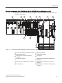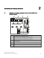
1
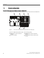
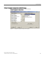
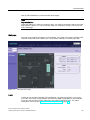
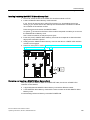
Functions
10.3 Switching power modules off and on during operation
10.3
Switching power modules off and on during operation
What happens when power modules are switched off during operation
If the load power voltage to a power module is switched off during operation, the following
activities take place:
● If you enable diagnostics when assigning parameters for the power module, the
diagnostics interrupt OB 82 (diagnostics address of the power module) is called with the
corresponding diagnostics buffer entry (event ID 3942H).
● The power module is entered as present but faulty in the system status list.
Switching off the load power supply has the following effects on the modules supplied by the
power module:
● The SF LED on the modules lights up.
● The modules can continue to be accessed without an I/O access error occurring.
● The outputs of the modules are deenergized and inactive for the process.
● The inputs of digital modules and FM modules return 0; the inputs of analog modules
return 7FFFH.
What happens when power modules are switched on during operation
If the load power supply to a power module is switched on during operation, the following
activities take place:
● If you enable diagnostics when assigning parameters for the power module, the
diagnostics interrupt OB 82 (diagnostics address of the power module) is called with the
corresponding diagnostics buffer entry (event ID 3842H).
● The power module is entered as present and o.k. in the system status list.
Switching on the load power supply has the following effects on modules supplied by the
power module:
● The SF LED on the modules goes out.
● The modules regain their full functionality.
Removal and insertion of power modules during operation
If, during operation, you remove or insert a power module, the activities listed in section
Removing and inserting modules during operation take place.
Removal and insertion has the same effects as switching the load power supply off and on
for the modules that are supplied by the power module.
Special considerations when using I/O transfer areas
Information on the behavior within the IO controller and the I device during processing,
diagnostics, insert/remove module interrupts and load voltage diagnostics of modules, that
are configured in the I/O transfer area of an I device can be found in the PROFINET System
Description (http://support.automation.siemens.com/WW/view/en/19292127), section
Diagnostics and interrupt behavior and Conditions for use of I devices.
198
IM 151-8 PN/DP CPU interface module
Operating Instructions, 06/2010, A5E02049034-02