1
User’s Manual
P/N 071881-001
EasyCoder 3400e
Bar Code Label Printer
®
Intermec Technologies Corporation
6001 36th Avenue West
P.O. Box 4280
Everett, WA 98203-9280
U.S. service and technical support: 1-800-755-5505
U.S. media supplies ordering information: 1-800-227-9947
Canadian service and technical support: 1-800-668-7043
Canadian media supplies ordering information: 1-800-268-6936
Outside U.S. and Canada:
Contact your local Intermec service supplier.
The information contained herein is proprietary and is provided solely for the purpose of allowing customers
to operate and/or service Intermec manufactured equipment and is not to be released, reproduced, or used for
any other purpose without written permission of Intermec.
Information and specifications in this manual are subject to change without notice.
2001 by Intermec Technologies Corporation
All Rights Reserved
The word Intermec, the Intermec logo, JANUS, IRL, TRAKKER, Antares, Adara, Duratherm, EZBuilder,
Precision Print, PrintSet, Virtual Wedge, and CrossBar are trademarks of Intermec Technologies Corporation.
The name Centronics is wholly owned by GENICOM Corporation.
IBM is a registered trademark of International Business Machines Corporation.
Throughout this manual, trademarked names may be used. Rather than put a trademark (® or ) symbol in
every occurrence of a trademarked name, we state that we are using the names only in an editorial fashion, and
to the benefit of the trademark owner, with no intention of infringement.
The software contained in the EasyCoder® 3400e Printer and the accompanying materials are copyrighted.
Unauthorized copying of the software, including software that has been modified, merged, or included with
other software, or the written materials is expressly forbidden without the prior written consent of Intermec.
All right, title, and interest in all copies of this software are and shall at all times remain the sole and exclusive
property of Intermec. Customers may be held legally responsible for any copyright infringement that is caused
or encouraged by their failure to abide by these terms.
Contents
Contents
Before You Begin ix
Warranty Information ix
Safety Summary ix
Warnings and Cautions x
About This Manual xi
Other Intermec Manuals xiii
1
Getting Started
Getting to Know Your Printer 1-3
Preparing the Printer for Installation 1-5
Plugging In the Printer 1-5
Opening the Printer 1-6
Loading Media for Fanfold Printing 1-7
Printing the Hardware Configuration Test Label 1-9
What the Hardware Configuration Test Label Tells You 1-10
If a Hardware Configuration Test Label Does Not Print 1-10
Connecting the Printer to Your System 1-10
Connecting Your Printer to a PC 1-11
Connecting the Printer to a PC Serial Port 1-11
Connecting the Printer to a PC Parallel Port 1-12
Connecting Your Printer to a Network 1-12
Connecting the Printer to an AS/400 1-13
Connecting the Printer to a Mainframe 1-14
Cabling in Noisy Electrical Environments 1-14
Configuring the Serial Port for Communications 1-15
Verifying Printer Communications With Your System 1-17
2
Operating the Printer
Learning How to Operate the Printer 2-3
Understanding the Front Panel 2-3
Understanding the Front Panel LEDs 2-4
Using the Feed/Pause Button 2-5
iii
EasyCoder 3400e Bar Code Label Printer User’s Manual
Loading Media Into the Printer 2-6
Loading Roll Media for Straight-Through Printing 2-6
Loading Media for Self-Strip Printing 2-8
Loading Thermal Transfer Ribbon 2-10
Setting the Media Sensitivity Number 2-12
Setting the MSN for Intermec Media and Ribbon 2-13
Setting the MSN for Other Media and Ribbon 2-14
Communicating With the Printer 2-16
Using the PrintSet Software 2-16
Using Third-Party Software 2-16
Using Intermec Printer Language (IPL) Commands 2-16
Printing a Test Label 2-17
3
Maintaining the Printer
Inspecting the Printer 3-3
Tools for Cleaning the Printer 3-3
Maintenance Schedule 3-4
Cleaning the Printhead 3-6
Cleaning the Printer Covers 3-7
Cleaning the Drive Roller and Tear Bar 3-8
Cleaning the Media Guides and Media Path 3-9
Cleaning the Label Sensors 3-10
4
Troubleshooting
Troubleshooting Checklist 4-3
Printer Operation Problems 4-3
Print Quality Problems 4-5
Communication Problems and Preventing Data Loss 4-7
5
Optimizing Printer Performance
Optimizing and Maintaining Print Quality 5-3
Correcting Uneven Print Quality 5-3
Adjusting the Print Darkness 5-5
iv
Contents
Adjusting the Label Mark Sensor 5-6
Using the Printer Memory Efficiently 5-8
How Is the Printer Storage Memory Used? 5-8
Making the Most of Your Memory 5-8
Increasing Throughput 5-9
What Is an Image Band? 5-9
How the Image Bands Command Works 5-9
Optimizing Print Speed and Image Band Setting 5-10
6
Using Test and Service Mode
Using Test and Service Mode Procedures 6-3
Printing Test Labels 6-5
Using Data Line Print 6-5
Resetting the Memory on Your Printer 6-6
Setting Configuration Commands in Test and Service Mode 6-6
Setting the Number of Dot Increments 6-7
Adjusting the Label Rest Point 6-9
Setting Emulation Mode 6-11
Using Forms Adjust 6-12
X Forms Adjust 6-13
Y Forms Adjust 6-14
A
Specifications
Printer Specifications A-3
Electrical Requirements A-3
Printing Method A-3
Environment A-3
Self-Strip (optional) A-3
Communications A-3
Specifications A-3
Dimensions (no options installed) A-3
Printhead A-4
Ribbon A-4
Printing Speed A-4
Fonts and Graphics A-4
Character Sets A-4
Media A-5
v
EasyCoder 3400e Bar Code Label Printer User’s Manual
Printer Options A-6
Communication Interface A-6
EasyLAN 10i Interface A-6
Twinax Interface A-6
Coax Interface A-6
Finishers A-6
Cutter A-6
Batch Takeup A-6
Self-Strip Printing A-6
Bar Code Symbologies Supported A-8
2D Symbologies A-9
2D Stacked Symbologies A-9
2D Matrix Symbologies A-9
B
Character Sets
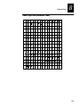
International Character Sets B-3
Advanced Character Table B-3
Emulation Mode Character Table B-4
IBM Translation Character Table B-4
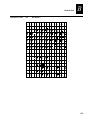
Code Page 850 Character Table B-5
Extended Character Sets B-6
C
Communications Reference
Communication Protocols C-3
Intermec Standard Protocol C-3
XON/XOFF Protocol (Software and Hardware Flow Control) C-4
XON/XOFF, No Status Protocol C-5
Polling Mode D C-5
Multi-Drop Protocol C-5
User-Defined Protocol C-5
Host Requirements C-7
Communications Boundaries C-7
Communications Interfaces
RS-232 Serial Interface
RS-422 Serial Interface
RS-485 Serial Interface
Printer Serial Port C-11
vi
C-7
C-7
C-8
C-8
Contents
D
Full ASCII Table
Full ASCII Table D-3
Full ASCII Control Characters Table D-5
G
I
Glossary
Index
vii
asdf
Before You Begin
Before You Begin
This section introduces you to standard warranty provisions, safety precautions,
warnings and cautions, document formatting conventions, and sources of additional
product information. A documentation roadmap is also provided to guide you in finding
the appropriate information.
Warranty Information
To receive a copy of the standard warranty provision for this product, contact your local
Intermec sales organization. In the U.S. call 1-800-755-5505, and in Canada call 1-800668-7043. Otherwise, refer to the Worldwide Sales & Service list that was shipped with
this manual for the address and telephone number of your Intermec sales organization.
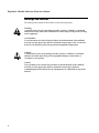
Safety Summary
Your safety is extremely important. Read and follow all warnings and cautions in this
book before handling and operating Intermec equipment. You can be seriously injured,
and equipment and data can be damaged if you do not follow the safety warnings and
cautions.
Do not repair or adjust alone Do not repair or adjust energized equipment alone
under any circumstances. Someone capable of providing first aid must always be
present for your safety.
First aid Always obtain first aid or medical attention immediately after an injury.
Never neglect an injury, no matter how slight it seems.
Resuscitation Begin resuscitation immediately if someone is injured and stops
breathing. Any delay could result in death. To work on or near high voltage, you should
be familiar with approved industrial first aid methods.
Energized equipment Never work on energized equipment unless authorized by a
responsible authority. Energized electrical equipment is dangerous. Electrical shock
from energized equipment can cause death. If you must perform authorized emergency
work on energized equipment, be sure that you comply strictly with approved safety
regulations.
ix
EasyCoder® 3400e Bar Code Label Printer User’s Manual
Warnings and Cautions
The warnings and cautions in this manual use the following format.
Warning
A warning warns you of an operating procedure, practice, condition, or statement
that must be strictly observed to avoid death or serious injury to the persons working
on the equipment.
Avertissement
Un avertissement vous alerte d’une procédure de fonctionnement, d’une méthode,
d’un état ou d’un rapport qui doit être strictement respecté pour éviter l’occurrence
de mort ou de blessures graves aux personnes manupulant l’équipement.
Caution
A caution alerts you to an operating procedure, practice, condition, or statement
that must be strictly observed to prevent equipment damage or destruction, or
corruption, or loss of data.
Conseil
Une précaution vous avertit d’une procédure de fonctionnement, d’une méthode,
d’un état ou d’un rapport qui doit être strictement respecté pour empêcher
l’endommagement ou la destruction de l’équipement, ou l’altération ou la perte de
données.
x
Before You Begin
About This Manual
Analysts and programmers should use this manual to learn how to operate, program,
and connect the EasyCoder® 3400e printer to a network or system. The first part of this
manual tells you how to install, operate, maintain, and troubleshoot your printer. The
last part of the manual covers advanced features of the 3400e printer. A basic
understanding of DOS, programming, and data communications is necessary.
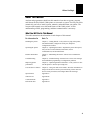
What You Will Find in This Manual
This table summarizes the information in each chapter of this manual:
For Information On
Refer To
Installing the printer
Chapter 1, “Getting Started.” Tells you how to plug in the printer,
load fanfold media, configure the serial port, and print a
configuration test label.
Operating the printer
Chapter 2, “Operating the Printer.” Explains the printer front panel,
tells you how to load roll media, load ribbon, test for
communications, and download fonts.
Routine maintenance
Chapter 3, “Maintaining the Printer.” Shows how to maintain the
printer.
Troubleshooting
Chapter 4, “Troubleshooting.” Instructs how to clear error messages
and troubleshoot programming or configuration problems.
Improving printer
performance
Chapter 5, “Optimizing Printer Performance.” Tells you how to finetune the printer to increase processing time.
Test and Service features
Chapter 6, “Using Test and Service Mode.” Provides information on
using Test and Service mode to print test labels, perform Test and
Service mode procedures, and configure DIP switch settings.
Specifications
Appendix A.
Character sets
Appendix B.
Communications
Appendix C.
Full ASCII chart
Appendix D.
xi
EasyCoder® 3400e Bar Code Label Printer User’s Manual
Terms and Conventions
Listed below are special terms and conventions used throughout the manual. Refer to
the glossary for a complete list of terms found in this manual.
Terms
“Printer” refers to a 3400e bar code label printer.
“Media” is the label stock on which the printer prints labels.
“Host” refers to a personal computer or other computer that communicates with the
printer.
A “symbol” or “bar code symbol” consists of alphanumeric characters encoded in a bar
code format.
Conventions
The following conventions are used throughout this manual for operating procedures
and descriptions of the printer.
•
Feed/Pause refers to the Feed/Pause button on the printer front panel.
•
Downloaded commands appear in the order that you enter them into the printer
with the following conventions:
Convention
<>
data
[data]
xii
Description
Angle brackets < > enclose mnemonic representations of ASCII control
characters. For example, <ETX> represents the ASCII “End of Text” control
character.
Italic text represents variable data, which you must replace with a real value. For
example, n signifies a variable for which you must designate a constant value.
Italic text within brackets represents optional data.
Ctrl
Bold text represents a key on your keypad. For example, Tab represents the Tab
key and M represents the letter M key.
Ctrl-Z
When two keys are joined with a dash, press them simultaneously. For example,
if you see the command Ctrl-C, press the two keys at the same time.
E3;F3
Type all characters that appear in the Courier font by pressing an individual key
on the keypad.
Before You Begin
Other Intermec Manuals
You may need additional information when working with printers in a data collection
system. Please visit our Web site at www.intermec.com to download many of our
current manuals in PDF format. To order printed versions of the Intermec manuals,
contact your local Intermec representative or distributor.
xiii
asdf
1
Getting Started
asdf
HelvC NugFont
C
Getting Started
39
1
This chapter introduces the EasyCoder® 3400e printer and explains how to get your
new printer running for the first time.
Getting to Know Your Printer
Features of your printer include:
•
Support for direct thermal and thermal transfer printing applications. Chapters 1
and 2 explain how to load both types of media.
•
An internal optional self-strip with integral liner takeup. See Chapter 2, “Operating
the Printer,” for more information.
•
An easy-to-use software application called PrintSet. PrintSet makes configuring
your printer, downloading fonts and graphics, and printing a test label effortless.
•
Minimal supervision and maintenance.
•
Support for user-supplied fonts. You can easily download and print user-supplied
fonts. See the PrintSet software application or the IPL Programming Reference
Manual (Part No. 066396) for more information.
•
Support for TrueType. You can easily download and print TrueType fonts. See the
PrintSet software application or the IPL Programming Reference Manual for more
information.
•
e series—IEEE 1284 parallel port. Up to 8 ips (inches per second) print speed with
selected media.
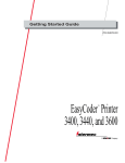
Use the following figures to familiarize yourself with your printer.
1-3
EasyCoder 3400e Bar Code Label Printer User’s Manual
Front View
Media
window
Power/Data
LED
Alert LED
Po
Empty/Pause
button
Ale
Em
Fe
Feed/Pause
button
ed
we
r/D
Media
cover
ata
rt
pty
/P
Inte
/P
au
au
se
se
rme
34
c
00
Media access
door
3XXXU.002
Back View
Darkness adjust
control
DIP switches
1 2 3 4 5 6 7 8
Optional I/O
board port
1 2 3 4 5 6 7 8
Serial communications
port
On/Off
switch
AC power cord
receptacle
Parallel
port
I
O
Media
window
Media
cover
3XXXU.003
Fanfold media
access slot
Several options are available for use with your printer. See Appendix A for complete
descriptions of these options.
1-4
HelvC NugFont
C
Getting Started
39
1
Preparing the Printer for Installation
Before connecting your printer to your data collection system, you need to
•
Plug in the printer.
•
Open the printer and load media.
•
Print a configuration test label.
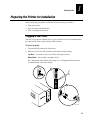
Plugging In the Printer
The back of your printer contains the AC power receptacle, the serial communications
port, the On/Off switch, and two banks of DIP switches.
To plug in the printer
1. Turn the On/Off switch to the off position.
2. Make sure you set the DIP switches to their factory default settings.
Top Bank
Set switch 1 on (I). Set switches 2 through 8 off (O).
Bottom Bank
Set switches 1 through 8 off (O).
For a description of the DIP switch settings, see “Configuring the Serial Port for
Communications” later in this chapter.
1
1
2
2
3
I
4
I
O
5
O
6
7
8
1
2
3
4
5
I
O
6
3
7
8
I
1 2 3 4 5 6 7 8
O
1 2 3 4 5 6 7 8
I
O
3XXXU.004
1-5
EasyCoder 3400e Bar Code Label Printer User’s Manual
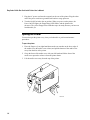
3. Plug the AC power cord into the receptacle at the rear of the printer. Plug the other
end of the power cord into a grounded wall outlet or surge protector.
4. Turn the On/Off switch to the on position. When you power on the printer, the
Power On LED lights, the Empty/Pause LED flashes, and the platen roller
advances. The yellow Empty/Pause LED then stays on steady because you have not
loaded media yet.
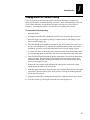
Opening the Printer
You need to open the printer every time you load media or perform maintenance
procedures.
To open the printer
1. Place the fingers of your right hand between the two notches on the lower edge of
the media cover (the media cover release) and pull the bottom of the media cover
away from the base of the printer.
2. Grasp the front of the media cover with your left hand and lift the front of the
media cover upward to release it from the printer frame.
3. Lift the media cover away from the top of the printer.
3
2
Pow
er
/D
Ale
rt
ata
Em
pty
/P
au
se
Fe
ed
/P
au
se
Inte
rmme
ecc
34
00
1
3XXXU.005
1-6
HelvC NugFont
C
Getting Started
39
1
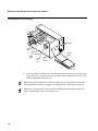
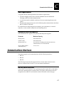
Loading Media for Fanfold Printing
Use the sample of fanfold media provided in the Media Envelope to complete the
following procedures. In fanfold printing, you place a stack of fanfold media at the rear
of the printer and feed it into the printer through a slot in the rear cover. Refer to
Chapter 2, “Operating the Printer,” for instructions on loading rolls of media.
To load media for fanfold printing
1. Open the printer.
2. Disengage the printhead by rotating the head lift lever clockwise until it releases.
3. Move the supply roll retainer by turning it counterclockwise and sliding it to the
outer end of the supply post.
4. Place the fanfold media slightly lower than the slot in the printer back cover. Line
the (box of) fanfold media up with the label path through the printer. Insert media
through the slot at the rear of the printer and thread it over the supply roll post.
5. To allow easy access to the media path, pull down on the lower media guide. Make
sure that the edge guide is slid all the way to the outer edge of the edge guide plate.
6. Insert the fanfold media through the printer mechanism as shown in the illustration
on the next page. The front edge of the media should pass over the tear bar and
through the label dispense opening in the media cover. The fanfold media should
pass over the supply roll post.
7. Release the lower media guide and adjust the edge guide to position the media
firmly against the inside wall of the printer.
8. Slide the supply roll retainer up to the edge of the fanfold media and turn the supply
roll retainer clockwise until it locks firmly in place securing the media against the
inside wall of the printer.
9. Engage the printhead by rotating the head lift lever counterclockwise until it locks.
10. Close the printer by reversing the directions for removing the cover.
1-7
EasyCoder 3400e Bar Code Label Printer User’s Manual
Loading Media for Fanfold Printing
➤
1 2 3 4 5 6 7 8
➤
➤
Media access
slot
➤
Head lift
lever
I
O
Lower
media guide
Edge
guide
1 2 3 4 5 6 7 8
➤
Supply
roll
post
Fanfold
media
Supply
roll
retainer
3XXXU.006
11. Press Feed/Pause to advance one label through the printer and out the label opening
in the front cover. The printer is now ready to print the configuration test label. The
yellow Empty/Pause LED goes out.
Note: If the yellow Empty/Pause LED does not go out, press Feed/Pause a second time
and then reload the media and try again if the Empty/Pause LED still does not go out.
Note: For your convenience, refer to the label with directions for loading media. This
label is located on the inside of the media cover.
1-8
HelvC NugFont
C
Getting Started
39
1
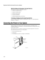
Printing the Hardware Configuration Test Label
You can print the hardware configuration test label to test the printer and make sure it is
operating correctly. The hardware configuration test label lists the printer’s
configuration. Use this label for reference when installing your printer and for
verification of proper printer operation.
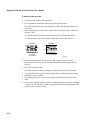
To print the hardware configuration test label
1. Turn the On/Off switch to the off position.
2. Press and hold the Feed/Pause button while you turn the On/Off switch to the on
position. The Alert and Empty/Pause LEDs blink during the printer self-test.
3. Release the Feed/Pause button when the media starts moving. The printer feeds out
one or two blank labels and then prints the hardware configuration test label.
4. Turn the printer power off and then on. You are now ready to connect your 3400e
printer to your system.
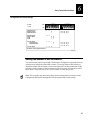
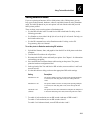
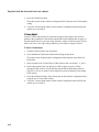
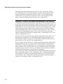
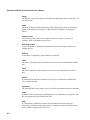
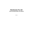
Hardware Configuration Test Label
3400e400 Hardware Configuration
Memory Installed
Flash Storage
Image RAM
Flash SIMM
Mileage
Inches Processed
Inches Burned
Labels Cut
Printhead
Width
Dot Size
Burn Pot Setting
Hardware Options
I/O Option
Internal Option
External Option
Firmware Checksum
ROM0 (U21)
ROM1 (U9)
Program
Version
: 128 kilobytes
: 805 kilobytes
: OKB
:0
:0
:0
: 1792
: 2.5
: 141
: none
: none
: Cutter
:
:
:
:
95D0
7331
067097
2.0
3XXXU.007
Note: This is only an example of a hardware configuration label. Your label may not be
exactly the same.
1-9
EasyCoder 3400e Bar Code Label Printer User’s Manual
What the Hardware Configuration Test Label Tells You
The hardware test label provides these statistics:
•
Amount of installed memory
•
Amount of media printed
•
Printhead configuration
•
Firmware information
•
Printhead alignment (the vertical lines)
If a Hardware Configuration Test Label Does Not Print
If you are unable to print a hardware configuration test label, see “Printer Operation
Problems” in Chapter 4.
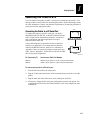
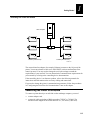
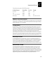
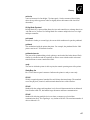
Connecting the Printer to Your System
You can connect your printer to a PC, a local area network, an AS/400 (or other
midrange computer), or a mainframe. This section tells you how to connect your printer
to any of these systems.
This illustration shows you where to connect your system to the printer. You can use
any of these three ports on the rear of the printer:
•
Serial communications port
•
Parallel port
•
I/O board port (if you have an adapter card installed)
Optional I/O
board port
1 2 3 4 5 6 7 8
Parallel port
1 2 3 4 5 6 7 8
I
Serial
communications
port
O
3XXXU.008
1-10
HelvC NugFont
C
Getting Started
39
1
Connecting Your Printer to a PC
You can connect your printer to either a serial port or parallel port on your PC. You
must provide the correct cables for connecting the printer. See the following sections
for cable information. Contact your Intermec representative for ordering assistance if
you do not have the appropriate cables.
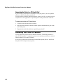
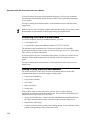
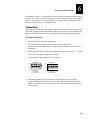
Connecting the Printer to a PC Serial Port
PC
To connect the printer to your PC serial port, you need a
shielded EIA RS-232, RS-422, or RS-485 electrical interface
with a 25-pin D-style subminiature connector. It must have
pins on the printer end and an appropriate serial port
connector on the other end.
Use the following table to determine the correct Intermec
cable for your application. You cannot order an Intermec
cable for the RS-422 interface, but there is a schematic in
Appendix C that you can use to purchase or make your own
cable. Also see Appendix C for the RS-232, RS-422, and RS485 serial port pin assignments.
Printer
For Connecting To
Use Intermec Cable Part Number
IBM PC
048668 (25-pin printer to 25-pin serial port null modem)
IBM PC
048693 (25-pin printer to 9-pin serial port null modem)
3XXXU.009
To connect your printer to a PC serial port
1. Turn the On/Off switch to the off position.
2. Plug the 25-pin connector into the serial communications port on the rear of the
printer.
3. Plug the other end of the cable into a serial (COM) port on the PC.
4. If necessary, change the PC serial port configuration to match your printer. See
“Configuring the Serial Port for Communications” later in this chapter for more
information.
1-11
EasyCoder 3400e Bar Code Label Printer User’s Manual
Connecting the Printer to a PC Parallel Port
If you are using a parallel port to communicate with your printer, you need a parallel
cable to run between the printer and the PC.
You can purchase a parallel cable from Intermec (Part No. 051211) or from your local
computer store. See Appendix A for pin descriptions of the parallel cable connector.
To connect your printer to a PC parallel port
1. Turn the On/Off switch to the off position.
2. Plug the parallel interface connector into the parallel communications port on the
rear of the printer.
3. Plug the other end of the cable into a parallel port on the PC.
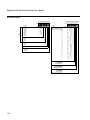
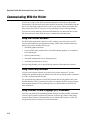
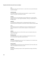
Connecting Your Printer to a Network
You can connect the printer to Novell NetWare networks, Token Ring networks, or
other TCP/IP networks. To connect the printer to a network, you must have a network
interface adapter (for example, Ethernet).
A field service technician can install the field installable option (Part No. 056830) in
the optional I/O board port of your printer.
1-12
HelvC NugFont
C
Getting Started
39
1
Connecting Your Printer to a Network
Host computer
Server
Printers (end devices)
Printers (end devices)
3XXXU.019
The network interface adapter (for example, Ethernet) connects to the 10i port of the
printer. Your network must be able to use XON/XOFF (software and hardware flow
control) protocol. You may need to change the serial port settings to match the
requirements of your network. You can determine the communications requirements for
your network by referring to the controlling device documentation.
If the controlling device is an Intermec product, refer to the following manuals for
instructions and information on the necessary cabling and connections.
If you need to change the printer’s communications parameters, follow the procedures
in “Configuring the Serial Port for Communications” later in this chapter.
Connecting the Printer to an AS/400
To connect a printer directly to an AS/400 or other midrange computer, you need
•
a twinax adapter card.
•
a twinaxial cable equivalent to IBM part number 7362267 or 7362062. The
maximum cable length for the twinax interface is 1,525 meters (5,000 feet).
1-13
EasyCoder 3400e Bar Code Label Printer User’s Manual
If you did not have the twinax card installed at the factory, a field service technician
can install the field installable option (Part No. 056835) in the optional I/O board port
of your printer.
For help on cabling and communications, see the manual that comes with the twinax
adapter card.
Note: If you are using a midrange computer other than the AS/400, refer to your system
documentation for information on cabling and setting up communications.
Connecting the Printer to a Mainframe
To connect the printer directly to an IBM mainframe, you need
•
a coax adapter card.
•
a coaxial cable equivalent to IBM part number 2577672 or 1833108.
The maximum cable length allowed is 1,500 meters (4,920 feet). See the IBM
specification Installation and Assembly of Coaxial Cable and Accessories, part number
GA27-2805-4, for further information.
If you did not have the coax card installed at the factory, a field service technician can
install the field installable option (Part No. 056836) in the I/O board port of your
printer.
For help on cabling and communications, see the manual that comes with your coax
adapter card.
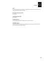
Cabling in Noisy Electrical Environments
The items listed below create noisy electrical environments that can disrupt data
communications between your host computer and the printer:
•
Large power transformers
•
Large electrical motors
•
Arc welders
•
Motor controllers
•
Switch gears
If any of these items are near your printer, you may want to try the following
suggestions to reduce the effects of electrical noise. If you need help eliminating noise,
ask your Intermec representative for assistance.
1-14
•
Always use shielded cable. Connect the cable and shield to the metal backshells on
the cable connectors and fasten the connectors to the serial ports using screws.
•
Install ferrite cable clamps.
•
Connect the printer chassis ground to the building ground. You will find the chassis
ground on the ground pin of the printer power cord.
HelvC NugFont
C
Getting Started
39
1
Configuring the Serial Port for Communications
You need to configure the serial port of the printer to match the configuration of your
PC or network controlling device. If the printer’s default settings do not match, use the
DIP switch settings table to configure the serial port.
To configure the printer serial port
1. Use the following DIP switch setting descriptions and table to locate the DIP
switches you need to change to configure the serial port.
2. Use a small straight-slot screwdriver to set the appropriate DIP switches.
For example, if you want to change the media type to thermal transfer, set DIP
switch 8 on the bottom bank of switches to the on position.
3. Turn the printer power off and then on for the configuration changes to take effect.
Note: Ignore Multi-Drop switches if you are not using a Multi-Drop network.
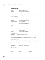
DIP Switch Setting Descriptions
Parameter
Description
Baud rate
The rate, in bits per second, at which the host exchanges data with
the printer. The maximum baud rate is 115,200.
Parity
Adds one bit (1 or 0) to the character to make the sum of bits always
odd or even.
Data bits
The number of bits that represent the ASCII characters.
Stop bits
Timing units between characters that synchronize character
transmission.
Multi-Drop address
Unique address for each device connected with Multi-Drop
protocol.
Protocol
The transmission standards for communication between the printer
and each connecting device.
Media type
Enables the printer to work with either direct thermal or thermal
transfer media.
1-15
EasyCoder 3400e Bar Code Label Printer User’s Manual
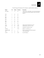
DIP Switch Settings
Bottom Bank Switch Number
Top Bank Switch Number
OFF
Serial I/F
O = OFF
1 = ON
Baud Rate Selection
115200
57600
38400
19200
9600
4800
2400
1200
Parity Selection
*Even
Odd
None
Number of Data Bits
*7 Bit
8 Bit
ON
OFF
1
2
3
4
5
6
7
8
1 1 1
O 1 1
1 O 1
O O O
1 O O
O 1 O
1 1 O
*Indicates Factory Default Setting
ON
Multi-Drop Address Selection
A
B
C
D
E
F
G
H
I
J
K
L
M
N
O
P
Q
R
S
T
U
V
W
X
Y
Z
0
1
2
3
4
5
*
O O
1 O
O 1
O
1
Reserved
Batch Take-Up
*0 Disable
1 Enable
O = OFF
1 = ON
O
1
Protocol Selection
XON/XOFF
Intermec Protocols
*
XON/XOFF Selection
No Status Response
With Status Response
*
Media Type
Direct Thermal
Thermal Transfer
*
Default settings are noted with an *
1-16
1
2
3
4
5
O
1
O
1
O
1
O
1
O
1
O
1
O
1
O
1
O
1
O
1
O
1
O
1
O
1
O
1
O
1
O
1
O
O
1
1
O
O
1
1
O
O
1
1
O
O
1
1
O
O
1
1
O
O
1
1
O
O
1
1
O
O
1
1
O
O
O
O
1
1
1
1
O
O
O
O
1
1
1
1
O
O
O
O
1
1
1
1
O
O
O
O
1
1
1
1
O
O
O
O
O
O
O
O
1
1
1
1
1
1
1
1
O
O
O
O
O
O
O
O
1
1
1
1
1
1
1
1
O
O
O
O
O
O
O
O
O
O
O
O
O
O
O
O
1
1
1
1
1
1
1
1
1
1
1
1
1
1
1
1
6
7
8
O
1
O
1
O
1
3XXXU.020
HelvC NugFont
C
Getting Started
39
1
Verifying Printer Communications With Your System
After connecting the printer to your system, you need to test communications. The
easiest way to test communications is to set the printer to Data Line Print mode, which
is part of Test and Service mode, and send a character string down from your system.
If you have just printed a configuration test label, you are already in Data Line Print
mode. Start the following procedure with Step 4.
To verify communications with your system
1. Turn the On/Off switch to the off position.
2. Press and hold the Feed/Pause button while you turn the On/Off switch to the on
position. The printer prints the hardware configuration test label.
3. Release the Feed/Pause button. You are now in Data Line Print mode.
4. Transmit at least four characters from your system.
At this point, the printer does not attempt to interpret any printer commands, but
simply prints each character with its hexadecimal equivalent underneath.
Note: An example of using DOS to verify printer communications follows this
procedure.
5. To enter normal Print mode, turn the printer power off and then on again.
If this procedure does not work, make sure that the DIP switches match the serial port
configuration of the system and that you have the printer cable securely plugged into
the correct port of your system.
If you receive a write fault error, your cabling may not be correct. See “Connecting the
Printer to Your System” earlier in this chapter for more information.
Note: Please refer to your host computer user's manual and the IPL Programming
Reference Manual for information on downloading commands.
1-17
EasyCoder 3400e Bar Code Label Printer User’s Manual
Example of Using DOS to Verify Printer Communications
1. At the DOS prompt, type this command and press Enter:
MODE COM1 96,E,7,1,N
2. Type these command lines and press Enter:
COPY CON COM1
ABCDEF^Z
where:
COPY CON COM1 has the PC copy the following information to the COM1 port.
ABCDEF are random characters entered at the host.
^Z (Ctrl-Z) Enter sends the information to the printer.
The printer will print these characters:
3XXXU.021
Note: If you are using a different platform to communicate with your printer, please
refer to your host computer user’s manual and the IPL Programming Reference Manual
for help downloading commands.
1-18
2
Operating the Printer
asdf
HelvC NugFont
C
Operating the Printer
39
2
Use this chapter to understand how to use the printer front panel, load roll media and
media for self-strip printing, set the media sensitivity number, and communicate with
the printer.
Learning How to Operate the Printer
To operate the printer, you need to understand:
Front panel Explains how light emitting diodes (LEDs) help you monitor the status of
the printer and the various tasks the Feed/Pause button performs.
Loading media and ribbon Explains how to load roll media, thermal transfer ribbon,
and the procedure for using the self-strip option.
Media sensitivity numbers
Explain how to optimize print quality and print speed.
Communications with the printer Explains different methods for transferring
information from the host to the printer and from the printer to the host.
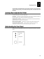
Understanding the Front Panel
Use this section to understand the function of the front panel LEDs and the Feed/Pause
button.
Power/Data
Alert
Empty/Pause
Feed/Pause
3XXXU.024
2-3
EasyCoder 3400e Bar Code Label Printer User’s ManualHelvC
*1233* FG 8pt Italic
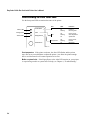
Understanding the Front Panel LEDs
Use the front panel LEDs to monitor the status of the printer:
Green LED
Orange LED
Yellow LED
LED
Power/Data
Power/Data
State
Off
On
Flashing
Indication
Power off
Power on
Receiving data
Alert
Off
Flashing
On
Printing or idle
Over-temperature
System fault
Empty/Pause
Off
Flashing
On
Printing or idle
Paused
Media fault
Alert
Empty/Pause
Feed/Pause
3440U.012
Over-temperature If the printer overheats, the Alert LED flashes and the printer
stops. Do not try to troubleshoot or adjust the printer—just allow the printer enough
time to cool down and it will resume operation on its own.
Media or system faults If the Empty/Pause or the Alert LED remains on, your printer
is experiencing a media or system fault. For help, see Chapter 4, “Troubleshooting.”
2-4
HelvC NugFont
C
Operating the Printer
39
2
Using the Feed/Pause Button
The Feed/Pause button, located on the front of the printer, performs these functions
depending on the mode of the printer:
Printer Mode
You Want To
What to Do
Idle
Feed out one label or a
minimum specified amount
of media.
Press and release the Feed/Pause button.
Continuously feed media.
Press and hold the Feed/Pause button. When
you release the button, the media stops
feeding.
Take the printer offline.
Press the Feed/Pause button twice. Press the
button again to bring the printer online.
Pause the printer.
Press and release the Feed/Pause button.
Press and release the button again to resume
printing.
Cancel the current print
job.
Press and hold the Feed/Pause button until
the printer stops printing.
Print the hardware
configuration label.
Press and hold the Feed/Pause button. See
“Printing the Hardware Configuration Test
Label” in Chapter 1 for more information.
Printing
Powered on for
the first time
2-5
EasyCoder 3400e Bar Code Label Printer User’s ManualHelvC
*1233* FG 8pt Italic
Loading Media Into the Printer
You can load media into the printer in three different ways:
•
Straight-through printing with roll media
•
Self-strip printing with roll media (optional)
•
Fanfold printing (see Chapter 1)
You can load media with the printer power turned on or off. The following procedures
for loading media assume that you have turned the printer on.
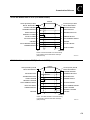
Loading Roll Media for Straight-Through Printing
In straight-through printing, you load a roll of media on the supply roll post and feed it
straight through the printer mechanism and out the front of the printer. As the printer
completes the printing of individual labels, you can remove them from the roll by
pulling them down across the tear bar.
Note: This procedure covers how to load media for straight-through print mode using a
roll of direct thermal or thermal transfer label media. The default setting for the printer
is direct thermal mode; use PrintSet to change the printer to thermal transfer mode.
Note: You should find a small label with a three-digit sensitivity number printed on it
attached to your roll of media or a 15-digit number stamped on the side of the media
roll (Intermec media only). Save this information. You will need it to set the correct
media sensitivity number. See “Setting the Media Sensitivity Number” later in this
chapter for help.
To load the media
1. Raise the printhead by rotating the head lift lever clockwise until the printhead
disengages.
2. Turn the supply roll retainer counterclockwise to release it and then slide it to the
outer end of the supply roll post.
Note: If you are replacing the empty media roll with a new roll of the same width,
you do not need to adjust the edge guide or the supply roll retainer.
3. Place the media roll on the supply roll post and position it firmly against the printer.
Note: If you are using a narrow roll of media [less than 7.62 centimeters (3 inches)],
insert the media support between the roll of media and the supply roll retainer before
securing it.
2-6
HelvC NugFont
C
2
Operating the Printer
39
Loading Roll Media for Straight-Through Printing
Upper
media guide
Head lift
lever
Media
Media roll
Media
backing
Supply roll
post
Supply roll
retainer
Media
support
Edge
guide
Lower
media guide
3XXXU.026
4. Slide the supply roll retainer up to the edge of the media roll and turn the supply
roll retainer clockwise to secure.
5. Pull down on the lower media guide to allow easy access to the media path. Make
sure that the edge guide slides all the way to the outer edge of the lower media
guide.
6. Insert the label stock through the printer mechanism as shown. Make sure the label
passes between the upper and lower media guides. The front edge of the media
should pass over the tear bar and out the front of the printer.
7. Release the lower media guide and adjust the edge guide to position the media
firmly against the inside wall of the printer.
Note: If you are using thermal transfer media, refer to “Loading Thermal Transfer
Ribbon” later in this chapter before you finish performing this procedure.
8. Lower the printhead by rotating the head lift lever counterclockwise until it locks.
9. Use PrintSet, your third-party software, or the IPL command set to configure the
printer for the kind of media you are using (continuous or mark label). Refer to the
PrintSet online help, your third-party documentation, or the IPL Programming
Reference Manual for help.
10. Press Feed/Pause to advance several inches of media through the printer and out the
label opening in the front cover. Your printer is now ready to print labels.
2-7
EasyCoder 3400e Bar Code Label Printer User’s ManualHelvC
*1233* FG 8pt Italic
Note: Refer to the label located on the inside of the media cover for directions on
loading media. For your convenience, you may want to refer to it when loading media
in the future.
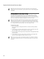
Loading Media for Self-Strip Printing
Use self-strip printing in applications where you want to apply labels to a surface
immediately. After printing a label, the printer prints out the label with the backing
removed. The rewinder hub collects the backing after it passes over the self-strip assist
roller. The rewinder hub can hold the backing from an entire roll of media.
Note: You should find a small label with a three-digit sensitivity number printed on it
attached to your roll of media or a 15-digit number stamped on the side of the media
roll. Save this information. You will need it to set the correct media sensitivity number.
See “Setting the Media Sensitivity Number” later in this chapter for help.
To load self-strip media
1. Raise the printhead by rotating the head lift lever clockwise until the printhead
disengages.
2. Turn the supply roll retainer counterclockwise to release it and slide it to the outer
end of the supply roll post. Turn it clockwise to lock it in place.
3. Place the media roll on the supply roll post and position it firmly against the inside
wall of the printer.
4. Turn the supply roll retainer counterclockwise and slide it up to the edge of the
media roll. Turn the supply roll retainer clockwise to secure.
Note: If you are using a narrow roll of media [less than 7.62 centimeters (3 inches)],
insert the media support between the roll of media and the supply roll retainer before
securing it.
2-8
HelvC NugFont
C
Operating the Printer
39
2
Loading Media for Self-Strip Printing
Media roll
Po
we
r/D
ata
rt
Em
Fe
ed
pty
/P
Inte
/P
au
au
Supply roll
retainer
Supply roll
post
➤
Ale
se
se
Media
support
rm
34 ec
00
➤
➤
➤
➤
➤
Media
liner
Lower media
guide
Upper
media
guide
Edge
guide
Media
access door
Self-strip
assist roller
Rewinder
hub
Rewinder
clasp
Head lift
lever
3XXXU.027
5. Unscrew the edge guide and slide it to the outer edge of the lower media guide.
Screw it in place.
Note: If you are replacing the empty media roll with a new roll of the same width,
you do not need to adjust the edge guide.
6. Pull down on the lower media guide to allow easy access to the media path.
7. Unroll several inches of media, insert it between the upper media guide and the
lower media guide, and out the front of the printer.
8. Release the lower media guide and adjust the edge guide to position the media
firmly against the inside wall of the printer.
9. Pull out 25.4 to 30.48 centimeters (10 to 12 inches) of media and remove the
exposed labels from the media liner.
10. Open the media access door and thread the media liner under the self-strip assist
roller and over the rewinder hub in a clockwise direction.
11. Remove the clasp from the rewinder hub and wind approximately 5.08 centimeters
(2 inches) of media liner clockwise over the rewinder hub.
2-9
EasyCoder 3400e Bar Code Label Printer User’s ManualHelvC
*1233* FG 8pt Italic
12. Secure the media to the rewinder hub by snapping the rewinder clasp onto the
rewinder hub. Turn the rewinder hub clockwise to remove all slack from the media
liner between the tear bar and the rewinder hub.
13. Close the media access door.
14. Rotate the head lift lever counterclockwise until it locks.
15. Use PrintSet, your third-party software, or the IPL command set to enable self-strip
and the label taken sensor. Refer to the PrintSet online help, your third-party
documentation, or the IPL Programming Reference Manual for help.
16. Press the Feed/Pause button to advance a label through the printer. Grasp the
leading edge of the label where it has separated from the backing and pull it away
from the printer.
17. Replace the printer cover. The printer is now ready to print labels.
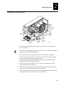
Loading Thermal Transfer Ribbon
If you plan to use thermal transfer mode, you must install a thermal transfer ribbon
(TTR) to print in thermal transfer mode.
Note: Save the packaging that your ribbon came in. Attached to the ribbon packaging is
a small label with a three-digit sensitivity number printed on it (Intermec ribbon only).
You need this information to set the correct media sensitivity number. Refer to the next
section “Setting the Media Sensitivity Number” for more information.
To load thermal transfer ribbon
1. Raise the printhead by rotating the head lift lever clockwise until the printhead
disengages.
2. Place the empty ribbon core that came with the printer onto the ribbon rewind hub.
3. Detach the leader from the new thermal transfer ribbon roll and unwind the end of
the ribbon approximately 20.32 centimeters (8 inches). The edge of the ribbon has a
leader (with an adhesive strip on the leader edge) for guiding the ribbon through the
printhead mechanism.
4. Slide the roll of thermal transfer ribbon onto the ribbon supply hub with the ribbon
roll winding clockwise.
2-10
HelvC NugFont
C
Operating the Printer
39
2
Loading Thermal Transfer Ribbon
Thermal transfer
ribbon
Po
Empty ribbon
hub
we
r/D
ata
Ale
rt
Em
pty
/P
au
se
Fe
ed
/P
au
se
Inte
rme
34
c
00
TTR assist
roller
Printhead
Ribbon supply
hub
Upper media
guide
Ribbon rewind
hub
Head
3XXXU.028
lift lever
5. Route the ribbon leader through the printer mechanism as shown in the above
illustration.
Note: Make sure the ribbon runs above the upper media guide. The shiny side of
the ribbon must come in contact with the printhead.
6. Attach the leader from the new thermal transfer ribbon roll to the empty ribbon core
using the adhesive strip on the leader edge.
7. Wind the ribbon rewind hub clockwise until the ribbon runs smoothly through the
printhead mechanism and the leader moves past the printhead.
8. Rotate the head lift lever counterclockwise until it locks.
9. Enable thermal transfer printing by setting DIP switch 8 on the bottom bank of
switches to the on position. For help, see “Configuring the Serial Port for
Communications” in Chapter 1.
10. Press the Feed/Pause button to advance the ribbon through the printer.
11. Close the printer. The printer is now ready to print.
Note: When replacing the thermal transfer ribbon roll in the future, use the empty
ribbon supply core as the new rewinder core.
2-11
EasyCoder 3400e Bar Code Label Printer User’s ManualHelvC
*1233* FG 8pt Italic
Setting the Media Sensitivity Number
Media sensitivity is important because you use it to optimize print quality and print
speed. The three-digit media sensitivity number (MSN) specifies the amount of heat
required by the printhead to image a label. The amount of heat that each roll of media
or ribbon requires is unique due to different chemistries and manufacturing processes.
Intermec has developed heating schedules (the amount of heat required to image a
label) to produce the highest possible print quality for Intermec media and ribbon
combinations on Intermec printers.
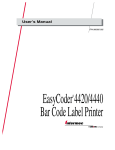
Look for the three-digit media sensitivity number on
•
the side of the media roll. Use the last three digits (140 in the example) of the
15-digit number stamped on the roll for the media sensitivity number.
•
a small label attached to the roll of media.
•
a small label attached to the plastic bag of your ribbon roll. Your label may be
different than this example, but it will contain the sensitivity number.
120066102605140
SENSITIVITY NUMBER
120066102605140
5✩7
3XXXU.029
Note: Some ribbon rolls have the media sensitivity number printed on the inside core.
Use this three-digit number to optimize print quality and print speed on your printer.
You can achieve the best print quality on the printer by using only Intermec ribbon and
media products. The default sensitivity setting for thermal transfer media is 567. For
direct thermal media, the default sensitivity setting is 470.
Use the PrintSet software, your third-party software, or the IPL command set to change
the media sensitivity number. If you want to see the current sensitivity setting of your
printer, print out a software configuration label.
2-12
HelvC NugFont
C
Operating the Printer
39
2
To print a software configuration label
1. Turn the On/Off switch to the off position.
2. Press and hold the Feed/Pause button while turning the printer on. The printer
prints out a hardware configuration label.
3. Set the DIP switches to print out the software test label.
Top Bank
Set switches 1 through 6 and 8 off. Set switch 7 on.
Bottom Bank
Set switches 1 through 8 off.
4. Hold the Feed/Pause button down for 1 second. The printer prints out the software
configuration label.
5. Return the DIP switches to their original settings.
6. Turn the printer power off and then on.
Setting the MSN for Intermec Media and Ribbon
For direct thermal media, use the three-digit sensitivity number located on the roll of
media to set the sensitivity number. You can also use the values from the tables in the
next section.
For thermal transfer media, you need to look in two places to determine the sensitivity
number. The sensitivity number on each roll of thermal transfer media or ribbon has an
asterisk (*) in place of one of the digits. On thermal transfer media, the rating contains
the first and second digits, with an asterisk in place of the third digit. The number on
the ribbon has the first and third digits, with an asterisk in place of the second digit.
To optimize the sensitivity number for thermal transfer media, you combine the digits
as in this example.
Media or Ribbon
Sensitivity
Number
Thermal transfer media
56*
The asterisk reserves the third digit to identify
the ribbon’s sensitivity number.
Thermal transfer ribbon
5*7
The asterisk reserves the second digit to identify
the media’s sensitivity number.
567
Optimized sensitivity number
Description
2-13
EasyCoder 3400e Bar Code Label Printer User’s ManualHelvC
*1233* FG 8pt Italic
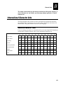
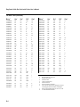
Setting the MSN for Other Media and Ribbon
If you are not using Intermec media and ribbon, or you misplaced your packaging with
the three-digit sensitivity number label on it, you can set the approximate sensitivity
number. The first column of the Direct Thermal and Thermal Transfer Media
Sensitivity Settings tables list the approximate sensitivity settings. To achieve
acceptable print quality, enter the three-digit media sensitivity number (for example,
800).
If you are unsure of how to set the media sensitivity number, start with the highest
setting, which provides the lowest energy (800 for thermal transfer and 700 for direct
thermal), and work your way down until you achieve the best print quality. You can
also use PrintSet’s Print Quality Wizard to help achieve print quality.
3400e Printer Direct Thermal Media Sensitivity Settings
Approximate
Sensitivity Numbers
Sensitivity
Setting
Direct Thermal Media
Maximum
Recommended
Print Speed
700 Series High Sensitivity
720
Duratherm Lightning Plus - 2
8
400 Series Medium
Sensitivity
480
Duratherm Lightning IR Tag
5
470
460
450
440
420
Duratherm Lightning - 1
European IR
Duratherm Lightning IR Labels - 1
European Thermal
Duratherm Lightning Labels - 1
5
5
5
5
5
100 Series Low Sensitivity
180
170
160
140
130
Duratherm II - 1
European Tag
Duratherm II Tag
European Top
Duratherm II - 2
3
3
3
3
3
800 Series High Sensitivity
(Paper)
864
European Uncoated/Standard - 1
8
854
834
Duratran TTR Paper Labels/Standard - 1
Duratran TTR Paper Tags/Standard - 1
6
6
687
Duratran TTR Polyester 1/Premium - 7
6
677
633
627
623
Duratran Syntran/Premium - 7
European Polyethelene/Premium
Duratran Kimdura/Premium - 7
Duratran Kimdura/Premium
6
8
8
6
600 Series Medium
Sensitivity (Paper)
2-14
HelvC NugFont
C
Operating the Printer
39
2
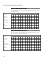
3400e Printer Thermal Transfer Media and Ribbon Sensitivity Settings (continued)
Approximate Sensitivity
Numbers
Sensitivity
Setting
Direct Thermal Media
Maximum
Recommended
Print Speed
500 Series Medium
Sensitivity (Paper)
567
Duratran II-1/Premium - 7
8
565
European Premium Paper/Premium
4
563
Duratran II-1/Premium
7
533
European Tag/Premium
6
527
Duratran II Tag - 7 mil/Premium - 7
6
513
European Coated/Premium
6
369
Super Premium Poly./Super Premium - 3
5
366
Super Premium Poly./Super Premium - 7
5
238
Gloss Polyimide (Kapton)/Gloss Super Premium
3
236
226
222
Gloss Polyimide (Kapton)/Super Premium-7
Matte Polyimide (Kapton)/Super Premium-7
Matte Polyimide (Kapton)/Matte Super Premium
3
3
3
300 Series Low Sensitivity
(Plastic)
200 Series Low Sensitivity
(Kapton)
2-15
EasyCoder 3400e Bar Code Label Printer User’s ManualHelvC
*1233* FG 8pt Italic
Communicating With the Printer
You are now ready to print labels by downloading data from the host to the printer.
Downloading is the universal term used to describe the transfer of information from the
host to any connected peripheral device, such as your printer. When you transfer data
from your printer to the PC or host, you are performing a process called uploading.
You can use several methods to download information in your data collection system.
The next sections describe different ways to communicate with the printer.
Using the PrintSet Software
Use the PrintSet application software to easily configure your printer from your PC.
You can upload the current configuration settings, modify them, and then download
them to your printer. PrintSet also lets you
•
download graphics and fonts.
•
print test labels using resident fonts, user-defined bitmap graphics, or resident bar
code symbologies.
•
allocate printer memory.
•
download configuration files to multiple printers.
•
use flash-based firmware (e series).
For help using PrintSet, refer to the online help portion of the application software.
Using Third-Party Software
You can use third-party software to set many of the printer parameters. You can
configure the parameters that your software does not set by using the printer command
set or the configuration DIP switches.
Use your third-party software to create label formats and convert graphics into a userdefined character (UDC) format that the printer can interpret. Refer to your third-party
documentation and the IPL Programming Reference Manual (Part No. 066396) for
more information.
Using Intermec Printer Language (IPL) Commands
You can create labels by downloading formats (designs) and data with IPL commands.
You can use the printer to perform any function or activate any feature of the printer
except for those features or functions that you set with the DIP switches. See the IPL
Programming Reference Manual for more information.
2-16
HelvC NugFont
C
Operating the Printer
39
2
Printing a Test Label
If you would like to test your communications by downloading a label, follow the
example below. Use the PrintSet application software to send a test label to the printer.
This example assumes that your printer is communicating with a PC and that the printer
is correctly loaded with media.
To print the test label
1. Start PrintSet on your PC.
2. From the Options menu, choose Test Print.
3. Select the Test Label option button.
4. Select either the Text or the Bar Code option button.
If you select to print text, you can choose any font in the Select Printer Font list
box.
If you select to print a bar code, you can choose any symbology in the Select
Symbology list box.
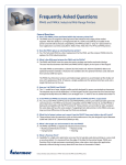
5. Choose Print. Your attached printer prints a test label.
For example, if you chose to print a bar code with the Code 39 symbology, your
printer prints a label similar to this one:
*0123456789*
*0123456789*
*0123456789*
*0123456789*
3XXXU.030
2-17
adf
3
Maintaining the Printer
asdf
HelvC NugFont
C
Maintaining the Printer
39
3
This chapter contains cleaning procedures and a schedule detailing how often to
perform maintenance procedures. Even though the design of your printer enables it to
withstand harsh environments, you must clean it on a regular basis to keep it running
at its highest performance level.
It is very important to perform the maintenance procedures if you expose the printer
to dirt or debris. For information on maintenance procedures such as replacing media
or ribbon, see Chapter 1, “Getting Started,” and Chapter 2, “Operating the Printer.”
Inspecting the Printer
Inspect the printer and the rest of your data collection system equipment on a regular
basis. Your inspection should include the following:
•
Make sure you have properly grounded the printer.
•
Inspect the work environment. Large electric motors, welders, and switching
equipment can affect printer performance.
•
Keep the printer away from liquids.
•
Check the data collection network regularly for loose wires or poorly installed
connections. Be sure to replace corroded wires.
Tools for Cleaning the Printer
To clean the printer safely and effectively, use the following items:
•
Isopropyl alcohol
•
Cotton swabs
•
Clean lint-free cloth
•
Vacuum cleaner
•
Soapy water/mild detergent
•
Printhead cleaning pad (Part Number 1-110501-00)
The following procedures explain how to access the printer parts and clean them
without causing any harm to the printer or yourself.
3-3
EasyCoder 3400e Bar Code Label Printer User’s ManualHelvC NugFont
C
39
Maintenance Schedule
Clean your printer regularly to maintain the quality of your labels and extend the life of
your printer. This table contains suggestions for cleaning the printer. Use the
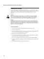
illustration on the next page to locate the parts you need to clean.
Printer Component
Maintenance Period
Printhead
Inspect after every roll of media or ribbon. Clean after
every roll [or 15,240 centimeters (6,000 inches)] of
media or more often if necessary.
Printer Cover
Clean as necessary.
Drive roller and tear bar
Clean after every five rolls of media. If you are using hitack adhesive, you must clean after every roll of media.
If you are using tag stock or continuous media, you may
want to clean after every five rolls of media or as
necessary. Clean more often in environments that are
harsh or dusty.
Media path (not shown)
Edge guide
Upper media guide
Lower media guide
Thermal transfer ribbon (TTR) assist
roller
Self-strip roller
Label gap sensor (not shown)
Label mark sensor (not shown)
Label taken sensor
Pinch roller
3-4
HelvC NugFont
C
Maintaining the Printer
39
3
Locating the Printer Parts You Need to Maintain
TTR assist
roller
Po
Ale
Em
Fe
Label taken
sensor
ed
we
r/D
ata
rt
pty
/P
au
/P
au
Inte
se
se
rme
c
34
00
Tear bar
Upper media
guide
Drive
roller
Pinch
roller
Thermal
Self-strip printhead
roller
Lower media
Edge guide
guide
3XXXU.032
Warning
Switch off the printer power and remove the power cord before cleaning any part of
the printer.
Avertissement
Mettez l’imprimante hors tension et débranchez le câble d’alimentation avant de
nettoyer une parte de l’imprimante.
3-5
EasyCoder 3400e Bar Code Label Printer User’s ManualHelvC NugFont
C
39
Cleaning the Printhead
In order for the printhead to provide good print quality, it must maintain close contact
with the media. Therefore, cleaning media debris from the printhead is very important.
Clean after every roll [or 15,240 centimeters (6,000 inches)] of media or when
necessary.
Caution
Do not use sharp objects such as knives or screwdrivers to scrape the printhead
clean. Cleaning with sharp objects will damage the printhead. Clean with only a
cotton swab, or a clean, lint-free cloth or tissue damp with isopropyl alcohol.
Conseil
N’utilisez pas d’objets pointus tels que couteaux ou tournevis pour nettoyer la tête
d’imprimante. Nettoyer avec des objets pointus endommagera la tête d’imprimante.
Nettoyez-la seulement avec de la ouate ou avec un linge propre et libre de peluches,
humecté avec de l’alcool d’isopropyl.
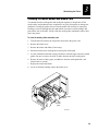
To clean the printhead
1. Turn the On/Off switch to the off position and remove the power cord.
2. Remove the media cover.
3. Rotate the head lift lever clockwise until the printhead releases. Rotating the head
lift lever raises the printhead to allow for cleaning.
4. Remove the media and ribbon (if necessary).
5. Use a cotton swab moistened with alcohol to remove any dirt, adhesive, or debris
from the print surface on the bottom of the printhead.
6. Wait 5 to 10 seconds for the print surface to dry. Replace the media and ribbon.
7. Engage the printhead by rotating the head lift lever counterclockwise until it locks
in place.
8. If you are finished cleaning, replace the media cover.
3-6
HelvC NugFont
C
Maintaining the Printer
39
3
Cleaning the Printhead
Ribbon
supply
hub
Ribbon
rewind
hub
Supply
roll
post
Po
we
r/D
ata
rt
Ale
Em
pty
/P
au
se
Fe
e
d/P
au
se
InInte
terrmm
eec
3 c
40
0
Head
lift
lever
Printhead
3XXXU.033
Cleaning the Printer Covers
Use a general purpose cleaner (soapy water/mild detergent) to clean the printer covers.
Do not use abrasive cleansers or solvents. Be sure to clean the transparent panel on the
media cover so that the media supply inside the printer is visible when you close the
cover.
3-7
EasyCoder 3400e Bar Code Label Printer User’s ManualHelvC NugFont
C
39
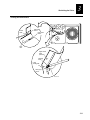
Cleaning the Drive Roller and Tear Bar
Cleaning the drive roller and tear bar preserves print quality by maintaining close
contact between the media and the printhead.
To clean the drive roller and tear bar
1. Turn the On/Off switch to the off position and remove the power cord.
2. Remove the media cover.
3. Rotate the head lift lever clockwise to release the printhead.
4. Remove the media and ribbon (if necessary).
5. Clean the drive roller by using a cloth dampened with isopropyl alcohol. Move the
cloth over the drive roller in a side-to-side motion as shown. Make sure to rotate the
roller so that you can clean all areas.
Note: Rotating the TTR assist roller toward you enables you to clean the entire
drive roller surface.
6. Clean both sides of the tear bar with a cloth dampened with isopropyl alcohol.
Remove all traces of dust, paper, and adhesive.
7. Replace the media and ribbon.
8. Engage the printhead by turning the head lift lever counterclockwise until the
printhead locks.
9. If you are finished cleaning, replace the media cover.
TTR assist
roller
Po
we
r/D
ata
Ale
rt
Em
pty
/P
au
se
Fe
ed
/P
au
se
Inte
A
Lit
rme
ton
Co
34
mp
c
an
y
00
Head lift
lever
Tear
bar
3-8
Drive
roller
3XXXU.034
HelvC NugFont
C
Maintaining the Printer
39
3
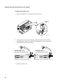
Cleaning the Media Guides and Media Path
You should clean the media guides and media path regularly to keep debris off the
media surface and printhead where irregularities can spoil print quality or damage the
printhead. Cleaning the guides also prevents the media from skewing or improperly
tracking as it travels through the paper path which can result in smeared images and
print off the side of the label. Always clean the media guides immediately after a label
jam in the printer.
To clean the media guides and media path
1. Turn the On/Off switch to the off position and remove the power cord.
2. Remove the media cover.
3. Remove the media and ribbon (if necessary).
4. Pull down on the lower media guide to open up the media path.
5. Use the cloth moistened with isopropyl alcohol to clean the upper and lower media
guides. Be sure to remove all traces of debris. Release the lower media guide.
6. Remove all traces of dust, paper, and adhesive from the media path with a soft
bristle brush or vacuum.
7. Replace the media and ribbon.
8. If you are finished cleaning, replace the media cover.
Po
we
r/D
Ale
rt
ata
Em
pty
/P
au
se
Fe
ed
/P
au
se
Inte
rme
34
c
00
Upper media
guide
Lower
media
guide
Media
path
3XXXU.035
3-9
EasyCoder 3400e Bar Code Label Printer User’s ManualHelvC NugFont
C
39
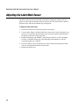
Cleaning the Label Sensors
Three label sensors on the printer require regular cleaning:
•
Label taken sensor
•
Label mark sensor
•
Label gap sensor
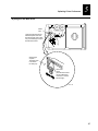
To clean the label sensors
1. Turn the On/Off switch to the off position and remove the power cord.
2. Remove the media cover.
3. Rotate the head lift lever clockwise to release the printhead. Rotating the head lift
lever raises the printhead to allow access to the label mark sensor.
4. Remove the media and ribbon (if necessary).
5. Clean the label taken sensor with a cotton swab moistened with isopropyl alcohol.
6. Pull down on the lower media guide to expose the label gap sensor. Using a
cleaning brush or vacuum, remove all debris and dust from the label gap sensor.
7. Clean the label gap sensor with a cotton swab and alcohol.
8. Replace the media and ribbon.
9. Engage the printhead by rotating the head lift lever counterclockwise until it locks
in place.
10. Replace the media cover.
3-10
HelvC NugFont
C
Maintaining the Printer
39
3
Cleaning the Label Sensors
Cotton
swab
Label taken
sensor
Label mark
sensor
Drive
roller
Upper media
guide
(underside)
Cleaning
brush
Lower
media guide
Label gap
sensor
3XXXU.036
3-11
NugFont
asdf
C
39
4
Troubleshooting
asdf
HelvC NugFont
C
Troubleshooting
39
4
This chapter provides some hints for troubleshooting error messages that the printer
sends to the host and problems you may experience with the printer.
Troubleshooting Checklist
Even though Intermec designed your printer to operate under harsh conditions, you may
still encounter a printer operation, print quality, or communication problem at some
time. You can easily fix most of the errors you encounter and consequently not delay
operation of the printer for very long.
To troubleshoot your printer
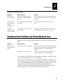
1. First try cleaning the printer components and checking all of the connections. See
Chapter 3, “Maintaining the Printer,” for details.
2. If cleaning the printer and checking the connections does not solve the problem, use
the following tables to locate the symptom. Follow the solution in the table to fix
your problem.
If you receive an error message, refer to the IPL Programming Reference Manual
(Intermec Part No. 066396) for a complete list of error messages and their solutions.
If the problem persists, contact your Intermec Customer Service Representative (1-800755-5505) from North America. If you are an international customer, contact your local
Intermec representative.
Printer Operation Problems
If your printer is not operating correctly, try locating the problem in the table below:
Symptom
Possible Causes
Solution
No power or loss of
power.
You have damaged or disconnected
the AC power cable.
Make sure you have plugged the power cable into
both the printer and an outlet or power strip. Replace
the cable if damaged.
Printer circuit breaker tripped.
Turn the printer off, then back on again.
Printer is out of media.
Load new media. Refer to Chapter 1, “Getting
Started,” or Chapter 2, “Operating the Printer.”
You have loaded the label stock
incorrectly.
Check the media path. See Chapter 1, “Getting
Started,” or Chapter 2, ”Operating the Printer.”
Labels stop feeding
through the printer.
4-3
EasyCoder 3400e Bar Code Label Printer User’s ManualHelvC NugFont
C
39
Printer Operation Problems (continued)
Symptom
Possible Causes
Solution
Labels stop feeding
through the printer.
(continued)
You have set the printer for
continuous label stock.
Use PrintSet to check the configuration settings. If
the settings are incorrect, use PrintSet to change the
settings.
Media is sticking to the paper path.
Clean any extraneous material from the paper path
and clean the path thoroughly. Refer to Chapter 3,
“Maintaining the Printer.”
You have incorrectly set the image
bands or print speed.
Use PrintSet to change the image bands or print
speed settings.
Printer has aborted and reset the
print speed and image bands.
Use PrintSet to change the image bands or print
speed settings.
Labels stick to door
or fail to strip.
The self-strip roller is dirty.
Clean the self-strip roller. See Chapter 3,
“Maintaining the Printer.”
The Alert LED
flashes and printing
stops.
Printhead has overheated.
Leave printer alone until it has time to cool down. It
will resume printing on its own.
Media fault.
The printhead is up.
Make sure the printhead is down. The head lift lever
should be straight up and down. Press the Feed/Pause
button to resume printing.
Sensor type set incorrectly.
Configure the printer for the correct sensor for the
Print mode you are using. You can enable self-strip
and other Print modes from PrintSet.
You have incorrectly loaded the
media.
Try reloading the media. For help, see “Loading
Media Into the Printer” in Chapter 2.
You have incorrectly loaded the
media.
Try reloading the media. For help, see “Loading
Media Into the Printer” in Chapter 2.
You have configured the printer for
self-strip media.
Set the printer to the default configuration using the
DIP switches. For help, see “Plugging In the Printer”
in Chapter 1.
Media fault.
Remove media from under the label taken sensor.
Printer slows down.
Test configuration
label does not print.
4-4
HelvC NugFont
C
Troubleshooting
39
4
Printer Operation Problems (continued)
Symptom
Possible Causes
Solution
Printer is not
communicating, not
printing, or not
printing properly.
Corrupt or incorrect information in
printer memory.
Reset the memory to return the printer to its default
configuration. For help, see “Resetting the Memory
on Your Printer” in Chapter 6. After you reset the
memory, power off the printer and return the DIP
switches to the required setting. For help, see
“Configuring the Serial Port for Communications” in
Chapter 1.
Print Quality Problems
If your labels are not printing properly, check the following table to locate the symptom
and correct the problem.
Symptom
Possible Causes
Solution
Blotches printing on
labels.
Dirty printhead.
Clean the printhead. For help, see “Cleaning the
Printhead” in Chapter 3.
Dirty media path or rollers.
Clean the media path. For help, see “Cleaning the
Media Guides and Media Path” in Chapter 3.
Poor quality label or ribbon stock.
Use only Intermec label and ribbon stock to ensure
superior print quality and product performance.
Incorrect media sensitivity setting.
Change sensitivity setting to match the type of media
you are using (for help, see “Setting the Media
Sensitivity Number” in Chapter 2). If you set the
sensitivity setting correctly, try changing the dark
adjust.
Incorrect darkness adjust control
setting.
Adjust the knob to achieve the best print quality. For
help, see “Adjusting the Print Darkness” in Chapter 5.
Poor quality label or ribbon stock.
Use only Intermec label and ribbon stock to ensure
superior print quality and product performance.
Dirty printhead.
Clean the printhead. For help, see “Cleaning the
Printhead” in Chapter 3.
Printing is too light
or too dark.
4-5
EasyCoder 3400e Bar Code Label Printer User’s ManualHelvC NugFont
C
39
Print Quality Problems (continued)
Symptom
Possible Causes
Solution
Printing not aligned
on label.
Printer is misfeeding media.
Make sure you have correctly installed the media. For
help, see “Loading Media Into the Printer” in Chapter
2.
Labels are not
stopping at the right
point for removal.
Incorrect label rest point setting.
Adjust the label rest point. For help, see your PrintSet
online help or the IPL Programming Reference
Manual.
Incorrect label stock setting.
Set the printer to thermal transfer or direct thermal
label stock. For help, see “Loading Media Into the
Printer” in Chapter 2.
Incorrect media sensitivity setting.
Change sensitivity setting to match the type of media
you are using. If you set the sensitivity setting
incorrectly, try changing the print darkness. For help,
see your PrintSet online help or the IPL
Programming Reference Manual.
Incorrect darkness control setting.
Adjust the darkness adjust control. For help, see
“Adjusting the Print Darkness” in Chapter 5.
Print speed exceeds the capability of
the media.
Lower your print speed or use Intermec media
recommended for your print speed.
Printhead, platen roller, or label path
are dirty.
Clean printhead, platen roller, and label path as
described in Chapter 3, “Maintaining the Printer.”
Uneven print contrast (density).
Adjust the bias adjust screw. See “Correcting Uneven
Print Quality” in Chapter 5.
Poor quality label or ribbon stock.
Use only Intermec label and ribbon stock to ensure
superior print quality and product performance.
Ribbon wrinkling.
Check to make sure that you installed the ribbon
correctly. For help, see “Loading Thermal Transfer
Ribbon” in Chapter 2. Set the bias adjust screw. See
“Correcting Uneven Print Quality” in Chapter 5.
Ribbon installed upside down.
Install ribbon with shiny side facing the printhead.
See “Loading Thermal Transfer Ribbon” in Chapter
2.
Direct thermal/thermal transfer
switch set in the wrong position.
Set the switch for the type of media you are using.
For help, see “Loading Media Into the Printer” in
Chapter 2.
Print quality is
poor.
4-6
HelvC NugFont
C
Troubleshooting
39
4
Print Quality Problems (continued)
Symptom
Possible Causes
Solution
Print quality is
poor. (continued)
Media may be slipping against the
platen roller causing the printing to
compress.
Switch to approved media or clean the printhead and
platen roller as described in Chapter 3, “Maintaining
the Printer.”
The printer skips
labels randomly or
sends an
intermittent error.
The label format extends beyond the
label length.
Edit the format to ensure that the text fits on the
label.
Continuous
empty/pause fault
light (yellow LED).
The label mark sensor is not in the
correct position.
Properly position the label mark sensor. For help, see
“Adjusting the Label Mark Sensor” in Chapter 5.
Communication Problems and Preventing Data Loss
If your printer is not receiving downloaded data, try the solutions in the accompanying
table.
Symptom
Possible Causes
Solution
Printer does not
communicate with
the host.
Serial port is incorrectly configured.
Make sure the printer’s serial port settings match those
of the host. Print a software test configuration label as
described in Chapter 1 to check the serial port
settings.
Damaged or incorrect I/O cable.
Check the connections at both ends or replace the
cable. See Appendix C for cable information.
Several problems can cause data loss or communication problems on the printer. Data
loss can result in printing errors or missing field data.
Your printer is a serial ASCII device. It communicates with the host through an ASCII
serial communication I/O port. Hardware handshaking involves the use of a hardware
wire. Software handshaking involves a two-way datalink between the devices. The two
devices communicate with each other without losing data through the use of
handshaking. The printer sends both forms of handshaking simultaneously when the
printer’s input buffer is full. Any loss of data can cause printing errors.
4-7
EasyCoder 3400e Bar Code Label Printer User’s ManualHelvC NugFont
C
39
Hardware handshaking uses pin 11 or pin 20 of the RS-232 interface to control data
flow. When the printer is using Intermec Standard protocol, it holds pins 11 and 20 high
when the printer is ready to receive data. The printer holds the pins low when the
printer is in one of the following conditions:
•
Buffer full
•
Ribbon fault
•
No label stock
•
Label at strip bar
Your printer uses XON/XOFF protocol for software handshaking. When the input
buffer is full, the printer transmits an XOFF character. The XOFF character alerts the
host to the fact that the printer buffer is full and cannot receive any more data. When
the printer is ready to receive more data, it sends the XON character.
The following procedure lists things to check to ensure that your printer and host
system are communicating properly.
To check for communication problems
1. Check the cabling from the printer to the host system.
2. Check the interfacing of the devices that are communicating with the printer.
3. Check the printer for proper electrical operation of the I/O port.
4. Test to see that the host system is not overrunning the printer'’s input buffers.
5. Check to see that the data string being sent to the printer contains the correct
information.
4-8
5
Optimizing Printer Performance
asdf
HelvC NugFont
C
Optimizing Printer Performance
39
5
This chapter explains how to optimize and maintain print quality, use the printer
memory more efficiently, and maximize throughput.
Optimizing and Maintaining Print Quality
Intermec designed and configured your printer to provide the best possible print quality
for both direct thermal and thermal transfer media. However, there are many factors
that you need to take into account before you can achieve maximum print quality. The
following sections contain information on:
•
Correcting uneven print quality
•
Adjusting the print darkness
•
Adjusting the label mark sensor
•
Using the printer memory efficiently
•
Increasing throughput
Correcting Uneven Print Quality
You may experience problems in print quality (ribbon wrinkling or light print on one
side of your label) if the printhead is not making even contact with the label stock. This
condition can happen with any size label stock, but is most common when using narrow
label stock. You need a straight-slot screwdriver to turn the bias adjust screw.
To achieve the best print quality, adjust the bias adjust screw each time you use media
of a different width.
Note: You must properly adjust the bias adjust screw to prevent premature printhead
failure and excessive platen wear.
5-3
EasyCoder 3400e Bar Code Label Printer User’s ManualHelvC NugFont
C
39
To adjust the bias adjust screw
1. Remove the media cover and locate the bias adjust screw.
Bias adjust
screw
Po
Al
we
er
r
t
Em
pt
Fe
ed
y/
/P
Inte
Pa
au
us
e
se
rmec
34
00
3XXXU.038
2. To compensate for uneven print quality, turn the bias adjust screw as shown.
Adjusting the bias adjust screw causes the printhead to rest evenly on the drive
roller and results in even print quality.
If printing is light on
the left side of label, turn
the bias adjust screw clockwise.
A
R
E
A
R
E
If printing is light on the
right side of label, turn the
bias adjust screw counterclockwise.
3XXXU.039
3. Replace the media cover.
5-4
HelvC NugFont
C
Optimizing Printer Performance
39
5
Adjusting the Print Darkness
Use the darkness adjust control in combination with the PrintSet software configuration
tool to fine-tune the darkness of print on your labels. The fine adjustments compensate
for variations in the media (“lot to lot”), the printhead, or the printer. Set the darkness
adjust control after you enter the media sensitivity number.
To adjust the print darkness
1. Locate the darkness adjust control on the back of the printer.
2. Use a small straight-slot screwdriver to adjust the print darkness.
•
To increase the print darkness, turn the control clockwise.
•
To decrease the print darkness, turn the control counterclockwise.
1 2 3 4 5 6 7 8
Turn the darkness
Darkness
adjust control clockwise adjust control
for darker density
1 2 3 4 5 6 7 8
Turn the darkness adjust
control counterclockwise
for lighter density
I
1 2 3 4 5 6 7 8
O
1 2 3 4 5 6 7 8
Screwdriver
3XXXU.037
5-5
EasyCoder 3400e Bar Code Label Printer User’s ManualHelvC NugFont
C
39
Adjusting the Label Mark Sensor
The label mark sensor detects the mark on the back of continuous media stock. The
printer uses the output to determine the start of print. The label mark sensor is behind
the platen roller and near the inboard edge of the printer.
To adjust the label mark sensor
1. Remove the media cover and locate the label mark sensor.
2. Use your index finger to slide the label mark sensor to the correct position for your
media. You can position the label mark sensor anywhere from the inboard edge of
the printer to the center of the paper path.
3. Enable mark printing with PrintSet, your third-party software, or IPL commands.
For help, see PrintSet online help, your third-party documentation, or the IPL
Programming Reference Manual.
4. Print a few labels or press Feed/Pause two times to make sure that the label mark
sensor is detecting the black mark on the media.
5. Replace the media cover.
5-6
HelvC NugFont
C
Optimizing Printer Performance
39
5
Adjusting the Label Mark Sensor
Platen
roller
Locate the label mark sensor
behind the platen roller near
the inboard edge of the printer.
Use your index finger to adjust
the label mark sensor.
Inboard edge
of printer.
The platen roller
is not shown
for clarity only.
Label mark
sensor
(The label mark sensor
can be positioned no
more than 1" from the
inboard edge.)
3XXXU.040
5-7
EasyCoder 3400e Bar Code Label Printer User’s ManualHelvC NugFont
C
39
Using the Printer Memory Efficiently
To receive the best performance from your printer, you must understand how to use the
printer memory. The following sections can help you determine the most efficient way
to use your printer memory.
How Is the Printer Storage Memory Used?
There is enough storage memory in the printer to store several different label formats
and still retain enough memory to store downloaded fonts, graphics, and data. Be
careful of how you use your printer memory.
The printer uses flash memory for storing tables, pages, formats, fonts, and user-defined
characters (UDCs). The 3400e printer has 128K of flash memory available for storage.
If you require additional storage memory, you can purchase flash SIMM for the printer.
The printer supports these parameters independent of the amount of memory installed
or allocated by the printer:
•
Maximum number of formats: 99
(You can edit formats 1 to 99. You cannot edit default format 0.)
•
Fields per format: 200
•
Maximum data buffer size for a field: 3550
•
Maximum number of UDCs: 100
•
Maximum number of user-defined fonts: 16
Making the Most of Your Memory
There are limits to the number of formats, fonts, graphics, or pages that you can store in
the printer. You can define up to 16 fonts, but there may not be enough room depending
on the amount of memory being used for other purposes. The more formats, graphics,
and fonts you store, the less memory is available.
When you run into a memory usage problem, use PrintSet to see how much memory
remains available. You must upload the memory information from the printer first.
Refer to the PrintSet online help for more information.
5-8
HelvC NugFont
C
Optimizing Printer Performance
39
5
If you find that it is necessary to increase your available memory, you can do one of the
following:
•
Increase the amount of available memory by using the Memory Reset portion of the
Test and Service menu. See “Resetting the Memory on Your Printer” in Chapter 6
for more information.
•
Delete any unneeded user-defined fonts, graphics, pages, or formats. For help, see
the PrintSet software or the IPL Programming Reference Manual.
•
Purchase additional memory. Please contact your Intermec representative for
information on purchasing additional memory for the printer.
Increasing Throughput
To print labels as quickly as possible, you must adjust the print speed in conjunction
with the number of image bands [one image band equals 2.54 centimeters (1 inch) of
label]. The print speed and image band settings determine the rate at which the printer
processes the images of your labels. This rate in turn affects the throughput of the entire
printing process.
The printer begins imaging the label as soon as it receives the command to select a
format. Since the printer starts imaging the label so early, the chance that the imaging
process will be unable to keep up with the print speed decreases and throughput
improves. However, if the number of image bands is too low, the imaging process is
unable to keep up with the print speed. In this case, the printer stops printing and starts
again at the lowest print speed with the maximum number of image bands. If the image
band command is set too high, the printer spends more time than necessary imaging and
slows down label production.
What Is an Image Band?
Image bands are a section of memory where a picture of a label format is drawn. This
drawing process is known as imaging. Once the picture is imaged, the printer loads the
picture from the image bands to the printhead for printing. Each image band is equal to
2.54 centimeters (1 inch) of length of the label format. The number of image bands you
use may be less than the length of the label you are printing. The number of image
bands (in inches) does not have to equal the length of the label since the printer recycles
the image bands. Once the contents of an image band have been printed, it may be
reused to image the next section of the label.
Keep in mind that the more complex the label, the longer it will take to image each
section, thus requiring a slower print speed. To use a higher print speed, use more
image bands to allow more of the imaging process to complete before printing begins.
How the Image Bands Command Works
The image bands command controls the amount of memory allotted to the imaging
process. When you increase the image band adjustment to a higher number, you add
more buffers to the imaging memory. By doing this, more of the label format is imaged
before printing begins.
5-9
EasyCoder 3400e Bar Code Label Printer User’s ManualHelvC NugFont
C
39
The minimum number of required image bands is dependent upon the print speed and
the complexity of the label. Labels that contain numerous fields with different rotations,
graphics, or combinations of these formatting options may require a higher number of
image bands.
To set the number of image bands, use PrintSet or the IPL command. For help, see the
PrintSet online help or the IPL Programming Reference Manual.
Optimizing Print Speed and Image Band Setting
The maximum number of image bands available for use is 20 bands. The minimum
number of image bands available is 2.
To optimize the number of image bands for your print speed
1. Set the image band setting at the lowest number (2).
2. Print a label at the desired speed.
If the label prints, the image band setting is optimal. You do not need to perform
any more adjustments.
If the number of image bands is too low, the printer aborts the label before printing
is completed and attempts to reprint the label at the slowest speed (2 ips) with the
highest number of image bands (20). You need to continue with Step 3.
3. Return to the original print speed and increase the original number of image bands
one at a time.
Continue to increase the number of image bands until the printer prints a label
correctly.
If the printer still aborts and reprints at the highest image band setting, you may be
trying to optimize at a print speed that is too high for your label format. Try optimizing
the number of image bands at a lower print speed or add an expansion DRAM SIMM.
To print very complex labels at high speeds, you must allocate enough image bands to
completely image the label before printing. Allocate one band for each inch of label
length. By doing this, you can print at any speed. However, there may be a considerable
delay between labels.
5-10
6
Using Test and Service Mode
asdf
HelvC NugFont
C
Using Test and Service Mode
39
6
This chapter explains the different procedures you can perform while the printer is in
Test and Service mode. Use Test and Service mode on the printer to print test labels,
perform special procedures, and change select configuration commands.
Using Test and Service Mode Procedures
For all Test and Service mode tests, pressing the Feed/Pause button pauses the current
test. Holding the Feed/Pause button aborts the current test and starts a new test.
To enter Test and Service mode
1. Record your current DIP switch settings for later reference.
2. Set all of the DIP switches to the off position.
Set all of the DIP switches to the communications settings of your host computer.
3. Turn the On/Off switch to the off position.
4. Press and hold the Feed/Pause button while turning the power on.
The printer prints out a hardware configuration label and then enters Data Line
Print mode.
5. Set the DIP switches to the test or service function you wish to perform. See the
following table for a list of the DIP switch settings.
6. Hold the Feed/Pause button down. The test begins immediately.
7. If you wish to perform another function, change the DIP switch settings and press
the Feed/Pause button.
The function the printer is currently executing terminates, and the printer performs
the new function.
The printer remains in Test and Service mode until you turn the power off and reset the
DIP switches. The printer executes all functions as soon as you select them.
To exit Test and Service mode
1. Turn the printer power off.
2. Reset the DIP switches to their original settings.
3. Turn the printer power back on.
6-3
EasyCoder 3400e Bar Code Label Printer User’s Manual
Use the information in the following table to set the DIP switches for the appropriate
Test and Service mode function you want to perform.
Test and Service DIP Switch Settings
Default settings are noted with an
*
O = OFF
1 = ON
OFF
TESTS
ON
Top Bank
1
2
3
4
5
6
Bottom Bank
7
8
Test Prints
Configurations
Hardware*
Software
Test Labels
Print Quality
Pitch
Page
Single Page
All Pages
Format
Single Format
All Formats
UDC
Single UDC
All UDCs
Font
Single Font
All Fonts
O O O
Data Line Print
*1
O O O O O O O
Selective Transfer
Receiver
Send Pages
Single Page
All Pages
Send Format
Single Format
All Formats
Send UDC
Single UDC
All UDCs
Send Font
Single Font
All Fonts
Send Configuration
Send Tables
Send All
Memory Reset
Page/Format
UDC/Font
Configuration
Tables
All
1
1
1
2
3
4
5
6
7
8
O O O
1
O
1
O O
1 O
Q
Q
O O
1 O
O O O
Q
Q
O O
1
1
O O
N N N N N
1 1 1 1 1
Q
Q
N N N N N
1 1 1 1 1
Q
Q
O O O
1 O O
N N N N N N N Q
1 1 1 1 1 1 1 Q
1
O
1 O O
N N N N N
1 1 1 1 1
O
O O O
1 O O S
1
O
1
1
1
O O
1 O
O 1
1 1
O O
O S
1
O S
1
1
S
1
S
1
S
1
S
1
S D D D D D
1 1 1 1 1 1
S
1
S
1
S
1
S D D D D D
1 1 1 1 1 1
S
1
S
1
S
1
S S
1 1
S
1
S
1
S
1
S D D D
1 1 1 1
S
1
S
1
1
1
1
1
O O O
1 O O
O 1 O
1 1 O
1 1 1
Q: OFF = Batch of 1. ON = Batch of 100.
N: Page/Format/UDC/Font number. Least significant bit first.
S: Source Page/Format/UDC/Font number. Least significant bit first.
D: Destination Page/Format/UDC/Font number. Least significant bit first.
3XXXU.041
6-4
HelvC NugFont
C
Using Test and Service Mode
39
6
Printing Test Labels
The printer can print a variety of test print labels that provide you with information
about the printer configuration and the quality of the printing.
To print a test label
1. Turn the On/Off switch to the off position.
2. Press and hold the Feed/Pause button while turning on the printer.
The printer prints a hardware configuration label and then enters Data Line Print
mode.
3. Set the DIP switches to print the test label of your choice: software, print quality, or
pitch. Refer to the Test and Service DIP Switch Settings table for the correct
settings.
4. Hold the Feed/Pause button down until the printer starts printing.
The printer begins printing out the test label immediately.
5. Exit Test and Service mode by turning the printer off and returning all DIP
switches to their original settings.
Using Data Line Print
Use Data Line Print mode to troubleshoot communication between the printer and the
host and to test the operation of the printer. When the printer is in Data Line Print
mode, it prints out all downloaded data with the hexadecimal equivalent directly
underneath it. Hold the Feed/Pause button down to momentarily suspend the test. Press
the Feed/Pause button longer to transmit the firmware program and version number to
the host.
To enter Data Line Print mode
1. Turn the On/Off switch to the off position.
2. Press down and hold the Feed/Pause button while turning on the printer.
The hardware configuration test label prints out. You are now in Data Line Print mode.
6-5
EasyCoder 3400e Bar Code Label Printer User’s Manual
Resetting the Memory on Your Printer
Use memory reset if you want to return your printer to its default configuration or if
you need to increase the amount of memory available in your printer. You can also use
memory reset to clear pages and formats, user-defined characters and fonts,
configurations, tables, or all of these parameters.
To use memory reset
1. Turn the printer off.
2. Press and hold the Feed/Pause button while turning on the printer. The printer
prints a hardware configuration test label.
3. Set the DIP switches to reset a portion or all of the memory by using the Test and
Service DIP Switch Settings table on page 6-4.
4. Hold the Feed/Pause button down for 1 second. The printer resets a portion or all of
its memory.
Setting Configuration Commands in Test and Service Mode
Test and Service mode also provides you with an alternative to using PrintSet or
sending configuration commands down from the host. You can change these
configuration commands by setting the Test and Service mode DIP switches:
•
Label rest point
•
86XX emulation
•
X forms adjust
•
Y forms adjust
The following table provides you with the Test and Service mode DIP switch settings
for changing the configuration commands.
6-6
HelvC NugFont
C
Using Test and Service Mode
39
6
Configuration DIP Switch Settings
Top Bank
O = OFF
1 = ON
Bottom Bank
OFF
ON
1
2
3
Label Rest Point
Adjust Forward
Adjust Backward
O
1
1
86XX Emulation
Advance Mode
10 Mil
15 Mil
1
X Forms Adjust
Adjust Forward
Adjust Backward
1
Y Forms Adjust
1
4
5
7
8
1
2
3
4
5
6
7
8
N N N N N
N N N N N
O
1
O
6
1
O O
1 O
1 1
1
1
1
O
1
1
1 O
N N N N N
N N N N N
N N N N N
N: Number. Least significant bit first.
3XXXU.046
Setting the Number of Dot Increments
You can move the label rest point and X forms adjust configuration commands forward
or backward by setting the printer DIP switches. Use the top bank of DIP switches to
determine whether the movement is forward or backward. Use the bottom bank of DIP
switches to set the number of dot increments for label rest point, X forms adjust, and Y
forms adjust. The printer moves in 5 mil increments or 0.005 inch per dot.
Note: The next table only shows the settings for the bottom bank of switches, see the
Configuration DIP Switch Settings table for the top bank DIP switch settings.
6-7
EasyCoder 3400e Bar Code Label Printer User’s Manual
Dot Increments DIP Switch Settings
Bottom Bank
OFF
0 = OFF
1 = ON
ON
1
2
3
4
5
1
O
1
O
1
O
1
O
1
O
1
O
1
O
1
O
1
O
1
O
1
O
1
O
1
O
1
O
1
O
O
1
1
O
O
1
1
O
O
1
1
O
O
1
1
O
O
1
1
O
O
1
1
O
O
1
1
O
O
1
O
O
O
1
1
1
1
O
O
O
O
1
1
1
1
O
O
O
O
1
1
1
1
O
O
O
O
1
1
1
O
O
O
O
O
O
O
1
1
1
1
1
1
1
1
O
O
O
O
O
O
O
O
1
1
1
1
1
1
1
O
O
O
O
O
O
O
O
O
O
O
O
O
O
O
1
1
1
1
1
1
1
1
1
1
1
1
1
1
1
# of dot increments
1
2
3
4
5
6
7
8
9
10
11
12
13
14
15
16
17
18
19
20
21
22
23
24
25
26
27
28
29
30
3XXXU.047
6-8
HelvC NugFont
C
Using Test and Service Mode
39
6
To set the number of dot increments.
1. In the top bank, turn the appropriate switches on or off for forward or backward
movement. See the Configuration DIP Switch Settings table on page 6-7 for the
appropriate DIP switch settings.
2. Go to the Dot Increments DIP Switch Settings table on page 6-8 and scan down the
# of Dot Increments column until you reach the number of dot increments you want
to adjust the command forward or backward.
3. In the bottom bank turn on the switches that have a 1 in their column. Turn off all
other switches.
4. Press the Feed/Pause button and the printer prints the software configuration label
and stops at the new location.
For example, you print a label and discover that it does not extend far enough from the
tear bar. You need to move the label rest point forward 10 dot increments (0.05 inch) so
that the printer feeds more label out when it is done printing. Find 10 in the # of Dot
Increments column. It shows a 1 in the columns of DIP switches 2 and 4, and a O in the
columns of 1, 3, and 5. The 1 tells you to turn the switch on. The O tells you to turn the
switch off. Turn on switches 2 and 4. Turn off all other switches.
Adjusting the Label Rest Point
The label rest point configuration command adjusts the point at which the printer
presents each label for removal. Use this command in conjunction with self-strip
applications. The label rest point adjust range is from -30 dot increments (farthest back)
to +30 dot increments (farthest forward).
Use a negative number if you want the printer to retract the label a number of dot
increments after it prints the label. Use a positive number if you want the printer to feed
the label a number of dot increments after it prints the label.
There are three ways to adjust the label rest point:
•
You can use the Test and Service DIP switch bank. Follow the procedure below to
use the DIP switch settings to adjust the label rest point.
•
You can set it by using the PrintSet application software. See the Paper Handling
portion of PrintSet for more information.
•
You can use the IPL command. See the IPL Programming Reference Manual for
more information.
6-9
EasyCoder 3400e Bar Code Label Printer User’s Manual
To adjust the label rest point
1. Turn the On/Off switch to the off position.
2. Press and hold the Feed/Pause button while turning on the printer.
The printer prints the hardware configuration test label and then enters Data Line
Print mode.
3. In the top bank of the Test and Service DIP switches, turn off switch 1 and turn on
switches 2 and 3.
To adjust the label rest point forward (feed more label), turn off DIP switch 4.
To adjust the label rest point backward (retract label), turn on DIP switch 4.
Top Bank
Top Bank
OFF
OFF
ON
ON
1
2
3
4
Switch settings
for feeding
label forward
1
2
3
4
Switch settings
for retracting label
3XXXU.48
4. In the bottom bank of the Test and Service DIP switches, turn on or off the
appropriate DIP switches. See the Dot Increments DIP Switch Settings table on
page 6-8.
5. Press the Feed/Pause button.
The printer prints the software configuration label and stops at the new location.
6. Verify that the label rest point number on the software configuration label matches
the number you set in Step 4.
7. Try printing again to see if you need to readjust the DIP switches in the bottom
bank.
8. If you need to readjust the DIP switches in the Bottom Bank, repeat Steps 4 through
7. If not, exit Test and Service mode by turning off the printer and returning all DIP
switches to their original settings.
6-10
HelvC NugFont
C
Using Test and Service Mode
39
6
Setting Emulation Mode
If you are replacing an Intermec 8636 or 8646 printer with a 3400e printer, you can
keep your existing network, hardware, software, and label formats by using Emulation
mode. The labels produced on your new printer will look like the ones that your old
86XX printer printed.
There are three ways to set the printer to Emulation mode:
•
Use the DIP switches in the Test and Service DIP switch bank. For help, see the
following procedure.
•
Use PrintSet to select either 100 dpi (10 mil) or 66 dpi (15 mil) mode. For help, see
the PrintSet online help.
•
Use the IPL command set to select Emulation mode. For help, see the IPL
Programming Reference Manual.
To set the printer to Emulation mode using DIP switches
1. Upload label formats, fonts, and graphics from the 8636 or 8646 printer to the host
computer.
2. Turn the On/Off switch to the off position.
3. Disconnect the 86XX printer and install your printer. See Chapter 1 for information
on installing your printer.
4. Press and hold the Feed/Pause button while turning on the printer. The printer
prints the hardware configuration label.
5. In the top bank of the Test and Service DIP switches, turn on switches 1 and 3 and
turn off switch 2.
6. Use the table below to help you choose the appropriate DIP switch settings:
Setting
Description
Emulation 10 mil
The printer emulates an 8636 or 8646 printer printing multiples
of 10 mil (0.01 inch) drag and 10 mil (0.01 inch) picket bar
codes.
Emulation 15 mil
The printer emulates an 8636 or 8646 printer printing multiples
of 10 mil (0.01 inch) drag and 15 mil (0.015 inch) picket bar
codes.
Advanced 5 mil
(default)
The printer uses the 3400 command set and prints in multiples of
5 mil (0.005 inch) drag and 5 mil (0.005 inch) picket bar codes.
7. To enable 10 mil emulation, turn on DIP switch 4 and turn off DIP switch 5.
To enable 15 mil emulation, turn on DIP switches 4 and 5.
To enable 5 mil Advanced mode, turn off DIP switches 4 and 5.
6-11
EasyCoder 3400e Bar Code Label Printer User’s Manual
8. Press the Feed/Pause button.
The printer prints out the software configuration label. Verify that the label states
the correct mode.
9. Turn the printer off and then on.
10. Download the 86XX formats, fonts, and graphics from the host to the printer.
Using Forms Adjust
If your label prints too close to one edge, you can reposition it by using the X Forms
Adjust and Y Forms Adjust features. The X forms adjust controls the position of the
printing area along the length of the label. The Y forms adjust controls the position of
the printing area along the width of the label.
The following figure shows the default X and Y origins. You can control the default X
origin (top of form) with the PrintSet software or with the Test and Service DIP
switches. You can control the default Y origin with the DIP switches only.
Origin (Ø,Ø)
-X➤
Y *FORMAT*
➤ +X
*FORMAT*
➤
+Y
Leading
Edge
3XXXU.049
➤
6-12
Direction of media from printer
HelvC NugFont
C
Using Test and Service Mode
39
6
The default X origin is .25 centimeters (0.10 inch) (20 dot increments) from the edge of
the label. You can move the X origin forward or back 30 dot increments. The default Y
origin is .13 centimeters (0.05 inch) (10 dot increments) from the leading edge of the
label. Each dot increment is 5 mil (0.005 inch).
X Forms Adjust
When you move the X origin forward, the printer moves the top of form away from the
edge before printing the label information. When you move the X origin backward, the
printer moves the top of form closer to the edge before printing the label information.
To set the X forms adjust
1. Turn the On/Off switch to the off position.
2. Press and hold the Feed/Pause button while turning on the printer.
The printer prints out the hardware configuration label and then enters Data Line
Print mode.
3. In the top bank of the Test and Service DIP switches, turn on switches 1, 2, 3, and 4.
To move the X origin forward, turn off switch 5.
To move the X origin backward, turn on switch 5.
Top Bank
Top Bank
OFF
OFF
ON
ON
1
2
3
4
Switch settings
for moving the
X origin forward
5
1
2
3
4
5
Switch settings
for moving the
X origin backward
3XXXU.050
4. In the bottom bank of the Test and Service DIP switches, turn on or off the
appropriate DIP switches. See the Dot Increments DIP Switch Settings table on
page 6-8 to see how to set the X forms adjust forward or backward a given number
of increments.
6-13
EasyCoder 3400e Bar Code Label Printer User’s Manual
5. Press the Feed/Pause button.
The printer prints out the software configuration label using the new X forms adjust
setting.
6. Verify the X forms adjust number on the software configuration label matches the
number you set in Step 4.
Y Forms Adjust
Use the Y Forms Adjust feature to control the position of the image in the direction
parallel to the printhead. See the Dot Increments DIP Switch Settings table on page 6-8
for information on how to move the image forward a number of dot increments. If your
label is too close to one edge of the printhead, you can adjust it using this feature.
To set the Y forms adjust
1. Turn the On/Off switch to the off position.
2. Press and hold the Feed/Pause button while turning on the printer.
The printer prints out the hardware configuration label and then enters Data Line
Print mode.
3. In the top bank of the Test and Service DIP switches, turn on switches 1, 2, and 3.
4. In the bottom bank of the Test and Service DIP switches, turn on or off the
appropriate DIP switches. See the Dot Increments DIP Switch Settings table on
page 6-8 to see how to set the X forms adjust forward or backward a given number
of increments.
5. Press the Feed/Pause button. The printer prints out the software configuration label
using the new Y forms adjust setting.
6. Verify the Y forms adjust number on the software configuration label matches the
number you set in Step 4.
6-14
A
Specifications
asdf
HelvC NugFont
C
Specifications
39
A
Printer Specifications
This section describes the specifications of the 3400e printer.
Electrical Requirements
Input Voltage
Frequency
100, 120, or 230 VAC ± 10%
47-63 Hz
Printing Method
The 3400e printer is capable of direct thermal (DT) printing or thermal transfer (TTR)
printing using thermal transfer ribbon.
Environment
Operating
Humidity
10°C to 40°C (50°F to 104°F)
10% to 90% noncondensing
Self-Strip (optional)
The self-strip rewinder hub can take up the backing of an entire 15,240-centimeter
(6,000-inch) roll of media.
Peel Release
10-50 grams
Note: Self-strip printing is an option that you order with your printer.
Communications
Asynchronous RS-232C, RS-422, RS-485 interfaces
Serial ASCII code
Hardware (Ready/Busy) Flow Control
XON/XOFF Protocol
Intermec Standard Block Protocol
Polling Mode D Protocol
Multi-Drop Protocol
Baud Rates: 1,200, 2,400, 4,800, 9,600, 19,200, 38,400, 57,00, 115,200
Specifications
Dimensions (no options installed)
Height
27.9 cm (11 inches)
Width
26.7 cm (10.5 inches)
Length
43.2 cm (17 inches)
Weight
15.8 kg (35 pounds)
A-3
EasyCoder 3400e Bar Code Label Printer User’s Manual
HelvC NugFont
C
39
Printhead (200 dpi)
Printed dot size
0.127 mm (0.00492 inch square)
Width
104 mm (4.1 inches square)
Resolution
8 dots per mm (203 dots per inch)
Number of elements
832 per printhead
“X” dimensions
10 mil to 50 mil (0.25 mm to 1.27 mm); 5 mil (0.13 mm) in drag
mode only (specified media only)
Printhead (400 dpi)
Printed dot size
0.065 mm (0.0025 inch square)
Width
112 mm (4.4 inches maximum)
Resolution
16 dots per mm (406 dots per inch)
Number of elements
1,792 per printhead
“X” dimensions
5 mil to 50 mil (0.127 mm to 1.27 mm); 2.5 mil (0.06 mm) in drag
mode only (specified media only)
Ribbon
Roll
152 m (6,000 linear inches)
Widths
51 mm (2.0 inches)
76 mm (3.0 inches)
104 mm (4.1 inches)
Diameter
57 mm (2.25 inches maximum)
Printing Speed
Maximum
8 inches (152.4 mm) per second
Minimum
2 inches (50.8 mm) per second
You can change the print speed in 1 ips increments only: 2, 3, 4, 5, 6, 7, or 8.
Fonts and Graphics
There are 21 resident bitmap fonts (including OCR A and B) and three outline fonts
available on the e series printers. You can use font ID 3 through 6 and 8 through 19 to
download user-defined fonts.
Maximum UDF
102 mm square (4 inches square)
Maximum UDC
102 mm square (4 inches square)
Character Sets
A-4
US ASCII
Norwegian/Danish
French
UK ASCII
Swedish/Finnish
Swiss
German
Italian
Spanish
HelvC NugFont
C
Specifications
39
A
Media
C
D
F
E
G
H
A
B
3XXXU.O55
Number
Description
Minimum
Maximum
A
Label width
16.5 mm (0.65 inch)
111.8 mm (4.4 inches)
B
Backing width (or tag width)
19.1 mm (0.75 inch)
114.3 mm (4.5 inches)
C
Gap between labels
2.54 mm (0.10 inch)
25.4 mm (1.0 inch)
D
Label length - self-strip media
25.4 mm (1.0 inch)
609.6 mm (24 inch)
Label length - butt cut media
12.7 mm (0.5 inch)
609.6 mm (24 inch)
E
Media thickness (including backing)
0.15 mm (0.0059 inch)
0.30 mm (0.012 inch)
F
Reflective sensor mark length
2.54 mm (0.10 inch)
12.7 mm (0.5 inch)
G
Notch diameter
3.18 mm (.125 inch)
N/A
H
Notch height
6.4 mm (0.25 inch)
N/A
Roll diameter
N/A
213 mm (8.38 inches)
A-5
EasyCoder 3400e Bar Code Label Printer User’s Manual
HelvC NugFont
C
39
Printer Options
This page contains a list of the options you can use with the printer along with a brief
description. Consult your Intermec representative to order any option.
Communication Interface
EasyLAN 10i Interface
This option lets you connect your printer to a 10bBaseT Ethernet network. Various
network printing protocols are available. For more information, see your EasyLAN 10i
documentation.
Twinax Interface
This option lets you connect your printer to an IBM twinaxial cable system with a
twinax interface so your printer emulates an IBM 5256 Model 1 printer and can operate
with an IBM System/34, System/36, System/38, or AS/400 host computer.
Coax Interface
The coax interface adapter allows the printer to emulate an IBM 3287 printer by
connecting the printer to IBM 3270 Type A coaxial cable computer systems operating
in the VTAM (CICS/IMS/TSO) or 8100 (DPPX) environments. With the coaxial
adapter you can connect the printer to an IBM 3174/76/99 system
controller/multiplexer.
Finishers
Cutter
Use the cutter option to cut continuous media into individual labels ready for use. This
3400 option works best for individual random lengths or short batches of different label
lengths.
Batch Takeup
This device automatically spools labels as they are printed. This attachment is limited
to small batches with maximum outer diameter (OD) of 12.7 centimeters (5 inches).
Self-Strip Printing
Use self-strip printing in applications where you want to apply labels to a surface
immediately. After printing a label, the printer prints out the label with the backing
removed. This option must be ordered when you order your printer.
A-6
HelvC NugFont
C
Specifications
39
A
The following pin descriptions are for the printer’s parallel interface connector:
Signal
Pin
Return
Direction
Description
DATASTB
1
19
IN
Negative pulse. Latches DB0-7 on the rising edge. Eight bits
in parallel provide data input. High is logical 1 and LOW is
logical 0.
DB0
2
20
IN
DB1
3
21
IN
DB2
4
22
IN
DB3
5
23
IN
DB4
6
24
IN
DB5
7
25
IN
DB6
8
26
IN
DB7
9
27
IN
ACK
10
28
OUT
Negative pulse. Data has been received.
BUSY
11
29
OUT
If HIGH, printer cannot receive data.
PE
12
30
OUT
If HIGH, out of ribbon or media.
SELECT
13
-
OUT
Pulled to +5V. Printer is on.
CHASSIS GND
17
-
-
Printer's chassis gnd isolated from logic gnd.
INIT
31
16
IN
Clears I/OINT0 latch.
FAULT
32
33
OUT
See printer display.
A-7
EasyCoder 3400e Bar Code Label Printer User’s Manual
HelvC NugFont
C
39
Bar Code Symbologies Supported
The e series printers support these bar code symbologies:
Codabar Originally developed in 1972, Codabar is a numeric symbology most
commonly used in libraries, blood banks, and air parcel express applications.
Code 2 of 5 Code 2 of 5 is a straightforward numeric symbology developed in the late
1960s. It has been used for warehouse sorting systems, photofinishing envelope
identification, and for tracking sequentially numbered airline tickets. All information is
contained in the width of the bars; the spaces do not contain information.
Code 11 Code 11 was developed in early 1977 to satisfy requirements for a very high
density, discrete numeric bar code. The most extensive application of Code 11 has been
for labeling telecommunications equipment.
Code 39 Code 39 is the first alphanumeric symbology ever developed and is the
standard non-retail bar code. It is a discrete, self-checking symbology of variable length
and is used mostly by the automobile and medical industries.
Code 93 Introduced in 1983, Code 93 was specially designed to complement Code 39.
With the correct reading equipment, the two alphanumeric codes may be interchanged
throughout a system without making any changes to software.
Code 128 Code 128 was introduced in 1981 as a very high density, alphanumeric
symbology. It is a variable length, continuous code that employs multiple element
widths.
EAN The European Article Numbering system (abbreviated as EAN) is a numeric
superset of UPC. EAN has both a version that uses 8 digits and a version that uses 13
digits. The version with 13 digits encodes the same number of bars as 12 digit UPC
Version A, but the 13th digit is encoded into a parity pattern at the left of the center
guard bar.
Interleaved 2 of 5 Interleaved 2 of 5 is a high density, self-checking, continuous
numeric symbology, which has mainly been used in the distribution industry.
Interleaved 2 of 5 actually encodes two digits, one in the bars and one in the spaces.
POSTNET The Postal Numeric Encoding Technique (POSTNET) uses binary digits,
represented as full bars and half bars, to provide a numeric bar code symbology that is
easily read and decoded by optical reading systems. POSTNET provides both error
detection and correction capabilities.
HIBC 128
See the IPL Programming Reference Manual for a complete list.
A-8
HelvC NugFont
C
Specifications
39
A
UPC Universal Product Code (UPC) is a subset of EAN. It is a fixed length, numeric,
continuous symbology employing four element widths. Two common types of UPC are
Version A, which encodes 12 digits, and Version E, which encodes 6 digits. UPC has
been used in the supermarket industry since 1973. UPC supplemental code is intended
for only periodical issue numbers.
2D Symbologies
2D symbologies provide a more efficient way of encoding data than standard bar code
symbologies. 2D symbologies use two dimensions to hold data instead of one, allowing
much more information to be stored in a smaller amount of space. Your printer provides
the capability for printing both stacked and matrix 2D symbologies.
2D Stacked Symbologies
2D stacked symbologies consist of short linear segments stacked on top of each other.
In addition to being able to condense a large amount of information into the stacked
format, PDF417 provides an extensive error detection and correction option. Up to 510
characters can be recovered if they are lost due to an error in scanning or if the label is
damaged. 2D stacked symbologies can be scanned with a laser scanner or imaging
device that features 2D code scanning capability.
Code 16K Introduced in 1988, Code 16K is an alphanumeric symbology similar to
Code 49 in that it employs multiple rows (from 2 to 16). Each row is fixed length and
uses a mirror image of the Code 128 coding patterns.
Code 49 Code 49 is an alphanumeric symbology developed in 1987 as a means of
labeling very small objects. A Code 49 bar code contains from two to eight adjacent
rows, each separated by a one-module separator bar.
PDF417 PDF417 is a stacked 2D symbology that provides the ability to scan across
rows of code. Each row consists of start/stop characters, row identifiers, and symbol
characters (called “codewords”). Each codeword consists of four bars and four spaces
and contain the actual data. In addition to being able to condense a large amount of
information into the stacked format, PDF417 provides an extensive error detection and
correction option. Up to 510 characters can be recovered if they are lost due to an error
in scanning or if the label is damaged. PDF417 codes can be scanned with a laser
scanner or imaging device that features 2D code scanning capability.
2D Matrix Symbologies
2D matrix symbologies, such as Maxicode, use both the horizontal and vertical axes to
encode data even more efficiently than stacked symbologies. 2D matrix codes are
created as a matrix of square elements, with each element being either white or black to
encode data in a binary code. Extensive error detection and correction codes are
appended to 2D matrix symbologies, often automatically.
2D matrix symbologies generally cannot be read with a laser scanner. Instead, they are
read by a digital imager that captures the entire symbol at once instead of scanning each
component individually. Since the components of 2D matrix symbologies are decoded
after the image is captured, they permit very fast data collection.
A-9
EasyCoder 3400e Bar Code Label Printer User’s Manual
HelvC NugFont
C
39
Data Matrix Data Matrix is a 2D matrix symbology which is made up of square
modules arranged within a perimeter finder pattern. The finder pattern is a perimeter to
the data region and is one module wide. Two adjacent sides are solid dark lines. These
lines are used to define physical size, orientation, and symbol distortion.
Maxicode Maxicode is a fixed-size symbology that is made up of offset rows of
hexagonal elements arranged around a bullseye finder pattern. Each hexagon represents
one bit of information and is either black or white depending on the state of the
encoded data bit. United Parcel Service (UPS) Research and Development developed
Maxicode for the specific purpose of encoding information about a parcel.
This symbology only encodes very specific data that is divided into the following
fields: a 5-digit zip code, a 4-digit zip code extension, a 3-digit country code, a 3-digit
class of service, and a string of uppercase letters, numbers, or limited punctuation
marks.
QR Code QR (Quick Response) Code is a matrix 2D symbology that encodes data into
patterns consisting of black and white dots or modules. A three position detection
pattern enables omni-directional reading and ultra high-speed reading. QR Code can
handle a wide range of data, including numerical, alphabetical, Kanji, Hiragana,
Katakana, graphics, and control codes. A built-in error correction function enables the
QR Code to repair errors in the code.
A-10
B
Character Sets
asdf
Character Sets
B
This chapter contains tables for the character sets that the 3400e printer supports. To
select a character set, use PrintSet, your third-party software application, or the IPL
command set.
International Character Sets
The following tables show which hex codes to download for international characters
not available in the U.S. character set. To use the tables, find the hex code for the U.S.
character that corresponds with the character in your language.
Advanced Character Table
If you are running your printer in Advanced mode (you are not using 86XX Emulation),
use this table to find the right hex codes for the international character sets.
23
24
40
5E
5C
5D
5E
60
7B
7C
7D
7E
U.S. ASCII
#
$
@
[
\
]
^
`
{
¦
}
~
U.K. ASCII
£
$
@
[
\
]
^
`
{
¦
}
−
Germany
#
$
§
Ä
Ö
Ü
^
`
ä
ö
ü
ß
France
£
$
à
°
ç
§
^
`
é
ù
è
¨
Norway/Denmark
#
$
@
Æ
Ø
Å
^
`
æ
ø
å
−
Sweden/Finland
#
¤
É
Ä
Ö
Å
Ü
é
ä
ö
å
ü
Spain
£
$
§
¡
Ñ
¿
^
`
°
ñ
ç
~
Switzerland
#
$
à
°
ç
é
^
ù
ä
ö
ü
è
Italy
£
$
§
°
ç
é
^
ù
à
ò
è
ì
B-3
EasyCoder 3400e Bar Code Label Printer User’s Manual
Emulation Mode Character Table
This table shows the hex codes for the character sets that print if your printer is running
under Emulation mode.
23
24
40
5B
5C
5D
5E
60
7B
7C
7D
7E
U.S. ASCII
#
$
@
[
\
]
^
`
{
¦
}
~
U.K. ASCII
£
$
@
[
\
]
^
`
{
¦
}
~
Germany
#
$
§
Ä
Ö
Ü
^
`
ä
ö
ü
ß
France
£
$
à
°
ç
§
^
`
é
ù
è
¨
Norway/Denmark
#
$
@
Æ
Ø
Å
^
`
æ
ø
å
~
Sweden/Finland
#
¤
É
Ä
Ö
Å
Ü
é
ä
ö
å
ü
Spain
Pt
$
@
¡
Ñ
¿
^
`
¨
ñ
ç
~
Switzerland
#
$
à
°
ç
é
^
ù
ä
ö
ü
è
Italy
#
$
§
°
ç
é
^
ù
à
ò
è
ì
IBM Translation Character Table
If you are running your printer with IBM Translation enabled, use this table to find the
right hex codes for the international character sets.
21
23
24
40
5B
5C
5D
5E
60
7B
7C
7D
7E
U.S. ASCII
¦
#
$
@
¢
\
!
¬
`
{
¦
}
~
U.K. ASCII
¦
#
£
@
$
\
!
¬
`
{
¦
}
−
Germany
!
#
$
§
Ä
Ö
Ü
^
`
ä
ö
ü
ß
France
!
£
$
à
°
ç
§
^
`
é
ù
è
¨
Norway/Denmark
!
Æ
Å
Ø
#
\
¤
^
`
æ
ø
å
ü
Sweden/Finland
!
Ä
Å
Ö
§
É
¤
^
é
ä
ö
å
ü
Spain
¦
Ñ
Pt
@
[
\
]
¬
`
{
ñ
}
¨
Switzerland
!
#
$
à
°
ç
é
^
ù
ä
ö
ü
è
Italy
!
£
$
§
°
ç
é
^
ù
à
ò
è
ì
B-4
Character Sets
B
Code Page 850 Character Table
¶
§
14
15
20
21
"
22
#
$
%
&
'
(
)
∗
+
,
-
.
23
24
25
26
27
28
29
2A
2B
2C
2D
2E
13
16
08
➝
▲
12
07
17
18
09
0A
➝
19
1A
0B
0C
➝
➝
11
06
➝
♣
05
➝
♦
04
➝
▲
10
!
♥
03
1B
1C
0D
0E
0F
➝
02
♥
01
➝
00
▲
1E
▼
1F
➝
1D
2F
0
1
2
3
4
5
6
7
8
9
:
;
<
=
>
?
30
31
32
33
34
35
36
37
38
39
3A
3B
3C
3D
3E
3F
@ A B C D E F G H I
40
41
42
43
44
45
46
47
48
49
P Q R S T U V W X Y
50
`
60
52
53
a b
62
63
51
61
p q
70
71
r
72
Ç ü é
80
81
82
c
á
A0
91
í
A1
92
56
58
d e
f66 g67
65
68
74
u
93
84
A3
A4
7D
7E
8B
8C
8D
8E
å ç ê ë è
E6
87
95
F6
A5
A6
A7
C2
C3
C4
C5
-
F0
F1
F2
E3
3
4
F3
89
8A
Í
D6
E4
E5
E6
¶
§
÷
F4
F5
F6
D7
Ï
˜
7F
Å
Ä 8F
£ Ø X ƒ
9B
9C
9D
® ¬
A9
AA
1/
2
AB
1/
4
AC
AD
B8
B9
BA
BB
BC
BD
BE
BF
C8
C9
CA
CB
CC
CD
CE
CF
D8
D9
DA
DB
DC
DD
DE
©
C7
Î
99
}
9A
A8
ã Ã
C6
Ó ß Ô Ò õ Õ µ
E2
98
Ñ a o ¿
C1
E1
88
97
C0
E0
l m
n6E o6F
6D
6C
7C
85
D5
-
{
Á
Â
ÁB7
B5
B6
D4
5F
7B
B4
∂ D Ê Ë È
5E
]
5D
7A
79
ö ò û ù ÿ Ö Ü ø
94
4F
z
B3
D3
k
6B
\
5C
4E
x y
B2
D2
j
6A
5B
4D
78
77
B1
D1
i
69
Z [
5A
4C
D6
B0
D0
59
K L M N O
4B
v w
75
â ä à
83
h
64
ó ú ñ
A2
55
57
s t
73
É æ Æ ô
90
54
J
4A
E7
ρ ρ
E8
Ú Û Ù y´
E9
EA
EB
F7
F8
F9
FA
FB
1
EC
3
FC
i
9E
9F
AE
AF
¢ ¥ ¬
Ì
´ Y
ED
2
FD
DF
´
EE
EF
FE
FF
44XXU.068
B-5
EasyCoder 3400e Bar Code Label Printer User’s Manual
Extended Character Sets
Each internal font in the printer has a different character set associated with it as shown
in the following tables. The hex codes accompany each character.
Characters in Fonts
c0
c1
c2
c7
7 x 9 Standard
7 x 11 OCR
10 x 14 Standard
5 x 7 Standard
ØØ
Ø1
Ø2
Ø3
Ø4
Ø5
Ø6
Ø7
Ø8
Ø9
ØA
ØB
ØC
ØD
ØE
ØF
1Ø
11
12
13
14
15
16
17
18
19
1A
1B
1C
1D
1E
1F
2Ø
21
22
23
24
25
26
27
28
29
2A
2B
2C
2D
2E
2F
3Ø
31
32
33
34
35
36
37
38
39
3A
3B
3C
3D
3E
3F
4Ø
41
42
43
44
45
46
47
48
49
4A
4B
4C
4D
4E
4F
5Ø
51
52
53
54
55
56
57
58
59
5A
5B
5C
5D
5E
5F
6Ø
61
62
63
64
65
66
67
68
69
6A
6B
6C
6D
6E
6F
7Ø
71
72
73
74
75
76
77
78
79
7A
7B
7C
7D
7E
7F
8Ø
81
82
83
84
85
86
87
88
89
8A
8B
8C
8D
8E
8F
9Ø
91
92
93
94
95
96
97
98
99
9A
9B
9C
9D
9E
9F
AØ
A1
A2
A3
A4
A5
A6
A7
A8
A9
AA
AB
AC
AD
AE
AF
BØ
B1
B2
B3
B4
B5
B6
B7
B8
B9
BA
BB
BC
BD
BE
BF
CØ
C1
C2
C3
C4
C5
C6
C7
C8
C9
CA
CB
CC
CD
CE
CF
DØ
D1
D2
D3
D4
D5
D6
D7
D8
D9
DA
DB
DC
DD
DE
DF
EØ
E1
E2
E3
E4
E5
E6
E7
E8
E9
EA
EB
EC
ED
EE
EF
FØ
F1
F2
F3
F4
F5
F6
F7
F8
F9
FA
FB
FC
FD
FE
FF
44XXU.069
B-6
Character Sets
Characters in Fonts
c20
c21
c22
c25, c26, c28
c30-c41
ØØ
1Ø
8 point
12 point
20 point
outline fonts
monospace fonts (6 point to 36 point)
Ø2
Ø3
Ø4
Ø5
Ø6
Ø7
11
12
13
14
15
16
17
!
" # $ % & ’
Ø1
Ø8
Ø9
18
19
(
)
ØA
1A
*
ØB
1B
+
ØC
ØD
ØE
ØE
1C
1D
1E
1F
,
-
.
/
2Ø
21
22
23
24
25
26
27
28
29
2A
2B
2C
2D
2E
2F
0
1
2
3
4
5
6
7
8
9
:
;
<
=
>
?
3Ø
31
32
33
34
35
36
37
38
39
3A
3B
3C
3D
3E
3F
@
A
B
C D E
F
G H
4Ø
41
42
43
44
45
46
47
P
Q R S
T
U V
I
J
K
L
M N O
48
49
4A
4B
4C
4D
4E
4F
W X
Y
Z
[
\
]
ˆ
_
5Ø
51
52
53
54
55
56
57
58
59
5A
5B
5C
5D
5E
5F
`
a
b
c
d
e
f
g
h
i
j
k
l
m n
o
6C
6D
6E
6F
}
∼
6Ø
61
62
63
64
65
66
67
68
69
6A
6B
p
q
r
s
t
u
v
w x
y
z
{
7Ø
71
72
73
74
75
76
77
78
79
7A
7B
7C
7D
7E
7F
8Ø
81
82
83
84
85
86
87
88
89
8A
8B
8C
8D
8E
8F
9Ø
91
92
93
94
96
97
98
99
¡
¢
£
§
¨
©
AØ
A1
A2
A3
°
±
BØ
B1
B2
À
Á
 Ã
CØ
C1
C2
D Ñ
B
2
3
B3
95
¥
A4
´
B4
Ä
A5
|
|
A6
µ
¶
B5
B6
B8
A9
1
B9
AA
0
BA
É Ê
C9
CA
9B
9C
9D
«
¬
-
9F
-
AC
AD
AE
AF
»
1
4
1
2
3
4
¿
BB
BC
BD
BE
BF
Ì
Í
Î
Ï
CC
CD
CE
CF
Ü Y´
I
ß
DC
DD
DE
DF
Ë
CB
C8
Ö
×
Ø Ù
D6
D7
D8
D8
DA
DB
Ò Ó Ô Õ
9E
®
AB
C7
C6
C4
B7
A8
Ç
Å Æ Ç È
C5
C3
A7
.
9A
a
Ú Û
DØ
D1
D2
D3
D4
D5
à
á
â
ã
ä
å æ
ç
è
é
ê
ë
ì
í
î
ï
EØ
E1
E2
E3
E4
E5
E6
E7
E8
E9
EA
EB
EC
ED
EE
EF
o~
ñ
ò
ó
ô
õ
ö
÷
ø
ù
ú
û
ü
y´
Io
ÿ
FØ
F1
F2
F3
F4
F5
F6
F7
F8
F9
FA
FB
FC
FD
FE
FF
44XXU.070
Note: You cannot print these characters as 4 x 4 inch graphics because there is white
space surrounding the characters that prevents the image from reaching the maximum
graphic size.
B-7
EasyCoder 3400e Bar Code Label Printer User’s Manual
Characters in Font
c23
OCR A
ØØ
Ø1
Ø2
Ø3
Ø4
Ø5
Ø6
Ø7
Ø8
Ø9
ØA
ØB
ØC
ØD
ØE
ØE
1Ø
11
12
13
14
15
16
17
18
19
1A
1B
1C
1D
1E
1F
2Ø
21
22
23
24
25
26
27
28
29
2A
2B
2C
2D
2E
2F
3Ø
31
32
33
34
35
36
37
38
39
3A
3B
3C
3D
3E
3F
4Ø
41
42
43
44
45
46
47
48
49
4A
4B
4C
4D
4E
4F
5Ø
51
52
53
54
55
56
57
58
59
5A
5B
5C
5D
5E
5F
6Ø
61
62
63
64
65
66
67
68
69
6A
6B
6C
6D
6E
6F
7Ø
71
72
73
74
75
76
77
78
79
7A
7B
7C
7D
7E
7F
8Ø
81
82
83
84
85
86
87
88
89
8A
8B
8C
8D
8E
8F
9Ø
91
92
93
94
95
96
97
98
99
9A
9B
9C
9D
9E
9F
AØ
A1
A2
A3
A4
A5
A6
A7
A8
A9
AA
AB
AC
AD
AE
AF
BØ
B1
B2
B3
B4
B5
B6
B7
B8
B9
BA
BB
BC
BD
BE
BF
CØ
C1
C2
C3
C4
C5
C6
C7
C8
C9
CA
CB
CC
CD
CE
CF
DØ
D1
D2
D3
D4
D5
D6
D7
D8
D8
DA
DB
DC
DD
DE
DF
EØ
E1
E2
E3
E4
E5
E6
E7
E8
E9
EA
EB
EC
ED
EE
EF
FØ
F1
F2
F3
F4
F5
F6
F7
F8
F9
FA
FB
FC
FD
FE
FF
44XXU.071
B-8
Character Sets
Characters in Font
c24
B
OCR B Size 2
ØØ
Ø1
Ø2
Ø3
Ø4
Ø5
Ø6
Ø7
Ø8
Ø9
ØA
ØB
ØC
ØD
ØE
ØE
1Ø
11
12
13
14
15
16
17
18
19
1A
1B
1C
1D
1E
1F
2Ø
21
22
23
24
25
26
27
28
29
2A
2B
2C
2D
2E
2F
3Ø
31
32
33
34
35
36
37
38
39
3A
3B
3C
3D
3E
3F
4Ø
41
42
43
44
45
46
47
48
49
4A
4B
4C
4D
4E
4F
5Ø
51
52
53
54
55
56
57
58
59
5A
5B
5C
5D
5E
5F
6Ø
61
62
63
64
65
66
67
68
69
6A
6B
6C
6D
6E
6F
7Ø
71
72
73
74
75
76
77
78
79
7A
7B
7C
7D
7E
7F
8Ø
81
82
83
84
85
86
87
88
89
8A
8B
8C
8D
8E
8F
9Ø
91
92
93
94
95
96
97
98
99
9A
9B
9C
9D
9E
9F
AØ
A1
A2
A3
A4
A5
A6
A7
A8
A9
AA
AB
AC
AD
AE
AF
BØ
B1
B2
B3
B4
B5
B6
B7
B8
B9
BA
BB
BC
BD
BE
BF
CØ
C1
C2
C3
C4
C5
C6
C7
C8
C9
CA
CB
CC
CD
CE
CF
DØ
D1
D2
D3
D4
D5
D6
D7
D8
D8
DA
DB
DC
DD
DE
DF
EØ
E1
E2
E3
E4
E5
E6
E7
E8
E9
EA
EB
EC
ED
EE
EF
FØ
F1
F2
F3
F4
F5
F6
F7
F8
F9
FA
FB
FC
FD
FE
FF
44XXU.072
B-9
asdf
C
Communications Reference
asdf
HelvC NugFont
C
Communications Reference
39
C
Communication Protocols
Communication protocols are important because they determine the transmission
standards for communication between the printer and the host. The printer and the host
must use the same protocol and parameters to communicate properly. The printer
supports the flow control and block transfer protocols described in the next sections.
All of these protocols are point-to-point except Multi-Drop. Application programs
and/or ROM BIOS determine which protocols your computer can support. For more
detailed information, refer to the Intermec Data Communications Reference Manual
(Part No. 044737).
Intermec Standard Protocol
Intermec Standard protocol is a proprietary block transfer/status response protocol. For
each block sent, the host must wait for the appropriate response before sending the next
block (<DC1>). Except for single character status commands (<ENQ> and <VT>),
Standard protocol transmits characters in message blocks beginning with the start of
text (<STX>) character and ending with the end of text (<ETX>) character. Message
blocks can be up to 255 characters, including the start of text and end of text characters.
The printer auto-discriminates between Standard, Polling Mode D, and Multi-Drop
protocols.
The printer returns its highest priority status when it receives a valid block (<STX>
data <ETX>) or when it receives the status request command <ENQ>. When the printer
receives the status dump command (<VT>), the printer returns all active status. The
printer status response time ranges from 30ms to 100ms depending on the complexity
of the received message block. In the case of a transmission error, the printer responds
with a <NAK> and discards the entire message block.
The table below shows printer status conditions in descending order of priority, status
response characters, and pin 11/20 states:
Printer Status
Character
Pin 11/20
Buffer already full
Ribbon fault
No label stock
Buffer now full
Printhead hot
Offline (paused)
Label at strip pin
Skipping
Printing
Ready/Online
GS
US
EM
DC3
SI
DC3
FS
DC1
DC1
DC1
Busy
Busy
Busy
Busy
Busy
Busy
Ready
Ready
Ready
Ready
Note: Do not confuse the Buffer now full <DC3> status with the XON/XOFF
characters <DC1> and <DC3>.
C-3
EasyCoder 3400e Bar Code Label Printer User’s ManualHelvC NugFont
C
39
When the printer returns Buffer Now Full (<DC3>) status, it accepts the currently
received message block. At this time, the printer can accept short messages to allow
parsing of immediate commands such as Reset (<DLE>) or Cancel Batch Printing
(<EM>). However, if the printer responds with a <GS> to any message block, the
buffer is already full and the printer discards the entire message block.
XON/XOFF Protocol (Software and Hardware Flow Control)
The XON/XOFF protocol stops the host from sending data when the printer buffer fills
up and starts the host again when the buffer empties. When you select this protocol, you
concurrently enable software and hardware flow control. Software flow control uses the
ASCII characters <DC1> (XON) and <DC3> (XOFF) to start and stop the flow of data
from the host to the printer. Hardware flow control uses pin 11 or pin 20 (internally
connected together) on the printer’s serial port to indicate “Ready” or “Busy” for data
flow control. As with Standard protocol, <STX> and <ETX> enclose data. Status
responses conform to the table above except that <DC2> is substituted for <DC1> and
<DC4> is substituted for <DC3>.
The printer does not restrict the message length for XON/XOFF protocol. That is, the
printer processes information as it is being downloaded and stops when there is no
more information. There is no restriction on the number of characters that can be sent
down at a time. <STX> and <ETX> are optional characters.
Pin 11/20 reports “Ready” and a <DC1> (XON) is transmitted when the printer finishes
reloading at power-up. Pin 11/20 reports “Busy” when the printer’s input buffer fills
with 768 bytes of data. If the host ignores pin 11/20 and continues to transmit data, the
printer transmits a <DC3> (XOFF) after receiving 15 additional characters. The printer
continues to transmit a <DC3> after every 15 characters received if the host continues
to transmit data. Data integrity is not guaranteed if this happens.
Pin 11/20 becomes “Ready” when the printer has transferred all the data from the input
buffer. If the printer receives a <DC3>, it transmits a <DC1> (XON) and the host may
resume transmission. When you switch the printer offline, pin 11/20 becomes “Busy”
and it transmits a <DC3>. When you switch the printer online (and the input buffer is
empty), pin 11/20 becomes “Ready” and it transmits a DC1.
C-4
HelvC NugFont
C
Communications Reference
39
C
This table shows the printer XON/XOFF operation:
# of Bytes Received
Online/Offline
Pin 11/20
Transmit
Do not care
Offline
Busy
DC3
768
Online
Busy
768 + each 15 thereafter
Online
Busy
DC3
Buffer Empty
Online
Ready
DC1 (if DC3 was sent)
XON/XOFF, No Status Protocol
This protocol is identical to XON/XOFF protocol except that status is not returned after
each message received. However, status is still returned for the status request (<ENQ>)
and the status dump (<VT>) commands.
Polling Mode D
Polling Mode D is a block transfer protocol that transmits data in blocks of up to 255
characters, including protocol overhead. For Polling Mode D, the host/concentrator is
responsible for asking the printer for data it might have (polling) and requesting to send
data to the printer (selecting). The blocks are framed with LRC characters for additional
data integrity. Polling Mode D is normally used for point-to-point networks that
connect the printer to an Intermec port concentrator (RS-232 or RS-422 are acceptable).
This protocol is the default setting for the printer. Return the protocol setting to Polling
Mode D by setting the printer DIP switches to the factory default settings (9600, E, 7, 1).
Multi-Drop Protocol
Use Multi-Drop protocol to connect up to 32 devices to an Intermec controller on a
four-wire RS-485 (two twisted pair). This protocol is similar to Polling Mode D except
each device has a unique address (POL and SEL character). You must use an RS-485,
which is automatically enabled when you enable Multi-Drop. Be sure to specify a
unique address for the printer and verify that the baud rate is between 2,400 and 19,200.
User-Defined Protocol
The printer provides the capability to change protocol characters. However, the user
may not define their own protocol. You can substitute characters you want to use as
protocol characters, but the rules for the chosen protocol do not change. The printer
does not use any protocol characters that you replace with the NUL character. One table
of protocol characters exists. You may redefine these characters to create a table that all
of the protocols can use. One possibility for the user to redefine protocol characters
might be the replacement of control characters with printable characters.
C-5
EasyCoder 3400e Bar Code Label Printer User’s ManualHelvC NugFont
C
39
Note: Please use caution when replacing control characters with printable characters.
You cannot replace one control character with more than one printable character.
The following table lists the protocol characters that you can redefine and the protocols
they affect:
C-6
Character
Protocol Affected
SELECT IN
POLL IN
RES IN
REQ IN
SOM IN
EOM IN
AFF IN
NEG IN
DLE IN
XON IN
XOFF IN
SELECT OUT
POLL OUT
RES OUT
REQ OUT
SOM OUT
EOM OUT
AFF OUT
NEG OUT
DLE OUT
XON OUT
XOFF OUT
PROTO-CMD 1
PROTO-CMD 2
TIMEOUT ON EOM
POL MODE D, MULTI-DROP
POL MODE D, MULTI-DROP
POL MODE D, MULTI-DROP
POL MODE D, MULTI-DROP
STD, POL MODE D, MULTI-DROP, XON/XOFF
STD, POL MODE D, MULTI-DROP, XON/XOFF
POL MODE D, MULTI-DROP
POL MODE D, MULTI-DROP
STD, POL MODE D, MULTI-DROP, XON/XOFF
XON/XOFF
XON/XOFF
MULTI-DROP
MULTI-DROP
POL MODE D, MULTI-DROP
POL MODE D, MULTI-DROP
POL MODE D, MULTI-DROP
POL MODE D, MULTI-DROP
POL MODE D, MULTI-DROP
STD, POL MODE D, MULTI-DROP
STD, POL MODE D, MULTI-DROP
XON/XOFF
XON/XOFF
STD, XON/XOFF
STD, XON/XOFF
POL MODE D, MULTI-DROP
HelvC NugFont
C
Communications Reference
39
C
Host Requirements
Your printer has the following hardware and software requirements:
•
The host computer must use the American Standard Code for Information
Exchange (ASCII) for data communications.
•
A serial port must be available on the host if you are connecting directly to the
printer.
•
The host must support at least one of the following data communications interfaces:
RS-232, RS-422, or RS-485.
For information on configuring the host computer, port concentrator, or network
controller, see the reference manual for the controlling device.
Communications Boundaries
The information below applies to all protocols that the printer supports.
Parameter
Maximum Capacity
Message delay
9999 milliseconds
Character delay
9999 milliseconds
Message block size
255 characters (including STX and ETX characters)
Unlimited block size for XON/XOFF
Device address number
(Multi-Drop only)
A to Z, 0 to 5
Communications Interfaces
The printer supports serial communications with the following interfaces:
•
RS-232
•
RS-422
•
RS-485
The following sections describe these interfaces. See the Data Communications
Reference Manual (Part No. 044737) for more detailed information.
RS-232 Serial Interface
Use the RS-232 serial interface in all asynchronous point-to-point full- or half-duplex
direct data communications or modem control. The printer cable must have the pin
assignments for an RS-232 serial interface shown in the table on the next page.
C-7
EasyCoder 3400e Bar Code Label Printer User’s ManualHelvC NugFont
C
39
RS-422 Serial Interface
Use the RS-422 interface in long line point-to-point direct connect installations. The
printer cable must have the pin assignments for an RS-422 serial interface shown in the
table on this page.
RS-485 Serial Interface
Use the RS-485 serial interface for Multi-Drop installations only. The printer cable
must have the pin assignments for an RS-485 serial interface shown in the table on this
page.
Interface
Pin No.
Name
Operation
RS-232/422/485
1
Chassis Ground
(GND)
Connect to pin 1, chassis ground, of connected device.
RS-232
2
Transmit Data
(TD)
Output: Connect to receive data pin of connected device.
RS-232
3
Receive Data
(RD)
Input: Connect to transmit data pin of connected device.
RS-232/422/485
4
Request to Send
(RTS)
Output: When you use a modem, connect to modem RTS pin.
The modem sets RTS to true before transmission. The printer
sets RTS to false after transmission.
RS-232/422/485
5
Clear to Send
(CTS)
Input: When you use a modem, connect to modem CTS pin. The
modem must set CTS true before the printer transmits data. If not
connected, CTS sets itself true.
RS-232/422/485
7
Signal Ground
(SG)
To enable communications, connect to signal ground of
connected device. Completes circuit for all RS-232 signals.
RS-232/422/485
11
Printer Status (PS)
Output: When not using software flow control (XON/XOFF),
connect to input of connected device (for example, CTS).
Indicates printer mechanical status and status of printer input
buffer.
RS-422/485
13
Input B
Input: Serial differential data to the printer.
RS-422/485
14
Output A
Output: Serial differential data from the printer.
RS-422/485
16
Input A
Input: Serial differential data to the printer.
RS-422/485
19
Output B
Output: Serial differential data from the printer.
RS-232/422/485
20
Data Terminal
Ready (DTR)
Output: When you use a modem, connect to modem DTR pin.
When using Intermec Standard Protocol, this pin indicates that
the printer is switched on.
When using XON/XOFF or hardware flow control, this pin
indicates the printer mechanical status and the status of the
printer input buffer.
C-8
HelvC NugFont
C
Communications Reference
39
C
RS-232 Null Modem Cable for PC/XT (Part Number 048668)
SHIELD
25-PIN (SOCKET) D-SUB
METAL BACKSHELL
25-PIN (PLUG) D-SUB
METAL BACKSHELL
CHASSIS GROUND
1
1
CHASSIS GROUND
TRANSMITTED DATA
2
3
RECEIVED DATA
RECEIVED DATA
3
2
TRANSMITTED DATA
REQUEST TO SEND
4
CLEAR TO SEND
5
8
CARRIER DETECT
DATA SET READY
6
20 DATA TERMINAL READY
GROUND
7
7
GROUND
DATA TERMINAL READY 20
6
DATA SET READY
CARRIER DETECT
8
4
5
CLEAR TO SEND
PRINTER
PC
NOTE: The metal backshell is connected directly
to the shield to achieve electrostatic discharge
(ESD) immunity.
3XXXU.010
RS-232 Null Modem Cable for PC/AT (Part Number 048693)
SHIELD
9-PIN (SOCKET) D-SUB
METAL BACKSHELL
25-PIN (PLUG) D-SUB
METAL BACKSHELL
1
CHASSIS GROUND
RECEIVED DATA
2
2
TRANSMITTED DATA
TRANSMITTED DATA
3
3
RECEIVED DATA
CLEAR TO SEND
8
8
CARRIER DETECT
REQUEST TO SEND
7
DATA TERMINAL READY
4
6
DATA SET READY
DATA SET READY
6
20 DATA TERMINAL READY
CARRIER DETECT
1
5
CLEAR TO SEND
4
REQUEST TO SEND
5
7
GROUND
AT
PRINTER
GROUND
NOTE: The metal backshell is connected directly
to the shield to achieve electrostatic discharge
(ESD) immunity.
3XXXU.011
C-9
EasyCoder 3400e Bar Code Label Printer User’s ManualHelvC NugFont
C
39
Straight Through DTE to DCE Cable for Use with a Modem (Part Number 043237S)
SHIELD
25-PIN (PLUG) D-SUB
METAL BACKSHELL
25-PIN (PLUG) D-SUB
METAL BACKSHELL
CHASSIS GROUND
1
TRANSMITTED DATA
2
RECEIVED DATA
3
REQUEST TO SEND
4
CLEAR TO SEND
5
DATA TERMINAL READY
1
➤
➤
➤
➤
➤
20
CHASSIS GROUND
2
TRANSMITTED DATA
3
RECEIVED DATA
4
REQUEST TO SEND
5
CLEAR TO SEND
20 DATA TERMINAL READY
SIGNAL GROUND
7
7
PRINTER
MODEM
SIGNAL GROUND
NOTE: The metal backshell is connected directly
to the shield to achieve electrostatic discharge
(ESD) immunity.
3XXXU.O12
Note: If you find that you are losing data, you may need to isolate the chassis ground
from one of the two devices by connecting it to the shield.
RS-422 Intermec Pin Assignments
SHIELD
1
Input RxDA 16
Output TxDA 14
Output TxDB 19
+
-
➤
➤
Input RxDB 13
1
-
➤
➤
+
PRINTER
NOTE: Connect pin 1 to shield
at one end only.
19
14
16
13
HOST
3XXXU.013
Note: The host in this case includes Intermec products that support RS-422. NonIntermec controllers may have different pin assignments.
C-10
HelvC NugFont
C
Communications Reference
39
C
Printer Serial Port
The rear panel of the printer contains the serial port connector. It is a 25-pin
D-style subminiature receptacle. The port is wired as a data terminal equipment (DTE)
device. Refer to the following figure for pin names on the serial port:
DTR
25
13
24
12
23
11
22
10
21
9
20
8
19
7
18
6
17
5
RTS
16
4
RD
15
3
14
2
PS
SG
CTS
TD
1
GND
3XXXU.063
C-11
HelvC NugFont
asdf
C
39
D
Full ASCII Table
asdf
D
Full ASCII Table
Full ASCII Table
Binary0
Hex1
Dec2
C393
Char4
Binary0
Hex1
Dec2
C393
Char4
00000000
00000001
00000010
00000011
00
01
02
03
00
01
02
03
%U
$A
$B
$C
NUL
SOH
STX
ETX
00100000
00100001
00100010
00100011
20
21
22
23
32
33
34
35
SP
/A
/B
/C
SP5
!
"
#
00000100
00000101
00000110
00000111
04
05
06
07
04
05
06
07
$D
$E
$F
$G
EOT
ENQ
ACK
BEL
00100100
00100101
00100110
00100111
24
25
26
27
36
37
38
39
/D
/E
/F
/G
$
%
&
'
00001000
00001001
00001010
00001011
08
09
0A
0B
08
09
10
11
$H
$I
$J
$K
BS
HT
LF
VT
00101000
00101001
00101010
00101011
28
29
2A
2B
40
41
42
43
/H
/I
/J
/K
(
)
*
+
00001100
00001101
00001110
00001111
0C
0D
0E
0F
12
13
14
15
$L
$M
$N
$O
FF
CR
SO
SI
00101100
00101101
00101110
00101111
2C
2D
2E
2F
44
45
46
47
/L
/M
/N
/O
,
.
/
00010000
00010001
00010010
00010011
10
11
12
13
16
17
18
19
$P
$Q
$R
$S
DLE
DC1
DC2
DC3
00110000
00110001
00110010
00110011
30
31
32
33
48
49
50
51
/P6
/Q
/R
/S
0
1
2
3
00010100
00010101
00010110
00010111
14
15
16
17
20
21
22
23
$T
$U
$V
$W
DC4
NAK
SYN
ETB
00110100
00110101
00110110
00110111
34
35
36
37
52
53
54
55
/T
/U
/V
/W
4
5
6
7
00011000
00011001
00011010
00011011
18
19
1A
1B
24
25
26
27
$X
$Y
$Z
%A
CAN
EM
SUB
ESC
00111000
00111001
00111010
00111011
38
39
3A
3B
56
57
58
59
/X
/Y
/Z
%F
8
9
:
;
00011100
00011101
00011110
00011111
1C
1D
1E
1F
28
29
30
31
%B
%C
%D
%E
FS
GS
RS
US
00111100
00111101
00111110
00111111
3C
3D
3E
3F
60
61
62
63
%G
%H
%I
%J
<
=
>
?
D-3
EasyCoder 3400e Bar Code Label Printer User’s Manual
Full ASCII Table (continued)
Binary0
Hex1
Dec2
C393
Char4
Binary0
Hex1
Dec2
C393
Char4
01000000
01000001
01000010
01000011
01000100
40
41
42
43
44
64
65
66
67
68
%V
A
B
C
D
@
A
B
C
D
01100100
01100101
01100110
01100111
01101000
64
65
66
67
68
100
101
102
103
104
+D
+E
+F
+G
+H
d
e
f
g
h
01000101
01000110
01000111
01001000
45
46
47
48
69
70
71
72
E
F
G
H
E
F
G
H
01101001
01101010
01101011
01101100
69
6A
6B
6C
105
106
107
108
+I
+J
+K
+L
i
j
k
l
01001001
01001010
01001011
01001100
49
4A
4B
4C
73
74
75
76
I
J
K
L
I
J
K
L
01101101
01101110
01101111
01110000
6D
6E
6F
70
109
110
111
112
+M
+N
+O
+P
m
n
o
p
01001101
01001110
01001111
01010000
4D
4E
4F
50
77
78
79
80
M
N
O
P
M
N
O
P
01110001
01110010
01110011
01110100
71
72
73
74
113
114
115
116
+Q
+R
+S
+T
q
r
s
t
01010001
01010010
01010011
01010100
51
52
53
54
81
82
83
84
Q
R
S
T
Q
R
S
T
01110101
01110110
01110111
01111000
75
76
77
78
117
118
119
120
+U
+V
+W
+X
u
v
w
x
01010101
01010110
01010111
01011000
55
56
57
58
85
86
87
88
U
V
W
X
U
V
W
X
01111001
01111010
01111011
01111100
79
7A
7B
7C
121
122
123
124
+Y
+Z
%P
%Q
y
z
{
|
01011001
01011010
01011011
01011100
59
5A
5B
5C
89
90
91
92
Y
Z
%K
%L
Y
Z
[
\
01111101
01111110
01111111
7D
7E
7F
125
126
127
%R
%S
%T7
}
~
n8
01011101
01011110
01011111
01100000
5D
5E
5F
60
93
94
95
96
%M
%N
%O
%W
]
^
_
`
01100001
01100010
01100011
61
62
63
97
98
99
+A
+B
+C
a
b
c
Notes:
0
Bit positions are 76543210.
1
Hexadecimal value
2
Decimal value
3
Code 39 character(s)
4
ASCII character
5
SP is the SPACE character.
6
The Code 39 characters /P through /Y may be
interchanged with the numbers 0 through 9.
7
May be interchanged with %X or %Y or %Z.
8
n is the DELETE character.
D-4
Full ASCII Table
D
Full ASCII Control Characters Table
Control
Character
Definition
Control
Character
Definition
ACK
Acknowledgment
FF
Form Feed
BEL
Bell
FS
File Separator
BS
Backspace
GS
Group Separator
CAN
Cancel
HT
Horizontal Tab
CR
Carriage Return
LF
Line Feed
DC1
Device Control 1 (XON)
NAK
Negative Acknowledge
DC2
Device Control 2
NUL
Null, or all zeroes
DC3
Device Control 3 (XOFF)
RS
Record Separator
DC4
Device Control
SI
Shift In
DEL
Delete
SO
Shift Out
DLE
Data Link Escape
SOH
Start of Heading
EM
End of Medium
SP
Space
ENQ
Enquiry
STX
Start of Text
EOT
End of Transmission
SUB
Substitute
ESC
Escape
SYN
Synchronous Idle
ETB
End Transmission Block
US
Unit Separator
ETX
End of Text
VT
Vertical Tab
D-5
asdf
G
Glossary
asdf
Glossary
G
ASCII
American Standard Code for Information Interchange. A standard seven bit code almost
always transmitted with a parity bit for a total of eight bits per character. ASCII was
established by the American National Standards Institute to achieve compatibility
between various types of data communication equipment. Equivalent to the
International ISO 7-bit code.
backing
Silicon release liner on media to which labels are attached until ready for use.
bar code
A printed, machine-readable code that consists of parallel bars of varied width and
spacing.
batch takeup
A device that rewinds media; useful for printing batches of labels.
BEL
A command character that instructs the printer to return an error status code.
character set
Refers to the letters, numerals, and symbols that support a particular language (such as
French, U.S., ASCII) or automatic identification technology (such as Code 30,
Codabar).
cloning
A procedure that copies the RAM contents (configuration, formats, fonts, pages and
graphics) from the memory of one printer to the memory of another.
configuration
The current parameter settings that determine the operating characteristics of the
printer.
data file
The collection of data and printer commands that, when sent to the printer, is merged
with a format file to print a label.
Data Line Print mode
A mode of operation in which the printer prints each command (accompanied by its
ASCII code) that it receives from the host.
G-3
EasyCoder 3400e Bar Code Label Printer User’s Manual
density
Number of data characters that can be represented in a linear unit of measure. Often
expressed in characters per inch.
direct thermal
A method of thermal printing in which images are printed when heat from the thermal
printhead produces a black mark on the media.
EAN
European Article Numbering; now also called IAN (International Article Numbering).
International standard bar code for retail food packages corresponding to the Universal
Product Code (UPC) in the United States.
Emulation mode
An operating mode in which the printer has the operating characteristics of an 8636 or
8646 printer.
Feed/Pause
A printer control panel button that advances the media and causes the printer to pause
printing.
field
A graphic element that is the basic unit of a format. The four basic types of fields are
bar code, graphic, line, and text.
fixed data field
Bar code and text fields that never vary from one label to the next; the data in a fixed
field is a permanent part of the format.
fixed format
A format in which the data never varies from one label to the next, such as a return
address label. A fixed format needs no additional data to print a label.
font
A character set of a given type size and style. See also character set.
font file
See soft font.
format file
a collection of printer commands and data that determines the arrangement of fields on
a label.
G-4
Glossary
G
graphic
A bitmap picture downloaded to the printer by the host before printing.
HIBC
Health Industry Bar Code standard. A modified version of Code 39 that has 43
characters, utilizes the Modulus 43 check character, and reserves some character
combinations for special usage.
human-readable
A character, number, or symbol printed in a font that can be read by a human; as
opposed to bar code symbology, which can only be read by a machine. See text.
image bands
A portion of an image in the shape of a strip of the image. A certain number of image
bands are stored in memory before printing begins. This method allows printing and
imaging to take place simultaneously.
imaging
The process of generating a picture of the label in printer memory.
ips
Inches per second. A measurement of print speed that measures the number of inches of
media that is printed each second.
ISO
International Organization for Standardization. An internationally accepted 7-bit
character code. (The U.S. version is ASCII.)
label
The part of the media on which data is printed.
label format
The design of a bar code label; the arrangement of the text, lines, and bar codes on a
label.
label gap
The space between labels on die-cut label stock.
ladder
A method of bar code printing in which the bars in the bar code print one at a time, in a
series. The bar code appears along the length of the label.
G-5
EasyCoder 3400e Bar Code Label Printer User’s Manual
margin
The distance between the edge of a label and where the printing starts on that label. See
also top of form.
media
The label stock on which the printer prints labels. Media can be made of plain paper,
polyester, thermally reactive paper, or other materials with adhesive backing and
ribbon.
mnemonic code
An acronym or abbreviation for a computer instruction, routine, or format. For
example, <STX> represents the start of text.
Multi-Drop protocol
A protocol capable of controlling communications between a single controller and
multiple devices.
OCR font
A font that is recognized by optical character recognition.
offline
The state in which the printer is not able to carry out two-way communication with the
host.
online
The state in which the printer is able to carry out two-way communication with the
host.
parallel
A communication scheme in which the bits of a byte are transferred simultaneously
over a multistrand cable.
parameters
The operating limits of the printer. Also, the variable information sent with a command.
picket
A method of bar code printing in which all the bars are printed at once, in parallel. The
bar code appears across the width of the label.
pitch
(1) The number of characters printed in one horizontal inch determined by the
increment by which the printer platen moves. (2) Rotation of a bar code symbol about
an axis parallel to the direction of the bars.
G-6
Glossary
G
point size
A unit of measure for font height; 72 points equals 1 inch as measured from slightly
above the top of the uppercase letters to slightly below the bottom of the lowercase
descenders.
Polling Mode D protocol
Polling Mode D is a protocol that allows devices and controllers to exchange data in an
“ask and receive” format. Use Polling Mode D to connect multiple devices to a single
multiport controller.
print speed
Measured in inches per second (ips), the rate at which media travels past the printhead.
printhead
The mechanism inside the printer that prints. For example, the printhead for the 3440
printer consists of 1792 thermal elements.
printhead elements
The parts of the printhead that print by placing a mark on the label when heated. Each
element is switched on and off separately in order to react with the media or thermal
transfer ribbon to create a mark on the label.
ready
The state in which the printer is able to print; the normal operating state of the printer.
Ready/Busy line
Pin 11/20 of the rear panel connector. Indicates the printer is ready or not ready.
RS-232
Widely recognized protocol standard for serial binary data interchange. The standard
covers the physical, electrical, and functional characteristics of the interface.
RS-422
Standard for the voltage and impedance levels for serial data transmission on balanced
lines. Similar to RS-232, but handles larger distances and faster communication.
RS-485
Standard for allowing multiple devices to share a common set of serial data
communication lines. The signaling is very similar to RS-422. The maximum number of
devices allowed is 32.
G-7
EasyCoder 3400e Bar Code Label Printer User’s Manual
scan
To read a bar code with a device known as a scanner that converts optical information
into electrical signals.
selective transfer
A procedure that copies selected formats, fonts, graphics, or pages stored in the
memory of one printer to the memory of another.
self-strip
An internal device for the printer that presents each label after it is printed, with the
backing removed so it may be applied immediately. Self-strip is a standard feature on
the 3400e printer.
sensitivity
The responsiveness of thermal media, or of thermal transfer ribbon, to heat; it is
determined by the time required for a unit measure of heat to affect the media or ribbon.
serial
A communication scheme in which the bits of a byte are transferred one at a time.
Often serial transmission is used to link host computers to terminals and PCs to
printers.
soft font
A file stored in the printer to provide the ability to print text using fonts that are not
resident in the printer.
Standard protocol
A communications protocol capable of controlling communications between two
devices connected by a single data communication line.
symbology
A scheme for encoding data as a bar code. Code 39, Interleaved 2 of 5, and Code One
are examples of different symbologies.
thermal transfer
A method of printing by which heat from the printhead melts ink from the ribbon onto
media. The ink adheres to the media as it cools.
top of form
The point where printing can start on a label. Separated from the edge of the label by
the margin.
G-8
Glossary
G
UPC
Universal Product Code. A numeric, 12-digit bar code symbology used extensively in
retail, particularly the grocery industry.
User-Defined Characters (UDC)
See graphic.
User-Defined Fonts (UDF)
See soft font.
variable data field
Bar code and text fields that change from one label to the next.
XON/XOFF protocol
A protocol that stops the host from sending data when the printer buffer fills up and
starts it again when the buffer empties.
G-9
asdf
I
Index
asdf
HelvC NugFont
Numbers
2D symbologies, A-9
Code 16K, A-9
Code 49, A-9
Data Matrix, A-10
Maxicode, A-10
PDF417, A-9
86XX Emulation mode, 6-11
A
AC power receptacle, 1-5
adjustments
bias adjust screw, 5-3
darkness adjust control, 5-5
label mark sensor, 5-6
X forms adjust, 6-13
Y forms adjust, 6-14
Advanced mode, international character sets, B-3
AS400, connecting to the 3400, 1-13
ASCII
control characters, list of, D-5
table, D-3
B
bands, image, 5-9
bar code symbologies
Codabar, A-8
Code 11, A-8
Code 128, A-8
Code 2 of 5, A-8
Code 39, A-8
Code 93, A-8
EAN, A-8
Interleaved 2 of 5, A-8
list of, A-8
POSTNET, A-8
UPC, A-9
bias adjust screw
adjusting, 5-3
using for optimal print quality, 5-3
boundaries, communication, C-7
C
cables
considerations in noisy electrical environments, 1-14
RS-232 schematics, C-9
RS-422 schematic, C-10
serial port, 1-11
straight through schematics, C-10
changing serial port settings, 1-16
character sets, A-4
Advanced mode, B-3
Code Page 850, B-5
Emulation mode, B-4
C
Index
39
I
character sets (continued)
extended, B-6
IBM translation, B-4
international, B-3
cleaning
drive roller, 3-8
label sensors, 3-10
media guides, 3-9
media path, 3-9
printer covers, 3-7
printhead, 3-6
schedule, 3-4
tear bar, 3-8
tools, 3-3
coax interface option, A-6
Codabar, A-8
Code 11, A-8
Code 128, A-8
Code 16K, A-9
Code 2 of 5, A-8
Code 39, A-8
Code 49, A-9
Code 93, A-8
Code Page 850, character table, B-5
communicating with the printer
using PrintSet, 2-16
using the printer command set, 2-16
using third-party software, 2-16
communications
boundaries, C-7
host requirements, C-7
interfaces, C-7
IPL commands, using, 2-16
PrintSet, using, 2-16
protocols, C-3
Multi-Drop, C-5
Polling Mode D, C-5
Standard, C-3
user-defined, C-5
XON/XOFF, C-4, C-5
specifications, A-3
testing for, 1-17, 2-17
third-party software, using, 2-16
troubleshooting, 4-7, 6-5
configuration
printing test label, 2-17, 6-5
test label
hardware, 1-9
software, 2-13
configuration commands
changing from Test and Service mode, 6-6
Emulation mode, 6-11
X forms adjust, 6-13
Y forms adjust, 6-14
DIP switch settings, 6-7
I-3
EasyCoder 3400e Bar Code Label Printer User’s Manual
configuring the serial port, 1-15
connecting
printer to a mainframe, 1-14
printer to a network, 1-12
printer to a PC
using the parallel port, 1-12
using the serial port, 1-11
printer to an AS400, 1-13
printer to system
using the parallel port, 1-10
using the serial port, 1-10
control characters, full ASCII, D-5
conventions used in manual, xii
cover
cleaning, 3-7
removing, 1-6
D
darkness adjust control
setting, 5-5
using for optimal print quality, 5-5
Data Line Print, 6-5
entering, 6-5
using to test the operation of the printer, 6-5
using to troubleshoot printer, 6-5
data loss
checking for communication problems, 4-8
preventing, 4-7
Data Matrix, A-10
dimensions, A-3
DIP switch settings
changing, 1-15
configuration commands, 6-7
dot increments, moving, 6-8
Emulation mode, setting, 6-11
label rest point, adjusting, 6-10
table, serial port, 1-16
test and service, 6-4
dot increments, setting the number of, 6-9
downloading
definition, 2-16
drive roller, cleaning, 3-8
E
EAN, A-8
electrical requirements, A-3
Emulation mode
international character sets, B-4
setting, 6-11
environment, specifications, A-3
extended character sets, B-6
F
fanfold media, loading, 1-7
I-4
faults
media or system, 2-4
Feed/Pause button
functions of, 2-5
illustrated, 2-3
using, 2-5
flash SIMM, additional storage memory, 5-8
flow control, C-4
font tables, extended character sets, B-6
fonts and graphics, A-4
fonts, extended character sets, B-6
formats
positioning with DIP switches, 6-12
forms adjust
positioning the label format, 6-12
X forms, setting, 6-13
Y forms, setting, 6-14
front panel
LEDs, 2-4
understanding, 2-3
full ASCII table, D-3
G
graphics, A-4
H
hardware configuration test label
example, 1-9
printing, 1-9
host requirements, communications, C-7
I
IBM translation, character table, B-4
image bands
description, 5-9
function, 5-10
optimizing with print speed, 5-10
increasing printer throughput, 5-9
inspecting the printer, 3-3
installation
network, 1-13
printer, 1-5
interfaces
communications, C-7
RS-232, C-7
RS-422, C-8
RS-485, C-8
Interleaved 2 of 5, A-8
Intermec Standard protocol, C-3
international character sets, B-3
IPL commands, using to communicate, 2-16
HelvC NugFont
L
label
format
positioning along the length of label, 6-13
format
positioning parallel along width of label, 6-14
mark sensor, adjusting, 5-6
rest point
adjusting with DIP switches, 6-10
setting dot increments, 6-7
sensors, cleaning, 3-10
languages, international character sets, B-3
LED
front panel, 2-4
indicators, 2-4
media or system faults, 2-4
over-temperature condition, 2-4
understanding, 2-4
loading
fanfold media, 1-7
media for straight-through printing, 2-6
roll media, 2-6
M
mainframe, connecting to the 3400, 1-14
maintenance, schedule, 3-4
Maxicode, A-10
media
guides, cleaning, 3-9
loading fanfold, 1-7
loading in the printer, 2-6
path, cleaning, 3-9
media or system faults, 2-4
media sensitivity number
description of, 2-12
setting for Intermec media and ribbon, 2-13
settings table
direct thermal media, 2-14
media specifications, A-5
memory
additional storage, flash SIMM, 5-8
increasing amount available, 5-9
increasing amount available in printer, 6-6
limitations, 5-8
resetting, 6-6
returning printer to default settings, 6-6
usage
limitations, 5-8
problems, 5-8
using efficiently, 5-8
Multi-Drop protocol, C-5
N
network
connecting to the 3400, 1-12
C
Index
39
I
network (continued)
installation, 1-13
O
On/Off switch, 1-5
opening the printer, 1-6
options
communication interface, A-6
finishers, A-6
printer, A-6
over-temperature condition, 2-4
P
parallel interface, pin descriptions, A-7
parallel port, using to connect the 3400 to a PC, 1-12
PDF417, A-9
pin descriptions, parallel interface, A-7
pitch test label, printing, 6-5
plugging in the printer, 1-5
Polling Mode D protocol, C-5
POSTNET, A-8
print quality
correcting, 5-3
darkness adjust control, adjusting with, 5-5
maintaining, 5-3
optimizing, 5-3
printing test label, 6-5
troubleshooting, 4-5
understanding, 5-3
print speed, adjusting for use with image bands, 5-10
printer
cleaning, 3-3
communication problems, 4-7
communications, 2-16, A-3
components
back view, 1-4
front view, 1-4
connecting
AS400, 1-13
mainframe, 1-14
network, 1-12
PC, 1-11
cover
cleaning, 3-7
removing, 1-6
features, described, 1-3
inspection, 3-3
installation, 1-5
maintenance, 3-3
memory, using efficiently, 5-8
opening, 1-6
operation
testing, 6-5
troubleshooting, 4-3, 6-5
I-5
EasyCoder 3400e Bar Code Label Printer User’s Manual
printer (continued)
options, A-6
coax interface, A-6
twinax interface, A-6
plugging in, 1-5
RAM
allocation, 5-8
storage limitations, 5-8
understanding, 5-8
serial port, C-11
printhead
cleaning, 3-6
specifications, A-4
printhead specifications, A-4
printing
hardware configuration label, 1-9
increasing speed, 5-9
software configuration label, 2-13
speed, A-4
straight-through, 2-6
test label, 2-17
printing speed specifications, A-4
PrintSet, 2-16
problems
communication, 4-7
print quality, 4-5
printer operation, 4-3
protocols, C-3
Standard, C-3
user-defined, C-5
XON/XOFF, C-4, C-5
Protocols
Multi-Drop, C-5
Polling Mode D, C-5
R
RAM, using efficiently, 5-8
removing the printer cover, 1-6
requirements
electrical, A-3
hardware and software, C-7
resetting, memory, 6-6
ribbon specifications, A-4
RS-232 serial interface, C-7
RS-422 serial interface, C-8
RS-485 serial interface, C-8
S
safety summary, ix
schedule of maintenance, 3-4
self-strip printing
illustration of, 2-9
specifications, A-3
serial port
cables, 1-11
I-6
serial port (continued)
configuration, 1-15
description, C-11
settings, changing, 1-16
using to connect a PC to the 3400, 1-11
setting
dot increments, number of, 6-9
Emulation mode, 6-11
media sensitivity number, 2-12
software configuration label, printing, 2-13
specifications, A-3
speed, printing, A-4
Standard protocol, C-3
straight-through printing, 2-6
symbologies
2D, A-9
Codabar, A-8
Code 11, A-8
Code 128, A-8
Code 16K, A-9
Code 2 of 5, A-8
Code 39, A-8
Code 49, A-9
Code 93, A-8
Data Matrix, A-10
EAN, A-8
Interleaved 2 of 5, A-8
Maxicode, A-10
PDF417, A-9
POSTNET, A-8
UPC, A-9
T
tear bar, cleaning, 3-8
technical support
contacting Intermec Technologies Corporation, ii
terms and conventions, xii
Test and Service mode
86XX Emulation mode, 6-11
changing configuration commands from, 6-6
Data Line Print, 6-5
DIP switch settings, 6-4
entering, 6-3
exiting, 6-3
memory reset, 6-6
printing test labels, 6-5
using forms adjust, 6-12
X forms adjust, 6-13
Y forms adjust, 6-14
test label
example of hardware configuration, 1-9
printing, 2-17, 6-5
third-party software, 2-16
throughput, increasing, 5-9
HelvC NugFont
C
Index
39
I
troubleshooting, 4-3
checklist, 4-3
communication problems, 4-7
print quality problems, 4-5
printer operation problems, 4-3
twinax interface option, A-6
U
UPC, A-9
uploading, definition, 2-16
user-defined protocol, C-5
W
warnings and cautions, x
warranty information, ix
X
X forms adjust
default origin, 6-13
setting dot increments, 6-7
setting with DIP switches, 6-13
XON/XOFF
no status protocol, C-5
protocol, C-4
Y
Y forms adjust
default origin, 6-13
setting dot increments, 6-7
setting with DIP switches, 6-14
I-7
asdf