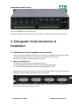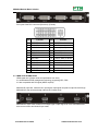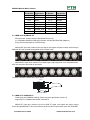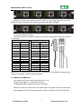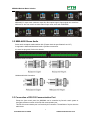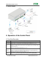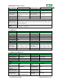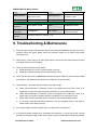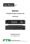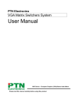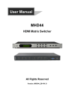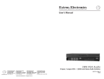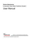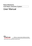
1
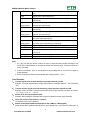
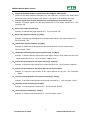
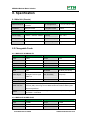
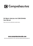
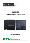
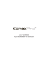
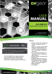
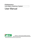
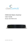
PTN Electronics
MMX88A Modular Matrix Switcher
User Manual
MMX Series ---Combo Matrix Switcher
Please read this manual carefully before using this product.
Notice:
This MMX88A Series Matrix Switchers User Manual is only an instruction for
operators, not for any maintenance usage. The functions described in this version
are updated till 29th March 2012. Any changes of functions and parameters since
then will be informed separately. Please refer to the dealers for the latest details.
This manual is copyright PTN Electronics Limited. All rights reserved. No part of
this publication may be copied or reproduced without the prior written consent of
PTN Electronics Limited.
MMX88A Modular Matrix Switcher
! Safety Operation Guide
In order to ensure the credibility use of the product and the user’s safety, please comply
with the following items during installation and maintenance:
The system must be earthed properly. Please do not use two blades plugs and ensure the
alternating power supply ranged from 100v to 240v and from 50Hz to 60Hz.
Do not put the switcher in a place of too hot or too cold.
To avoid any damage by over heat, please keep the working environment good in ventilation
to radiate the heat when running the switcher.
The switchers should be turned off when in rainy and humid days or nonuse for a long time,
The alternating power supply line should be disconnected with the power socket during the
following operation.
A. Take out or reinstall any component of the switcher
B. Disconnect or re-connect any connector of the switcher
Please do not attempt to maintain and uncover the switcher for there is a high-voltage
component inside and the risk of the electric shock.
Do not splash any chemical product or liquid on or near the equipment.
ii
MMX88A Modular Matrix Switcher
Contents
1. INTRODUCTION .......................................................... 1
1.1 About MMX88A Modular Matrix Switcher System ................................................ 1
1.2 MMX88A Modular Matrix Switcher Models ........................................................... 1
1.2.1 The MMX88A chassis (main unit) ...................................... 1
1.2.2 MMX88A signal card (changeable cards) ................................ 1
2. PACKING OF THE PRODUCT .............................................. 2
3. INSTALLATION ........................................................... 3
4. FRONT VIEW AND REAR VIEW OF THE PRODUCT ........................... 3
4.1 Front View of the MMX88A ..................................................................................... 3
4.1 Rear View of the MMX88A ...................................................................................... 3
5. CHANGEABLE CARDS INTRODUCTION & INSTALLATION ..................... 4
5.1 Introduction of the changeable cards and slots .................................................. 4
5.1.1 MMX-4I-DV & MMX-4O-DV ........................................... 4
5.1.2 MMX-4I-HD & MMX-4O-HD ........................................... 5
5.1.3 MMX-4I-VG ........................................................ 6
5.1.4 MMX-4I-SD & MMX-4O-SD ........................................... 7
5.1.5 MMX-4I-TP & MMX-4O-TP ........................................... 7
5.1.6 MMX-4I-FO & MMX-4O-FO ........................................... 8
5.2 MMX-AU88 Stereo Audio ........................................................................................ 9
5.3 Connection of RS-232 Communication Port......................................................... 9
5.3.1 Connection with Control Systems ..................................... 10
5.3.2 Connection with Computer ........................................... 10
5.4 Connection of TCP/IP Communication Port (Optional Function) ..................... 10
5.5 System Diagram .................................................................................................... 11
6. OPERATION OF THE CONTROL PANEL .................................... 11
6.1 Front Panel Description ....................................................................................... 11
6.2 Command Format of the Switching Operation ................................................... 12
6.3 Examples of Operation ......................................................................................... 12
7. COMMUNICATION PROTOCOL & COMMAND CODES ........................ 13
7.1 RS232 codes of regular switching....................................................................... 13
8. SPECIFICATION ......................................................... 16
8.1 Main Unit (Chassis)............................................................................................... 16
8.2 Changeable Cards ................................................................................................ 16
8.2.1 MMX-4I-DV & MMX-4O-DV .......................................... 16
8.2.2 MMX-4I-HD & MMX-4O-HD .......................................... 16
iii
MMX88A Modular Matrix Switcher
8.2.3 MMX-4I-VG .......................................................
8.2.4 MMX-4I-SD & MMX-4O-SD ..........................................
8.2.5 MMX-4I-TP & MMX-4O-TP ..........................................
8.2.6 MMX-4I-FO & MMX-4O-FO ..........................................
8.2.7 MMX-AU88 .......................................................
17
17
18
18
18
9. TROUBLESHOOTING & MAINTENANCE .................................... 19
iv
MMX88A Modular Matrix Switcher
1. Introduction
1.1 About MMX88A Modular Matrix Switcher System
MMX88A is a high performance video and audio modular matrix switcher. Various changeable cards
make MMX88A flexible and all-in-one solution for different projects. It can support different video
signals with cross switching. Every video or audio signal is transmitted and switched independently, this
will cause the least signal attenuation, so that make the output signal keep at high fidelity.
There are two series of changeable cards work with MMX88A, input card MMX-4I series and output
card MMX-4O series, all the cards support hot plug & play. Users can choose the right card for different
application. There are different signal card is used for processing different video signal, including: HMDI,
DVI, VGA, SDI, OPTICAL and HDMI TP etc.
MMX88A have power fail memory function and audio can break away from or follow the video to switch. It
has RS232 port for serial control and optional IP port for TCP/IP control, easily to be controlled by third-part
devices.
MMX88A can be used for different project, because of its changeable card design. It is the combo
solution for multimedia conference rooms, control rooms, broadcasting rooms, shopping center etc. It
will handle all the audiovisual management, including the switching, driving, scaling etc.
1-1 MMX88A
1.2 MMX88A Modular Matrix Switcher Models
1.2.1 The MMX88A chassis (main unit)
Specifications
Models
Height
Maximum Slot
2U
slots & 2 output
Power supplies
RS232 control
Single
√
Network
control
2 input card
MMX88A
Optional
card slots
1.2.2 MMX88A signal card (changeable cards)
To meet different situation and users, the MMX88A cards are classified into the following models:
1) MMX88A input cards
Specifications
Inputs
Signal Format
MMX-4I-HD
4
HDMI
MMX-4I-DV
4
DVI
MMX-4I-VG
4
VGA
Models
1
PTN Electronics Limited
www.PTN-electronics.com
MMX88A Modular Matrix Switcher
Specifications
Inputs
Signal Format
4
SDI
MMX-4I-FO
4
Fiber Optical
MMX-4I-TP
4
RJ45
Input
Signal Format
MMX-4O-HD
4
HDMI
MMX-4O-DV
4
DVI
MMX-4O-SD
4
SDI
MMX-4O-FO
4
Fiber Optical
MMX-4O-TP
4
RJ45
Models
MMX-4I-SD
2) MMX88A output cards
Specifications
Models
2. Packing of the Product
Pictures
Description
MMX88A modular matrix switcher (with empty slot
and empty cover)
RS-232 Communication Cord
Power Supply Cord
User manual
Rubber cushion
2
PTN Electronics Limited
www.PTN-electronics.com
MMX88A Modular Matrix Switcher
3. Installation
MMX88A modular matrix switchers adopt aluminium shell and can be stacked with other device.
Moreover, it is rack-mountable to install in the standard 19 inches case.
4. Front View and Rear View of the Product
4.1 Front View of the MMX88A
There are two parts in the front panel.
1: System monitor.
The system switching and status monitor.
2: Crystal buttons.
Crystal buttons, with green back-light indicating, which can insert customized label.
4.1 Rear View of the MMX88A
3
PTN Electronics Limited
www.PTN-electronics.com
MMX88A Modular Matrix Switcher
In the rear panel, there are maximum 4 card slots, including 2 input cards and 2 output cards. In MMX
series, only MMX88A has in-built audio card.
Remarks: The cards in the pictures are only for reference, user can choose and doing plug and play.
5. Changeable Cards Introduction &
Installation
5.1 Introduction of the changeable cards and slots
There are various changeable cards, which can insert to the MMX88A empty slot (hot-swop),
include different signals, such as DVI, HDMI, VGA, fiber optical, twisted pair etc.
Now, there is the one by one introduction for every card.
5.1.1 MMX-4I-DV & MMX-4O-DV
DVI signal card. (Please check the specification from 8.2.1)
It is fully compatible with HDMI1.3 and HDCP, not supporting analogy signal.
It is embedded the EDID management technology, supporting CEC, DDC.
MMX-4I-DV: input card, maximum four input signal. Input signal can pass to output device through
MMX-4O-DV, also can pass through other kinds of output cards.
MMX-4O-DV: output card, maximum four output signal. Output signal can come from MMX-4I-DV,
also can come from other kinds of input cards.
4
PTN Electronics Limited
www.PTN-electronics.com
MMX88A Modular Matrix Switcher
Pin Layout of the DVI-I connector (Dual-Link). (Female)
PIN
Function
PIN
Function
1
T.M.D.S.Data2-
13
T.M.D.S.Data3+
2
T.M.D.S.Data2+
14
+5V Power
3
T.M.D.S. Data 2/4 Shield
15
Ground (for +5V)
4
T.M.D.S. Data 4-
16
Hot Plug Detect
5
6
T.M.D.S. Data 4+
DDC Clock
17
18
T.M.D.S. Data 0-
T.M.D.S. Data 0+
7
DDC Data
19
T.M.D.S. Data 0/5 Shield
8
No Connect
20
T.M.D.S.Data5-
9
T.M.D.S.Data1-
21
T.M.D.S.Data5+
10
T.M.D.S.Data1+
22
T.M.D.S. Clock Shield
11
T.M.D.S.Data1/3 Shield
23
T.M.D. S. Clock +
12
T.M.D.S.Data3-
24
T.M.D.S .Clock-
5.1.2 MMX-4I-HD & MMX-4O-HD
HDMI signal card. (Please check the specification from 8.2.2)
It is embedded the EDID management technology, supporting CEC, DDC.
It is also compatible with DVI signal (HDCP required)
MMX-4I-HD: input card, maximum four input signal. Input signal can pass to output device through
MMX-4O-HD, also can pass through other kinds of output cards.
MMX-4O-HD: output card, maximum four output signal. Output signal can come from MMX-4I-HD,
also can come from other kinds of input cards.
5
PTN Electronics Limited
www.PTN-electronics.com
MMX88A Modular Matrix Switcher
Pin layout of the HDMI connectors (female).
Pin Number
Signal Name
Pin Number
Signal Name
1
TMDS Data 2+
20
SHELL
2
TMDS Data 2 Shield
19
Hot Plug Detect
3
TMDS Data 2-
18
+5V Power
4
TMDS Data 1+
17
Ground
5
6
TMDS Data 1 Shield
TMDS Data 1-
16
15
DDC Data
DDC Clock
7
TMDS Data 0+
14
No Connect
8
TMDS Data 0 Shield
13
CEC
9
TMDS Data 0-
12
TMDS Clock-
10
TMDS Clock+
11
TMDS Clock Shield
5.1.3 MMX-4I-VG
VGA signal card. (Please check the specification from 8.2.3)
Compatible with C-Video, YUV, YC (Factory preseted function).
The bandwidth is up to 350MHz (-3dB);
Supporting RGBHV, RGsB, RGBS, RsGsBs, YUV, YC and Composite video.
MMX-4I-VG: input card, maximum four input signal. Input signal can pass to output device through
other kinds of output cards.
Pin layout of the VGA connectors (female):
6
PTN Electronics Limited
www.PTN-electronics.com
MMX88A Modular Matrix Switcher
Pin Number
Signal Name
Pin Number
Signal Name
Pin 1
RED
Pin 9
KEY/PWR
Pin 2
GREEN
Pin 10
GND
Pin 3
BLUE
Pin 11
ID0/RES
Pin 4
ID2/RES
Pin 12
ID1/SDA
Pin 5
GND
Pin 13
HSync
Pin 6
RED_RTN
Pin 14
VSync
Pin 7
GREEN_RTN
Pin 15
ID3/SCL
Pin 8
BLUE_RTN
5.1.4 MMX-4I-SD & MMX-4O-SD
SDI signal card. (Please check the specification from 8.2.4)
It is compatible with different SDI signal formats, including SD/HD/3G-SDI (adaptive)
Every port has loop output for local monitoring.
MMX-4I-SD: input card, maximum four input signal. Input signal can pass to output device through
MMX-4O-SD, also can pass through other kinds of output cards.
MMX-4O-SD: output card, maximum four output signal. Output signal can come from MMX-4I-SD,
also can come from other kinds of input cards.
The BNC connector is shown as the figure below.
Tip (+)
Sleeve ( )
BNC Connector
5.1.5 MMX-4I-TP & MMX-4O-TP
Twisted pair card (HDMI/DVI extend). (Please check the specification from 8.2.5)
Support HDTV, compatible with HDMI1.4 and HDCP
MMX-4I-TP: input card, maximum input four HDMI TP signal. Input signal can pass to output
device through MMX-4O-TP, also can pass through other kinds of output cards, works with TPHD402T.
7
PTN Electronics Limited
www.PTN-electronics.com
MMX88A Modular Matrix Switcher
MMX-4O-TP: output card, maximum output four HDMI TP signal. Output signal can come from
MMX-4I-TP, also can come from other kinds of input cards, works with TPHD402R.
Pin layout of the RJ45 connectors:
Two different connection standards can be chose, the same cable should use the same standard
on both sides.
TIA/EIA T568A
Pin
Cable color
TIA/EIA T568B
Pin
Cable color
1
green white
1
orange white
2
green
2
orange
3
orange white
3
green white
4
blue
4
blue
5
blue white
5
blue white
6
orange
6
green
7
brown white
7
brown white
8
brown
8
brown
1st Ground
2nd Ground
4--5
3--6
1st Ground
2nd Ground
4--5
1--2
3rd Group
1--2
3rd Group
3--6
4th Group
7--8
4th Group
7--8
Notice: Cable connectors MUST be metal one, the shielded layer of cable MUST be connected to the
connector’s metal shell, to make a better transmission.
5.1.6 MMX-4I-FO & MMX-4O-FO
Fiber optical card (Please check the specification from 8.2.6).
Using full digital signal non-compression technology.
Compatible with HDTV, transmitted resolution up to 1080p.
MMX-4I-FO: input card, maximum four fiber optical signal. Input signal can pass to output device
through MMX-4O-FO, also can pass through other kinds of output cards, works with FODV300T.
8
PTN Electronics Limited
www.PTN-electronics.com
MMX88A Modular Matrix Switcher
MMX-4O-FO: output card, maximum output four fiber optical signal. Output signal can come from
MMX-4I-FO, also can come from other kinds of input cards, works with FODV300R.
5.2 MMX-AU88 Stereo Audio
Stereo audio crosspoint matrix switcher 8x8. (Please check the specification from 8.2.7)
It supports the balanced/unbalanced audio, by different connection.
It is not a hot plug card, fixed on the chassis.
Balanced Audio Connection:
Unbalanced Audio Connection:
5.3 Connection of RS-232 Communication Port
Except the front control panel, the MMX88A can be controlled by far-end control system or
through the Ethernet control via the RS-232 communication port.
This RS-232 communication port is a female 9-pin D connector. The definition of its pins is as the
table below.
9
PTN Electronics Limited
www.PTN-electronics.com
MMX88A Modular Matrix Switcher
Pin No.
1
2
3
4
5
6
7
8
9
Name
N/u
Tx
Rx
N/u
Gnd
N/u
N/u
N/u
N/u
Function
Unused
Transmit
Receive
Unused
Ground
Unused
Unused
Unused
Unused
5.3.1 Connection with Control Systems
With the RS-232 port, the MMX88A can be controlled by several kinds of control systems.
5.3.2 Connection with Computer
When the MMX88A connects to the RS232 port of a computer with control software, users can
control it by that computer.
To control the switcher, users may use the RS232 software
5-1 Connection between MMX88 and the computer
5.4 Connection of TCP/IP Communication Port (Optional Function)
The MMX88A can work with the PTN model “PTNET”, to enable the TCP/IP function.
The PTNET is a programmable RCP/IP to RS232 processor, which is built in the FTP and fixed IP
address inside and working compatible with internet.
10
PTN Electronics Limited
www.PTN-electronics.com
MMX88A Modular Matrix Switcher
5.5 System Diagram
6. Operation of the Control Panel
6.1 Front Panel Description
Buttons
Function Description
INPUTS
Input buttons.
OUTPUTS
Output buttons. It is the number of every output channel, ranging from "1" to "8".
It is the number of every input channel, ranging from "1" to "8".
AV
AV synchronal button: To transfer video and audio signal synchronously by the switcher.
Example: To transfer both the video and the audio signals from input channel No.3 to
output channel No.4.
Operation: Press buttons in this order “AV”, “3”, “4”.
VIDEO
Video button: To transfer only video signals from input channel to output channel
Example: To transfer video signals from input channel No.3 to output channel No.4.
Operation: Press buttons in this order “VIDEO”, “3”, “4”.
AUDIO
Audio button: To transfer only audio signals from input channel to output channel
Example: To transfer audio signals from input channel No.2 to output channel No.3.
11
PTN Electronics Limited
www.PTN-electronics.com
MMX88A Modular Matrix Switcher
Operation: Press buttons in this order “AUDIO”, “2”, “3”
ALL
All button: To transfer an input channel to all output channels or switch off all the output
channels
Example1: To transfer video and audio signals from input channel No.7 to all output
channels
Operation: Press buttons in this order “7”, “ALL”
Example2: To transfer all input signals to the corresponding output channels
respectively. In another word, to switch to this status: 1->1, 2->2, 3->3, 4->4……8->8.
Operation: Press buttons in this order “ALL”, “THROUGH”
THROUGH
Through button: To transfer the signals directly to the corresponding output channels
Example: To transfer the signals from input channel No. 3 to their corresponding output
channels
Operation: Press buttons in this order “3”, “THROUGH”
UNDO
Undo button: To resume to the status before the command just performed
Backspace button: To backspace the latest input button
6.2 Command Format of the Switching Operation
With the front control panel, the MMX88A could be control directly and rapidly by pressing the buttons
under below format.
“Input Channel” + “Switch Mode” +“Output Channel 1”
“Switch Mode”: Audio & Video synchronal or break away switching mode, includes buttons “AV”,
“Audio”, “Video”.
“Input Channel”: Fill with the number of input channel to be controlled
“Output Channel”: Fill with the number of output channels to be control
6.3 Examples of Operation
Example 1:To transfer video and audio signals from input channel No.1 to output channel
No.3,4
1
2
3
4
1, Press the button for input channel number“1”
AV
2
Video
3
Audio
2, Press the button for switching mode “AV” for the switching mode of video
and audio (“Audio” for the switching mode of audio only; “Video” for the
switching mode of video only)
4
12
PTN Electronics Limited
www.PTN-electronics.com
MMX88A Modular Matrix Switcher
3, Press the button for the first output channel number “3”
2
3
4
4, Press the button for the second output channel number “4”
Then, switching OK! Audio/video switching from “1” to “3” and “4”
7. Communication Protocol & Command
Codes
7.1 RS232 codes of regular switching
With this command system, using the RS232 software is able to control and operate the MMX88
remotely.
Communication protocol:
Baud rate: 9600
Data bit: 8
Stop bit: 1
Parity bit: none
Command
Types
Command
Codes
Functions
System Command
/*Type;
Inquire the models information.
/%Lock;
Lock the keyboard of the control panel on the Matrix.
/%Unlock;
Unlock the keyboard of the control panel on the Matrix.
/^Version;
Inquire the version of firmware
/:MessageOff;
Turn off the feedback command from the com port. It will only show
the “switcher OK”.
/:MessageOn;
Turn on the feedback command from the com port.
EDIDM[X]B[Y].
Manually adjust the EDID data, Copy the EDID data of output[X] to
the input[Y].
EDIDMInit.
Recover the factory default EDID data
Undo.
To cancel the previous operation.
Demo.
Switch to the “demo” mode, 1->1, 2->2, 3->3 … and so on.
Operation
Command
[x1]All.
Transfer signals from the input channel [x1] to all output channels
All#.
Transfer all input signals to the corresponding output channels
respectively.
All$.
Switch off all the output channels.
13
PTN Electronics Limited
www.PTN-electronics.com
MMX88A Modular Matrix Switcher
[x1]#.
Transfer signals from the input channel [x1] to the output channel
[x1].
[x1]$.
Switch off the output channel [x1].
[x1] V[x2].
Transfer the video signals from the input channel [x1] to the output
channel [x2].
[x1]
V[x2],[x3],[x4].
Transfer the video signals from the input channel [x1] to the output
channels [x2], [x3] and [x4].
[x1] A[x2].
Transfer the audio signals from the input channel [x1] to the output
channel [x2].
[x1]
A[x2],[x3],[x4].
Transfer the audio signals from the input channel [x1] to the output
channels [x2], [x3] and [x4].
[x1] B[x2].
Transfer both the video and the audio signals from the input channel
[x1] to the output channel [x2].
[x1]
B[x2],[x3],[x4].
Transfer both the video and the audio signals from the input channel
[x1] to the output channels [x2], [x3] and [x4].
Status[x1].
Inquire the input channel to the output channel [x1].
Status.
Inquire the input channel to the output channels one by one.
Save[Y].
Save the present operation to the preset command [Y]. [Y] ranges
from 0 to 9.
Recall[Y].
Recall the preset command [Y].
Clear[Y].
Clear the preset command [Y].
Note:
1. [x1], [x2], [x3] and [x4] are the symbols of input or output channels ranged according to the
model of the matrix switcher. If the symbols exceed the effective range, it would be taken as a
wrong command.
2. In above commands, “[”and “]” are symbols for easy reading and do not need to be typed in
actual operation.
3. Please remember to end the commands with the ending symbols “.” and “;”.
Detail Examples:
1、 Transfer signals from an input channel to all output channels: [x1]All.
Example: To transfer signals from the input channel No.3 to all output channels. Run Command:
“3All.”
2、 Transfer all input signals to the corresponding output channels respectively: All#.
Example: If this command is carried out on an MVG1616-A matrix switcher, the status of it will be:
1->1, 2->2, 3->3, 4->4……16->16.
3、 Switch off all the output channels: All$.
Example: After running this command, there will be no signals on all the output channels.
4、 Check the version of the firmware: /^Version;
To check the version of the firmware.
5、 Switch off the detail feedback command from the COM port: /:MessageOff;
Switch off the detail feedback information from the COM port. But, it will leave the “switch OK” as
14
PTN Electronics Limited
www.PTN-electronics.com
MMX88A Modular Matrix Switcher
the feedback, when you switch the matrix.
6、 Switch on the detail feedback command from the COM port: /:MessageOn;
Switch on the detail feedback information from the COM port. it will show the detail switch
information when it switch. Example: when switch 1->2 for Audio, it will feedback “A01 to 02”.
7、 Transfer signals from an input channel to the corresponding output channel: [x]#.
Example: To transfer signals from the input channel No.5 to the output channel No.5.
Command: “5#.”
Run
8、Switch off an output channel: [x]$.
Example: To switch off the output channel No.5.
Run Command: “5$.”
9、Switch video signals command: [x1] V[x2].
Example: To transfer the video signals from the input channel No.3 to the output channel No.5.
Run Command: “3V5.”
10、Switch audio signals command: [x1] A[x2].
Example: To Transfer the audio signals from the input channel No.10 to the output channel
Run Command: “10A2.”
11、Switch both video and audio signals synchronously: [x1] B[x2].
Example: To transfer both the video and the audio signals from the input channel No.120 to the
output channel No.12,13,15. Run Command: “120B12,13,15.”
12、Inquire the input channel to the output channel [x]: Status[x].
Example: To inquire the input channel to the output channel No.23.
Run Command: “Status23.”
13、Inquire the input channel to the output channels one by one: Status.
Example: To inquire the input channel to the output channels one by one.
“Status.”
Run Command:
14、Save the present operation to the preset command [Y]: Save[Y].
Example: To save the present operation to the preset command No.7.
Run Command: “Save7.”
15、Recall the preset command [Y]: Recall[Y].
Example: To recall the preset command No.5. Run Command: “Recall5.”
16、Clear the preset command [Y]: Clear[Y].
Example: To clear the preset command No.5.
Run Command: “Clear5.”
15
PTN Electronics Limited
www.PTN-electronics.com
MMX88A Modular Matrix Switcher
8. Specification
8.1 Main Unit (Chassis)
Control parts
Serial control port
RS-232, 9-pin female D
connector
Pin Configurations
2 = TX, 3 = RX, 5 = GND
Front panel control
Buttons
Installation
Rack Mountable
Options
TCP/IP control by PTNET(PTN's programmable interface)
General
Power Supply
110VAC ~ 240VAC, 50/60Hz
Humidity
10% ~ 90%
Temperature
-20 ~ +70
Power Consumption
50W
Case Dimension
W482.6 x H88 x D320mm
Product Weight
5Kg
8.2 Changeable Cards
8.2.1 MMX-4I-DV & MMX-4O-DV
Input
Output
Input
4 DVI;
Output
4 DVI;
Input Connector
Female DB24+5
Output Connector
Female DB24+5
Input Level
T.M.D.S. 2.9V/3.3V
output Level
T.M.D.S. 2.9V/3.3V
Input Impedance
75Ω
Output Impedance
75Ω
0 dB
Bandwidth
340 MHz (10.2 Gbit/s)
Max Time-delay
5nS (±1nS)
Crosstalk
<-50dB@5MHz
General
Gain
DVI 1.0 standard DVI-D
Video Signal
full digital T.M.D.S signal
HDMI 1.3
Switching Speed
200ns (Max.)
HDMI standard
HDMI 1.3 standard
Supports Extended Display Identification Data (EDID) and Display Data
EDID and DDC
Channel (DDC) data using DVI and HDMI standards. EDID and DDC signals
are actively buffered
HDCP
Compliant with High-bandwidth Digital Content Protection (HDCP) using DVI
and HDMI 1.3 standards
8.2.2 MMX-4I-HD & MMX-4O-HD
Input
Output
Input
4 HDMI
Output
4 HDMI
Input Connector
Female HDMI
Output Connector
Female HDMI
Input Level
T.M.D.S. 2.9V/3.3V
output Level
T.M.D.S. 2.9V/3.3V
16
PTN Electronics Limited
www.PTN-electronics.com
MMX88A Modular Matrix Switcher
Input Impedance
75Ω
Output Impedance
75Ω
0 dB
Bandwidth
340 MHz (10.2 Gbit/s)
Max Time-delay
5nS (±1nS)
Crosstalk
<-50dB@5MHz
General
Gain
DVI 1.0 standard DVI-D
Video Signal
full digital T.M.D.S signal
Switching Speed
200ns (Max.)
HDMI standard
HDMI 1.3 standard
HDMI 1.3
Supports Extended Display Identification Data (EDID) and Display Data
EDID and DDC
Channel (DDC) data using DVI and HDMI standards. EDID and DDC signals
are actively buffered
HDCP
Compliant with High-bandwidth Digital Content Protection (HDCP) using DVI
and HDMI 1.3 standards
8.2.3 MMX-4I-VG
Input
Input
4 VGA
Input Connector
Female 15 pin HD
Input Coupling
AC coupling only
Input Level
0.5 ~ 2.0Vp-p
Input Impedance
75Ω
General
Gain
0 dB
Bandwidth
VGA-UXGA,RGBHV,RGBS,
Video Signal
RGsB, RsGsBs, component
VGA-UXGA,RGBHV,RGBS,
Video Type
video, S-video & C-video .
Switching Speed
200ns (Max.)
350MHz (-3dB), fully load
RGsB, RsGsBs, component
video, S-video & C-video .
Crosstalk
<-50dB@5MHz
8.2.4 MMX-4I-SD & MMX-4O-SD
Input
Output
Input
4 SDI
Output
4 SDI
Input Connector
Female BNC
Output Connector
Female BNC
Input Level
0.8Vp-p ± 10%
output Level
0.8Vp-p ± 10%
Input Impedance
75Ω
Output Impedance
75Ω
General
Gain
Transmission
Distance
Input Return Loss
Video Standard
Unity
300M (Max.)
<-14 dB @ 1 MHz ~ 1.5
GHz
SMPTE 292M, SMPTE
259M, SMPTE 424M,
Maximum Data
Rate
Data rate Lock
Input Return Loss
Data Type
2.97 Gbps
Auto
<-14 dB @ 1 MHz ~ 1.5
GHz
8bit, 10bit
17
PTN Electronics Limited
www.PTN-electronics.com
MMX88A Modular Matrix Switcher
ITU-RBT.601,
ITU-RBT.1120
8.2.5 MMX-4I-TP & MMX-4O-TP
Video Input
Video Output
Input
4 RJ45
Output
4 RJ45
Input Connector
Female RJ45
Output Connector
Female RJ45
Input Impedance
75Ω
Output
Impedance
75Ω
Video General
Gain
Resolution range
SNR
0dB ~ 10dB@100MHz
Bandwidth
800x600 ~ 1920x1200
Transmission
Distance
10.2Gbps
70M(Max)
>70dB@ 100MHz-100M
Return Loss
<-30dB@ 5KHz
THD
<0.005%@1KHz
Min.~Max. Level
<0.3V ~ 1.45Vp-p
HDMI Standard
Support
Differential
±10° @ 135MHz_100M
HDMI1.4
and
HDCP
Phasic Erro
8.2.6 MMX-4I-FO & MMX-4O-FO
Input
Input
Input Connector
Output
4 Fiber Optical
4 SPF Fiber Optical
Connector
Output
Output Connector
4 Fiber Optical
4 SPF Fiber Optical
Connector
Input Level
0.8Vp-p ± 10%
output Level
0.8Vp-p ± 10%
Input Impedance
75Ω
Output Impedance
75Ω
Fiber Type
Single Mode
Fiber Type
Single Mode
-5 dBm
Max. sensitivity
-18 dBm
13 dB
Max Channel Rate
4.25 Gbps
Unity
Max. Data Rate
2.97 Gbps
20Km (Max.)
Data rate Lock
Auto
Transmission
Consumption
Maximum loss
General
Gain
Transmission
Distance
Input Return Loss
<-14 dB @ 1 MHz ~ 1.5
GHz
Input Return Loss
<-14 dB @ 1 MHz ~ 1.5
GHz
SMPTE 292M, SMPTE
Video Standard
259M, SMPTE 424M,
ITU-RBT.601,
Data Type
8bit, 10bit
ITU-RBT.1120
8.2.7 MMX-AU88
Input
Output
18
PTN Electronics Limited
www.PTN-electronics.com
MMX88A Modular Matrix Switcher
Input
Input Connector
Input Impedance
8 stereo
3.5 mm captive screw
connectors, 5 pole
Output
8 stereo
3.5 mm captive screw
Output Connector
connectors, 5 pole
>10KΩ
Output Impedance
50Ω
20Hz~20KHz, ±0.5dB
CMRR
>90dB@20Hz~20KHz
>80dB@1KHz
THD + Noise
General
Frequency
Response
Stereo Channel
Separation
Audio Bits per
Sample
1% @ 1 KHz, 0.3% @ 20
KHz at nominal level
18 bits per channel, 2 channels (L, R)
9. Troubleshooting & Maintenance
1)
When the output image in the destination device connected to the MMX88A has ghost, such as the
projector output with ghost, please check the projector’s setting or try another high quality
connection cord.
2)
When there is a color losing or no video signal output, it may be the connectors between the input
and output end do not connect tightly.
3)
When the remote controller doesn’t works:
A. Maybe the battery is run out of, please change a new one.
B. Maybe the controller is broken, please ask the dealer to fix it.
4)
When user can not control the MMX88A by computer through its COM port, please check the COM
port number in the software and make sure the COM port is in good condition.
5)
When switching , the beeper beeps but without any output image:
A.
Check with oscilloscope or multimeter if there is any signal at the input end. If there is no
signal input, it may be the input connection cord broken or the connectors loosen.
B. Check with oscilloscope or multimeter if there is any signal at the output end. If there is no
signal output, it may be the output connection cord broken or the connectors loosen.
C. Please make sure the destination device is exactly on the controlled output channel
D. If it is still the same after the above checking, it may be something wrong in the switcher.
Please send it to the dealer for fixing.
6)
If the output image is interfered, please make sure the system is earthed well.
7)
If the static becomes stronger when connecting the connectors, it may be due to the incorrect
grounding of the power supply, Please earth it again correctly, and otherwise it would bring damage
19
PTN Electronics Limited
www.PTN-electronics.com
MMX88A Modular Matrix Switcher
to the switcher or shorten its natural life.
8)
If the MMX88A cannot be controlled by the keys on the front panel, RS232 port or remote controller,
the host may has already been broken. Please send it to the dealer for fixing.
Remarks: For any more questions or problems, please try to get help from your local distributor, or
email PTN at [email protected].
20
PTN Electronics Limited
www.PTN-electronics.com