1
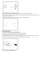
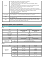
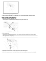
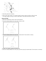
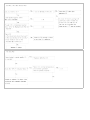
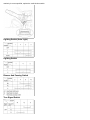
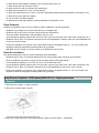
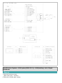
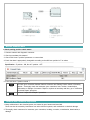
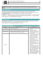
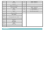
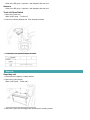
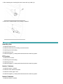
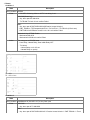
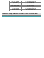
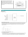
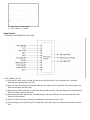
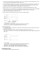
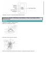
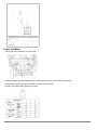
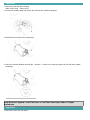
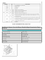
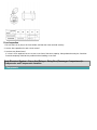
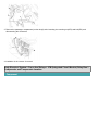
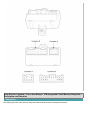
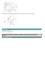
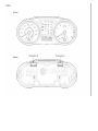
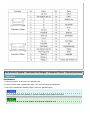
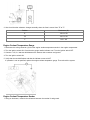
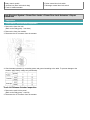
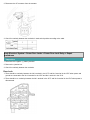
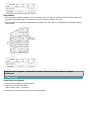
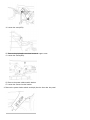
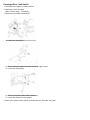
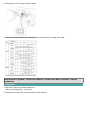
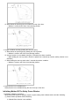
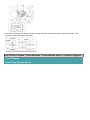
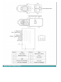
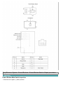
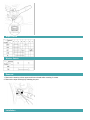
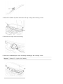
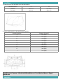
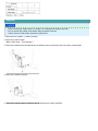
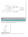
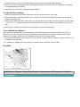
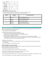
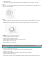
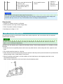
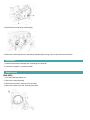
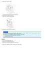
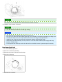
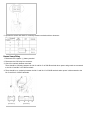
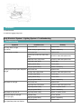
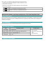
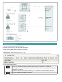
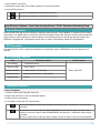
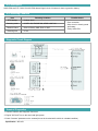
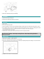
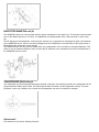
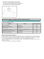
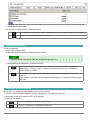
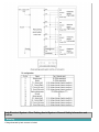
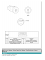
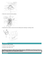
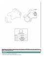
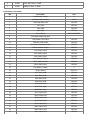
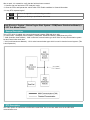
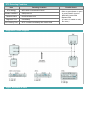
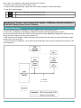
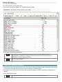
2. Also check that the resistance changes smoothly when the float is moved from "E" to "F".
Position
Resistance (Ω)
E
193.4 ± 2Ω
1/2
104.3 ± 2Ω
F
13.5 ± 2Ω
Engine Coolant Temperature Gauge
1. Disconnect the wiring connector (A) from the engine coolant temperature sender in the engine compartment.
2. Turn the ignition switch ON. Check that the gauge needle indicates cool. Turn the ignition switch OFF.
3. Connect a 12V, 3.4 watt test bulb between the harness side connector and ground.
4. Turn the ignition switch ON.
5. Verify that the test bulb flashes and that the indicator moves to HOT.
If operation is not as specified, replace the engine coolant temperature gauge. Then recheck the system.
Engine Coolant Temperature Sender
1. Using an ohmmeter, measure the resistance between the terminal 2 and ground.