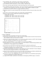
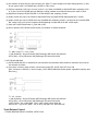
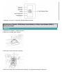
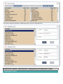
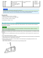
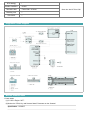
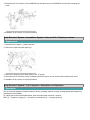
1
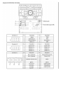
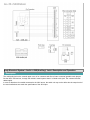
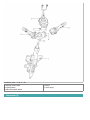
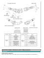
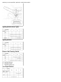
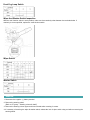
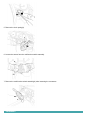
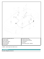
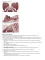
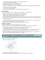
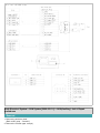
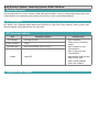
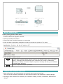
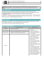
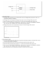
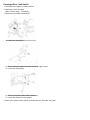
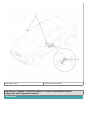
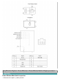
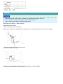
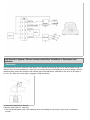
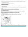
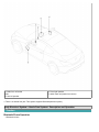
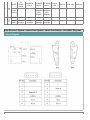
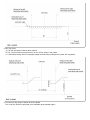
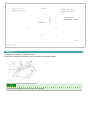
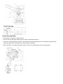
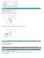
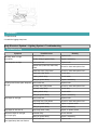
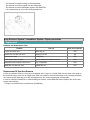
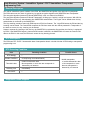
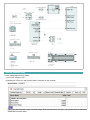
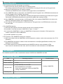
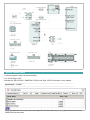
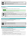
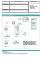
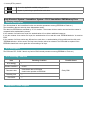
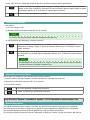
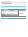
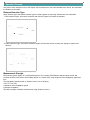
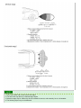
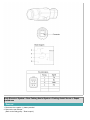
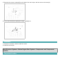
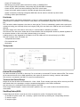
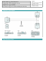
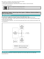
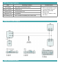
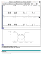
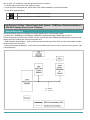
Terminal and Connector Inspection
1. Many malfunctions in the electrical system are caused by poor harness and terminals. Faults can also be caused by
interference from other electrical systems, and mechanical or chemical damage.
2. Thoroughly check connectors for looseness, poor connection, bending, corrosion, contamination, deterioration,or
damage.
3. Has a problem been found?
▶ Repair as necessary and go to "Verification of Vehicle Repair" procedure.
▶ Go to "Signal circuit Inspection" procedure.
Signal circuit Inspection
■ Check power in harness
1. Ignition "OFF"
2. Disconnect Auto Head Lamp Leveling Sensor harness connector.
3. Ignition "ON", HEAD LAMP "ON"(ENGINE "OFF").
4. Measure voltage between H/LP (LO) Relay terminal of AHLS ECM harness connector and chassis ground.
Specification : B+
5. Is "voltage" display near the specified value?
▶ Check the condition of connected part and go to "Verification Vehicle Repair" procedure.
▶ Check for circuit in harness between ECM and headlamp switch signal line.
▶ Repair as necessary and then go to "Verification of Vehicle Repair" procedure.
▶ After its repair done, Perform the lamp actuation by GDS in order to verify its normal operation.
Verification of Vehicle Repair
After a repair, it is essential to verifying that the fault has been corrected.
1. Connect scan tool and select "Diagnostic Trouble Codes(DTCs)" mode.
2. Using scantool, Clear DTC.
3. Operate the vehicle within DTC Enable conditions in General information.
4. Are any DTCs present ?
▶ Go to the applicable troubleshooting procedure.
▶ System is performing to specification at this time.
Body Electrical System > Head lamp leveling Device > C1604 ECU Fault
General Description
AHLS provides driver with the best visibility by adjusting vertical direction of the headlamp. It consists of AHLS ECU,
Linkage and Headlamp actuator. AHLS ECU is composed of many IC components, such as A/D(AD converter),
EEPROM, ROM, RAM and others.It also contains several different parameter-sets which defines the behavior in
different car types and respect different mounting places. For efficient operation of system, The internal components of
ECM ( A/D , EEPROM, ROM, RAM ) are checked internally during every start-up sequence.