1
®
PowerPro™
User Manual
80A5000_MA001_10
November 2009
6024 Silver Creek Valley Road, San Jose, California 95138
Telephone: (800) 345-7015 • (408) 284-8200 • FAX: (408) 284-2775
Printed in U.S.A.
©2009 Integrated Device Technology, Inc.
GENERAL DISCLAIMER
Integrated Device Technology, Inc. reserves the right to make changes to its products or specifications at any time, without notice, in order to improve design or performance
and to supply the best possible product. IDT does not assume any responsibility for use of any circuitry described other than the circuitry embodied in an IDT product. The
Company makes no representations that circuitry described herein is free from patent infringement or other rights of third parties which may result from its use. No license is
granted by implication or otherwise under any patent, patent rights or other rights, of Integrated Device Technology, Inc.
CODE DISCLAIMER
Code examples provided by IDT are for illustrative purposes only and should not be relied upon for developing applications. Any use of the code examples below is completely
at your own risk. IDT MAKES NO REPRESENTATIONS OR WARRANTIES OF ANY KIND CONCERNING THE NONINFRINGEMENT, QUALITY, SAFETY OR SUITABILITY
OF THE CODE, EITHER EXPRESS OR IMPLIED, INCLUDING WITHOUT LIMITATION ANY IMPLIED WARRANTIES OF MERCHANTABILITY, FITNESS FOR A PARTICULAR PURPOSE, OR NON-INFRINGEMENT. FURTHER, IDT MAKES NO REPRESENTATIONS OR WARRANTIES AS TO THE TRUTH, ACCURACY OR COMPLETENESS
OF ANY STATEMENTS, INFORMATION OR MATERIALS CONCERNING CODE EXAMPLES CONTAINED IN ANY IDT PUBLICATION OR PUBLIC DISCLOSURE OR
THAT IS CONTAINED ON ANY IDT INTERNET SITE. IN NO EVENT WILL IDT BE LIABLE FOR ANY DIRECT, CONSEQUENTIAL, INCIDENTAL, INDIRECT, PUNITIVE OR
SPECIAL DAMAGES, HOWEVER THEY MAY ARISE, AND EVEN IF IDT HAS BEEN PREVIOUSLY ADVISED ABOUT THE POSSIBILITY OF SUCH DAMAGES. The code
examples also may be subject to United States export control laws and may be subject to the export or import laws of other countries and it is your responsibility to comply with
any applicable laws or regulations.
LIFE SUPPORT POLICY
Integrated Device Technology's products are not authorized for use as critical components in life support devices or systems unless a specific written agreement pertaining to
such intended use is executed between the manufacturer and an officer of IDT.
1. Life support devices or systems are devices or systems which (a) are intended for surgical implant into the body or (b) support or sustain life and whose failure to perform,
when properly used in accordance with instructions for use provided in the labeling, can be reasonably expected to result in a significant injury to the user.
2. A critical component is any components of a life support device or system whose failure to perform can be reasonably expected to cause the failure of the life support device
or system, or to affect its safety or effectiveness.
IDT, the IDT logo, and Integrated Device Technology are trademarks or registered trademarks of Integrated Device Technology, Inc.
Contents
About this Document . . . . . . . . . . . . . . . . . . . . . . . . . . . . . . . . . . . . . . 17
1. Functional Overview. . . . . . . . . . . . . . . . . . . . . . . . . . . . . . . . . . . . 23
1.2
1.1.1
PowerPro Features. . . . . . . . . . . . . . . . . . . . . . . . . . . . . . . . . . . . . 24
1.1.2
PowerPro Benefits . . . . . . . . . . . . . . . . . . . . . . . . . . . . . . . . . . . . . 26
1.1.3
PowerPro Typical Applications. . . . . . . . . . . . . . . . . . . . . . . . . . . 27
Architecture . . . . . . . . . . . . . . . . . . . . . . . . . . . . . . . . . . . . . . . . . . . . . . . . 30
1.2.1
Processor Bus (PB) Interface. . . . . . . . . . . . . . . . . . . . . . . . . . . . . 32
1.2.2
SDRAM Interface . . . . . . . . . . . . . . . . . . . . . . . . . . . . . . . . . . . . . 32
1.2.3
FLASH/ROM Interface . . . . . . . . . . . . . . . . . . . . . . . . . . . . . . . . . 33
1.2.4
Registers . . . . . . . . . . . . . . . . . . . . . . . . . . . . . . . . . . . . . . . . . . . . 33
1.2.5
I2C Interface . . . . . . . . . . . . . . . . . . . . . . . . . . . . . . . . . . . . . . . . . 33
1.2.6
General Purpose I/O Port. . . . . . . . . . . . . . . . . . . . . . . . . . . . . . . . 33
1.2.7
UART Interface . . . . . . . . . . . . . . . . . . . . . . . . . . . . . . . . . . . . . . . 34
1.2.8
JTAG Interface . . . . . . . . . . . . . . . . . . . . . . . . . . . . . . . . . . . . . . . 34
2. Processor Bus Interface . . . . . . . . . . . . . . . . . . . . . . . . . . . . . . . . . 35
2.2
2.3
2.1.1
Interface Support . . . . . . . . . . . . . . . . . . . . . . . . . . . . . . . . . . . . . . 35
2.1.2
Terms. . . . . . . . . . . . . . . . . . . . . . . . . . . . . . . . . . . . . . . . . . . . . . . 36
Processor Bus Interface . . . . . . . . . . . . . . . . . . . . . . . . . . . . . . . . . . . . . . . 36
2.2.1
Overview . . . . . . . . . . . . . . . . . . . . . . . . . . . . . . . . . . . . . . . . . . . . 36
2.2.2
PowerPro as PB Slave . . . . . . . . . . . . . . . . . . . . . . . . . . . . . . . . . . 36
2.2.3
Address Phase . . . . . . . . . . . . . . . . . . . . . . . . . . . . . . . . . . . . . . . . 37
2.2.4
Data Phase . . . . . . . . . . . . . . . . . . . . . . . . . . . . . . . . . . . . . . . . . . . 41
2.2.5
Termination . . . . . . . . . . . . . . . . . . . . . . . . . . . . . . . . . . . . . . . . . . 46
Processor Bus Interface Arbitration . . . . . . . . . . . . . . . . . . . . . . . . . . . . . . 49
2.3.1
PowerPro User Manual
80A5000_MA001_10
Data Bus Arbitration . . . . . . . . . . . . . . . . . . . . . . . . . . . . . . . . . . . 51
3
Contents
2.4
2.3.2
Address Arbitration . . . . . . . . . . . . . . . . . . . . . . . . . . . . . . . . . . . . 51
2.3.3
Delay Sampling of Transaction Start Signal . . . . . . . . . . . . . . . . . 52
2.3.4
Bus Parking . . . . . . . . . . . . . . . . . . . . . . . . . . . . . . . . . . . . . . . . . . 52
Endian Conversion . . . . . . . . . . . . . . . . . . . . . . . . . . . . . . . . . . . . . . . . . . . 52
3. FLASH/ROM Interface . . . . . . . . . . . . . . . . . . . . . . . . . . . . . . . . . 53
3.2
Changing the Configuration of a FLASH/ROM Bank . . . . . . . . . . . . . . . . 54
3.3
FLASH/ROM Signals. . . . . . . . . . . . . . . . . . . . . . . . . . . . . . . . . . . . . . . . . 54
3.3.1
Time-Multiplexed SDRAM Signals . . . . . . . . . . . . . . . . . . . . . . . 58
3.3.2
Time-Multiplexed Processor Bus Signals . . . . . . . . . . . . . . . . . . . 59
3.4
FLASH/ROM Data Port . . . . . . . . . . . . . . . . . . . . . . . . . . . . . . . . . . . . . . . 60
3.5
Address Mapping . . . . . . . . . . . . . . . . . . . . . . . . . . . . . . . . . . . . . . . . . . . . 60
3.6
3.7
3.5.1
Multiplexed Address Signals . . . . . . . . . . . . . . . . . . . . . . . . . . . . . 60
3.5.2
Address Mapping . . . . . . . . . . . . . . . . . . . . . . . . . . . . . . . . . . . . . . 61
Transactions . . . . . . . . . . . . . . . . . . . . . . . . . . . . . . . . . . . . . . . . . . . . . . . . 67
3.6.1
Processor Bus Transactions . . . . . . . . . . . . . . . . . . . . . . . . . . . . . . 67
3.6.2
Reads . . . . . . . . . . . . . . . . . . . . . . . . . . . . . . . . . . . . . . . . . . . . . . . 67
3.6.3
Writes . . . . . . . . . . . . . . . . . . . . . . . . . . . . . . . . . . . . . . . . . . . . . . . 68
Connecting FLASH/ROM to PowerPro . . . . . . . . . . . . . . . . . . . . . . . . . . . 69
3.7.1
Typical Configurations . . . . . . . . . . . . . . . . . . . . . . . . . . . . . . . . . 70
4. SDRAM Interface . . . . . . . . . . . . . . . . . . . . . . . . . . . . . . . . . . . . . . 75
4.2
Supported SDRAM Configurations . . . . . . . . . . . . . . . . . . . . . . . . . . . . . . 76
4.2.1
4.3
SDRAM Operation . . . . . . . . . . . . . . . . . . . . . . . . . . . . . . . . . . . . . . . . . . . 78
4.4
Registers . . . . . . . . . . . . . . . . . . . . . . . . . . . . . . . . . . . . . . . . . . . . . . . . . . . 79
4.5
Initialization . . . . . . . . . . . . . . . . . . . . . . . . . . . . . . . . . . . . . . . . . . . . . . . . 79
4.5.1
4.6
4.7
4
Memory Bank Definition . . . . . . . . . . . . . . . . . . . . . . . . . . . . . . . . 76
SDRAM Datapath Tuning . . . . . . . . . . . . . . . . . . . . . . . . . . . . . . . 82
Commands . . . . . . . . . . . . . . . . . . . . . . . . . . . . . . . . . . . . . . . . . . . . . . . . . 87
4.6.1
Standard SDRAM Commands . . . . . . . . . . . . . . . . . . . . . . . . . . . . 87
4.6.2
Supported SDRAM Commands. . . . . . . . . . . . . . . . . . . . . . . . . . . 88
Transactions . . . . . . . . . . . . . . . . . . . . . . . . . . . . . . . . . . . . . . . . . . . . . . . . 89
4.7.1
Reads . . . . . . . . . . . . . . . . . . . . . . . . . . . . . . . . . . . . . . . . . . . . . . . 89
4.7.2
Writes . . . . . . . . . . . . . . . . . . . . . . . . . . . . . . . . . . . . . . . . . . . . . . . 93
4.8
SD_SELECT Signal . . . . . . . . . . . . . . . . . . . . . . . . . . . . . . . . . . . . . . . . . . 94
4.9
Page Mode . . . . . . . . . . . . . . . . . . . . . . . . . . . . . . . . . . . . . . . . . . . . . . . . . 96
PowerPro User Manual
80A5000_MA001_10
Contents
4.10 Refresh . . . . . . . . . . . . . . . . . . . . . . . . . . . . . . . . . . . . . . . . . . . . . . . . . . . . 96
4.11 ECC Protection. . . . . . . . . . . . . . . . . . . . . . . . . . . . . . . . . . . . . . . . . . . . . . 97
4.12 Endian Conversion . . . . . . . . . . . . . . . . . . . . . . . . . . . . . . . . . . . . . . . . . . . 97
4.13 Address Mapping . . . . . . . . . . . . . . . . . . . . . . . . . . . . . . . . . . . . . . . . . . . . 97
5. Dual UART Interface . . . . . . . . . . . . . . . . . . . . . . . . . . . . . . . . . . 105
5.2
5.3
Registers . . . . . . . . . . . . . . . . . . . . . . . . . . . . . . . . . . . . . . . . . . . . . . . . . . 106
5.2.1
Receive/Transmit Data Register . . . . . . . . . . . . . . . . . . . . . . . . . 108
5.2.2
Interrupt Enable Register. . . . . . . . . . . . . . . . . . . . . . . . . . . . . . . 109
5.2.3
Interrupt Status and FIFO Control Register . . . . . . . . . . . . . . . . 109
5.2.4
Line Control Register . . . . . . . . . . . . . . . . . . . . . . . . . . . . . . . . . 109
5.2.5
Modem Control Register . . . . . . . . . . . . . . . . . . . . . . . . . . . . . . . 109
5.2.6
Line Status Register. . . . . . . . . . . . . . . . . . . . . . . . . . . . . . . . . . . 109
5.2.7
Modem Status Register . . . . . . . . . . . . . . . . . . . . . . . . . . . . . . . . 109
5.2.8
Scratchpad Register . . . . . . . . . . . . . . . . . . . . . . . . . . . . . . . . . . . 109
Clocking . . . . . . . . . . . . . . . . . . . . . . . . . . . . . . . . . . . . . . . . . . . . . . . . . . 110
5.3.1
Baud Rate Setting . . . . . . . . . . . . . . . . . . . . . . . . . . . . . . . . . . . . 110
6. General Purpose I/O Interface . . . . . . . . . . . . . . . . . . . . . . . . . . 111
6.2
GPIO Register . . . . . . . . . . . . . . . . . . . . . . . . . . . . . . . . . . . . . . . . . . . . . 111
6.3
GPIO Signals . . . . . . . . . . . . . . . . . . . . . . . . . . . . . . . . . . . . . . . . . . . . . . 112
6.4
Reads . . . . . . . . . . . . . . . . . . . . . . . . . . . . . . . . . . . . . . . . . . . . . . . . . . . . 112
6.5
Writes . . . . . . . . . . . . . . . . . . . . . . . . . . . . . . . . . . . . . . . . . . . . . . . . . . . . 112
6.6
Activating GPIO Functionality . . . . . . . . . . . . . . . . . . . . . . . . . . . . . . . . 112
7. I2C Interface . . . . . . . . . . . . . . . . . . . . . . . . . . . . . . . . . . . . . . . . . 115
7.2
Bus Master Transactions . . . . . . . . . . . . . . . . . . . . . . . . . . . . . . . . . . . . . 116
7.2.1
EEPROM Address. . . . . . . . . . . . . . . . . . . . . . . . . . . . . . . . . . . . 116
7.2.2
Active Bit. . . . . . . . . . . . . . . . . . . . . . . . . . . . . . . . . . . . . . . . . . . 117
7.2.3
Errors . . . . . . . . . . . . . . . . . . . . . . . . . . . . . . . . . . . . . . . . . . . . . . 117
8. Timers . . . . . . . . . . . . . . . . . . . . . . . . . . . . . . . . . . . . . . . . . . . . . . 119
8.2
8.3
PowerPro User Manual
80A5000_MA001_10
General Purpose Timer. . . . . . . . . . . . . . . . . . . . . . . . . . . . . . . . . . . . . . . 119
8.2.1
Base Count. . . . . . . . . . . . . . . . . . . . . . . . . . . . . . . . . . . . . . . . . . 120
8.2.2
Capture Events. . . . . . . . . . . . . . . . . . . . . . . . . . . . . . . . . . . . . . . 120
8.2.3
Compare Events. . . . . . . . . . . . . . . . . . . . . . . . . . . . . . . . . . . . . . 121
Watchdog Timer. . . . . . . . . . . . . . . . . . . . . . . . . . . . . . . . . . . . . . . . . . . . 121
5
Contents
8.3.1
Enabling the Timer. . . . . . . . . . . . . . . . . . . . . . . . . . . . . . . . . . . . 121
8.3.2
Time Counts. . . . . . . . . . . . . . . . . . . . . . . . . . . . . . . . . . . . . . . . . 122
8.3.3
Resetting the Timer . . . . . . . . . . . . . . . . . . . . . . . . . . . . . . . . . . . 122
9. Error Handling . . . . . . . . . . . . . . . . . . . . . . . . . . . . . . . . . . . . . . . 123
9.2
9.3
Processor Bus Interface Errors . . . . . . . . . . . . . . . . . . . . . . . . . . . . . . . . . 124
9.2.1
Address Parity Errors . . . . . . . . . . . . . . . . . . . . . . . . . . . . . . . . . . 124
9.2.2
Data Parity Errors. . . . . . . . . . . . . . . . . . . . . . . . . . . . . . . . . . . . . 125
9.2.3
Bus Errors . . . . . . . . . . . . . . . . . . . . . . . . . . . . . . . . . . . . . . . . . . 125
9.2.4
Error Status Bits . . . . . . . . . . . . . . . . . . . . . . . . . . . . . . . . . . . . . . 125
9.2.5
What PB Errors Indicate . . . . . . . . . . . . . . . . . . . . . . . . . . . . . . . 127
SDRAM Interface Errors . . . . . . . . . . . . . . . . . . . . . . . . . . . . . . . . . . . . . 127
9.3.1
ECC Errors . . . . . . . . . . . . . . . . . . . . . . . . . . . . . . . . . . . . . . . . . . 128
9.3.2
ECC Error Logging . . . . . . . . . . . . . . . . . . . . . . . . . . . . . . . . . . . 129
9.3.3
Testing ECC Functionality. . . . . . . . . . . . . . . . . . . . . . . . . . . . . . 129
9.3.4
What ECC Errors Indicate . . . . . . . . . . . . . . . . . . . . . . . . . . . . . . 133
10. Interrupt Controller . . . . . . . . . . . . . . . . . . . . . . . . . . . . . . . . . . . 135
10.2 Interrupt Sources. . . . . . . . . . . . . . . . . . . . . . . . . . . . . . . . . . . . . . . . . . . . 136
10.2.1 Interrupts from Transaction Exceptions. . . . . . . . . . . . . . . . . . . . 136
10.3 Interrupt Registers. . . . . . . . . . . . . . . . . . . . . . . . . . . . . . . . . . . . . . . . . . . 136
10.3.1 Interrupt Status. . . . . . . . . . . . . . . . . . . . . . . . . . . . . . . . . . . . . . . 137
10.3.2 Interrupt Enabling . . . . . . . . . . . . . . . . . . . . . . . . . . . . . . . . . . . . 138
10.3.3 Interrupt Mapping . . . . . . . . . . . . . . . . . . . . . . . . . . . . . . . . . . . . 138
10.4 Software Debugging . . . . . . . . . . . . . . . . . . . . . . . . . . . . . . . . . . . . . . . . . 139
10.4.1 Interrupt Controller Vector Base Address Register . . . . . . . . . . . 140
11. Reset, Clock and Power-up Options . . . . . . . . . . . . . . . . . . . . . . 141
11.1 Reset . . . . . . . . . . . . . . . . . . . . . . . . . . . . . . . . . . . . . . . . . . . . . . . . . . . . . 141
11.1.1 Reset Signals . . . . . . . . . . . . . . . . . . . . . . . . . . . . . . . . . . . . . . . . 142
11.1.2 PORESET_ . . . . . . . . . . . . . . . . . . . . . . . . . . . . . . . . . . . . . . . . . 142
11.1.3 HRESET_. . . . . . . . . . . . . . . . . . . . . . . . . . . . . . . . . . . . . . . . . . . 142
11.1.4 Power-on Reset Sequence . . . . . . . . . . . . . . . . . . . . . . . . . . . . . . 150
11.2 Clocks . . . . . . . . . . . . . . . . . . . . . . . . . . . . . . . . . . . . . . . . . . . . . . . . . . . . 151
11.3 Power-up. . . . . . . . . . . . . . . . . . . . . . . . . . . . . . . . . . . . . . . . . . . . . . . . . . 151
11.3.1 System Boot . . . . . . . . . . . . . . . . . . . . . . . . . . . . . . . . . . . . . . . . . 152
6
PowerPro User Manual
80A5000_MA001_10
Contents
12. JTAG Interface . . . . . . . . . . . . . . . . . . . . . . . . . . . . . . . . . . . . . . . 157
12.2 Interface Description . . . . . . . . . . . . . . . . . . . . . . . . . . . . . . . . . . . . . . . . 158
12.3 JTAG Signals . . . . . . . . . . . . . . . . . . . . . . . . . . . . . . . . . . . . . . . . . . . . . . 158
12.3.1 JTAG Registers . . . . . . . . . . . . . . . . . . . . . . . . . . . . . . . . . . . . . . 159
12.4 TAP Controller. . . . . . . . . . . . . . . . . . . . . . . . . . . . . . . . . . . . . . . . . . . . . 160
13. Signals and Pinout. . . . . . . . . . . . . . . . . . . . . . . . . . . . . . . . . . . . . 161
13.2 Processor Bus Signals . . . . . . . . . . . . . . . . . . . . . . . . . . . . . . . . . . . . . . . 162
13.3 Memory Signals . . . . . . . . . . . . . . . . . . . . . . . . . . . . . . . . . . . . . . . . . . . . 166
13.4 Miscellaneous Signals . . . . . . . . . . . . . . . . . . . . . . . . . . . . . . . . . . . . . . . 169
13.5 Test Signals . . . . . . . . . . . . . . . . . . . . . . . . . . . . . . . . . . . . . . . . . . . . . . . 171
13.6 Pin Information . . . . . . . . . . . . . . . . . . . . . . . . . . . . . . . . . . . . . . . . . . . . 173
14. Electrical Characteristics . . . . . . . . . . . . . . . . . . . . . . . . . . . . . . . 179
14.1 Electrical Characteristics . . . . . . . . . . . . . . . . . . . . . . . . . . . . . . . . . . . . . 179
14.2 Hardware Parameters . . . . . . . . . . . . . . . . . . . . . . . . . . . . . . . . . . . . . . . . 180
14.2.1 Power Consumption . . . . . . . . . . . . . . . . . . . . . . . . . . . . . . . . . . 180
14.2.2 Operating Conditions. . . . . . . . . . . . . . . . . . . . . . . . . . . . . . . . . . 181
15. Programming Multiplexed Signals . . . . . . . . . . . . . . . . . . . . . . . 183
15.2 Multiplexed Processor Bus Signals . . . . . . . . . . . . . . . . . . . . . . . . . . . . . 183
15.3 Multiplexed Memory Signals. . . . . . . . . . . . . . . . . . . . . . . . . . . . . . . . . . 190
15.4 Multiplexed Miscellaneous Signals . . . . . . . . . . . . . . . . . . . . . . . . . . . . . 194
16. Registers. . . . . . . . . . . . . . . . . . . . . . . . . . . . . . . . . . . . . . . . . . . . . 199
16.2 Register Access . . . . . . . . . . . . . . . . . . . . . . . . . . . . . . . . . . . . . . . . . . . . 199
16.2.1 Register Reads . . . . . . . . . . . . . . . . . . . . . . . . . . . . . . . . . . . . . . . 199
16.2.2 Register Writes . . . . . . . . . . . . . . . . . . . . . . . . . . . . . . . . . . . . . . 200
16.2.3 Register Image. . . . . . . . . . . . . . . . . . . . . . . . . . . . . . . . . . . . . . . 200
16.3 Register Reset. . . . . . . . . . . . . . . . . . . . . . . . . . . . . . . . . . . . . . . . . . . . . . 201
16.4 Register Descriptions . . . . . . . . . . . . . . . . . . . . . . . . . . . . . . . . . . . . . . . . 201
A. Packaging Information . . . . . . . . . . . . . . . . . . . . . . . . . . . . . . . . . 317
A.1
Packaging Information . . . . . . . . . . . . . . . . . . . . . . . . . . . . . . . . . . . . . . . 317
A.2
Thermal Characteristics . . . . . . . . . . . . . . . . . . . . . . . . . . . . . . . . . . . . . . 319
B. Ordering Information. . . . . . . . . . . . . . . . . . . . . . . . . . . . . . . . . . 321
B.1
PowerPro User Manual
80A5000_MA001_10
Ordering Information . . . . . . . . . . . . . . . . . . . . . . . . . . . . . . . . . . . . . . . . 321
7
Contents
C. Timing . . . . . . . . . . . . . . . . . . . . . . . . . . . . . . . . . . . . . . . . . . . . . . 323
C.2
Reset Timing. . . . . . . . . . . . . . . . . . . . . . . . . . . . . . . . . . . . . . . . . . . . . . . 324
C.3
Processor Bus Timing. . . . . . . . . . . . . . . . . . . . . . . . . . . . . . . . . . . . . . . . 326
C.4
FLASH/ROM Timing. . . . . . . . . . . . . . . . . . . . . . . . . . . . . . . . . . . . . . . . 328
C.5
SDRAM Timing . . . . . . . . . . . . . . . . . . . . . . . . . . . . . . . . . . . . . . . . . . . . 328
C.6
Miscellaneous Timing Signals . . . . . . . . . . . . . . . . . . . . . . . . . . . . . . . . . 329
D. Hardware Implementation . . . . . . . . . . . . . . . . . . . . . . . . . . . . . 331
D.1
Power-up Sequencing . . . . . . . . . . . . . . . . . . . . . . . . . . . . . . . . . . . . . . . . 331
D.2
Hardware Design for External PLL Decoupling . . . . . . . . . . . . . . . . . . . 332
D.2.1 PLL Supply Environment . . . . . . . . . . . . . . . . . . . . . . . . . . . . . . 332
Glossary . . . . . . . . . . . . . . . . . . . . . . . . . . . . . . . . . . . . . . . . . . . . . . . . 337
Index. . . . . . . . . . . . . . . . . . . . . . . . . . . . . . . . . . . . . . . . . . . . . . . . . . . 339
8
PowerPro User Manual
80A5000_MA001_10
List of Figures
Figure 1:
PowerPro Block Diagram . . . . . . . . . . . . . . . . . . . . . . . . . . . . . . . . . . . . . 24
Figure 2:
PowerPro, PowerPC and PCI Application. . . . . . . . . . . . . . . . . . . . . . . . . 27
Figure 3: PowerPro, PowerPC and PCI Application With Separate FLASH/ROM and
SDRAM Data Buses28
Figure 4:
PowerPro PowerPC Application . . . . . . . . . . . . . . . . . . . . . . . . . . . . . . . . 29
Figure 5:
PowerPro Dataflow Diagram. . . . . . . . . . . . . . . . . . . . . . . . . . . . . . . . . . . 31
Figure 6:
Count Programmed to 80 System Clocks . . . . . . . . . . . . . . . . . . . . . . . . . 48
Figure 7: Count Programmed to 80 System Clocks During an Address Only Transaction
49
Figure 8:
PB Arbitration Order . . . . . . . . . . . . . . . . . . . . . . . . . . . . . . . . . . . . . . . . . 50
Figure 9:
FLASH Address and Data De-muxing . . . . . . . . . . . . . . . . . . . . . . . . . . . 65
Figure 10: FLASH Read . . . . . . . . . . . . . . . . . . . . . . . . . . . . . . . . . . . . . . . . . . . . . . . 68
Figure 11: FLASH Write . . . . . . . . . . . . . . . . . . . . . . . . . . . . . . . . . . . . . . . . . . . . . . 69
Figure 12: PowerPro Executing a Two Byte FLASH/ROM Write, Followed by a Two
Byte Read 69
Figure 13: Configuration One . . . . . . . . . . . . . . . . . . . . . . . . . . . . . . . . . . . . . . . . . . . 70
Figure 14: Configuration Two. . . . . . . . . . . . . . . . . . . . . . . . . . . . . . . . . . . . . . . . . . . 71
Figure 15: Configuration Three. . . . . . . . . . . . . . . . . . . . . . . . . . . . . . . . . . . . . . . . . . 72
Figure 16: Configuration Four . . . . . . . . . . . . . . . . . . . . . . . . . . . . . . . . . . . . . . . . . . 73
Figure 17: Single and Dual DIMM Banks . . . . . . . . . . . . . . . . . . . . . . . . . . . . . . . . . 77
Figure 18: SDRAM Bank Configuration . . . . . . . . . . . . . . . . . . . . . . . . . . . . . . . . . . 78
Figure 19: Datapath TUNE bits set to 00 . . . . . . . . . . . . . . . . . . . . . . . . . . . . . . . . . . 83
Figure 20: Datapath TUNE bits set to 01 . . . . . . . . . . . . . . . . . . . . . . . . . . . . . . . . . . 84
Figure 21: Datapath TUNE bits set to 10 . . . . . . . . . . . . . . . . . . . . . . . . . . . . . . . . . . 85
Figure 22: Datapath TUNE bits set to 11 . . . . . . . . . . . . . . . . . . . . . . . . . . . . . . . . . . 86
Figure 23: Burst Read with Logical Bank Open at the Required Address . . . . . . . . . 91
Figure 24: Burst Read with a Logical Bank Open at the Incorrect Address . . . . . . . . 92
PowerPro User Manual
80A5000_MA001_10
9
List of Figures
Figure 25: Burst Read with Logical Bank Closed . . . . . . . . . . . . . . . . . . . . . . . . . . . . 93
Figure 26: Burst Write With Memory Bank Open . . . . . . . . . . . . . . . . . . . . . . . . . . . 94
Figure 27: Typical System Using SD_SELECT . . . . . . . . . . . . . . . . . . . . . . . . . . . . . 95
Figure 28: SD_SELECT Assertion . . . . . . . . . . . . . . . . . . . . . . . . . . . . . . . . . . . . . . . 95
Figure 29: Error Priority Waveform . . . . . . . . . . . . . . . . . . . . . . . . . . . . . . . . . . . . . 127
Figure 30: Testing ECC with the ECC_TEST bit Equal to 1 . . . . . . . . . . . . . . . . . . 130
Figure 31: Single Bit Error Transaction and Correction . . . . . . . . . . . . . . . . . . . . . . 131
Figure 32: Power-On Reset Sequence - PowerPro as Configuration Master . . . . . . 146
Figure 33: PowerPro as Configuration Master with a 16-bit Data Width . . . . . . . . . 146
Figure 34: PowerPro as Configuration Master with a 32-bit Data Width . . . . . . . . . 147
Figure 35: PowerPro is the Configuration Master . . . . . . . . . . . . . . . . . . . . . . . . . . 147
Figure 36: PowerPro as Configuration Master - One Cycle . . . . . . . . . . . . . . . . . . . 148
Figure 37: PowerPro as Configuration Slave. . . . . . . . . . . . . . . . . . . . . . . . . . . . . . . 149
Figure 38: Register Read . . . . . . . . . . . . . . . . . . . . . . . . . . . . . . . . . . . . . . . . . . . . . . 200
Figure 39: Register Write. . . . . . . . . . . . . . . . . . . . . . . . . . . . . . . . . . . . . . . . . . . . . . 200
Figure 40: Datapath TUNE bits set to 00. . . . . . . . . . . . . . . . . . . . . . . . . . . . . . . . . . 228
Figure 41: Datapath TUNE bits set to 01. . . . . . . . . . . . . . . . . . . . . . . . . . . . . . . . . . 229
Figure 42: Datapath TUNE bits set to 10. . . . . . . . . . . . . . . . . . . . . . . . . . . . . . . . . . 230
Figure 43: Datapath TUNE bits set to 11. . . . . . . . . . . . . . . . . . . . . . . . . . . . . . . . . . 231
Figure 44: BMGT Bit Set to 0 . . . . . . . . . . . . . . . . . . . . . . . . . . . . . . . . . . . . . . . . . . 240
Figure 45: BMGT Bit Set to 1 . . . . . . . . . . . . . . . . . . . . . . . . . . . . . . . . . . . . . . . . . . 240
Figure 46: 376 PBGA - Bottom View . . . . . . . . . . . . . . . . . . . . . . . . . . . . . . . . . . . . 317
Figure 47: 376 PBGA - Top and Side View . . . . . . . . . . . . . . . . . . . . . . . . . . . . . . . 318
Figure 48: Power-up Reset: PowerPro Configured as a Power-up Slave . . . . . . . . . 325
Figure 49: Clocking . . . . . . . . . . . . . . . . . . . . . . . . . . . . . . . . . . . . . . . . . . . . . . . . . . 325
Figure 50: Bootstrap Diodes for Power-up Sequencing . . . . . . . . . . . . . . . . . . . . . . 332
Figure 51: Requirements for PLL Isolation and Decoupling Network . . . . . . . . . . . 333
Figure 52: Attenuation vs. Frequency . . . . . . . . . . . . . . . . . . . . . . . . . . . . . . . . . . . . 335
10
PowerPro User Manual
80A5000_MA001_10
List of Tables
Table 1:
PowerPro PB Slave Transaction Types . . . . . . . . . . . . . . . . . . . . . . . . . . . 39
Table 2:
PowerPro PB Address Parity Assignments . . . . . . . . . . . . . . . . . . . . . . . . 41
Table 3:
PowerPro PB Transfer Sizes . . . . . . . . . . . . . . . . . . . . . . . . . . . . . . . . . . . 42
Table 4:
PowerPro PB Single Beat Data Transfers . . . . . . . . . . . . . . . . . . . . . . . . . 43
Table 5:
PowerPro PB Data Parity Assignments . . . . . . . . . . . . . . . . . . . . . . . . . . . 46
Table 6:
Parked PB Master. . . . . . . . . . . . . . . . . . . . . . . . . . . . . . . . . . . . . . . . . . . . 52
Table 7:
FLASH/ROM Interface Signals . . . . . . . . . . . . . . . . . . . . . . . . . . . . . . . . . 55
Table 8:
Memory Signals . . . . . . . . . . . . . . . . . . . . . . . . . . . . . . . . . . . . . . . . . . . . . 58
Table 9:
PB Signals . . . . . . . . . . . . . . . . . . . . . . . . . . . . . . . . . . . . . . . . . . . . . . . . . 59
Table 10: Address Mapping . . . . . . . . . . . . . . . . . . . . . . . . . . . . . . . . . . . . . . . . . . . . 63
Table 11: SDRAM Commands . . . . . . . . . . . . . . . . . . . . . . . . . . . . . . . . . . . . . . . . . 87
Table 12: SDRAM Commands . . . . . . . . . . . . . . . . . . . . . . . . . . . . . . . . . . . . . . . . . 88
Table 13: SDRAM Address to Processor (60x) Bus Mapping . . . . . . . . . . . . . . . . . 99
Table 14: SDRAM Chip Select and Bank Mapping . . . . . . . . . . . . . . . . . . . . . . . . 101
Table 15: Processor Bus to SDRAM Address Mapping . . . . . . . . . . . . . . . . . . . . . 102
Table 16: Summary of UART Register . . . . . . . . . . . . . . . . . . . . . . . . . . . . . . . . . . 107
Table 17: ECC Syndromes . . . . . . . . . . . . . . . . . . . . . . . . . . . . . . . . . . . . . . . . . . . 132
Table 18: ECC Syndromes . . . . . . . . . . . . . . . . . . . . . . . . . . . . . . . . . . . . . . . . . . . . 133
Table 19: Interrupt Register Description . . . . . . . . . . . . . . . . . . . . . . . . . . . . . . . . . 136
Table 20: Register Description for Interrupt Controller Status . . . . . . . . . . . . . . . . 137
Table 21: Register Description for Interrupt Controller Masked Status . . . . . . . . . 137
Table 22: Register Description for Interrupt Controller Enable. . . . . . . . . . . . . . . . 138
Table 23: Interrupt Register Map . . . . . . . . . . . . . . . . . . . . . . . . . . . . . . . . . . . . . . . 138
Table 24: PowerPro Reset Pins . . . . . . . . . . . . . . . . . . . . . . . . . . . . . . . . . . . . . . . . 142
Table 25: PowerPro ROM Memory Map ¾ as Reset Configuration Master . . . . . . 144
Table 26: Configuration Addresses . . . . . . . . . . . . . . . . . . . . . . . . . . . . . . . . . . . . . 149
PowerPro User Manual
80A5000_MA001_10
11
List of Tables
Table 27: Power-Up Pin Assignments . . . . . . . . . . . . . . . . . . . . . . . . . . . . . . . . . . . 153
Table 28: Test Signals. . . . . . . . . . . . . . . . . . . . . . . . . . . . . . . . . . . . . . . . . . . . . . . . 158
Table 29: Signal Type Definitions . . . . . . . . . . . . . . . . . . . . . . . . . . . . . . . . . . . . . . 162
Table 30: PB Signals. . . . . . . . . . . . . . . . . . . . . . . . . . . . . . . . . . . . . . . . . . . . . . . . . 162
Table 31: Memory Signals . . . . . . . . . . . . . . . . . . . . . . . . . . . . . . . . . . . . . . . . . . . . 166
Table 32: Miscellaneous Signals. . . . . . . . . . . . . . . . . . . . . . . . . . . . . . . . . . . . . . . . 169
Table 33: Test Signals. . . . . . . . . . . . . . . . . . . . . . . . . . . . . . . . . . . . . . . . . . . . . . . . 171
Table 34: PowerPro PBGA Electrical Characteristics - CMOS Buffer . . . . . . . . . . 179
Table 35: PowerPro PBGA Electrical Characteristics - TTL Buffer . . . . . . . . . . . . 180
Table 36: Power Consumption Distribution . . . . . . . . . . . . . . . . . . . . . . . . . . . . . . . 181
Table 37: Recommended Operating Conditions. . . . . . . . . . . . . . . . . . . . . . . . . . . . 181
Table 38: Absolute Maximum Ratings . . . . . . . . . . . . . . . . . . . . . . . . . . . . . . . . . . . 182
Table 39: Processor Bus Multiplexed Signals . . . . . . . . . . . . . . . . . . . . . . . . . . . . . 184
Table 40: Memory Multiplexed Signals . . . . . . . . . . . . . . . . . . . . . . . . . . . . . . . . . . 190
Table 41: PowerPro Register Map . . . . . . . . . . . . . . . . . . . . . . . . . . . . . . . . . . . . . . 202
Table 42: PB Register Base Address . . . . . . . . . . . . . . . . . . . . . . . . . . . . . . . . . . . . 208
Table 43: Processor Bus General Control Register . . . . . . . . . . . . . . . . . . . . . . . . . 209
Table 44: Processor Bus Arbiter Control Register . . . . . . . . . . . . . . . . . . . . . . . . . . 214
Table 45: Parked Bus Master . . . . . . . . . . . . . . . . . . . . . . . . . . . . . . . . . . . . . . . . . . 216
Table 46: Processor Bus Error Attribute Register . . . . . . . . . . . . . . . . . . . . . . . . . . 217
Table 47: Processor Bus Address Error Log. . . . . . . . . . . . . . . . . . . . . . . . . . . . . . . 220
Table 48: Processor Bus Address Match . . . . . . . . . . . . . . . . . . . . . . . . . . . . . . . . . 221
Table 49: Processor Bus Address Match Mask . . . . . . . . . . . . . . . . . . . . . . . . . . . . 222
Table 50: PowerPro Version . . . . . . . . . . . . . . . . . . . . . . . . . . . . . . . . . . . . . . . . . . . 223
Table 51: SDRAM Refresh Interval . . . . . . . . . . . . . . . . . . . . . . . . . . . . . . . . . . . . . 224
Table 52: SDRAM Timing Parameters. . . . . . . . . . . . . . . . . . . . . . . . . . . . . . . . . . . 225
Table 53: PLL Feedback Tuning . . . . . . . . . . . . . . . . . . . . . . . . . . . . . . . . . . . . . . . 232
Table 54: SDRAM Memory Bank x Address. . . . . . . . . . . . . . . . . . . . . . . . . . . . . . 233
Table 55: SDRAM Memory Bank x Address Mask . . . . . . . . . . . . . . . . . . . . . . . . . 235
Table 56: Memory Map to Processor (60x) Bus Address Space . . . . . . . . . . . . . . . 236
Table 57: SDRAM Memory Bank x Control and Status . . . . . . . . . . . . . . . . . . . . . 237
Table 58: ROM Memory Bank x Address . . . . . . . . . . . . . . . . . . . . . . . . . . . . . . . . 242
Table 59: Reset state of the A field in all EE_Bx_ADDR Registers . . . . . . . . . . . . 243
Table 60: Reset state of the MUX field in all EE_Bx_ADDR Registers . . . . . . . . . 244
Table 61: Reset state of the EN field in all EE_Bx_ADDR Registers . . . . . . . . . . . 244
12
PowerPro User Manual
80A5000_MA001_10
List of Tables
Table 62: ROM Memory Bank x Address Mask . . . . . . . . . . . . . . . . . . . . . . . . . . . 245
Table 63: Reset state of the M Field in all EE_Bx_MASK Registers . . . . . . . . . . . 245
Table 64: ROM Memory Bank x Control. . . . . . . . . . . . . . . . . . . . . . . . . . . . . . . . . 247
Table 65: Reset state of the BM Field in all EE_Bx_CTRL Registers . . . . . . . . . . 250
Table 66: Reset state of the FWE Field in all EE_Bx_CTRL Registers . . . . . . . . . 250
Table 67: Reset state of the WAIT Field in all EE_Bx_CTRL Registers . . . . . . . . 251
Table 68: Reset state of the CSON Field in all EE_Bx_CTRL Registers . . . . . . . . 251
Table 69: Reset state of the OEON Field in all EE_Bx_CTRL Registers . . . . . . . . 251
Table 70: Reset state of the WEON Field in all EE_Bx_CTRL Registers . . . . . . . 252
Table 71: Reset state of the PORT Field in all EE_Bx_CTRL Registers . . . . . . . . 252
Table 72: Reset state of the WEOFF field in all EE_Bx_CTRL Registers . . . . . . . 252
Table 73: Reset state of the THRD field in all EE_Bx_CTRL Registers . . . . . . . . 253
Table 74: Reset state of the THWR field in all EE_Bx_CTRL Registers . . . . . . . . 253
Table 75: Reset state of the FWT field in all EE_Bx_CTRL Registers. . . . . . . . . . 253
Table 76: Reset state of the RE field in all EE_Bx_CTRL Registers . . . . . . . . . . . 254
Table 77: Reset state of the ARE field in all EE_Bx_CTRL Registers . . . . . . . . . . 254
Table 78: Reset state of the WIDTH field in all EE_Bx_CTRL Registers . . . . . . . 254
Table 79: I2Cx_CSR. . . . . . . . . . . . . . . . . . . . . . . . . . . . . . . . . . . . . . . . . . . . . . . . . 255
Table 80: Watchdog Timer Control . . . . . . . . . . . . . . . . . . . . . . . . . . . . . . . . . . . . . 257
Table 81: Watchdog Timer Timeout . . . . . . . . . . . . . . . . . . . . . . . . . . . . . . . . . . . . 258
Table 82: Watchdog Timer Count . . . . . . . . . . . . . . . . . . . . . . . . . . . . . . . . . . . . . . 260
Table 83: Bus Watchdog Timer . . . . . . . . . . . . . . . . . . . . . . . . . . . . . . . . . . . . . . . . 261
Table 84: General Purpose Timer 0 Base Count . . . . . . . . . . . . . . . . . . . . . . . . . . . 262
Table 85: General Purpose Timer 0 Capture Events . . . . . . . . . . . . . . . . . . . . . . . . 263
Table 86: General Purpose Timer 0 Interrupt Control . . . . . . . . . . . . . . . . . . . . . . . 265
Table 87: General Purpose Timer 0 Interrupt Status . . . . . . . . . . . . . . . . . . . . . . . . 266
Table 88: General Purpose Timer 0 Trigger x . . . . . . . . . . . . . . . . . . . . . . . . . . . . . 267
Table 89: General Purpose Timer 0 Compare x. . . . . . . . . . . . . . . . . . . . . . . . . . . . 268
Table 90: General Purpose Timer 0 Compare Mask x . . . . . . . . . . . . . . . . . . . . . . . 269
Table 91: General Purpose Timer 1 Base Count . . . . . . . . . . . . . . . . . . . . . . . . . . . 271
Table 92: General Purpose Timer 1 Capture Events . . . . . . . . . . . . . . . . . . . . . . . . 272
Table 93: General Purpose Timer 1 Interrupt Control . . . . . . . . . . . . . . . . . . . . . . . 274
Table 94: General Purpose Timer 1 Interrupt Status . . . . . . . . . . . . . . . . . . . . . . . . 275
Table 95: General Purpose Timer 1 Trigger x . . . . . . . . . . . . . . . . . . . . . . . . . . . . . 276
Table 96: General Purpose Timer1 Compare x . . . . . . . . . . . . . . . . . . . . . . . . . . . . 277
PowerPro User Manual
80A5000_MA001_10
13
List of Tables
Table 97: General Purpose Timer 1 Compare Mask x . . . . . . . . . . . . . . . . . . . . . . . 278
Table 98: Interrupt Controller Status . . . . . . . . . . . . . . . . . . . . . . . . . . . . . . . . . . . . 279
Table 99: Interrupt Controller Masked Status. . . . . . . . . . . . . . . . . . . . . . . . . . . . . . 280
Table 100: Interrupt Controller Enable. . . . . . . . . . . . . . . . . . . . . . . . . . . . . . . . . . . . 280
Table 101: Interrupt Controller Enable. . . . . . . . . . . . . . . . . . . . . . . . . . . . . . . . . . . . 282
Table 102: Interrupt Controller Cycle Generation Type. . . . . . . . . . . . . . . . . . . . . . . 283
Table 103: Interrupt Controller Polarity . . . . . . . . . . . . . . . . . . . . . . . . . . . . . . . . . . . 284
Table 104: Interrupt Controller Trigger Type. . . . . . . . . . . . . . . . . . . . . . . . . . . . . . . 285
Table 105: Interrupt Controller Vector Base Address . . . . . . . . . . . . . . . . . . . . . . . . 286
Table 106: Interrupt Controller Vector Increment . . . . . . . . . . . . . . . . . . . . . . . . . . . 287
Table 107: Interrupt Controller Incremented Vector Base Address . . . . . . . . . . . . . . 289
Table 108: Interrupt Controller Software Set . . . . . . . . . . . . . . . . . . . . . . . . . . . . . . . 291
Table 109: Interrupt Controller Software Source . . . . . . . . . . . . . . . . . . . . . . . . . . . . 292
Table 110: UARTx Receive / Transmit Data . . . . . . . . . . . . . . . . . . . . . . . . . . . . . . . 293
Table 111: UARTx Divisor Latch (DLL) . . . . . . . . . . . . . . . . . . . . . . . . . . . . . . . . . . 295
Table 112: UARTx Interrupt Enable. . . . . . . . . . . . . . . . . . . . . . . . . . . . . . . . . . . . . . 296
Table 113: UARTx Divisor Latch (DLM) . . . . . . . . . . . . . . . . . . . . . . . . . . . . . . . . . 298
Table 114: UARTx Interrupt Status / FIFO Control (Read Only) . . . . . . . . . . . . . . . 299
Table 115: Interrupt Control Functions . . . . . . . . . . . . . . . . . . . . . . . . . . . . . . . . . . . 300
Table 116: UARTx Interrupt Status / FIFO Control (Write Only) . . . . . . . . . . . . . . . 302
Table 117: UARTx Line Control . . . . . . . . . . . . . . . . . . . . . . . . . . . . . . . . . . . . . . . . 304
Table 118: WLEN Coding . . . . . . . . . . . . . . . . . . . . . . . . . . . . . . . . . . . . . . . . . . . . . 304
Table 119: UARTx Modem Control . . . . . . . . . . . . . . . . . . . . . . . . . . . . . . . . . . . . . . 307
Table 120: UARTx Line Status. . . . . . . . . . . . . . . . . . . . . . . . . . . . . . . . . . . . . . . . . . 308
Table 121: UARTx Modem Status . . . . . . . . . . . . . . . . . . . . . . . . . . . . . . . . . . . . . . . 311
Table 122: UARTx Scratchpad Register. . . . . . . . . . . . . . . . . . . . . . . . . . . . . . . . . . . 312
Table 123: General Purpose I/O . . . . . . . . . . . . . . . . . . . . . . . . . . . . . . . . . . . . . . . . . 313
Table 124: Reset state of the DIR field in all GPIO_x registers. . . . . . . . . . . . . . . . . 314
Table 125: Thermal Estimate Parameters . . . . . . . . . . . . . . . . . . . . . . . . . . . . . . . . . . 320
Table 126: 376 PBGA Package Performance . . . . . . . . . . . . . . . . . . . . . . . . . . . . . . . 320
Table 127: Ordering Information . . . . . . . . . . . . . . . . . . . . . . . . . . . . . . . . . . . . . . . . 321
Table 128: Reset, and Clock Timing Parameters . . . . . . . . . . . . . . . . . . . . . . . . . . . . 324
Table 129: Processor (60x) Bus Timing - Parameter Timing Group . . . . . . . . . . . . . 326
Table 130: Processor (60x) Bus Timing - Control Timing Group . . . . . . . . . . . . . . . 327
Table 131: Processor (60x) Bus Timing - Arbitration Timing Group . . . . . . . . . . . . 327
14
PowerPro User Manual
80A5000_MA001_10
List of Tables
Table 132: FLASH/ROM Timing Group . . . . . . . . . . . . . . . . . . . . . . . . . . . . . . . . . . 328
Table 133: SDRAM Timing Group . . . . . . . . . . . . . . . . . . . . . . . . . . . . . . . . . . . . . . 328
Table 134: Miscellaneous Timing Group. . . . . . . . . . . . . . . . . . . . . . . . . . . . . . . . . . 329
Table 135: Capacitor Specifications. . . . . . . . . . . . . . . . . . . . . . . . . . . . . . . . . . . . . . 334
Table 136: Inductor Specifications. . . . . . . . . . . . . . . . . . . . . . . . . . . . . . . . . . . . . . . 334
PowerPro User Manual
80A5000_MA001_10
15
List of Tables
16
PowerPro User Manual
80A5000_MA001_10
About this Document
This chapter discusses general document information about the PowerPro User
Manual. The following topics are described:
•
“Revision History” on page 17
•
“Document Conventions” on page 17
•
“Related Documents” on page 21
Revision History
80A5000_MA001_10, Formal, November 2009
This version of the document was rebranded as IDT. It does not include any
technical changes.
80A5000_MA001_09, Formal, March 2004
The PowerPro device has reached the production stage of its lifecycle and is a
customer-ready product. The designation for the manual is Final at the production
stage.
Document Conventions
This section explains the document conventions used in this manual.
Signal Notation
Signals are either active high or active low. Active low signals are defined as true
(asserted) when they are at a logic low. Similarly, active high signals are defined as
true at a logic high. Signals are considered asserted when active and negated when
inactive, irrespective of voltage levels. For voltage levels, the use of 0 indicates a
low voltage while a 1 indicates a high voltage.
PowerPro User Manual
80A5000_MA001_10
17
For voltage levels, the use of 0 indicates a low voltage while a 1 indicates a high
voltage. For voltage levels, the use of 0 indicates a low voltage while a 1 indicates a
high voltage.
Each signal that assumes a logic low state when asserted is followed by an
underscore sign, “_”. For example, SIGNAL_ is asserted low to indicate an active
low signal. Signals that are not followed by an underscore are asserted when they
assume the logic high state. For example, SIGNAL is asserted high to indicate an
active high signal.
Bit Ordering Notation
This document assumes the most significant bit is the smallest number (also known
as big-endian bit ordering). For example, the Processor Bus transmit data signals
consist of PB_D[0:63], where PB_D[0] is the most significant bit and PB_D[63] is
the least-significant bit of the field.
Object Size Notation
The following object size conventions are used:
•
A byte is an 8-bit object.
•
A word is a 16-bit (2 byte) object.
•
A doubleword is a 32-bit (4 byte) object.
•
A quadword is a 64-bit (8 byte) object.
•
A Kword is 1024 16-bit words.
Numeric Notation
The following numeric conventions are used:
•
Hexadecimal numbers are denoted by the prefix 0x. For example, 0x04.
•
Binary numbers are denoted by the suffix b. For example, 10b.
Typographic Notation
The following typographic conventions are used in this manual:
•
Italic type is used for the following purposes:
— Book titles: For example, PCI Local Bus Specification.
— Important terms: For example, when a device is granted access to the PCI
bus it is called the bus master.
18
PowerPro User Manual
80A5000_MA001_10
— Undefined values: For example, the device supports four channels
depending on the setting of the PCI_Dx register.
•
PowerPro User Manual
80A5000_MA001_10
Courier type is used to represent a file name or text that appears on a
computer display. For example, “run load.exe by typing it at a command
prompt.”
19
Symbols Used
The following symbols are used in this manual.
ip
T
This symbol indicates a basic design concept or information considered
helpful.
This symbol indicates important configuration information or
suggestions.
This symbol indicates procedures or operating levels that may result in
misuse or damage to the device.
20
PowerPro User Manual
80A5000_MA001_10
Related Documents
The following documents are useful for reference purposes when using this manual.
I2C Specification
This specification defines the standard I2C bus
interface, including specifications for all the
enhancements. For more information, see
www-eu2.semiconductors.com/i2c.
IBM product manuals
Manuals define the features and Functionality of
supported IBM PowerPC processors. For more
information, see www.ibm.com.
Motorola product manuals
Manuals define the features and Functionality of
supported Motorola processors. For more
information, see www.motorola.com
PowerPro User Manual
80A5000_MA001_10
21
22
PowerPro User Manual
80A5000_MA001_10
1. Functional Overview
This chapter describes the main features and functions of the PowerPro. The
following topics are discussed:
1.1
•
“Overview” on page 23
•
“Architecture” on page 30
•
“Architecture” on page 30
Overview
PowerPro is a memory controller for PowerPC processors. PowerPro is designed to
interconnect with embedded PowerPC processors — the Motorola MPC8260
(PowerQUICC II), PowerPC 603e, PowerPC 740, PowerPC 750 and
PowerPC 7400.
PowerPro can be used as a stand-alone device in non-PCI applications, or as a
companion with the IDT PowerPC-to-PCI bus switch — PowerSpan II. Together,
PowerSpan and PowerPro are a complete PowerPC chipset offering. With this
chipset, IDT implements a new modular approach to PowerPC system design. The
chipset provides embedded designers with the ability to adapt PowerPC as a
computing platform in the communications market.
PowerPro is designed for applications to leverage the Switched PCI architecture of
PowerSpan in PowerPC applications. PowerPro enables ECC protection in
PowerPC systems.
For more information on PowerSpan, see the PowerSpan II User Manual.
PowerPro User Manual
80A5000_MA001_10
23
1. Functional Overview
Interrupt
Controller
UART
Registers
Processor Bus Slave Transactions
FLASH/ROM - Bank 0
Buffered Writes
Delayed Reads (address retry)
Programmable Timing
Shared SDRAM Data Bus
SDRAM:
FLASH:
64-bit/72-bit Data
8-,16-,32- or
100 MHz Interface
64-bit Data
Two UARTs
Bank 1
Bank 2
Bank 3
SDRAM Interface
Processor
Bus Arbiter
32-bit Address / 64-bit Data
100 MHz Processor Bus
PowerPC Processor Bus Slave Interface
GPIO
Up to 32
interrupt
sources
FLASH/ROM Interface
Up to 50
General
Purpose I/O
(GPIO) pins
Dedicated FLASH/ROM
8-bit Data
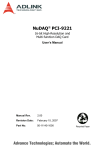
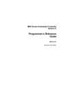
Figure 1: PowerPro Block Diagram
SDRAM - Bank 0
Buffered Writes
Buffered Reads (wait sates)
Programmable Timing
ECC Support
Bank 1
Bank 2
Bank 3
I2C
JTAG
80A600B_BK001_03
Up to four
external
bus masters
1.1.1
IEEE1149.1
Boundary
Scan
Two master-only
interfaces with up
to 8 slave devices
PowerPro Features
PowerPro features are listed in the following sub-sections.
1.1.1.1
Processor Interface
•
Direct-connect support for:
— MPC8260 (60x interface)
— PowerPC 603e, PowerPC 740, PowerPC 750,
PowerPC 7400 (60x interface)
24
•
66 to 100 MHz bus frequency
•
32-bit address, 64-bit data
•
Address and data parity
•
De-coupled address and data bus operation
PowerPro User Manual
80A5000_MA001_10
1. Functional Overview
•
Bus Slave
— 64-bit port size
— Eight programmable slave images for memory peripherals
— Programmable register image
•
Bus Arbiter
— Supports up to four external bus masters
— Two level fair arbitration scheme
— Independent address and data bus arbitration
— Programmable bus parking
— Boot control
1.1.1.2
1.1.1.3
1.1.1.4
SDRAM Interface
•
Operating at processor (60x) bus speed
•
64-bit interface for non-ECC operations
•
72-bit interface (64-bit data and 8 check-bits) for ECC applications
•
ECC protection applied to the data path
•
Page management for optimal read and write access times. The SDRAM Interface
has the ability to have 32 logical banks open simultaneously.
•
Four banks supported with two chip selects per bank, up to 1 GB per bank.
•
Programmable timing parameters per bank
•
Programmable address mappings per bank
FLASH/ROM Interface
•
Four banks of FLASH/ROM/SRAM
•
Direct support for 8-, 16-, 32-, and 64-bit external peripherals
•
Programmable timing per bank
•
64-bit packed reads for PowerPC bus accesses
•
Programmable address mappings
Integrated Peripherals
•
Dual high-speed UARTs
•
I2C Interface
•
Programmable General Purpose Timer, four compare and four trigger settings.
•
System Watchdog Timer
•
32 channel Interrupt controller, interrupts from external and internal (UART, I2C,
timers, ECC, errors) sources
PowerPro User Manual
80A5000_MA001_10
25
1. Functional Overview
1.1.1.5
•
50 General purpose I/O pins. These pins are multiplexed with other functions.
•
JTAG support for board level testing
Registers
•
1.1.1.6
Bidirectional interrupt pins (maskable/routable)
Packaging
•
376-pin HPBGA
— 23 mm body size
— 1.0 mm ball pitch
1.1.1.7
1.1.2
Operating Environment
•
Commercial
•
Industrial
PowerPro Benefits
PowerPro offers the following benefits to designers:
26
•
Modular PowerPC design
•
Increased through-put with memory system optimization
•
Proven product testing in a hardware emulation environment
•
Reduced design effort in both software and hardware PowerPC systems
•
ECC protection in PowerPC systems.
PowerPro User Manual
80A5000_MA001_10
1. Functional Overview
1.1.3
PowerPro Typical Applications
PowerPro is targeted at communications infrastructure applications that use both
PowerPC architectures, such as the following:
•
ADSL concentrators
•
CDMA base stations
•
VoIP gateways
•
Ethernet switches
•
VPN equipment
•
MPEG 2 encoders
•
Exchange carrier switching equipment
Figure 2 illustrates a typical PowerPro application involving the PowerPC 750 and
PowerSpan. In this diagram PowerPro is used in both a PowerPC and PCI system.
Figure 2: PowerPro, PowerPC and PCI Application
MPC8260
FLASH/
ROM
PowerPC
750
32-bit Data
PowerPro
Processor Bus
32-bit Address / 64-bit Data
100 MHz
PowerSpan
64-bit Data
8-bit ECC
SDRAM
PCI-2 (optional)
32-bit Address / 32-bit Data
66 MHz
PMC Connectors
PCI-1
32-bit Address / 64-bit Data
66 MHz
PCI Bus
PowerPro User Manual
80A5000_MA001_10
27
1. Functional Overview
The SDRAM and FLASH/ROM can use a shared bus, as shown in Figure 2, or they can
configured to use separate data buses. The FLASH/ROM data bus can be have a width
of 8, 16 or 32-bit (see Figure 3).
Figure 3: PowerPro, PowerPC and PCI Application With Separate FLASH/ROM and
SDRAM Data Buses
MPC8260
PowerPC
750
PowerPro
Processor Bus
32-bit Address / 64-bit Data
100 MHz
PowerSpan
8,16,or 32-bit
Data
64-bit Data
8-bit ECC
FLASH/
ROM
SDRAM
PCI-2 (optional)
32-bit Address / 32-bit Data
66 MHz
PMC Connectors
PCI-1
32-bit Address / 64-bit Data
66 MHz
PCI Bus
28
PowerPro User Manual
80A5000_MA001_10
1. Functional Overview
Figure 4 illustrates a typical PowerPro application involving the MPC8260 and the
PowerPC 750. In this diagram PowerPro is used in both a PowerPC system.
Figure 4: PowerPro PowerPC Application
FLASH/
ROM
PowerPC
750
32-bit Data
PowerPro
Processor Bus
32-bit Address / 64-bit Data
100 MHz
64-bit Data
8-bit ECC
SDRAM
Interface to
Non-PCI
System Bus
Non-PCI System Bus
PowerPro User Manual
80A5000_MA001_10
29
1. Functional Overview
1.2
Architecture
PowerPro operates in PowerPC systems and has a 64-bit, 100 MHz SDRAM Interface
that allows the PowerPC 750 and PowerPC 740 to access memory on a high-speed bus.
PowerPro also has a 64-bit Processor Bus Interface and a FLASH/ROM Interface.
The PowerPro Processor Bus Interface responds to read and write requests from
external bus masters to any of the four SDRAM memory banks, the four FLASH/ROM
memory banks, and internal registers.
Reads and writes to the Processor Bus Interface are processed in the order that they are
received by PowerPro.
PowerPro’s main architectural elements include:
•
Processor Bus (PB) Interface
— 64-bit data bus
•
Processor Bus arbiter
— Four external bus masters
— Hardware verified against PowerPC 750, PowerPC 740 and MPC8260 bus
interfaces
•
SDRAM Interface
— 64-bit data bus
— 72-bit data bus with ECC protection enabled
— 100 MHz operating frequency
— PC-100 compliant
•
FLASH/ROM Interface
— 8-,16-,32-, or 64-bit
•
Registers
— 4 byte and 8 byte reads
— 4 byte writes
•
I2C Interface
•
General Purpose I/O ports (GPIO)
•
Dual UARTs (DUART)
•
Interrupt controller
•
JTAG
The functional diagram in Figure 5 outlines the major components of the PowerPro
64-bit architecture.
30
PowerPro User Manual
80A5000_MA001_10
1. Functional Overview
Figure 5: PowerPro Dataflow Diagram
Processor (60x) Bus
Processor Bus Interface (PB)
GPIO
Registers
UART 0
Timers
Datapath
Interrupts
UART 1
SDRAM Interface
FLASH/ROM Interface
SDRAM 0
FLASH/ROM 0
SDRAM 1
FLASH/ROM 1
SDRAM 2
FLASH/ROM 2
SDRAM 3
FLASH/ROM 3
2
I C1
I2C 0
Memory Address/Control
Memory Data
Each of these major blocks are discussed in the following sections. For more detailed
information, refer to specific chapters in this manual.
Note
PowerPro User Manual
80A5000_MA001_10
Not all PowerPro functionality is available at one time. Many of the
functions on PowerPro are multiplexed. Refer to 13. “Signals and Pinout”
on page 161 and 14. “Electrical Characteristics” on page 179 for more
information on multiplexed functionality.
31
1. Functional Overview
1.2.1
Processor Bus (PB) Interface
PowerPro has a Processor Bus Interface that directly connects to a variety of PowerPC
microprocessors. PowerPro supports the following PowerPC microprocessors:
MPC8260 (PowerQUICC II), PowerPC 603e, PowerPC 740, PowerPC 750 and
PowerPC 400. The PB Interface operates at 100 MHz in PowerPC 740 and
PowerPC 750 applications.
The PB Interface has a 32-bit address bus and 64-bit data bus. It is a slave only interface
and supports single-beat and burst data transfers. The address and data buses are
decoupled for pipelined transactions, and also support MPC8260 extended cycles.
Extended cycles on the MPC8260 offers more flexible bursting and more efficient use
of the processor bandwidth.
The PowerPro PB Interface is connected to the processor (60x) bus. Please refer to
Motorola documentation for specific information on the processor (60x) bus and its
requirements.
For more information on the PB Interface, refer to 2. “Processor Bus Interface”
on page 35.
1.2.1.1
Processor Bus Arbitration
The PB Interface has an integrated bus arbiter. The arbiter supports four external bus
masters for applications involving multiple bus masters.
The PB arbiter implements two levels of priority. Devices programmed into a specific
priority level operate in a round robin fashion. Each master has a register to determine
its arbitration level for the address bus. The arbitration level for each master is
programmable.
1.2.2
SDRAM Interface
PowerPro provides control functions and signals for JEDEC-compliant SDRAM
devices.
PowerPro enables access to four (single or dual) DIMMs of SDRAM with two chip
selects per DIMM. Both buffered (registered) and non-buffered DIMMs are supported.
PowerPro has a maximum of 4 GB of addressable SDRAM memory. All SDRAM
parameters are selectable per bank, which allows each DIMM socket to contain a
different variety of SDRAM. This capability gives each SDRAM optimized timing
parameters.
For more information on the SDRAM Interface, refer to 4. “SDRAM Interface”
on page 75.
1.2.2.1
32
ECC Protection
ECC protection is an alternative to simple parity detection. PowerPro offers ECC
protection for the data path between PowerPro and system memory. ECC detects errors,
and corrects single-bit errors in the 64-bit data path.
PowerPro User Manual
80A5000_MA001_10
1. Functional Overview
1.2.3
FLASH/ROM Interface
PowerPro supports four distinct banks of FLASH/ROM devices. The FLASH/ROM
devices can either share the SDRAM data bus or have a single, dedicated 8-bit data bus.
When the FLASH/ROM Interface shares the SDRAM data bus, the width of the bus can
be configured as 8-, 16-, 32-, or 64-bit.
The FLASH/ROM Interface is a flexible interface with many multiplexing options to
support a variety of address and data bus requirements.
Each of the four independent FLASH/ROM banks have individually programmable
address images. Individual, internal chip-select machines drive each of the four
FLASH/ROM banks. The chip-select machines arbitrate for required resources. This
ability provides flexible system functionality.
For more information on the FLASH/ROM Interface, refer to 3. “FLASH/ROM
Interface” on page 53.
1.2.4
Registers
The 512 byte control and status registers are used to program device specific
parameters, as well as monitor settings. All registers are 32-bit and are accessible by
external masters through the PB Interface. Register accesses can either be 4 or 8 bytes.
For more information on registers, refer to 16. “Registers” on page 199.
1.2.5
I2C Interface
PowerPro contains two master-only, I2C bus compatible interfaces. Each interface
supports up to eight I2C slave devices.
The I2C Interfaces are connected to serial presence detect EEPROMs; these are
commonly found on DIMM modules.
In a system that contains both PowerSpan and PowerPro, the same EEPROM can be
shared between the two devices.
For more information on the I2C Interface, refer to 7. “I2C Interface” on page 115.
1.2.6
General Purpose I/O Port
PowerPro has flexible general purpose I/O capability. Although all PowerPro pins are
programmed with a primary purpose, in many instances these pins are not enabled
because their functionality is not required in the system. These unused pins are assigned
to the General Purpose I/O (GPIO) pool. All pins capable of GPIO are mapped in a
GPIO register.
The GPIO port, combined with the general purpose timers available on PowerPro,
enable software to control any low to medium speed device that is not time critical.
For more information on the GPIO Port, refer to 6. “General Purpose I/O Interface”
on page 111.
PowerPro User Manual
80A5000_MA001_10
33
1. Functional Overview
1.2.7
UART Interface
PowerPro has two, serial universal asynchronous receiver transmitter (UART) protocol
interfaces. These dual UARTs complete parallel-to-serial conversion of digital data
which must be transmitted, and complete the serial-to-parallel conversion of digital data
which has been transmitted.
For more information on the UART Interface, refer to 5. “Dual UART Interface”
on page 105.
1.2.8
JTAG Interface
PowerPro has a Joint Test Action Group (JTAG) Interface to facilitate boundary-scan
testing. The JTAG Interface implements the five test port signals required to be fully
compliant with IEEE 1449.1 specification. Refer to the IEEE 1449.1 Boundary-scan
Specification for more information.
For more information on the JTAG Interface, refer to 12. “JTAG Interface”
on page 157.
34
PowerPro User Manual
80A5000_MA001_10
2. Processor Bus Interface
This chapter outlines the functionality of the Processor Bus Interface. The following
topics are discussed:
2.1
•
“Processor Bus Interface” on page 36
•
“Processor Bus Interface Arbitration” on page 49
•
“Endian Conversion” on page 52
Overview
The PowerPro Processor Bus (PB) Interface is a slave only interface. The PB
Interface data width is 64-bit and the address width is 32-bit. The maximum
operating frequency is 100 MHz.
2.1.1
Interface Support
The PB Interface is specifically designed to support the following PowerPC
devices:
•
MPC8260 (PowerQUICC II)
•
PowerPC 603e/740/750
•
PowerPC 7400
The MPC8260 and the PowerPC 7400 must operate in processor (60x)
compatible bus mode to be used in systems. The MPC8260 has the
option to operate in Single MPC8260 bus mode; PowerPro does not
support this mode. The MPC7400 has the option to operate in MPX
mode; PowerPro does not support this mode.
PowerPro User Manual
80A5000_MA001_10
35
2. Processor Bus Interface
The supported PowerPC processor interfaces are not identical. However, the PB
Interface discusses the processor (60x) bus protocol used by all the supported
processors. The following sections highlight how PowerPro operates differently to
address specific processor requirements. An example of different operation in
PowerPC devices is the extended cycles with the MPC8260.
2.1.2
Terms
The following terms are used in the PB Interface description.
•
Address retry window: This term refers to the clock following the assertion of
PB_AACK_. It is the latest cycle that a snooping master can request for an
address tenure re-run.
•
Window of opportunity: This term refers to the clock following the assertion
of PB_ARTRY_. The retrying master must request the bus on this clock to
ensure that it is the next bus owner. This allows it to perform the transactions
required to maintain cache coherency.
2.2
Processor Bus Interface
2.2.1
Overview
The PowerPro PB Slave Interface claims processor (60x) bus transactions intended
for the SDRAM Interface, FLASH/ROM Interface, or the PowerPro internal control
and status registers. The slave claims the transactions based on the address decode
information in PowerPro. Refer to “Address Decoding” on page 37 for information
on base address registers that are programmed in PowerPro.
2.2.2
PowerPro as PB Slave
The operation of the PB Slave Interface is described by dividing the PB slave
transaction into three different phases:
•
36
Address Phase: This section discusses the decoding of processor (60x) bus
accesses.
PowerPro User Manual
80A5000_MA001_10
2. Processor Bus Interface
•
Data Phase: This section describes control of transaction length.
•
Terminations: This section describes the terminations supported by PowerPro,
as well as exception handling.
A pull-up resistor is required on PB_A[7] when PowerPro is operating
as Configuration Master but resistors are not required on the remaining
processor bus address (PB_A[0:31]) and data (PB_D[0:63]) signals to
guarantee functional operation of PowerPro. However, adding resistors
to the other address and data signals minimizes the current drawn by
PowerPro's tristated buffers when the bus is in an idle condition. The
system designer must decide whether to add these resistors to the
address bus and data bus.
2.2.3
Address Phase
2.2.3.1
Address Decoding
A PB slave image is the range of PB physical address space used to decode a
PowerPro access. A slave image is controlled by the information programmed in the
base address registers. Each slave image monitors the Processor Bus Base Address
(PB_REG_ADDR) register (see page 208). When the address falls into the
configured address range, and the Processor Bus Transfer Type (PB_TT) is
supported, PowerPro claims the address tenure. See “Transaction Types” on page 38
for more information on supported transaction types.
PowerPro has the following slave (address) images:
•
“PB Register Base Address” on page 208
•
“SDRAM Memory Bank x Address” on page 233
•
“ROM Memory Bank x Address” on page 242
The “x” symbol in the register naming indicates that there are various images for
both the SDRAM slave images and FLASH/ROM slave images. The PB slave
supports four SDRAM slave images and four FLASH/ROM slave images. The PB
slave supports one register image. Refer to 16. “Registers” on page 199 for more
information on register access through the PB Interface.
A single dedicated address image can be connected to the general
purpose timer trigger, or an interrupt, for debugging purposes. When
the selected address appears on the processor (60x) bus the event is
logged. This is independent of whether or not the address was destined
for PowerPro. See 8. “Timers” on page 119 and 10. “Interrupt
Controller” on page 135 for more information.
PowerPro User Manual
80A5000_MA001_10
37
2. Processor Bus Interface
2.2.3.2
2.2.3.3
Claiming Transactions
The PB slave image claims transactions only under the following circumstances:
•
the address falls into the configured slave image
•
the transaction type is supported by PowerPro
Transaction Types
The PB slave only claims processor (60x) bus transactions with specific transaction
types. The supported transaction types consist of address only, read, and write.
These transaction types, and their binary codes, are described in Table 1.
PowerPro registers only accept single read cycles and single write
cycles.
38
PowerPro User Manual
80A5000_MA001_10
2. Processor Bus Interface
Address only transfer types are claimed to ensure PowerPro does not negatively
impact cache control, reservation or ordering transactions on the processor (60x)
bus. PowerPro handles address only cycles by asserting PB_AACK_ — no data
transfer occurs.
Table 1: PowerPro PB Slave Transaction Types
PB_TT[0:4]
Name
Address only
00000
Clean Block
00100
Flush Block
01000
Sync Block
01100
Kill Block
10000
eieio
11000
tlb invalidate
00001
lwarx
01001
tlb sync
01101
icbi
Read
01010
Read
01110
Read with intent to modify
11010
Read Atomic
11110
Read with intent to modify atomic
01011
Read with no intent to cache
Write
00010
Write with flush
00110
Write with kill
10010
Write with flush atomic
Since PowerPro does not have a cache, all read and write transfer types are treated
the same. For example, a “Read with intent to modify” (PB_TT= 01110) is handled
the same way as a “Read Atomic” (PB_TT= 11010).
PowerPro User Manual
80A5000_MA001_10
39
2. Processor Bus Interface
2.2.3.4
Address Tenure
The processor bus has independent address and data tenures to support pipelined
transactions. PowerPro operates in systems with up to one level of address
pipelining. PowerPro requires that data tenures be kept in strict order with respect to
address tenures.
Each slave in a processor (60x) bus system is responsible for the following actions:
•
decoding the address broadcast by the master
•
claiming the address tenure with the assertion of Address Acknowledge
(PB_AACK_)
•
managing the data termination signals during the data tenure
Address Acknowledge (PB_AACK_)
The PB slave uses PB_AACK_ to limit the level of address pipelining to one. The
PB slave does not acknowledge subsequent address phases until it finishes its
participation in the current data tenure. If the previous address phase was claimed
by another slave, the PB slave does not acknowledge the current address phase until
the previous slave completes its data tenure.
The earliest time that the PB Slave Interface asserts PB_AACK_ is two clocks after
the Processor Bus Transfer Start (PB_TS_) signal is asserted low. This signal
indicates the beginning of a new address bus tenure. The PB slave can also delay the
assertion of PB_AACK_ in order to wait for external memory devices to access
data.
Address Retry (PB_ARTRY_)
The PowerPro PB Slave Interface uses the Address Retry Enable (ARTRY_EN) bit,
in the PB_GEN_CTRL register (see page 209), to control its use of PB_ARTRY_
during transactions. By default, the use of address retry is disabled. The PB slave
supports a single read at a time when ARTRY_EN is disabled.
PB_ARTRY_ is never asserted in SDRAM accesses, but may be asserted (if
enabled) in FLASH/ROM accesses. When ARTRY_EN is enabled, the PB slave
retries a processor (60x) bus master under the following conditions:
•
FLASH/ROM read when the transaction will take more than eight clocks
•
FLASH/ROM write when the ROM machine is busy
When the assertion of PB_ARTRY_ is enabled, PB_ARTRY_ is only asserted the
clock after PB_AACK_. This constraint places the assertion of the signal within the
address retry window.
40
PowerPro User Manual
80A5000_MA001_10
2. Processor Bus Interface
When PB_ARTRY_ is disabled — by setting the ARTRY_EN bit to 0 — the PB
slave holds onto the bus after the assertion of PB_AACK_ until it is able to assert
Processor Bus Transfer Acknowledge (PB_TA). The PB Slave acknowledges the
address tenure with the PB_AACK_ signal and captures the address in the Delayed
Read latch. The Delayed Read Request latch is de-allocated when the external
processor (60x) bus master completes the transaction.
2.2.3.5
Address Parity
Address parity checking is supplied on each byte of the address bus. Parity is
disabled on PowerPro by default.
Address parity bit assignments are defined in Table 2.
Table 2: PowerPro PB Address Parity Assignments
Address Bus
Address Parity
PB_A[0:7]
PB_AP[0]
PB_A[8:15]
PB_AP[1]
PB_A[16:23]
PB_AP[2]
PB_A[24:31]
PB_AP[3]
When the PB slave detects an address parity error during its decode process it does
not assert Address Acknowledge (PB_AACK_). Address Parity checking is enabled
when the Address Parity Enable (AP_EN) bit is set in the PB_GEN_CTRL register
(see page 209).
Even or odd parity is configured with the Parity (PARITY) bit in the
PB_GEN_CTRL register.
2.2.4
Data Phase
2.2.4.1
Data Tenure
The processor (60x) bus protocol has independent address and data tenures to
support pipelined transactions. PowerPro operates in systems with up to one level of
address pipelining. PowerPro requires that data tenures be kept in strict order with
respect to address tenures.
PowerPro User Manual
80A5000_MA001_10
41
2. Processor Bus Interface
2.2.4.2
Transaction Length
The PB slave supports a super-set of the data transfer sizes supported by the
embedded PowerPC family. All data transfer sizes supported by the PB slave are
illustrated in Table 3. Burst transfers are indicated by the assertion of Processor Bus
Transfer Burst (PB_TBST_). The shaded regions indicate transaction sizes unique
to the MPC8260.
Table 3: PowerPro PB Transfer Sizes
Transfer Size
Bytes
PB_TBST_
PB_TSIZ[0]
PB_TSIZ[1:3]
Byte
1
1
0
001
Half-word
2
1
0
010
Tri-byte
3
1
0
011
Word
4
1
0
100
Five bytes
5
1
0
101
Six bytes
6
1
0
110
Seven bytes
7
1
0
111
Double Word (DW)
8
1
0
000
Extended Double (MPC8260 only)
16
1
1
001
Extended Triple (MPC8260 only)
24
1
1
010
Burst (Quad DW)
32
0
0
010
2.2.4.3
Data Alignment
The PowerPro port size is 64-bit. Embedded processor (60x) bus transfer sizes and
alignments, as defined in Table 3 and Table 4, are supported by the PB Interface for
transaction accesses. PowerPro register accesses must be 8 bytes or less.
Register accesses are usually restricted to 4 byte (32-bit) accesses. Any
accesses larger than 4 bytes normally results in an error condition and
the assertion of the Processor Bus Transaction Error Acknowledge
(PB_TEA_) signal when PB_TEA_ generation is enabled in PowerPro.
PowerPro allows 8 byte register accesses for systems that require
8 byte register reads, but the PB_TEA_ signal must be disabled in the
TEA_EN bit, in the PB_GEN_CTRL register (see page 209).
42
PowerPro User Manual
80A5000_MA001_10
2. Processor Bus Interface
The size of the register access is controlled with the Vector Increment field, in the
Interrupt Vector Increment register (see page 289). The VINC[1] bit controls upperword register access. When PB_TEA_ generation is disabled in PowerPro, an 8 byte
register read returns the 4 byte register addressed repeated in the lower and upper
word. When VINC[1] is set to 0 and an 8 byte read is performed, the register at
offset (PB_REG_ADDR & 0xFF8) is returned (32-bit value) copied in the upper
and lower 32-bit words. When VINC[1] is set to 1 and an 8-byte read is performed,
the register at offset (PB_REG_ADDR & 0xff8) + 0x004 is returned (32-bit value)
replicated in the upper and lower 32-bit words.
For example, an 8 byte read to REG_BADDR + 0x198 when VINC[1] is set to 0
returns the address {INT_VBADDR, INT_VBADDR}. An 8-byte read to
REG_BADDR + 0x198 when VINC[1] is set to 1 returns address {INT_MISC,
INT_MISC}. The TEA_EN bit, in the PB_GEN_CTRL register (see page 209),
must be 0 in this mode. This setting disables the assertion of PB_TEA_ when a
register access exceeds 4 bytes. Table 4 lists the size and alignment of transactions
less than or equal to 8 bytes.
The information in Table 4 is independent of endian considerations
and refers to byte lane control on the PB Interface.
Table 4: PowerPro PB Single Beat Data Transfers
Size
TSIZ[0:3]
A[29:31]
Data Bus Byte Lanes
0
Byte
0001
000
0001
001
0001
010
0001
011
0001
100
0001
101
0001
110
0001
111
PowerPro User Manual
80A5000_MA001_10
1
2
3
4
5
6
7
D0
D1
D2
D3
D4
D5
D6
D7
43
2. Processor Bus Interface
Table 4: PowerPro PB Single Beat Data Transfers
Size
TSIZ[0:3]
A[29:31]
Half word
0010
000
0010
001
0010
010
0010
100
0010
101
0010
110
0011
000
0011
001
0011
100
0011
101
0100
000
0100
100
0101
000
0101
011
0110
000
0110
010
0111
000
0111
001
0000
000
Tri-byte
Word
Five bytes
Six bytes
Seven bytes
Double word
2.2.4.4
Data Bus Byte Lanes
D0
D1
D1
D2
D2
D3
D4
D5
D5
D6
D6
D0
D1
D2
D1
D2
D3
D4
D0
D1
D2
D0
D0
D0
D1
D6
D5
D6
D7
D5
D6
D7
D6
D7
D7
D3
D4
D3
D4
D5
D2
D3
D4
D5
D2
D3
D4
D5
D6
D1
D2
D3
D4
D5
D6
D1
D2
D3
D4
D5
D6
D7
D1
D2
D3
D4
D5
D6
D7
D1
D2
D5
D3
D4
D0
D7
Cache Line Size
The supported set of embedded PowerPC processors implement a 32-byte cache
line size. Cache wrap reads are supported by the PB slave for burst and extended
transactions.
PowerPC processors do not generate cache wrap writes.
44
PowerPro User Manual
80A5000_MA001_10
2. Processor Bus Interface
2.2.4.5
Reads
All PB Slave reads can be retried if the Address Retry Enable (ARTRY_EN) bit is
set in the PB_GEN_CTRL register (see Table 43 on page 209).
Address retries are applicable to FLASH/ROM reads and are not
applicable to SDRAM reads.
Retried Reads
An outstanding read is referred to as a retried read. The following steps outline what
occurs during a read request:
1. Delayed Read Request: The PB slave latches transaction parameters and issues
a retry (PB_ARTRY_).
2. Delayed Read Completion: The PB slave obtains the requested data and
completion status on the destination bus.
3. Read Completion: The master repeats the transaction with the same parameters
used for the initial request.
Any attempt by a PB master to complete the read transaction is retried by the
PowerPro PB slave when PB_ARTRY_ is enabled.
Address Retry (PB_ARTRY_)
For more information refer to “Address Retry (PB_ARTRY_)” on page 40.
2.2.4.6
Writes
Write data is treated independently from read data. A write to an image does not
invalidate the contents of the read line buffer currently in use.
2.2.4.7
Data Parity
Data Parity is enabled by setting the Data Parity Enable (DP_EN) bit in the
PB_GEN_CTRL register (see page 209). Even or odd parity is enabled by setting
the Parity (PARITY) bit in the same register.
Parity generation and checking is provided for each byte of the data bus and for
each data beat of the data tenure. Parity checking is disabled by default.
Enabling data parity with the DP_EN enables both parity checking and
generation. However, if systems require independent parity checking
and generation, parity checking can be disabled in the DP_CHK bit with
an additional register write.
PowerPro User Manual
80A5000_MA001_10
45
2. Processor Bus Interface
Data parity bit assignments are defined in Table 5.
Table 5: PowerPro PB Data Parity Assignments
Data Bus
Data Parity
PB_D[0:7]
PB_DP[0]
PB_D[8:15]
PB_DP[1]
PB_D[16:23]
PB_DP[2]
PB_D[24:31]
PB_DP[3]
PB_D[32:39]
PB_DP[4]
PB_D[40:47]
PB_DP[5]
PB_D[48:55]
PB_DP[6]
PB_D[56:63]
PB_DP[7]
The data parity bits, PB_DP[0:7], are driven to the correct values for even or odd
parity by the PB slave during reads. When checking is enabled, the data parity bits,
PB_DP[0:7], are checked by the PB slave during writes.
The detection of a data parity error does not affect the transaction. Data is still
forwarded to the destination. For more information on PB Interface errors refer to 9.
“Error Handling” on page 123.
2.2.5
Termination
The PB Interface uses the following signals to indicate termination of individual
data beats and/or data tenures:
46
•
PB_ARTRY_: This signal terminates the entire data tenure and schedules the
transaction to be retried. No data is transferred, even if the signal is asserted at
the same time as PB_TA_ or Processor Bus data Valid (PB_DVAL_).
•
PB_TA_: This signal is asserted by the PB slave to indicate the successful
transfer of a single beat transaction, or each 8-byte quantity transferred for a
burst.
PowerPro User Manual
80A5000_MA001_10
2. Processor Bus Interface
•
PB_DVAL_: This signal is asserted by the PB slave to indicate the successful
transfer of an 8 byte quantity within an extended transfer of 16 or 24 bytes.
PB_TA_ is asserted with PB_DVAL_ on the transfer of the last 8 byte quantity.
The PB slave does not use PB_TA_, or PB_DVAL_ to insert wait states.
•
PB_TEA_: This signal indicates an unrecoverable error and causes the external
master to immediately terminate the data tenure.
The PB Slave does not assert a data termination signal earlier than the
address retry window.
2.2.5.1
Assertion of PB_TEA_
The assertion of PB_TEA_ can be enabled or disabled through the Transaction
Error Acknowledge (TEA_EN) bit in the PB_GEN_CTRL register (see page 209).
In a development environment, the TEA_EN bit can be set in order to enable the
assertion of PB_TEA_ to assist with software debugging. In a production
environment, it can be useful to disable the TEA_EN bit. When PB_TEA_ is
disabled, the PB_TA_ signal is asserted in its place.
When PB_TEA_ is disabled, incorrect data can be transferred in a
system.
When a particular slave image cannot manage transactions involving more than 4
bytes, PowerPro asserts PB_TEA_. An example of the assertion of PB_TEA_ for
unsupported reads is register accesses that exceed 4 bytes.
2.2.5.2
Processor Bus WatchDog Timer
PowerPro uses a watchdog timer to monitor the processor (60x) bus. The Processor
Bus Watchdog register (see page 261) uses the setting that is programmed in the
COUNT field to observe the processor (60x) bus. If the internal processor (60x) bus
counter reaches the value programmed in COUNT, the signals PB_TA_,
PB_AACK_, PB_TEA_, and PB_DVAL_ are asserted when they are enabled.
In order for the PB_TA_, PB_AACK_, PB_TEA_, and PB_DVAL_ to be asserted
when the internal processor (60x) bus counter reaches the value programmed in
COUNT, the following PB_GEN_CTRL register bits (see page 209) must be set to
1:
•
WATCH_TA: Assert PB_TA_ when the watchdog timer expires
•
WATCH_DVAL: Assert PB_DVAL_ when the watchdog timer expires
•
WATCH_TEA: Assert PB_TEA_ when the watchdog timer expires
•
WATCH_AACK: Assert PB_AACK_ when the watchdog timer expires
PowerPro User Manual
80A5000_MA001_10
47
2. Processor Bus Interface
Figure 6 illustrates a transaction that has a programmed COUNT value of 80 system
clocks. A transaction starts at 3345ns with the assertion of PB_TS_ and an address
of 32’h8706BBB8.
The address 32’h8706BBB8 used in Figure 6 has no corresponding
system bus slave. Therefore no device should claim the transaction, so
the bus would normally enter a stalemate condition. It is only used as an
example.
After the system clock reaches 83 clocks after the start of the transaction (the
vertical cursors in Figure 6, starting at 3345ns and ending at 4175ns, mark the 830ns
that represent the 83 system clock cycles), PowerPro claims the transaction by
asserting PB_TA, PB_AACK, PB_DVAL and PB_TEA all on the same clock.
PowerPro asserted these signals because the WATCH_AACK, WATCH_TEA,
WATCH_DVAL, and WATCH_TA bits in the PB_GEN_CTRL register where set to
1.
Figure 6: Count Programmed to 80 System Clocks
Cursor1 = 3345 ns
Cursor2 = 4175 ns
PB_CLK = 1
PB_A[0:31] = ’h 8706BBB8 F* F* * FF* 8706BBB8
PB_TS_ = 0
PB_TBST_ = 0
4
4
2
PB_TSIZ[0:3] = ’h 2
02 *
02
PB_TT[0:4] = ’h 02
PB_AACK_ = 1
PB_ARTRY_ = 1
* *
BC4FB7E72DA8E227
PB_D[0:63] = ’h zzzzzzzz zzzzzzzz
PB_TA_ = 1
PB_DVAL_ = 1
PB_TEA_ = 1
WATCHDOGoCOUNT[0:31] = ’d 80 429496* 80
WATCH_AACK = 1
WATCH_DVAL = 1
WATCH_TA = 1
WATCH_TEA = 1
F*
WatchDog Timer During an Address Only Transaction
In Figure 7 a transaction is started that is an Address Only cycle. PowerPro is a
slave device and does not respond with a data bus assertion. PowerPro, in this case,
only asserts PB_AACK even though the WATCH_TEA, WATCH_DVAL, and
WATCH_TA bits are programmed to 1.
48
PowerPro User Manual
80A5000_MA001_10
2. Processor Bus Interface
Figure 7: Count Programmed to 80 System Clocks During an Address Only Transaction
Cursor1 = 3345 ns
Cursor2 = 4175 ns
PB_CLK = 1
PB_A[0:31] = ’h 8706BBB8 F* F* * FF* 8706BBB8
PB_TS_ = 0
PB_TBST_ = 0
4
4
2
PB_TSIZ[0:3] = ’h 2
PB_TT[0:4] = ’h 00
02 *
00
PB_AACK_ = 1
PB_ARTRY_ = 1
PB_D[0:63] = ’h zzzzzzzz zzzzzzzz
* *
PB_TA_ = 1
PB_DVAL_ = 1
PB_TEA_ = 1
WATCHDOGoCOUNT[0:31] = ’d 80 429496* 80
WATCH_AACK = 1
WATCH_DVAL = 1
WATCH_TA = 1
WATCH_TEA = 1
2.2.5.3
F*
Errors
The PowerPro PB Slave Interface detects the following error conditions:
•
address parity
•
data parity on writes
•
illegal accesses
See 9. “Error Handling” on page 123 and 10. “Interrupt Controller” on page 135 for
more information.
2.3
Processor Bus Interface Arbitration
The PowerPro PB arbiter supports requests for address bus and data bus ownership
from four external masters. The PB arbiter is enabled or disabled through the
External Master x Enable (Mx_EN) bit in the Processor Bus Arbiter Control
(PB_ARB_CTRL) register (see page 214). The ability to disable the internal
PowerPro arbiter makes it possible to use an external arbiter in a PowerPro system.
All PowerPro arbitration signals are multiplexed with other device
functionality. Refer to “Processor Bus Signals” on page 162 and
“Multiplexed Processor Bus Signals” on page 183 for more
information.
PowerPro User Manual
80A5000_MA001_10
49
2. Processor Bus Interface
The PB arbiter implements two levels of priority. Devices programmed into a
specific priority level operate in a round robin fashion. Each master has a External
Master x Priority Level (Mx_PRI) bit in the PB_ARB_CTRL register to determine
its arbitration level for the address bus. The arbitration level for each master can be
reconfigured during system run-time.
Figure 8 illustrates the arbitration system used in the PB Interface arbiter.
Figure 8: PB Arbitration Order
Master B
Master C
Level 1
Master A
Level 0
Arbitration Order
Level 1, Level 1, Level 1, Level 0
For example, if all bus masters
assert Request:
* A, B, C, X
* A, B, C, Y
* A, B, C, Z
* A, B, C, X
Master Z
Master X
Level 0
Master Y
50
PowerPro User Manual
80A5000_MA001_10
2. Processor Bus Interface
2.3.1
Data Bus Arbitration
The arbiter samples PB_TT[3] when PB_TS_ is asserted to generate data bus
requests. The arbiter grants the data bus to the current address bus owner by
asserting PB_DBG_ the clock after PB_TS_ is asserted. The current data bus grant
is negated when the requesting master has qualified the grant.
The Processor Bus Data Bus Grant (PB_DBG_) signals are asserted under the
following conditions:
•
The assertion of the Processor Bus Request (PB_REQ_) signal when the bus is
idle.
•
After the assertion of the Processor Bus Transaction Start (PB_TS_) signal, the
PB_DBG_ signal changes to the next requesting master or the parked master.
Requesting masters are required to qualify bus grants before
beginning a data tenure, if the 7400_MODE bit in the
PB_ARB_CTRL is set to 0.
The MPC8260 and other processor (60x) bus agents require the system signal
DBB_ to qualify data bus grants. The PowerPro PB Master does not require DBB_
to qualify data bus grants.
2.3.1.1
PB Arbiter Qualifies Bus Grants
Some processors, specifically the MPC7400, must have the data bus grant qualified
by the arbiter before it is issued to the master. PowerPro is set to PowerPC 7400
arbitration mode by default. PowerPro is set to PowerPC 7400 arbitration mode
through the 7400_MODE bit in the PB_ARB_CTRL. See section “PB Arbiter
Qualifies Bus Grants” on page 51 for more information. When PowerPro is
configured not to qualify bus grants by the PB arbiter, the requesting master must
qualify bus grants before beginning a data tenure.
2.3.2
Address Arbitration
Requesting bus masters are required to qualify bus grants before beginning an
address tenure. Some processor (60x) bus agents, including the MPC8260, require
the system signal ABB_ to qualify address bus grants. The PowerPro PB Interface
does not require ABB_ to qualify address bus grants.
2.3.2.1
Address-Only Cycles
The arbiter supports address only cycles. When PB_TT[3] is sampled low during
PB_TS_, the arbiter does not grant the data bus.
The use of PB_TT[3] as a data bus request means that the PowerPro arbiter does not
support the PowerPC instructions eciwx and ecowx.
PowerPro User Manual
80A5000_MA001_10
51
2. Processor Bus Interface
2.3.3
Delay Sampling of Transaction Start Signal
The PB arbiter can be programmed to sample requests two clocks after the PB_TS_
signals is asserted. The arbiter is programmed through the TS_DLY bit in the
Processor Bus Arbiter Control register.
An example application for this feature is the MPC8260 L2 cache, which holds its
BR_ signal after the TS_ signal starts. The PB Arbiter could see this as an additional
valid request and therefore gives the bus to the L2 cache even though the bus was
not actually requested. This bit delays when the PB arbiter samples the signal so a
false bus request is not granted.
2.3.4
Bus Parking
The PowerPro PB arbiter offers a flexible address bus parking scheme. When there
is no master requesting the address bus, the arbiter can park on either the last bus
master or a specific bus master.
The bus parking mode is determined by the Bus Park Mode (PARK) bit, in the
Processor Bus Arbiter Control (PB_ARB_CTRL) register (see page 214). To park
the bus on a specific master, the Bus Master to be Parked (BM_PARK) field in the
PB_ARB_CTRL register must be set to the specific bus master for address parking.
Table 6 shows the codes for parking external bus masters.
Table 6: Parked PB Master
BM_PARK [1:0]
Parked PB Master
External Pins
00
M0
PB_BR[0]_/PB_BG[0]_
01
M1
PB_BR[1]_/PB_BG[1]_
10
M2
PB_BR[2]_/PB_BG[2]_
11
M3
PB_BR[3]_/PB_BG[3]_
The parked master does not drive any address bus signals until it
generates a request to use the address bus.
2.4
Endian Conversion
PowerPro does not perform any endian conversion. PowerPC big-endian bit
ordering is assumed for all transactions.
52
PowerPro User Manual
80A5000_MA001_10
3. FLASH/ROM Interface
This chapter discusses the functions of the FLASH/ROM Interface. The topics
addressed in this chapter include:
3.1
•
“FLASH/ROM Signals” on page 54
•
“Address Mapping” on page 60
•
“Transactions” on page 67
•
“Connecting FLASH/ROM to PowerPro” on page 69
Overview
PowerPro supports four distinct banks of FLASH/ROM devices. The interface
enables many multiplexing options to support a variety of address and data bus
requirements. Each of the four independent FLASH/ROM banks have individually
programmable address images. FLASH/ROM devices of 8-, 16-, 32-, and 64-bit
data widths can be attached to the SDRAM data bus. Alternatively, a separate 8-bit
data bus can be used either to attach a FLASH/ROM data path or as extra address
lines
Each FLASH/ROM bank has an individually programmable image with unique
address ranges, bus widths, addressing modes and timing parameters. The
programmable images have separate parameters and an internal separate machine to
drive the image. There are four chip selects; each of the four chip-select machines
arbitrates for required resources.
When this document discusses FLASH/ROM transactions it is
referring to all ROM-like devices with asynchronous or synchronous
interfaces including FLASH, EEPROM, and SRAM.
PowerPro User Manual
80A5000_MA001_10
53
3. FLASH/ROM Interface
3.2
Changing the Configuration of a FLASH/ROM
Bank
When the configuration used on a FLASH/ROM bank must be changed when the
system is active, the bank must first be disabled. After the bank is disabled, then the
PER_Bx_CTRL register can be modified. The bank is re-activated only after the
PER_Bx_CTRL register is modified.
Changing the configuration of a FLASH/ROM bank can be performed
while a read is in progress to the bank, but not while a write is in
progress to the bank. If the configuration is changed while a write is in
progress the rest of the write executes with the new parameters.
The following steps show how to change the configuration of a FLASH/ROM bank.
1. Set the ENABLE bit of the FLASH/ROM bank
–
PER_Bx_ADDR[31] = 0
2. Modify the PER_Bx_CTRL register
3. Set the ENABLE bit of the FLASH/ROM bank
— PER_Bx_ADDR[31] = 1
3.3
FLASH/ROM Signals
FLASH/ROM memory space is separate from SDRAM memory space. The
FLASH/ROM chip selects activate the appropriate FLASH/ROM bank when the
address falls within one of the FLASH/ROM address ranges.
54
PowerPro User Manual
80A5000_MA001_10
3. FLASH/ROM Interface
Table 7 shows the FLASH/ROM Interface signals.
Table 7: FLASH/ROM Interface Signals
Pin Name
Pin Type
Description
SD_A[12:0]
Output
1. SDRAM Address
Multiplexed
with:
2. EEPROM Address
EE_A[12:0]
SD_BA[1:0]
Output
Multiplexed
with:
1. SDRAM Bank Address
2. EEPROM Address
EE_A[14:13]
SD_SELECT
Multiplexed
with:
Tristate
bidirectional
1. SDRAM Bank Select: External FET switch
2. EEPROM Buffer Select
• EE_SELECT
4. EEPROM Address Latch 0: For time-multiplexing the EEPROM
address, the first address phase is latched qualified with this signal
• EE_AL[0]/
3. General Purpose I/O
• GPIO[23]
EE_AL1_
Multiplexed
with:
Tristate
bidirectional
1. EEPROM Address Latch 1: For time-multiplexing the EEPROM
address, the second address phase is latched qualified with this signal
2. General Purpose I/O.
GPIO[24]
EE_OE_
Multiplexed
with:
Tristate
bidirectional
1. External Memory Output Enable
Tristate
bidirectional
1. External Memory Write Enable
2. General Purpose I/O
GPIO[25]
EE_WE_
Multiplexed
with:
2. General Purpose I/O
GPIO[26]
PowerPro User Manual
80A5000_MA001_10
55
3. FLASH/ROM Interface
Table 7: FLASH/ROM Interface Signals
Pin Name
Pin Type
Description
EE_RNW
Tristate
bidirectional
1. EEPROM Read not Write: Active 1 during an EEPROM read, 0 at all
other times.
Multiplexed
with:
2. General Purpose I/O
GPIO[27]
EE_AL2
Multiplexed
with:
Tristate
bidirectional
1. EEPROM Address Latch 2: For time-multiplexing the EEPROM
address, the third address phase is to be latched qualified with this signal.
2. General Purpose I/O
GPIO[28]_
EE_READY
Multiplexed
with:
Tristate
bidirectional
1. External Memory Ready Input Indicator: Tells PowerPro when FLASH
is ready on the data bus so PowerPro knows when to sample it.
2. General Purpose I/O
GPIO[29]
EE_CS[0:3]_
Multiplexed
with:
Tristate
bidirectional
1. External Memory Chip Select: One per bank.
2. General Purpose I/O
GPIO[30:33]
56
PowerPro User Manual
80A5000_MA001_10
3. FLASH/ROM Interface
Table 7: FLASH/ROM Interface Signals
Pin Name
Pin Type
Description
EE_DATA[0:7]
Tristate
bidirectional
1. ROM Data [0:7]
Multiplexed
with:
2. ROM upper (MSB) address bits [23:15]
3. ROM address bits [31:24] (time-multiplexed)
• EE_A[23:15]
4. ROM address bits [23:16] (time-multiplexed)
• EE_A[31:24]
5. ROM address bits[15:8] (time-multiplexed)
• EE_A[23:16]
6. ROM address bits[7:0] (time-multiplexed)
• EE_A[15:8]
7. Interrupt inputs[0:7]
• EE_A[7:0]
8. General Purpose I/O
• INT[0:7]
7. Power-Up Options: Only latched during power-on reset
• GPIO[34:41]
• PWRUP[0:7]
UART0_TX
Tristate
bidirectional
Multiplexed
with:
1. Primary UART Transmit Line
2. Interrupt Controller Input
3. General Purpose I/O
• INT[8]
• GPIO[42]
UART0_RX
Tristate
bidirectional
Multiplexed
with:
1. Primary UART Receive Line
2. Interrupt Controller Input
3. General Purpose I/O
• INT[9]
• GPIO[43]
All of the GPIO signal pins can also be configured as General Purpose I/O (GPIO)
pins for applications where the generic FLASH/ROM Interface controller does not
perform the function desired in the end application. GPIO programming overrides
normal ROM function.
When configuring GPIO pins it is possible to disable the FLASH/ROM
Interface. By enabling GPIO functionality, the multiplexed pins that are
dedicated to the FLASH/ROM Interface can be disabled.
PowerPro User Manual
80A5000_MA001_10
57
3. FLASH/ROM Interface
3.3.1
Time-Multiplexed SDRAM Signals
The following signals are primarily SDRAM signals, but depending on the FLASH/
ROM mode the signals can be time-multiplexed with the FLASH/ROM Interface.
Table 8: Memory Signals
Signal Name
Signal Type
Description
SD_A[12:0]
Output
SD_BA[1:0] and SD_A[12:0] are always output as FLASH/ROM address
[14:0], and can be time multiplexed as FLASH/ROM address [29:15].
Multiplexed
with:
EE_A[12:0]
SD_BA[1:0]
Output
Multiplexed
with:
EE_A[14:13]
SD_ECC[0:7]
Tristate
bidirectional
Always output as FLASH/ROM byte enables during FLASH/ROM cycles.
No useful information is presented when accessing a 8-bit wide device. A
16-bit wide device can use SD_ECC/DQM[0:1] as byte enables. For a 32bit device, byte enables appear on SD_ECC/DQM[0:3], and a 64-bit
devices uses all of SD_ECC/DQM[0:7] for byte enables. In all cases, a 1 on
these lines indicates that the particular byte should be written, while a 0
indicates that the byte should not be written (it must be masked).
SD_D[0:63]
Tristate
bidirectional
An 8-bit wide FLASH/ROM can have its data port connected to
SD_D[0:7], a 16-bit wide ROM must use SD_D[0:15], a 32-bit wide
FLASH/ROM must use SD_D[0:31], and a 64-bit wide FLASH/ROM
must use SD_D[0:63].
SD_SELECT
Tristate
bidirectional
This signal is used in heavily loaded SDRAM configurations to control a
FET switch connected between data lines on bank 0/1 and bank 2/3. This
signal toggles and can be used for selecting a FET switch, or buffer,
between FLASH/ROM or SDRAM accesses. This is required when the
SD_D port is shared between the FLASH/ROM and the SDRAM devices.
Multiplexed
with:
SD_DQM[0:7]
Multiplexed
with:
• EE_SELECT
• EE_AL[0]
• GPIO[23]
This signal is high when an access is made to SDRAM bank 2/3. The signal
is low when an access is made to SDRAM bank 0/1 or FLASH/ROM
devices.
This signal is also used as EE_AL[0] during FLASH/ROM Address Mode
11. When used as EE_AL[0], it must be connected to an external latch to
hold FLASH/ROM address [0:7].
58
PowerPro User Manual
80A5000_MA001_10
3. FLASH/ROM Interface
3.3.2
Time-Multiplexed Processor Bus Signals
The following signals are primarily Processor Bus Interface signals, but depending
on the FLASH/ROM mode the signals can be time-multiplexed with the FLASH/
ROM Interface.
Table 9: PB Signals
Pin Name
PB_DP[0:7]
Pin Type
Description
Tristate
bidirectional
When data parity is not used on the processor (60x) bus, these pins can
be connected to FLASH/ROM address [28:23], [29:24], or [20:15]
depending on the FLASH/ROM configuration selected.
Tristate
bidirectional
When the PB Interface arbiter is not used, these pins can be connected to
FLASH/ROM address [28:23], [29:24], or [20:15] depending on the
FLASH/ROM configuration selected.
Multiplexed with:
• PB_DBG[2:3]_
• EE_A[28:23]
• GPIO[4:11]
PB_BR[0:1]_
Multiplexed with:
• EE_A[28:27] _
• GPIO[12:13]_
PB_BG[0:1]_
Multiplexed with:
Tristate
bidirectional
• EE_A[26:25]_
• GPIO[14:15]_
PB_DBG[0:1]
Multiplexed with:
Tristate
bidirectional
• INT[20:21]_
• EE_A[24:23]_
• GPIO[16:17]_
PowerPro User Manual
80A5000_MA001_10
59
3. FLASH/ROM Interface
3.4
FLASH/ROM Data Port
The FLASH/ROM Interface can be connected to two different data ports:
SD_D[0:63] (time-shared with SDRAM devices) or EE_DATA[0:7] (dedicated 8bit port). Up to 32-bits of FLASH/ROM address are available.
Table 10 summarizes the four available FLASH/ROM addressing modes.
Signals PB_DP, PB_BR_, PB_BG_, and PB_DBG_ (see Table 9) have
primary functions other than providing the FLASH/ROM address.
When the on-board processor (60x) bus arbiter is used, PB_BR_,
PB_BG_, and PB_DBG_ are not available for FLASH/ROM
addresses. When data parity is enabled on the processor (60x) bus
PB_DP[2:7] are not available for FLASH/ROM addresses.
3.5
Address Mapping
The address and block size of each FLASH/ROM image are programmable through
the ROM Memory Bank X Address (EE_Bx_ADDR) register and the ROM
Memory Bank X Address Mask (EE_Bx_MASK) register. Refer 16. “Registers”
on page 199 for a description of these registers.
3.5.1
Multiplexed Address Signals
The least significant FLASH/ROM address lines (EE_A[14:0]) are shared with the
SDRAM lines SD_A[12:0], SD_BA[1:0] for fifteen lines.
The most significant address lines appear in two places. First, if the power-up
option for processor (60x) bus parity is programmed to disable parity, and
GPIO[4:11] ports are disabled, then PB_DP[0:7] is configured as an output to
EE_A[20:15]. Second, if INT[0:7] are masked and GPIO[34:41] are disabled, then
EE_A[20:15] are output.
When the FLASH/ROM image is configured to use the port as a data input, then the
port is turned around on read cycles coinciding with the assertion of EE_OE_. On
write cycles the port changes from address to write data with the assertion of
EE_WE_. The signal EE_DATA can be used as a multiplexed Most Significant Bit
(MSB) address and data port by capturing MSB addresses in an external latch tied
to EE_CS_, EE_OE_, or EE_WE_. This configuration is dependent on the
programming of the EE_Bx_CTRL register (see page 247).
60
PowerPro User Manual
80A5000_MA001_10
3. FLASH/ROM Interface
The two most significant address bits, EE_A[21] and EE_ADDR[22] are shared
with UART #0. If UART #0 is disabled, INT[8] and INT[9] are masked and the
corresponding GPIO ports are disabled, then the Most Significant Bit (MSB)
EEPROM addresses are output on these lines.
Multiplexing FLASH/ROMs on SDRAM lines can overload the
SDRAM lines and cause the SDRAM Interface to be unable to operate
at the required frequency. The exact board layout and attachment of
FLASH/ROMs depends on frequency requirements and loading.
The following bullets outline different configurations and address possibilities for
the
8-, 16-, 32-, and 64-bit FLASH/ROM devices.
3.5.2
Address Mapping
The information in this section focuses on software information
required to program PowerPro.
Table 10 shows the mapping of processor bus address to physical FLASH/ROM
address. In order to understand the information in the table, the following table data
must be used:
•
Terminology
— Control Signal Terms
–
NC means no control signal is used during a clock cycle
–
AL1 means EE_AL1
–
AL2 means EE_AL2
–
SD means SD_SELECT
— Signal State Terms
•
–
HiZ means PowerPro does not drive during this time
–
Lo means that PowerPro drives a zero during this time
–
D means that PowerPro is driving Data
Control Signals
— De-muxing is accomplished by latching the control signals positive edge.
In the case of NC, NC is only valid during the assertion of EE_CS[x].
— Not all control signals are always used. For example in Column A no
control is used, however, in Column H all three control signals are used.
PowerPro User Manual
80A5000_MA001_10
61
3. FLASH/ROM Interface
•
MUX and PORT settings
— There are four MUX settings. Each A_MODE setting has two
programmable PORT settings. Each of the eight MUX and PORT
combinations has a single address/data phase. These eight phases are
described in the columns marked A, B, C, D, E, F, G, H.
•
Address and Data Multiplexing
— Address and data are time division multiplexed on the signals listed in the
first column, chronological ordering of the de-muxing control signals is:
•
–
SD_SELECT
–
EE_AL2
–
EE_AL1
–
NC
Column Information
— Column A and Column B do not use control signals
— Column C and D has two address phases - AL1 and NC.
— Column E and F use AL1,AL2 and no control signals
— Column G and H use AL1, AL2, SD and no control signals
62
PowerPro User Manual
80A5000_MA001_10
3. FLASH/ROM Interface
Table 10: Address Mapping
MUX
00
01
10
11
PORT
0
1
0
1
0
1
0
1
Phase
A
B
C
D
E
F
G
H
Control
NC
NC
NC
AL
1
NC
AL
1
NC
AL
1
AL
2
NC
AL
1
AL
2
NC
AL
1
AL
2
SD
NC
AL
1
AL
2
SD
PB_BR[0]
20
28
20
20
28
29
29
29
29
29
29
29
29
29
29
29
29
29
29
29
PB_BR[1]
19
27
19
19
27
28
28
28
28
28
28
28
28
28
28
28
28
28
28
28
PB_BG[0]
18
26
18
18
26
27
27
27
27
27
27
27
27
27
27
27
27
27
27
27
PB_BG[1]
17
25
17
17
25
26
26
26
26
26
26
26
26
26
26
26
26
26
26
26
PB_DBG[0]
16
24
16
16
24
25
25
25
25
25
25
25
25
25
25
25
25
25
25
25
PB_DBG[1]
15
23
15
15
23
24
24
24
24
24
24
24
24
24
24
24
24
24
24
24
D
22
D
22
22
Hi
Z
D
15
23
7
15
23
D
15
23
7
7
15
23
31
D
21
D
21
21
Hi
Z
D
14
22
6
14
22
D
14
22
6
6
14
22
30
D
20
D
20
20
Hi
Z
D
13
21
5
13
21
D
13
21
5
5
13
21
29
D
19
D
19
19
Hi
Z
D
12
20
4
12
20
D
12
20
4
4
12
20
28
D
18
D
18
18
Hi
Z
D
11
19
3
11
19
D
11
19
3
3
11
19
27
D
17
D
17
17
Hi
Z
D
10
18
2
10
18
D
10
18
2
2
10
18
26
D
16
D
16
16
Hi
Z
D
9
17
1
9
17
D
9
17
1
1
9
17
25
D
15
D
15
15
Hi
Z
D
8
16
0
8
16
D
8
16
0
0
8
16
24
SD_BA[1]
14
14
14
29
14
29
14
29
Lo
14
29
Lo
14
29
Lo
Lo
14
29
Lo
Lo
SD_BA[0]
13
13
13
28
13
28
13
28
Lo
13
28
Lo
13
28
Lo
Lo
13
28
Lo
Lo
SD_A[12]
12
12
12
27
12
27
12
27
Lo
12
27
Lo
12
27
Lo
Lo
12
27
Lo
Lo
SD_A[11]
11
11
11
26
11
26
11
26
Lo
11
26
Lo
11
26
Lo
Lo
11
26
Lo
Lo
SD_A[10]
10
10
10
25
10
25
10
25
Lo
10
25
Lo
10
25
Lo
Lo
10
25
Lo
Lo
EE_D[0]
EE_D[1]
EE_D[2]
EE_D[3]
EE_D[4]
EE_D[5]
EE_D[6]
EE_D[7]
PowerPro User Manual
80A5000_MA001_10
63
3. FLASH/ROM Interface
Table 10: Address Mapping
MUX
00
01
10
11
PORT
0
1
0
1
0
1
0
1
Phase
A
B
C
D
E
F
G
H
Control
NC
NC
NC
AL
1
NC
AL
1
NC
AL
1
AL
2
NC
AL
1
AL
2
NC
AL
1
AL
2
SD
NC
AL
1
AL
2
SD
SD_A[9]
9
9
9
24
9
24
9
24
Lo
9
24
Lo
9
24
Lo
Lo
9
24
Lo
Lo
SD_A[8]
8
8
8
23
8
23
8
23
Lo
8
23
Lo
8
23
Lo
Lo
8
23
Lo
Lo
SD_A[7]
7
7
7
22
7
22
7
22
Lo
7
22
Lo
7
22
Lo
Lo
7
22
Lo
Lo
SD_A[6]
6
6
6
21
6
21
6
21
Lo
6
21
Lo
6
21
Lo
Lo
6
21
Lo
Lo
SD_A[5]
5
5
5
20
5
20
5
20
Lo
5
20
Lo
5
20
Lo
Lo
5
20
Lo
Lo
SD_A[4]
4
4
4
19
4
19
4
19
Lo
4
19
Lo
4
19
Lo
Lo
4
19
Lo
Lo
SD_A[3]
3
3
3
18
3
18
3
18
Lo
3
18
Lo
3
18
Lo
Lo
3
18
Lo
Lo
SD_A[2]
2
2
2
17
2
17
2
17
Lo
2
17
Lo
2
17
Lo
Lo
2
17
Lo
Lo
SD_A[1]
1
1
1
16
1
16
1
16
Lo
1
16
Lo
1
16
Lo
Lo
1
16
Lo
Lo
SD_A[0]
0
0
0
15
0
15
0
15
Lo
0
15
Lo
0
15
Lo
Lo
0
15
Lo
Lo
64
PowerPro User Manual
80A5000_MA001_10
3. FLASH/ROM Interface
Figure 9 shows how PowerPro de-muxes the address and data signals when the
MUX field is 11 and the PORT bit programmed to 1 — which enables the SDRAM
data bus.
The Extra[0:5] signals, shown in Figure 9, are derived from multiplexed signals.
The signals that comprise the Extra grouping are: PB_BG[0:1], PB_BR[0:1], and
PB_DBG[0:1].
Figure 9: FLASH Address and Data De-muxing
PB_CLK = 0
PB_A[0:31] = ’h FFFFFFFF
PB_TS_ = 1
PB_AACK_ = 1
PB_TSIZ[0:3] = ’h z
PB_TT[0:4] = ’h zz
PB_TA_ = 1
PB_D[0:63] = ’h zzzzzzzz zzzzzzzz
SD_D[0:63] = ’h zzzzzzzz zzzzzzzz
PB_BR[0] = 0
PB_BR[1] = 0
PB_BG[0] = 0
PB_BG[1] = 0
PB_DBG[0] = 0
PB_DBG[1] = 0
EE_DATA[0:7] = ’h zz
SD_BA[1:0] = ’h 0
SD_A[12:0] = ’h 0000
EE_AL1 = 0
EE_AL2 = 0
SD_SELECT = 0
EE_RNW = 0
EE_CS[0] = 1
EE_OE = 1
EE_READY = 0
EE_WE = 1
EE_B0_ADDRoMUX[0:1] = ’b 11
EE_B0_CTRLoPORT = 0
EE_B0_CTRLoARE = 0
EE_B0_CTRLoBM = 0
EE_B0_CTRLoCSON[0:1] = ’h 0
EE_B0_CTRLoFWE = 1
EE_B0_CTRLoFWT[0:3] = ’h 2
EE_B0_CTRLoOEON[0:1] = ’h 0
EE_B0_CTRLoRE = 0
EE_B0_CTRLoTHRD[0:3] = ’h 0
EE_B0_CTRLoTHWR[0:3] = ’h 0
EE_B0_CTRLoWAIT[0:5] = ’h 02
EE_B0_CTRLoWEOFF = 0
EE_B0_CTRLoWEON[0:1] = ’h 0
EE_B0_CTRLoWIDTH[0:1] = ’h 0
FFFF* 00000000
F* 00000001
1
02
F* 00000002
1
02
31FFF*
1
02
FF31FFFFFFFFFFFF
00
FFFF30*
31
0
0000
11
0
2
0
0
0
02
0
0
EE_A[24:31] on EE_DATA[7:0] and
EE_A[24:29] on Extra[0:5] are
sample
EE_A [16:29] valid on
EE_DATA [7:0] +
Extra [0:5]
EE_A [15:29] valid on SD_A + SD_BA,
EE_A[8:15] valid on EE_DATA[7:0],
EE_A[24:29] valid on Extra[5:0]
EE_A [0:14] valid on SD_A + SD_BA,
EE_A[0:7] valid on EE_DATA[7:0],
EE_A[24:29] valid on Extra[5:0]
PowerPro User Manual
80A5000_MA001_10
65
3. FLASH/ROM Interface
3.5.2.1
Connection summary
•
8-bit devices
— FLASH/ROM DATA[0:7] can occupy:
•
–
EE_DATA[0:7]: dedicated FLASH/ROM 8-bit data bus
–
SD_D[0:7]: a section of the SDRAM data bus
16-bit devices
— FLASH/ROM DATA[0:15] can only be connected to:
–
•
SD_D[0:15]: a section of the SDRAM data bus
32-bit devices
— FLASH/ROM DATA[0:31] can only be connected to:
–
•
SD_D[0:31]: a section of the SDRAM data bus
64-bit devices
— FLASH/ROM DATA[0:63] can only be connected to:
–
66
SD_D[0:63]: a section of the SDRAM data bus
•
EE_A[14:0] are time-shared with SD_A[12:0] and SD_BA[1:0].
•
ROM ADDRESS[28:23], [29:24], or [20:15] appear on PB_DP[2:7] if PB
parity is disabled and GPIO[6:11] are disabled.
•
ROM ADDRESS[28:23], [29:24], or [20:15] appear on {PB_BR[0:1],
PB_BG[0:1], PB_DBG[0:1]} if the internal PB arbiter is disabled.
•
ROM ADDRESS[22:15], [31:24], [23:16], [15:8], and [7:0] can appear on
EE_DATA[0:7] depending on the FLASH/ROM address mode. If EE_DATA is
used as a data port as well as in the cycle, the address only appears at the
beginning of the cycle. If EE_DATA is used, then an external latch is needed to
hold the MSB address, assuming these bits are needed to connect to the
FLASH/ROM device.
PowerPro User Manual
80A5000_MA001_10
3. FLASH/ROM Interface
3.6
Transactions
PowerPro can be configured to accept read burst transactions on the FLASH/ROM
interface. PowerPro cannot produce write bursts. In order to program burst
functionality, the BM bit in the EE_Bx_CTRL register must be set to 1. The
following steps must also be completed for burst mode to work effectively:
1. RE bit, in the EE_Bx_CTRL register, must be set to 1.
2. If the PORT bit, in the EE_Bx_CTRL register, is set to 0, the MUX bit, in the
EE_Bx_ADDR register (see page 237), must be set to 0. If the PORT bit is set
to 1, the MUX bit can be either 0 or 1.
3. BM must be set to 1
3.6.1
Processor Bus Transactions
The FLASH/ROM Interface supports all valid processor (60x) bus transactions. All
returned data is internally buffered in PowerPro before it is returned to the
requesting master on the processor (60x) bus.
When PB_ARTRY_ is enabled (through the ARTRY Enable (ARTRY_EN) bit), the
requesting master is retried until PowerPro has gathered all the requested data.
Writes to FLASH/ROM devices are buffered within PowerPro.
3.6.2
Reads
Reading a FLASH/ROM device involves driving the address, EE_OE_ and
EE_CS_. The return interval of the data depends on the speed of the FLASH/ROM
device.
The Read Not Write (EE_RNW) signal is asserted during a FLASH/ROM read
cycle, and EE_WE_ is asserted during a FLASH/ROM write cycle. Both of these
signals are used to enable external logic to be selected during FLASH/ROM read
and write cycles.
Figure 10 shows a 4-byte FLASH read from an 8-bit wide port. The figure shows
four 8-bit reads.
PowerPro User Manual
80A5000_MA001_10
67
3. FLASH/ROM Interface
Figure 10: FLASH Read
PB_CLK
PB_BR1_
PB_BG1_
PB_ABB_
PB_TS_
PB_A[0:31]
PB_AP[0:3]
PB_TBST_
PB_TSIZ[0:3]
PB_TT[0:4]
PB_AACK_
PB_ARTRY_
PB_DBB_
PB_D[0:63]
PB_DP[0:7]
PB_DVAL_
PB_TA_
PB_TEA_
SD_SELECT
EE_CS[0:3]
SD_A[12:0]
SD_BA[1:0]
EE_DATA[0:7]
EE_AL1
EE_AL2
EE_RNW
3.6.2.1
4
0A
E
E
E
1
1
1
E
1
Wait States
The definition of address-to-data wait states are the number of cycles between the
assertion of the address and the arrival of data from the FLASH/ROM device on the
data signals. The definition of recovery wait states are the number of cycles between
the arrival of data, and the address for the next FLASH/ROM transaction.
Address-to-data wait states are programmed in the First Wait (FWT) bit in the
EE_Bx_CTRL register (see page 247).
3.6.3
Writes
Address-to-data and recovery wait states for reads and writes are identical and are
programmed in the First Wait (FWT) bit in the EE_Bx_CTRL register (see
page 247).
The signal EE_RNW is asserted during an FLASH/ROM read cycle; EE_WE is
asserted during a FLASH/ROM write cycle. Both of these signals are used to enable
external logic to be selected during FLASH/ROM read and write cycles.
Figure 11 shows a 4-byte FLASH write from an 8-bit wide port. The figure shows
four 8-bit writes.
68
PowerPro User Manual
80A5000_MA001_10
3. FLASH/ROM Interface
Figure 11: FLASH Write
PB_CLK
PB_BR1_
PB_BG1_
PB_ABB_
PB_TS_
PB_A[0:31]
PB_AP[0:3]
PB_TBST_
PB_TSIZ[0:3]
PB_TT[0:4]
PB_AACK_
PB_ARTRY_
PB_DBB_
PB_D[0:63]
PB_DP[0:7]
PB_DVAL_
PB_TA_
PB_TEA_
SD_SELECT
4
02
D561F095FFFFFFFF
EE_CS[0:3]
SD_A[12:0]
SD_BA[1:0]
EE_DATA[0:7]
EE_AL1
EE_AL2
EE_RNW
E
E
E
E
1
D5
1
61
1
F0
1
95
When PowerPro is accessing a ROM-like device, if a write is being executed and
the SD_ECC[0:7] lines are being used as write enable lines, then the polarity is
positive. This means when writing two bytes to a 8 byte wide bus, two bits of the
SD_ECC[0:7] lines are high while the others are low. Figure 12 demonstrates
PowerPro executing a two byte write followed by a two byte read. When
performing the write, PowerPro asserts SD_ECC[0:1]. During the read, none of the
SD_ECC lines are asserted; they are write enables and kept low during reads.
Figure 12: PowerPro Executing a Two Byte FLASH/ROM Write, Followed by a Two Byte Read
PB_CLK = 0
PB_TS_ = 1
2
2
PB_TSIZ[0:3] = ’h z
02
0A
PB_TT[0:4] = ’h zz
PB_A[0:31] = ’h FFzzzzzz * 00000* * 00000000
PB_AACK_ = 1
PB_TA_ = 0
606*
PB_D[0:63] = ’h 48020003 FFFFFFFF *
EE_WE = 1
EE_OE = 1
EE_RNW = 0
SD_D[0:63] = ’h zzzzzzzz zzzzzzzz
EE_Bx_ADDRoENABLE = 1
EE_CS[0] = 1
SD_ECC[0:7] = ’b zzzzzzzz
3.7
FFzzzzzz
*
6061FFFFFFFFFFFF
0000000000000000
11000000
Connecting FLASH/ROM to PowerPro
Each of the four FLASH/ROM chip-select machines controls one of EE_CS[0:3]
signals. These signals, plus EE_OE_, and EE_WE_ (where appropriate) are directly
connected to their equivalent signals on the FLASH/ROM device.
PowerPro User Manual
80A5000_MA001_10
69
3. FLASH/ROM Interface
Devices which have a READY output to control data selection can connect to
EE_READY. This enables PowerPro to utilize READY. The signal EE_SELECT_
is active throughout the cycle and should be connected to external transceivers to
remove load from the shared SDRAM data and address buses.
3.7.1
Typical Configurations
Figure 13 to Figure 16 illustrate options for connecting a FLASH/ROM device to
PowerPro. These diagrams show potential system configurations.
3.7.1.1
Configuration One
The following list shows the register settings that are required for the configuration
displayed in Figure 13:
•
The PORT bit, in the ROM Memory Bank X Control (see page 247), is set to 1.
Setting this bit to 1 selects the SDRAM data bus as the FLASH/ROM data port.
•
The MUX bit, in the ROM Bank Address register (see page 242), is set to 00.
Setting this bit to 00 defines the address mapping between the SDRAM
Interface and the PB Interface. Refer to Table 10 on page 63 for more
information on address mapping.
•
Data parity in the Processor bus Interface is disabled, by setting the Data parity
enable (DP_EN) bit, in the Processor Bus General Control register (see
page 209) to 0.
•
SD_SELECT signal (see page 166) is used to control an external buffer to offload the FLASH/ROM from the SDRAM data bus.
Figure 13: Configuration One
PowerPro
EE_CS/OE/WE_
ROM CS/OE/WE
PB_DP[2:7]
ROM_A[28:23]
EE_DATA[0:7]
ROM_A[22:15]
SD_BA[1:0]
ROM_A[14:13]
SD_A[12:0]
ROM_A[12:0]
SD_D[0:63]
FLASH/
ROM
ROM_DATA
Buffer
SD_SELECT/
EE_SELECT
SDRAM Data
Bus
70
PowerPro User Manual
80A5000_MA001_10
3. FLASH/ROM Interface
3.7.1.2
Configuration Two
The following list shows the register settings that are required for the configuration
displayed in Figure 14:
•
The PORT bit, in the ROM Memory Bank X Control (see page 247), is set to 1.
Setting this bit to 1 selects the SDRAM data bus as the FLASH/ROM data port.
•
The MUX bit, in the ROM Bank Address register (see page 242), is set to 00.
Setting this bit to 00 defines the address mapping between the SDRAM
Interface and the PB Interface. Refer to Table 10 on page 63 for more
information on address mapping.
•
The internal PowerPro arbiter is disabled, by setting the External Master Enable
(Mx_EN) bit, in the Processor Bus Arbiter Control register (see page 214), to 0.
Figure 14: Configuration Two
PowerPro
PowerPro User Manual
80A5000_MA001_10
EE_CS/OE/WE_
ROM CS/OE/WE
PB_BR[0:1]_
ROM_A[28:27]
PB_BG[0:1]_
ROM_A[26:25]
PB_DBG[0:1]_
ROM_A[24:23]
EE_DATA[0:7]
ROM_A[22:15]
SD_BA[1:0]
ROM_A[14:13]
SD_A[12:0]
ROM_A[12:0]
SD_D[0:63]
ROM_DATA
FLASH/ROM
71
3. FLASH/ROM Interface
3.7.1.3
Configuration Three
The following list shows the register settings that are required for the configuration
displayed in Figure 15:
•
The PORT bit, in the ROM Memory Bank X Control (see page 247), is set to 1.
Setting this bit to 1 selects the SDRAM data bus as the FLASH/ROM data port.
•
The MUX bit, in the ROM Bank Address register (see page 242, is set to 01).
Setting this bit to 01 defines the address mapping between the SDRAM
Interface and the PB Interface. Refer to Table 10 on page 63 for more
information on address mapping.
•
EE_DATA used for GPIO or interrupts
•
The address is latched with positive-edge triggered external latch
Figure 15: Configuration Three
EE_CS/OE/WE_
PowerPro
72
EE_AL1
ROM CS/OE/WE
ROM_A[29:15]
FLASH/
ROM
SD_BA[1:0]
ROM_A[14:13]
SD_A[12:0]
ROM_A[12:0]
SD_D[0:63]
ROM_DATA
PowerPro User Manual
80A5000_MA001_10
3. FLASH/ROM Interface
3.7.1.4
Configuration Four
The following list shows the register settings that are required for the configuration
displayed in Figure 16.
•
The PORT bit, in the ROM Memory Bank X Control (see page 247), is set to 0.
Setting this bit to 1 selects the SDRAM data bus as the FLASH/ROM data port.
•
The MUX bit, in the ROM Bank Address register (see page 242), is set to 11.
Setting this bit to 11 ensures all three parts of the address appear on
EE_DATA[0:7] lines. Refer to Table 10 on page 63 for more information on
address mapping.
•
All connections made using EE_DATA, as extra loading (in this case), cannot
be tolerated on the SDRAM bus.
•
The address is latched by external positive-edge triggered latch
Figure 16: Configuration Four
EE_CS/OE/WE_
EE_AL2
ROM CS/OE/WE
ROM_A[23:16]
PowerPro
EE_AL1
SD_SELECT/
EE_SELECT
EE_DATA[0:7]
PowerPro User Manual
80A5000_MA001_10
ROM_A[15:8]
FLASH/
ROM
ROM_A[7:0]
ROM_DATA[0:7]
73
3. FLASH/ROM Interface
74
PowerPro User Manual
80A5000_MA001_10
4. SDRAM Interface
This chapter outlines the functionality of the SDRAM Interface. The topics
addressed in this chapter include:
4.1
•
“Supported SDRAM Configurations” on page 76
•
“Initialization” on page 79
•
“Transactions” on page 89
•
“Refresh” on page 96
•
“Page Mode” on page 96
•
“Commands” on page 87
Overview
PowerPro supports many different types of Synchronous DRAM (SDRAM)
memory. Both discrete memory modules and Dual Inline Memory Modules
(DIMM) can be used in a PowerPro system.
SDRAM operating frequency is dependent on bus loading.
PowerPro User Manual
80A5000_MA001_10
75
4. SDRAM Interface
PowerPro accesses a maximum of four DIMMs of SDRAM memory. PowerPro
supports both buffered (registered) and non-buffered DIMMs. A DIMM can be
either single or dual. A DIMM in single bank configuration has one chip select and
supports up to four logical memory banks. A DIMM in dual bank configuration has
two chip selects and supports up to eight logical memory banks.
ip
T
4.2
Buffered (registered) DIMMs place a register (buffer) between
PowerPro’s command/address line and the DIMM’s command/address
line.
Supported SDRAM Configurations
Each DIMM of SDRAM must be connected to a DIMM socket. DIMMs are divided
into either two or four logical memory banks per side. Each DIMM can be
individually configured through the SDRAM registers. The ability to individually
configure the memory means that each DIMM socket can contain different types of
memory. The different memory configuration can be optimized for the timing
requirements (refer to“SDRAM Memory Bank x Control and Status” on page 237).
PowerPro supports either ECC protected DIMMs or a non-ECC
protected DIMMs in a system. PowerPro cannot support a system with
mixed ECC and non-ECC DIMMs.
PowerPro has a separate controller for each logical bank of SDRAM supported
within a DIMM; the separate controllers manage the memory attached to it. The
controllers internally arbitrate for the SDRAM command bus, and chip-wide data
bus. Each separate controller snoops the addresses of the processor for transactions
that fall within the SDRAM address range. Refer to “Registers” on page 199 for
more information on SDRAM address images.
Snooping a transaction refers to monitoring addresses driven by a bus
master.
4.2.1
Memory Bank Definition
The word bank, when used in memory, can have the following meanings:
4.2.1.1
76
•
SDRAM Banks
•
DIMM Banks (physical banks)
•
Logical banks
SDRAM Banks
Each SDRAM bank refers to a separate DIMM.
PowerPro User Manual
80A5000_MA001_10
4. SDRAM Interface
4.2.1.2
DIMM Banks
DIMMS are available in single and dual bank (physical bank) configurations. Both
of these configurations are supported by the PowerPro. The Chip Select
(SD_CS[0:7]) signals select between different physical banks of modules.
PowerPro supports a maximum of four DIMMs of SDRAM memory. Figure 17
shows both single and dual configurations. The single bank DIMM contains one
physical bank (bank A) and therefore only one Chip Select (SD_CS[0:7]) is
required. The dual bank DIMMs contains two physical banks (bank A and bank B)
and therefore two Chip Selects (SD_CS[0:7]) are required to access each physical
memory bank on the DIMM.
Figure 17: Single and Dual DIMM Banks
Dual Bank DIMM
Single Bank DIMM
Nothing on this side
SDRAM Chip
DIMM
DIMM
These 5 chips constitute
DIMM Bank A
These 5 chips constitute
DIMM Bank B
These 5 chips constitute
DIMM Bank A
Bank Representation
DIMM Bank B
DIMM Bank A
PowerPro User Manual
80A5000_MA001_10
DIMM Bank A
77
4. SDRAM Interface
4.2.1.3
Logical Banks
SDRAM contain memory arranged in two or four logical banks. The PowerPro
Memory Controller selects these banks using Bank Address (SD_BA[0:1]) signals.
Figure 18 illustrates SDRAM with two and four memory banks.
Figure 18: SDRAM Bank Configuration
BANK 0 BANK 1
BANK 0
BANK 1
SD_BA [0]
SDRAM with two banks
4.3
SD_BA [1]
SD_BA [0]
BANK 2 BANK 3
SDRAM with 4 banks
SDRAM Operation
Before any read or write commands can be issued to a logical bank within the
SDRAM, a row in that logical bank must be opened. The active command is issued
by the PowerPro Memory Controller. The command opens the logical bank and
selects both the logical bank and the row within that logical bank to be activated.
After opening a row (by issuing an active command) a read or write command can
be used for that row of the logical bank within SDRAM, subject to the tRCD
operation specification. The tRCD (min) must be divided by the clock period and
rounded-up to the next whole number to determine the earliest clock edge after the
active command on which a read or write command can be entered.
A subsequent active command to a different row in the same logical bank can only
be issued after the previous active row has been closed. Closing a logical bank is
accomplished with the precharge command. The minimum time interval between
successive active commands to the same logical bank is defined by tRC.
A subsequent active command to another logical bank can be issued while the first
logical bank is being accessed. This functionality results in a reduction of total row
access overhead. The minimum time interval between successive active commands
to different logical banks is defined by tRRD.
78
PowerPro User Manual
80A5000_MA001_10
4. SDRAM Interface
4.4
Registers
The SDRAM Interface has one control register, and four bank specific registers.The
SDRAM registers include the following:
4.5
•
“SDRAM Refresh Interval” on page 224: This register determines the refresh
interval for SDRAM in units of processor bus clocks (PB_CLKs)
•
“SDRAM Timing Parameters” on page 225: This register controls the setting of
bits that dictate timing parameters for the device.
•
“SDRAM Memory Bank x Address” on page 233: This register maps the four
available SDRAM banks to the processor (60x) bus address space.
•
“SDRAM Memory Bank x Address Mask” on page 235: This register indicates
the memory block size of the SDRAM bank address.
•
“SDRAM Memory Bank x Control and Status” on page 237: This register
contains the bits that control specific SDRAM bank functionality, such as ECC
protection.
Initialization
The SDRAM Interface must be configured through the PowerPro Processor Bus
Interface before it can be used in the system.
The following sequence is used to initialize the SDRAM Interface:
1. Determine the parameters that must be programmed in the memory module
registers.
a.
If SDRAM DIMMs are being used in the system, the following action is
taken:
— Access the primary I2C Interface and read the serial presence detect
information from each SDRAM DIMM.
PowerPro does not access I2C automatically. The I2C must be
programed accordingly or the manufacturer’s specification sheets must
be used to program the appropriate values into PowerPro's registers.
b. If discrete memory modules (non-DIMMs) are being used the following
action is taken:
— If no serial presence detect is present on the primary I2C Interface, the
stored values in the SDRAM_CTRL register are used for the banks that are
present. When the I2C information is present, the I2C information is used to
program the SDRAM_CTRL register.
PowerPro User Manual
80A5000_MA001_10
79
4. SDRAM Interface
2. Program the Base Address (A[0:15]) field and Enable (ENABLE) bit in the
SDRAM Memory Bank X Address (SD_Bx_ADDR) register (see page 233)
and the Mask (M[0:15]) bit in the SDRAM Memory Bank X Address Mask
(SD_Bx_MASK) register (see page 235). These registers must be programmed
for all SDRAM banks used in the system.
All SDRAM memory images must be aligned to the size of the
memory being used. For example, a 64-Mbyte device must be on a 64Mbyte boundary, a 256-Mbyte device on a 256-Mbyte boundary. This
relationship continues until the maximum device width is reached.
Refer to 16. “Registers” on page 199 for more information.
3. Program the SDRAM Memory Bank X Control and Status (SD_Bx_CTRL)
register (see page 237) with the appropriate parameters for the physical type of
memory being used in the system. These parameters are determined from either
the specification sheets for the memory itself, or from the primary I2C Interface
serial presence detect information.
The bits and fields which must be set in the SD_Bx_CTRL register include:
80
•
T_RCD: This bit specifies the timing delay between the Activate (ACTV)
command and the READ/WRITE command. This bit can be used to
optimize SDRAM performance.
•
T_RP: This field specifies the timing delay between the Precharge (PRE)
command to the ACTV command. This field can be used to optimize
SDRAM performance.
•
T_RAS: This field specifies the timing delay between the ACTV command
and the PRE command. This field can be used to optimize SDRAM
performance.
•
Number of Banks (NBANK): This bit selects the number of physical and
logical banks in the DIMM.
•
Buffered SDRAM DIMM select (BUF): This field tells PowerPro if
buffered or unbuffered SDRAM DIMMs are being used.
•
Address Mapping Mode (A_MODE): This bit maps the address of the
number of columns PowerPro is supporting.
•
ECC Checking and Correction Enable (ECC_EN): This bit enables ECC
checking and correction.
PowerPro User Manual
80A5000_MA001_10
4. SDRAM Interface
•
ECC Correction Mode (ECC_CE): When this bit is enabled, PowerPro
corrects all correctable errors.
SDRAM banks (DIMMs) can be individually enabled for ECC protection.
However, enabling ECC protection has no effect if the system has the Data
Quality Mask Enable (DQM_EN) bit, in the SDRAM Timing Parameters
(SD_TIMING) register (see page 225), set to 1. Selecting ECC protection on
banks which do not have physical ECC memories attached results in continuous
multi-bit ECC errors. All banks must have the ECC enable bit set to 1.
4. Program the SD_TIMING register.
The bits and fields which must be set in the SD_TIMING register include:
•
Datapath Tune (TUNE): This setting is determined by the board layout, pin
loading, and clock frequency. Refer to “SDRAM Datapath Tuning” on
page 82 for clarification.
•
External Datapath (EX_DP): This bit must be set to connect the SDRAM
data bus to the processor (60x) data bus.
•
CAS Latency (CL): This is a global parameter and is set to all the
SDRAMs simultaneously.
•
SDRAM Timing Parameter (T_RC): This setting is determined from
SDRAM specification and should be taken as the worst-case value — the
longest delay — for all of the attached SDRAMs.
5. Ensure the minimum amount of time has elapsed from PORESET_. This time
is dependent on the SDRAM memory specifications.
6. Set the Enable (ENABLE) bit, in the SD_TIMING register, to 1. This setting
forces a power-on reset sequence to the SDRAMs. This sequence consists of
the following:
•
precharge-all command
•
eight auto-refresh commands
•
mode register set command
•
eight auto-refresh commands
Refer to “Commands” on page 87 for more information on SDRAM
commands.
The worst case timing from all of the four possible enabled SDRAM
banks must be used during the power-on reset sequence.
7. The SDRAMs are initialized.
PowerPro User Manual
80A5000_MA001_10
81
4. SDRAM Interface
4.5.1
SDRAM Datapath Tuning
High system performance is obtained with a combination of the least amount of
latency between the processor (60x) bus requesting memory, and that request being
fulfilled and throughput. However, a heavily loaded and fast system is not able to
meet timing criteria without pipeline stages inserted in the datapath. The TUNE bits
in the SDRAM Timing register (see page 225) control the number of pipeline stages
inserted in the datapath.
By pipelining the datapath, system performance and timing may be
enhanced.
When ECC correction is enabled on any bank, two pipeline stages are inserted in the
data path by default.
When using a high speed bus (over 66MHz) the TUNE bits should be set
to 11. This is the default when using ECC. ECC has no real impact on
latency.
If ECC correction is not used on any memory bank, then the following settings are
available:
TUNE bits only effect the read datapath; the Tune bits do not effect the
write datapath.
•
TUNE 00 = no pipeline stages.
If EX_DP = 0, then data flows from SDRAM to the processor (60x) bus
through the PowerPro in the same clock, with PowerPro acting as a simple data
buffer. If EX_DP = 1, then it is assumed that the SDRAM data bus is connected
directly to the processor (60x) data bus; in this case PowerPro drives
PB_DVAL_ and PB_TA_ but not PB_D[0:63].
Figure 19 shows SD_D is driven by the SDRAM on one clock and PB_D is
sampled by a PowerPC master on the next clock. With write transactions,
PowerPro samples PB_D on one clock and drives SD_D to the SDRAM on the
next clock. TUNE never effects the write data path to SDRAM.
82
PowerPro User Manual
80A5000_MA001_10
4. SDRAM Interface
Figure 19: Datapath TUNE bits set to 00
Group: PPC Bus
PB_CLK = 1
PB_TS_ = 1
PB_A[0:31] = ’h 00000000
PB_TSIZ[0:3] = ’h 0
PB_TT[0:4] = ’mPPC_TT Write
PB_TBST_ = 1
PB_AACK_ = 1
PB_AP[0:3] = ’h 0
PB_ARTRY_ = 1
PB_D[0:63] = ’h zzzzzzzz zzzzzzzz
PB_DP[0:7] = ’h zz
PB_DVAL_ = 1
PB_TA_ = 1
PB_TEA_ = 1
Group: SDRAM
SD_A[12:0] = ’h 0000
SD_BA[1:0] = ’h 0
SD_RAS = 1
SD_CAS = 1
SD_WE = 1
SD_D[0:63] = ’h zzzzzzzz zzzzzzzz
SD_TIMINGoCL = 0
SD_TIMINGoDQM_EN = 1
SD_TIMINGoENABLE = 1
SD_TIMINGoEX_DP = 0
SD_TIMINGoTUNE[0:1] = ’h 0
SD_TIMINGoT_RC[0:4] = ’h 0B
SD_RAS,SD_CAS,SD_WE% = ’msd_cmd_map nop
•
FFFF* 00000000
0
SbRead
FFF* 00000000
0
Write
0
FFFFFFFF
0
x* *
D75*
0000
0
30*
0
0B
nop
actv nop
read nop
D75*
writ nop
TUNE 01 = one piplined stage on the output data path.
Figure 20 shows that on SDRAM reads, the SDRAM drives SD_D on one
clock and the processor (60x) bus master can sample PD_D two clocks later.
This is one clock later than in the case where TUNE=00.On SDRAM writes,
PowerPro samples PB_D on one clock and drives SD_D to the SDRAM on the
next clock.
PowerPro User Manual
80A5000_MA001_10
83
4. SDRAM Interface
Figure 20: Datapath TUNE bits set to 01
Group: PPC Bus
PB_CLK = 0
PB_TS_ = 1
PB_A[0:31] = ’h FFFFFFFF
PB_TSIZ[0:3] = ’h z
PB_TT[0:4] = ’mPPC_TT zz
PB_TBST_ = 1
PB_AACK_ = 1
PB_AP[0:3] = ’h z
PB_ARTRY_ = 1
PB_D[0:63] = ’h zzzzzzzz zzzzzzzz
PB_DP[0:7] = ’h zz
PB_DVAL_ = 1
PB_TA_ = 1
PB_TEA_ = 1
Group: SDRAM
SD_A[12:0] = ’h 0000
SD_BA[1:0] = ’h 0
SD_RAS = 1
SD_CAS = 1
SD_WE = 1
SD_D[0:63] = ’h zzzzzzzz zzzzzzzz
SD_TIMINGoCL = 0
SD_TIMINGoDQM_EN = 1
SD_TIMINGoENABLE = 1
SD_TIMINGoEX_DP = 0
SD_TIMINGoTUNE[0:1] = ’h 1
SD_TIMINGoT_RC[0:4] = ’h 0B
SD_RAS,SD_CAS,SD_WE% = ’msd_cmd_map nop
84
FFFFFFFF 00000000
0
SbRead
FFFF* 00000000
0
Write
0
FFFFFFFF
0
D0F0*
D75D*
0000
0
D0*
1
0B
nop
read
nop
D75D*
writ
nop
PowerPro User Manual
80A5000_MA001_10
4. SDRAM Interface
•
TUNE 10 = one pipeline stage on the input data path. Figure 21 shows SDRAM
reads and writes work the same as when TUNE=01.
Figure 21: Datapath TUNE bits set to 10
Group: PPC Bus
PB_CLK = 1
PB_TS_ = 1
PB_A[0:31] = ’h FFFFFFFF
PB_TSIZ[0:3] = ’h z
PB_TT[0:4] = ’mPPC_TT zz
PB_TBST_ = 1
PB_AACK_ = 1
PB_AP[0:3] = ’h z
PB_ARTRY_ = 1
PB_D[0:63] = ’h zzzzzzzz zzzzzzzz
PB_DP[0:7] = ’h zz
PB_DVAL_ = 1
PB_TA_ = 1
PB_TEA_ = 1
Group: SDRAM
SD_A[12:0] = ’h 0000
SD_BA[1:0] = ’h 0
SD_RAS = 1
SD_CAS = 1
SD_WE = 1
SD_D[0:63] = ’h zzzzzzzz zzzzzzzz
SD_TIMINGoCL = 0
SD_TIMINGoDQM_EN = 1
SD_TIMINGoENABLE = 1
SD_TIMINGoEX_DP = 0
SD_TIMINGoTUNE[0:1] = ’h 2
SD_TIMINGoT_RC[0:4] = ’h 0B
SD_RAS,SD_CAS,SD_WE% = ’msd_cmd_map nop
•
F* 00000000
0
SbRead
FFFFF* 00000000
0
Write
0
FFFFFFFF
0
12344*
D75D3*
0000
0
123*
2
0B
nop
read
nop
D75D3*
writ
nop
TUNE 11 = two pipeline stages, one on the input path and one on the output
path.
Figure 22 shows two pipeline stages, one on the input path and one on the
output path for both reads and writes.
PowerPro User Manual
80A5000_MA001_10
85
4. SDRAM Interface
Figure 22: Datapath TUNE bits set to 11
Group: PPC Bus
PB_CLK = 0
PB_TS_ = 1
PB_A[0:31] = ’h FFFFFFFF
PB_TSIZ[0:3] = ’h z
PB_TT[0:4] = ’mPPC_TT zz
PB_TBST_ = 1
PB_AACK_ = 1
PB_AP[0:3] = ’h z
PB_ARTRY_ = 1
PB_D[0:63] = ’h zzzzzzzz zzzzzzzz
PB_DP[0:7] = ’h zz
PB_DVAL_ = 1
PB_TA_ = 1
PB_TEA_ = 1
Group: SDRAM
SD_A[12:0] = ’h 0000
SD_BA[1:0] = ’h 0
SD_RAS = 1
SD_CAS = 1
SD_WE = 1
SD_D[0:63] = ’h zzzzzzzz zzzzzzzz
SD_TIMINGoCL = 0
SD_TIMINGoDQM_EN = 1
SD_TIMINGoENABLE = 1
SD_TIMINGoEX_DP = 0
SD_TIMINGoTUNE[0:1] = ’h 3
SD_TIMINGoT_RC[0:4] = ’h 0B
SD_RAS,SD_CAS,SD_WE% = ’msd_cmd_map nop
FFF* 00000000
0
SbRead
FFFF* 00000000
0
Write
0
FFFFFFFF
0
8FFD*
D75D*
0000
0
8F*
3
0B
nop
read
nop
D75D*
writ
nop
When ECC correction is enabled on any bank, two pipeline stages are
inserted in the data path by default. The TUNE bits are programmed to
11 in most applications.
86
PowerPro User Manual
80A5000_MA001_10
4. SDRAM Interface
4.6
Commands
PowerPro issues commands specific to the SDRAM devices by encoding them on
the following signals:
•
SD_CS[0:3]_
•
SD_CS[4:7]_
•
SD_RAS_
•
SD_CAS_
•
SD_WE_
Table 11: SDRAM Commands
Name
Description
SD_CS_
SD_RAS_
SD_CAS_
SD_WE_
Active
Select logical bank and activate row
Low
Low
High
High
Read
Select logical bank and column and
start read burst
Low
High
Low
High
Write
Select logical bank and column and
start write burst
Low
High
Low
Low
Precharge
De-activate row in logical bank or
banks
Low
Low
High
Low
Auto Refresh
Refresh both logical banks from a
on-chip refresh counter
Low
Low
Low
High
4.6.1
Standard SDRAM Commands
There are standard commands that are used for SDRAM activation and transactions.
The following sections describe the commands.
4.6.1.1
Active Command
The active command is used to open (or activate) a row in a particular logical bank
for a subsequent access. This row remains active (or open) for accesses until a
precharge command is issued to that logical bank. A precharge command must be
issued before opening a different row.
4.6.1.2
Read Command
The read command is used to initiate a burst read access to an active row.
4.6.1.3
Write Command
The write command is used to initiate a burst write access to an active row
PowerPro User Manual
80A5000_MA001_10
87
4. SDRAM Interface
4.6.1.4
Precharge
The precharge command is used to deactivate the open row in a particular logical
bank or the open row in all logical banks. The logical bank(s) are available for a
subsequent row access a specified time (tRP) after the precharge command is
issued. Once a logical bank has been precharged, it is in idle state and must be
activated prior to any read or write commands being issued to that logical bank.
4.6.1.5
AUTO REFRESH
Auto refresh is used during normal operation of the SDRAM and is similar to
CAS_-BEFORE-RAS_ REFRESH in conventional DRAMs. This command is nonpersistent, so it must be issued each time a refresh is required
4.6.2
Supported SDRAM Commands
Table 12 lists all of the SDRAM commands used by SDRAM devices. PowerPro
supports a sub-set of these commands. The shaded areas of the table indicate
commands that are not supported in PowerPro.
Table 12: SDRAM Commands
Command
Description
NOP
No operation
Mode Register
Set
Load the Mode Register from SD_A[12:0]
Row Activate
Activate a row specified on SD_A[12:0]
Read
Column burst read
Read with Auto- Column burst read with row precharge at the end of the transfer
Precharge
88
Write
Column burst write
Write with
Auto-Precharge
Column burst write with row precharge at the end of the transfer
Precharge
Precharge a single logical bank
Precharge All
Precharge both logical banks within an addressed physical bank
Auto-Refresh
Refresh SDRAM from a on-chip refresh counter
Self-Refresh
Refresh autonomously
Power Down
Power down if SDRAM is pre-charged
Stop
Interrupt a read or write burst
PowerPro User Manual
80A5000_MA001_10
4. SDRAM Interface
4.7
Transactions
The SDRAM Interface supports both read transactions and write transactions to
memory.
Cache wrap reads occur for burst and extended transactions to
SDRAM. The supported embedded processors, MPC8260,
PowerPC 740 and PowerPC 750, do not generate cache wrap writes.
4.7.1
Reads
There are three different scenarios which affect PowerPro SDRAM reads. The
following categories list different areas that impact reads on PowerPro:
•
The desired logica bank is open at the required address
•
The desired logica bank is open, but at the incorrect address
•
The desired logica bank is closed
These categories are summarized in the following sections.
4.7.1.1
Logical Bank Open at the Required Address
Read performance is optimized for SDRAM page hits. Refer to “Page Mode” on
page 96 for more information on page hits.
A page hit occurs when the current address falls within a row that is currently open.
PowerPro follows these steps for a page hit on a read:
1. PowerPro decodes the transaction to determine if the transaction should be
claimed. PowerPro latches the address, size and type of the transaction.
•
If the address falls in the SDRAM address range indicated by Base Address
(A[0:15]) field, in the SDRAM Memory Base X Address (SD_Bx_ADDR)
register, PowerPro claims the transaction.
The memory space allotted must be aligned with the block size of the
attached memory. For example, a 128 Mbyte DIMM can only be
mapped to addresses on a 128 Mbyte boundary.
•
PowerPro User Manual
80A5000_MA001_10
PowerPro determines whether or not the open pages are hit. If the open
pages are hit the SDRAM Interface activates the appropriate bank by
asserting its chip select for the next cycle. Once the physical bank is
selected the appropriate logical bank within the physical bank is selected
through SD_BA[1:0].
89
4. SDRAM Interface
2. In the next cycle, PowerPro asserts SD_CAS_ and de-asserts SD_WE_, then
places the column address on the requested address. This initiates the burst read
cycle.
3. After the SD_CAS_ latency expires, the SDRAM device drives the data to
PowerPro.
4. When the data is received, PowerPro initiates ECC protection (if enabled) and
compares it against the data returned from SDRAM. Refer to 9. “Error
Handling” on page 123 for more ECC protection information.
5. Assuming ECC protection indicates no error in the data, PowerPro drives the
data to the processor (60x) bus.
Figure 23 shows a burst read when the logical bank is open to the required address.
The Bank Management (BMGT) field is set to 0 in the SDRAM Memory Bank x
Control and Status (page 237). When the BMGT field is set to 0, the memory bank
is left open until a miss or refresh occurs. If the BMGT field is set to 0xF, the
memory bank is closed after each access. The timing of this transaction is not
effected if the BMGT field is set to 0 or 1.
Figure 23 through Figure 26 are meant to clarify information. However,
they are based on generic information and are for example purposes
only.
Figure 23: Burst Read with Logical Bank Open at the Required Address
PB_CLK
PB_BR2_
PB_BG2_
PB_ABB_
PB_TS_
PB_A[0:31]
PB_AP[0:3]
PB_TBST_
PB_TSIZ[0:3]
PB_TT[0:4]
PB_AACK_
PB_ARTRY_
PB_DBB_
PB_D[0:63]
PB_DP[0:7]
PB_DVAL_
PB_TA_
PB_TEA_
SD_SELECT
SD_CS[0]
SD_RAS
SD_CAS
SD_WE
90
2
0A
PowerPro User Manual
80A5000_MA001_10
4. SDRAM Interface
4.7.1.2
Logical Bank Open at the Incorrect Address
In order to access data on a read when the required logical bank is detected as open,
but is at the incorrect address, PowerPro follows these steps:
1. Close the current logical bank with a Precharge (PRE) command
2. Open the new logical bank with an Activate (ACTV) command
3. Issue a Read (READ) command
4. After the SD_CAS_ latency expires, the SDRAM device drives the data to
PowerPro.
5. Assuming ECC protection indicates no error in the data, PowerPro drives the
data to the processor (60x) bus.
Figure 24 shows a burst read when the logical bank is open to the incorrect address.
The Bank Management (BMGT) field is set to 0 in the SDRAM Memory Bank x
Control and Status (page 237). When the BMGT field is set to 0, the memory bank
is left open until a miss or refresh occurs. If the BMGT field is set to 0xF, the
memory bank is closed after each access. The timing of this transaction is not
effected if the BMGT field is set to 0 or 1.
Figure 24: Burst Read with a Logical Bank Open at the Incorrect Address
PB_CLK
PB_BR1_
PB_BG1_
PB_ABB_
PB_TS_
PB_A[0:31]
PB_AP[0:3]
PB_TBST_
PB_TSIZ[0:3]
PB_TT[0:4]
PB_AACK_
PB_ARTRY_
PB_DBB_
PB_D[0:63]
PB_DP[0:7]
PB_DVAL_
PB_TA_
PB_TEA_
SD_SELECT
SD_CS[0]
SD_CS[3]
SD_RAS
SD_CAS
SD_WE
4.7.1.3
2
0A
Burst Read With Logical Bank Closed
In order to access data on a read when the required logical bank is closed, PowerPro
follows these steps:
1. Assert the ACTV command to open the logical bank
2. Issue a READ command
PowerPro User Manual
80A5000_MA001_10
91
4. SDRAM Interface
3. After the SD_CAS_ latency expires, the SDRAM device drives the data to
PowerPro.
4. Assuming ECC protection indicates no error in the data, PowerPro drives the
data to the processor (60x) bus.
Figure 25 shows a burst read when the logical bank is open to the required address.
The Bank Management (BMGT) field is set to 0 in the SDRAM Memory Bank x
Control and Status (page 237). When the BMGT field is set to 0, the memory bank
is left open until a miss or refresh occurs. If the BMGT field is set to 0xF, the
memory bank is closed after each access.
Figure 25: Burst Read with Logical Bank Closed
PB_CLK
PB_BR0_
PB_BG0_
PB_ABB_
PB_TS_
PB_A[0:31]
PB_AP[0:3]
PB_TBST_
PB_TSIZ[0:3]
PB_TT[0:4]
PB_AACK_
PB_ARTRY_
PB_DBB_
PB_D[0:63]
PB_DP[0:7]
PB_DVAL_
PB_TA_
PB_TEA_
SD_SELECT
SD_CS[0]
SD_CS[3]
SD_RAS
SD_CAS
SD_WE
4.7.2
2
0A
Writes
PowerPro writes are fully pipelined. From the processor (60x) bus perspective,
PowerPro accepts four data writes after PB_AACK_ is asserted.
PowerPro follows these steps on a write:
1. PowerPro decodes the transaction to determine if the transaction must be
claimed. PowerPro latches the address, size and type of the transaction.
•
92
If the address falls in the SDRAM address range indicated by Base Address
(A[0:15]) field, in the SDRAM Memory Base X Address (SD_Bx_ADDR)
register, PowerPro claims the transaction.
PowerPro User Manual
80A5000_MA001_10
4. SDRAM Interface
•
PowerPro determines whether or not the open pages are hit. If the open
pages are hit then the SDRAM Interface activates the physical bank by
asserting its chip select for the next cycle. Once the physical bank is
selected the appropriate logical bank within the physical bank is selected
through SD_BA[1:0].
2. ECC protection (if enabled) generates the ECC code for the data to be written.
3. In the next cycle PowerPro asserts SD_CAS_ and asserts SD_WE_, then places
the column address on the requested address. PowerPro drives the data to be
written and its ECC code to the SDRAM devices.
4. PowerPro drives the new data on the data bus each cycle until the transaction is
complete.
Figure 26 shows a single write when the bank is open to the required address. The
Bank Management (BMGT) field is set to 0 in the SDRAM Memory Bank x
Control and Status (page 237). When the BMGT field is set to 0, the memory bank
is left open until a miss or refresh occurs. If the BMGT field is set to 0xF, the
memory bank is closed after each access. The timing of this transaction is not
effected if the BMGT field is set to 0 or 1.
Figure 26: Burst Write With Memory Bank Open
PB_CLK
PB_BR2_
PB_BG2_
PB_ABB_
PB_TS_
PB_A[0:31]
PB_AP[0:3]
PB_TBST_
PB_TSIZ[0:3]
PB_TT[0:4]
PB_AACK_
PB_ARTRY_
PB_DBB_
PB_D[0:63]
PB_DP[0:7]
PB_DVAL_
PB_TA_
PB_TEA_
SD_SELECT
SD_CS[0]
2
02
SD_RAS
SD_CAS
SD_WE
SD_D[0:63]
PowerPro User Manual
80A5000_MA001_10
93
4. SDRAM Interface
4.8
SD_SELECT Signal
SD_SELECT is a multiplexer select line which helps reduce SDRAM data bus
loading in system which has four SDRAM DIMMs in use. This signal is used in
heavily loaded SDRAM configurations to control a FET switch, or buffer,
connected between data lines on bank 0/1 and bank 2/3. This signal toggles and can
be used for selecting a FET switch between FLASH/ROM or SDRAM accesses.
This is required when the SD_D port is shared between the FLASH/ROM and the
SDRAM devices.
SD_SELECT is high when an access is made to SDRAM bank 2/3. The signal is
low when an access is made to SDRAM bank 0/1 or FLASH/ROM devices.
Figure 27 shows a typical system schematic where the protocol of SD_SELECT as
used with a SDRAM access to either SD_B2 or SD_B3.
Figure 27: Typical System Using SD_SELECT
SD_SELECT is asserted one clock before the SD_D becomes valid in both read and
write transactions. Figure 28 shows that SD_SELECT is asserted one clock before
the data (SD_D) is valid. Cursor 1 shows when SD_SELECT is asserted and Cursor
2 represents when SD_D is valid.
94
PowerPro User Manual
80A5000_MA001_10
4. SDRAM Interface
Figure 28: SD_SELECT Assertion
Cursor 1
Cursor 2
PB_CLK = 1
PB_TS_ = 1
PB_AACK_ = 1
PB_ARTRY_ = 1
PB_TA_ = 1
PB_A[0:31] = ’h FFFFFFFF FFFFFFFF
PB_TT[0:4] = ’h zz
PB_TSIZ[0:3] = ’b zzzz
PB_TEA_ = 1
PB_TBST_ = 1
PB_D[0:63] = ’h D78150EC AAED8513
SD_CS[4] = 1
SD_A[12:0] = ’h 0000 0000
SD_BA[1:0] = ’h 0 0
SD_CAS = 1
SD_RAS = 1
SD_WE = 1
SD_D[0:63] = ’h zzzzzzzz zzzzzzzz
SD_SELECT = 1
D4C27600
FFFFFF*
C2FB8568
12
0A
1010
1010
D78150ECAAED85*
968DFA*
FFFFFFFF
BE8982*
0613
0000
1AC0
2
0
2
D78150*
1AC1
1AC2
0000
0
968DFA*
BE8982*
In Figure 28 the assertion of SD-SELECT shows that the access is for SD_B2 or
SD_B3.
SD_SELECT is not asserted for accesses to SD_B0 or SD_B1.
4.9
Page Mode
The SDRAM page mode size is determined by the number of column bits in the
SDRAM attached to PowerPro. The SDRAM Interface supports back-to-back page
mode. Pipelined accesses to system memory that lie in the same logical bank are
treated as a continues burst as long as the addressed page is open.
The Bank Management (BMGT) bits, in the SDRAM Memory Bank X Control and
Status (SD_Bx_CTRL) register, determine if pages are left open after access, or
closed immediately with an auto-precharge command during the last read or write.
A BMGT bit is assigned to each SDRAM. Pages left open by setting the BMGT bit
to 0, remain open until an access to that page results in a miss or a Refresh
command is driven to memory.
PowerPro User Manual
80A5000_MA001_10
95
4. SDRAM Interface
4.10
Refresh
SDRAM is dynamic memory and must be periodically refreshed. A refresh cycle is
issued for the SDRAM memory. All enabled logical banks of SDRAM are refreshed
simultaneously at the expiry of the refresh timer. The refresh interval is
programmed in the SDRAM Refresh Interval (T[0:15]) field, in the SDRAM
Refresh Interval (SD_REFRESH) register (see page 224).
ip
T
SDRAM needs to be refreshed thousands of times per second or it
looses its stored data.
The refresh interval for SDRAM is in units of processor bus clocks. The
programmed number of clocks are counted, and at the end of the interval a refresh
command is sent to all logical banks. The register must be set to an appropriate
interval for the memory attached and the processor (60x) bus clock frequency used
in the system. If memory with differing requirements for refresh time, a refresh time
appropriate to the worst case device — requiring the most frequent refresh intervals
— must be assigned to all SDRAM devices.
The PowerPro refresh counter is designed to minimize the disruption of
other memory accesses.
PowerPro collects a maximum of 16 refreshes while waiting for an inactive time to
assert the refresh command. If, by 16 refresh periods no inactive time is detected,
the refresh counter allows the current transaction to finish then takes priority over
any pending transactions. The next transaction is paused by the refresh controller.
Once the refresh starts, all pending refreshes — up to the maximum of 16 — are
performed.
During a refresh command, all SDRAM and FLASH/ROM accesses are either
delayed or retried until the refresh cycle completes.
4.11
ECC Protection
ECC protection can be enabled on the SDRAM Interface. Refer to 9. “Error
Handling” on page 123 for information on ECC protection.
96
PowerPro User Manual
80A5000_MA001_10
4. SDRAM Interface
4.12
Endian Conversion
The PowerPC platform is big-endian. In a big-endian environment A[0] refers to the
most significant bit. PowerPro is designed for a PowerPC system and uses the bigendian notation wherever possible. However, many available memories are
specified with little-endian notation. All available SDRAM DIMMs and modules
use A[0] as the least significant bit. However, PowerPro does not perform any
endian conversion.
The general rule for connection is connect like-to-like when attaching SDRAM and
FLASH/ROMs to PowerPro.
Po
PowerPro does not perform any endian conversion. It is a big-endian
device.
4.13
Address Mapping
The information in this section focuses on software information
required to program PowerPro. It is software specific information.
Address mapping occurs between the processor (60x) bus and SDRAM memory.
The following parameters must be programmed in order for proper address mapping
to occur:
•
The address from the processor (60x) bus map to the SDRAM chip select must
be programmed in the A[0:15] field. This programming is based on the Address
Mode (A_MODE) bit, in the SD_Bx_CTRL register.
•
The size of the memory installed must be programmed through the
SD_Bx_MASK register.
•
The number of physical and logical banks must be programmed through the
Number of Banks (NBANK) bit in the SD_Bx_CTRL register.
Table 13 and Table 14 illustrate the mapping of processor bus address to physical
SDRAM address.
PowerPro User Manual
80A5000_MA001_10
97
4. SDRAM Interface
Table 13: SDRAM Address to Processor (60x) Bus Mappinga
All
PB_A
A_Mode 0
PB_A
A_Mode 1
PB_A
A_Mode 2
PB_A
A_Mode 3
PB_A
A_Mode 4
Modes
(SD_A)
Row
Row
Row
Row
Row
Column
SD_A[12]
PB_A8
PB_A7
PB_A6
PB_A5
PB_A4
PB_A17
SD_A[11]
PB_A9
PB_A8
PB_A7
PB_A6
PB_A5
PB_A18
SD_A[10]/AP
PB_A10
PB_A9
PB_A8
PB_A7
PB_A6
PB_AP
SD_A[9]
PB_A11
PB_A10
PB_A9
PB_A8
PB_A7
PB_A19
SD_A[8]
PB_A12
PB_A11
PB_A10
PB_A9
PB_A8
PB_A20
SD_A[7]
PB_A13
PB_A12
PB_A11
PB_A10
PB_A9
PB_A21
SD_A[6]
PB_A14
PB_A13
PB_A12
PB_A11
PB_A10
PB_A22
SD_A[5]
PB_A15
PB_A14
PB_A13
PB_A12
PB_A11
PB_A23
SD_A[4]
PB_A16
PB_A15
PB_A14
PB_A13
PB_A12
PB_A24
SD_A[3]
PB_A17
PB_A16
PB_A15
PB_A14
PB_A13
PB_A25
SD_A[2]
PB_A18
PB_A17
PB_A16
PB_A15
PB_A14
PB_A26
SD_A[1]
PB_A19
PB_A18
PB_A17
PB_A16
PB_A15
PB_A27
SD_A[0]
PB_A20
PB_A19
PB_A18
PB_A17
PB_A16
PB_A28
SDRAM
Address
a. AP = 1 when Auto-Precharge command issued. At other times AP= 0.
98
PowerPro User Manual
80A5000_MA001_10
4. SDRAM Interface
The relationship between the processor (60x) bus address and the SDRAM chip selects and bank address pins (SD_BA[1:0])
involves the NBANK bit in the SD_Bx_CTRL register. This relationship is shown in Table 15. Table 15 illustrates the mapping
between processor (60x) bus addresses and SD_A[12:0] for the row and column phases of an SDRAM access. The Mask (M)
bit, in the SD_Bx_MASK register, indicates the size of the memory block (decode).
Table 14: SDRAM Chip Select and Bank Mapping
PB Address
(PB_A)
(see Table 15)
00
01
1
SD_BA[0]
SD_BA[0]
2
-
SD_BA[1]
SD_BA[0]
SD_BA[0]
3
-
-
-
SD_BA[1]
PowerPro User Manual
80A5000_MA001_10
NBANK Setting
10
11
CS[x] or CS[x+1] CS[x] or CS[x+1]
99
4. SDRAM Interface
Table 15: Processor Bus to SDRAM Address Mapping
A_Mode field setting in the SD_Bx_CTRL register
PB_A
A_
Mode 0a
A_Mode 1
A_Mode 2
A_Mode 3
A_Mode 4
Mask (M) field setting in the SD_Bx_MASK register
0X800b
0xC00
0xE00
0xF00
0xF80
0xFC0
0xFE0
0xFF0
0xFF8
0xFFC
0xFFE
0xFFF
0
-c
-
-
-
-
-
-
-
-
-
-
-
1
1d
c
-
-
-
-
-
-
-
-
-
-
2
2
1
-
-
-
-
-
-
-
-
-
-
3
3
2
1
-
-
-
-
-
-
-
-
-
3
2
1
-
-
-
-
-
-
-
-
3
2
1
-
-
-
-
-
-
-
3
2
1
-
-
-
-
-
-
3
2
1
-
-
-
-
-
3
2
1
-
-
-
-
3
2
1
-
-
-
3
2
1
-
-
3
2
1
-
3
2
1
3
2
4
R-12
5
R-12
R-11
R-12
R-11
R-10
R-12
R-11
R-10
R-9
6
7
8
R-12
R-11
R-10
R-9
R-8
9
R-11
R-10
R-9
R-8
R-7
10
R-10
R-9
R-8
R-7
R-6
11
R-9
R-8
R-7
R-6
R-5
12
R-8
R-7
R-6
R-5
R-4
13
R-7
R-6
R-5
R-4
R-3
14
R-6
R-5
R-4
R-3
R-2
100
3
PowerPro User Manual
80A5000_MA001_10
4. SDRAM Interface
Table 15: Processor Bus to SDRAM Address Mapping
A_Mode field setting in the SD_Bx_CTRL register
PB_A
A_
Mode 0a
A_Mode 1
A_Mode 2
A_Mode 3
A_Mode 4
15
R-5
R-4
R-3
R-2
R-1
16
R-4
R-3
R-2
R-1
R-0
17
R-3
R-2
R-1
R-0
C-12
18
R-2
R-1
R-0
C-11
C-11
19
R-1
R-0
C-9
C-9
C-9
20
R-0
C-8
C-8
C-8
C-8
21
C-7
C-7
C-7
C-7
C-7
22
C-6
C-6
C-6
C-6
C-6
23
C-5
C-5
C-5
C-5
C-5
24
C-4
C-4
C-4
C-4
C-4
25
C-3
C-3
C-3
C-3
C-3
26
C-2
C-2
C-2
C-2
C-2
27
C-1
C-1
C-1
C-1
C-1
28
C-0
C-0
C-0
C-0
C-0
Mask (M) field setting in the SD_Bx_MASK register
0X800b
0xC00
0xE00
0xF00
0xF80
0xFC0
29
30
31
a.
b.
c.
d.
The A_Mode table heading indicates the setting in the A_Mode field of the SD_Bx_CTRL register.
The hexadecimal value in this table heading represents the setting in the Mask (M) bit, in the SD_Bx_MASK register.
This table value represents no value.
This table value represents the setting in the NBANK bit of the SD_Bx_CTRL register.
PowerPro User Manual
80A5000_MA001_10
101
0xFE0
0xFF0
0
4. SDRAM Interface
102
PowerPro User Manual
80A5000_MA001_10
4. SDRAM Interface
PowerPro User Manual
80A5000_MA001_10
103
4. SDRAM Interface
104
PowerPro User Manual
80A5000_MA001_10
5. Dual UART Interface
A UART (Universal Asynchronous Receiver/Transmitter) is a logic module that
converts parallel data from the host processor to serial data for serial devices (for
example, a modem) in an embedded application. A UART can also handle
interrupts from a keyboard or mouse, or help coordinate the host processor’s speed
of operation with the speed of its serial devices.
This chapter outlines the functionality of PowerPro’s dual UARTs. The topics
addressed in this chapter include:
5.1
•
“Registers” on page 106
•
“Clocking” on page 110
Overview
PowerPro has two serial interfaces which use the UART protocol for
communication. The UARTs perform serial-to-parallel conversion on data
characters received from a peripheral device, and parallel-to-serial conversion on
data characters received from the processor. The processor can read the complete
status of the UART at any time during the functional operation. Status information
reported includes the type and condition of the transfer operations being performed
by the UART, as well as any error conditions, for example parity, overrun, framing,
or break interrupt.
The UARTs include a receive and transmit control, and a user programmable
processor interrupt system. Interrupts can be programmed to the user's
requirements, minimizing the computing required to handle the communications
link.
PowerPro User Manual
80A5000_MA001_10
105
5. Dual UART Interface
5.2
Registers
UART registers are accessed through the processor. PowerPro UART operations,
including transmission and reception, are controlled by the following registers:
•
UARTx Receive/Transmit Data (UARTx_RX_TX) register
•
UARTx Interrupt Enable (UARTx_IER) register
•
UARTx Interrupt Status / FIFO Control (UARTx_ISTAT_FIFO) register
The UARTx_ISTAT_FIFO register has different functionality depending
on whether the register is read or if it is written. Table 16 on page 107
shows the register in its read only state and its write only state. In the
“Registers” on page 199 the register bits are explained first in the read
only state (Table 114 on page 299) and then in their write only state
(Table 116 on page 302).
106
•
UARTx Line Control (UARTx_LCR) register
•
UARTx Modem Control (UARTx_RT) register
•
UARTx Line Status (UARTx_LSR) register
•
UARTx Modem Status (UARTx_MSR) register
•
UARTx Scratchpad (UARTx_SCR) register
PowerPro User Manual
80A5000_MA001_10
5. Dual UART Interface
Table 16: Summary of UART Register
Register Address
0
DLAB=0
0
DLAB=0
1 DLAB=0
UARTx_
RX_TX
UARTx_
RX_TX
(read
only)
(write
only)
IER
Bit
RX
TX
7
Data Bit
0a
Data Bit 0
(LSB)
6
5
4
Data Bit 1
Data Bit 2
Data Bit 3
Data Bit 1
Data Bit 2
Data Bit 3
UARTx_
2
UARTx_
ISTAT_ FIFO
2
3
4
5
6
7
0
DLAB=
1
UARTx
_
ISTAT_
FIFO
(read only)
(write
only)
UARTx
_ LCR
UARTx
_ RT
UARTx
_ LSR
UARTx
_ MSR
UARTx
_ SCR
Divisor
Latch
Divisor
Latch
IER
ISTAT
FIFO
LCR
MCR
LSR
MSR
SCR
DLM
DLL
Enable
Received Data
Available
Interrupt
(ERBFI)
0 if interrupt is
pending
FIFO
Enable
Word
Length
Select
Bit (0)
Reserve
d
Data
Ready
Reserve
d
Bit 0
Bit 8
Bit 0
Enable
Transmitter
Holding
Register
Empty
Interrupt
(ETBEI)
Interrupt ID Bit
(0)
Reserve
d
Bit 1
Bit 9
Bit 1
Enable
Receiver Line
Status Interrupt
(ELSI)
Interrupt ID Bit
(1)
Reserve
d
Bit 2
Bit 10
Bit 2
0
Interrupt ID Bit
(2)
Reserve
d
Bit 3
Bit 11
Bit 3
Reserve
d
Bit 4
Bit 12
Bit 4
Reserve
d
Bit 5
Bit 13
Bit 5
Reserve
d
Bit 6
Bit 14
Bit 6
Reserve
d
Bit 7
Bit 15
Bit 7
(DR)
(WLEN)
RCVR
FIFO
Reset
Word
Length
Select
Bit (1)
Reserve
d
Data Bit 4
Data Bit 4
0
Overrun
Error
(OE)
(WLEN)
XMIT
FIFO
Reset
Number
of Stop
Bits
(STB)
Reserve
d
Reserve
d
Parity
Enabled
Reserve
d
0
Reserve
d
Even
Parity
Select
Parity
error
(PE)
(PEN)
3
1
DLAB=
1
Framing
error
(FE)
Reserve
d
Break
Interrupt
(BI)
(EPS)
2
Data Bit 5
Data Bit 5
0
0
Reserve
d
Stick
Parity
Reserve
d
(SP)
Transmit
ter
Holding
Register
(THRE)
1
Data Bit 6
Data Bit 6
0
FIFO Enabled
RCVR
Trigger
(LSB)
Set
Break
Reserve
d
(SB)
Transmit
ter
Empty
(TEMT)
0
Data Bit 7
Data Bit 7
(MSB)
0
FIFO Enabled
RCVR
Trigger
(LSB)
Divisor
Latch
Access
Bit
Reserve
d
FIFO in
RCVR
FIFO
(DLAB)
PowerPro User Manual
80A5000_MA001_10
107
5. Dual UART Interface
a.
Bit 7 is always the least significant bit. It is the first to be serially transmitted or received.
5.2.1
Receive/Transmit Data Register
The UARTx_RX_TX register enables the PowerPro to receive read data or send
write data. Refer to UARTx Receive/Transmit Data register (page 293) for more
information.
When the Divisor Latch Access (DLAB) bit is set, writes to UART
offset 0x0 and 0x1 set the baud rate divisor. When the DLAB bit is set
to 1, the UARTx_RX_TX and UARTx_IER registers are not
accessible. The register space is shared between the UARTx_DLL
register and the UARTx_Rx_Tx at offset 1B0 (Table 110 on page 293
and Table 113 on page 298) and the UART1_DLM register and the
UARTx_IER register (Table 112 on page 296 and Table 113 on
page 298) at offset 1B1.
Writing 1 to the DLAB bit enables the UARTx_DLM or UARTx_DLL
(depending on reads and writes) and disables the other registers that
share their register offset.
5.2.2
Interrupt Enable Register
The UARTx_IER register enables UART interrupts. Each interrupt can individually
activate an interrupt output signal. The UART interrupts that can be enabled
include:
•
Enable Received Data Available Interrupt: Activated by setting the ERBFI bit.
•
Enable Transmitter Holding Register Empty Interrupt: Activated by setting the
ETBEI bit.
•
Enable Receiver Line Status Interrupt: Activated by setting the ELSI bit.
Refer to the UARTx Interrupt Enable register (page 296) for more information.
5.2.3
Interrupt Status and FIFO Control Register
The UARTx_ISTAT_FIFO register is used for providing interrupt status
information to the processor, as well as performing FIFO control operations. FIFO
operations include setting the receiver FIFO trigger levels and enabling the FIFOs.
Refer to UARTx Interrupt Status/FIFO control register (page 299) for more
information.
108
PowerPro User Manual
80A5000_MA001_10
5. Dual UART Interface
5.2.4
Line Control Register
The UARTx_LCR register specifies the format of the asynchronous data
communications exchange and enables the Divisor Latch Access bit. This register
enables parity, and even parity. Refer to the UARTx Line Control register
(page 304) for more information.
5.2.5
Modem Control Register
The UARTx_RT register functionality is not supported in PowerPro.
5.2.6
Line Status Register
The UARTx_LSR registers provides status information to the processor concerning
the data transfer. It logs parity error, receiver FIFO errors and framing errors. This
register is intended for read operations. Refer to the UARTx Line Status register
(page 308) for more information.
5.2.7
Modem Status Register
The UARTx_MSR register functionality is not supported in PowerPro.
5.2.8
Scratchpad Register
The UARTx_SCR is an 8-bit read and write register. This register does not control
UART operation, but is designed to hold temporary data.
5.3
Clocking
The UARTs run synchronously with the processor bus clock (PB_CLK). The
UARTs do not contain their own clock generator or crystal input. The baud rate
selection is unique to PowerPro.
The PowerPro UARTs are controlled by the Baud Rate Divisor Latches (B) bit in
the UARTx_DLL or the UARTx _DLM registers (see page 295 and page 298). The
divisor is a self-resetting, free running 32-bit counter which allows the UART’s
logic to continue when it has reached zero.
With a 100 MHz clock, the baud rate is programmable from 100 Mbaud (one bit
every 10 ns) to 0.023 baud — one bit every 42 seconds.
PowerPro User Manual
80A5000_MA001_10
109
5. Dual UART Interface
5.3.1
Baud Rate Setting
In order to determine the correct setting, the system clock frequency and the
required baud (bits per second) rate must be equated. The output frequency of the
Baud Generator is represented in the following equation:
The divisor latch setting can be computed by using the following formula:
Divisor Latch = (Frequency/ (16 * Baud))-1
Due to errors introduced by rounding numbers, baud rates may not be
attainable at certain PB_CLK frequencies.
For example, if the frequency is 10 MHz and the Baud Rate is 300, the Divisor
Latch is:
Divisor Latch = ((10*106)/(16*300))-1
Divisor Latch = 10 000 000/4800
Divisor Latch = 2083 (decimal)
Divisor Latch = 0x823
The two 8-bit latches store the divisor in a 16-bit binary format. These divisor
latches must be loaded during initialization to ensure proper operation of the Baud
Generator. Upon loading either of the divisor latches, a 16-bit Baud counter is
immediately loaded.
PowerPro User Manual
80A5000_MA001_10
110
6. General Purpose I/O Interface
This chapter outlines the functionality of the General Purpose I/O port. The topics
addressed in this chapter include:
6.1
•
“GPIO Register” on page 111
•
“Reads” on page 112
•
“Writes” on page 112
Overview
PowerPro features a flexible, General Purpose I/O (GPIO) interface. GPIO
functionality is multiplexed with other features on PowerPro. Although all pins on
PowerPro have a primary purpose, in many instances these pins are not used in their
primary role. For example, a system may not require two UARTS and two I2C
ports. These pins, when not being used for their primary purpose, are assigned to the
GPIO pool. All pins capable of GPIO have a mapping in the GPIO register (see
page 313).
6.2
GPIO Register
The following bullets outline the GPIO register bits:
•
GPIO Enable (ENABLE[0:7]): This bit controls whether the GPIO port is
activated.
•
GPIO Mask (MASK[0:7]): This bit enables or masks writes.
•
GPIO Direction (DIR[0:7]): This bit controls whether the GPIO port is an
output or an input.
•
GPIO Data (DATA[0:7]): This bit is a write value, which controls the value the
pin assumes when it is an output.
PowerPro User Manual
80A5000_MA001_10
111
6. General Purpose I/O Interface
Refer to “General Purpose I/O” on page 313 for more information on the GPIO
register.
6.3
GPIO Signals
PowerPro has a series of multiplexed signals that can be programmed as GPIO
signals. GPIO signals are present on all PowerPro interfaces. Refer to “Signals and
Pinout” on page 161 for more information on multiplexed PowerPro signals.
6.4
Reads
Reading from the data port returns the pin’s current value. When the pin is an input,
the input value is returned. When the pin is configured as an output, the value output
on the pin is returned.
Reading from a GPIO port, even if that port is not enabled, returns the value on the
pin at the time the read command is executed.
6.5
Writes
In order to set pins bit-wise without affecting other pins in the same register, a write
mask is provided. When the write mask value is 0, the enable, direction, and write
data values are ignored. When the write mask value is 1, the enable, direction, and
write data values are written.
The write mask has no effect on reads.
The GPIO, coupled with the general purpose timers, can enable
software to control any low-to-medium speed device. The GPIO can
control anything on the system with a non-time critical protocol.
6.6
Activating GPIO Functionality
Actually upon negation of HRESET none of the GPIO ports are active. There are no
GPIO ports that are configured as enabled until the user writes to the ENABLE
register bits.
After HRESET_ is negated, no GPIO pins are active. They are all configured
disabled. There are no GPIO ports that are configured as enabled until the ENABLE
register bits are written.
GPIO signals must be programmed as GPIO signals before a GPIO
interface can operate correctly.
112
PowerPro User Manual
80A5000_MA001_10
6. General Purpose I/O Interface
For example, if signal GPIO[15], which is multiplexed with the PB_BG[1]_ signal,
if it was required as a GPIO signal the following steps occur:
•
GPIO[15] is floated during HRESET_
•
HRESET_ is deasserted
•
Power-up option determines that the arbiter is not enabled
— The GPIO[15] signal is multiplexed with the PB_BG[0:1]_. Only one of
the multiplexed functions is available. In order to enable the GPIO[15] pin,
the PB_BG[0:1]_ signal — and therefore the arbiter — cannot be enabled.
•
PowerPro User Manual
80A5000_MA001_10
GPIO[15]_ is driven low
113
6. General Purpose I/O Interface
114
PowerPro User Manual
80A5000_MA001_10
7. I2C Interface
This chapter outlines the functionality of the I2C Interface in PowerPro. The topics
addressed in this chapter include:
•
7.1
“Bus Master Transactions” on page 116
Overview
PowerPro has two master-only, I2C bus compatible interfaces that each support a
maximum of eight I2C slave devices. Refer to the I2C Specification for more
information on the I2C protocol and the requirements for I2C bus compatible
devices.
The I2C Interface is used for reading serial presence detect data from DIMMs.
PowerPro also provides a mechanism for the user to perform master read and write
operations to EEPROMs or other I2C compatible slave devices.
The two I2C interfaces are classified as primary and secondary. The primary I2C
Interface is connected to serial presence detect EEPROMS commonly found on
DIMM modules. The secondary I2C interface is intended for general use. An
example application could be using the interface for templates sensing.
The I2C signals can be multiplexed with Interrupt and GPIO
functionality. When the signals are multiplexed, I2C functionality is no
longer available on PowerPro.
The PowerPro I2C interfaces support the following features:
•
I2C 7-bit device addressing
•
Standard mode (up to 100 kbits/s)
PowerPro User Manual
80A5000_MA001_10
115
7. I2C Interface
•
Single read/write (random read, byte write)
•
Sequential read during post reset load sequence
The interface consists of two pins: I2Cx_SDA and I2Cx_SCL. I2Cx_SDA is a
bidirectional open drain pin for transferring address, control, and data bits.
I2Cx_SCL is the clock output for the I2C slave devices. I2Cx_SCL is derived from
the processor clock. At the maximum Processor Bus Clock (PB_CLK) frequency of
100 MHz, the I2Cx_SCL clock rate is 100 kHz.
PowerPro does not support multiple masters on the same I2C bus. However, through
the GPIO ports it is possible to accomplish multiple masters on the same I2C bus in
software.
7.2
Bus Master Transactions
The I2C interfaces can perform master reads and writes from all external interfaces.
These I2C transactions are generated by accessing the I2Cx Control and Status
(I2Cx_CSR) register (see page 255). This register can be used to access EEPROMs
or perform arbitrary single byte transfers to other I2C compatible devices. The
I2C_CSR register contains the following fields:
7.2.1
•
EEPROM Address (ADDR)
•
Data (DATA)
•
Device Code (DEV_CODE)
•
Chip Select (CS)
•
Read/Write (RW)
•
Active (ACT)
•
Error (ERR)
EEPROM Address
The 8-bit EEPROM ADDR field specifies the address for byte writes and random
reads. The 8-bit DATA field is the source for writes and destination for reads.
DEV_CODE is the 4-bit field that specifies the I2C device type. The default setting
is 1010b. This is the code for EEPROMs. CS is the 3-bit field used to select one of
the eight slaves on the I2C bus. The DEV_CODE and CS fields from the I2C 7-bit
device address.
116
PowerPro User Manual
80A5000_MA001_10
7. I2C Interface
7.2.2
Active Bit
When the ACT bit is set, it means a transfer is in progress and the register is in readonly mode. After performing a write or read access, ACT bit must be polled until it
is negated before performing other transfers. The ACT bit is also asserted during
power-up EEPROM load.
7.2.3
Errors
When PowerPro is unable to complete an I2C access, the Error (ERR) bit, in the
I2Cx_CSR register, is set when the Act (ACT) bit, in the I2Cx_CSR, is negated.
The ERR bit must be cleared before attempting another access.
PowerPro User Manual
80A5000_MA001_10
117
7. I2C Interface
118
PowerPro User Manual
80A5000_MA001_10
8. Timers
This chapter outlines the functionality of PowerSpan timers.The topics addressed in
this chapter include:
8.1
•
“General Purpose Timer” on page 119
•
“Watchdog Timer” on page 121
Overview
PowerSpan has two general purpose timers and a watchdog timer.
8.2
General Purpose Timer
PowerSpan features two, free-running 32-bit counter as general purpose system
timer.
The general purpose timers are controlled by a series of registers. The registers
include the following:
•
General Purpose Timer x Base Count (GPTx_COUNT) register
•
General Purpose Timer x Capture Events (GPTx_CAPTURE) register
•
General Purpose Timer x Interrupt Control (GPTx_IEN) register
•
General Purpose Timer x Interrupt Status (GPTx_ISTATUS) register
•
General Purpose Timer x Trigger (GPTx_Tx) register
•
General Purpose Timer x Compare x (GPTx_Cx) register
•
General Purpose Timer x Compare Mask x (GPTx_Mx)
The functionality of these registers are discussed in the following sections.
PowerPro User Manual
80A5000_MA001_10
119
8. Timers
8.2.1
Base Count
The General Purpose Timer x Base Count (GPTC) field, in the GPTx_COUNT
register (see page 262), contains the current value of the base count. All general
purpose timer functions work from the value in the GPTC field.
The counter increments once per system clock (PB_CLK) if the prescale bits are all
zero. All general purpose timer functions are based-on the reference count.
The GPTC bit must be written to in order set a new value in the case count. This
resets the counter to the new input value.
There is no start or stop mechanism on the base count. It is constantly
running in PowerPro but it can be reset by writing to it.
8.2.2
Capture Events
PowerPro has capture time registers to capture the current value of the general
purpose timer when an event occurs. The time of the free running counter (GPTC
bit) is copied into the appropriate capture register when an enabled capture event
occurs. The four capture registers are GPTx_Tx.
There are four different types of capture events which cause the GPTC bit value to
be copied into the capture register. The following events cause the value to be
copied:
1. A software event caused by setting one or more of Software Capture Event
(SEVT[0:3]) bits, in the GPTx_CAPTURE register (see page 263), to 1.
2. Activity on one of the four SDRAM banks, combined with SDRAM Bank
Address Match Capture Enable (SD_AM) bits, in the GPTx_CAPTURE
register, being set. For example, to capture the timer time of the last activity on
SDRAM bank number two, set SD_AM[2] to 1.
3. Activity on one of the four FLASH/ROM banks, combined with the setting of
the ROM Bank Address Match Capture Enable (EE_AM) bits, in the
GPTx_CAPTURE register.
4. A match on the processor (60x) bus address match register, combined with
Processor (60x) Bus Address Match Capture Enable (PB_AM) bits, in the
GPTx_CAPTURE register, being set.
Matching on this register does not require that the matched address lie
within the address space normally claimed by PowerPro.
120
PowerPro User Manual
80A5000_MA001_10
8. Timers
8.2.3
Compare Events
PowerPro has compare registers which provide an event indicating the general
purpose timer has reached and passed the compare time. The event could be an
interrupt or register status setting.
Four registers are compared against the current value of the GPTC[0:31] bits. A
compare event is generated when the current value of the general purpose timer
counter matches the compare value of General Purpose Timer Compare Value
(CT[0:31]) bits, in the GPTx_CT register (see page 268). The compare event is
logged in the Compare Status (CSTAT) bits, in the GPTx_ISTATUS register (see
page 266). An interrupt can also be generated when the feature is enabled through
the GPT Compare Interrupt Enable (C_IEN) field, in the General Purpose Timer
Interrupt Control (GPTx_IEN) register (see page 265).
8.2.3.1
Qualifying Compare Events
The compare time is qualified with the GPT Timer Compare Mask (CM) field, in
the General Purpose Timer Compare Mask x (GPTx_Cx) register. When a
corresponding mask bit is clear, that bit is used in the compare. When the CM field
is set, that bit is ignored and assumed to always to match.
For example, to be notified every time the counter rolled over to 0xxx3_0000
(where ‘x’ is unimportant value) program the following values:
8.3
•
CT[0:31] = 0x0003_0000
•
CM[0:31] = 0x0003_FFFF
Watchdog Timer
PowerPro’s watchdog timer can be used to catch faults in real time operating
systems The watchdog timer monitors the operation of a system and forces it to act
correctly if it begins to act incorrectly. Incorrect behavior could include missfetched instructions which cause the system to begin executing code from nonexistent or improper memory locations.
Errors in system behavior can be caused by electrical noise power line,
static electric discharge, power interruption, voltage drop or a variety
of other issues.
8.3.1
Enabling the Timer
The watchdog timer is enabled by setting the Enable (ENABLE) bit, in the
Watchdog Timer Control (WD_CTRL) register (see page 257).
PowerPro User Manual
80A5000_MA001_10
121
8. Timers
8.3.2
Time Counts
At a 100 MHz (10 ns) clock period, the 32-bit watchdog timer gives about 42
seconds for a maximal setting. Reading the Current Watchdog Timer Count
(WDC[0:31]) field in the Watchdog Timer Count (WD_COUNT) register (see
page 260), returns the current value of the watchdog timer.
8.3.2.1
Time-outs
When enabled, the watchdog timer counts down from the value in the Watchdog
Timer Initial Value (WDT[0:31]) bits, in the Watchdog Timer Timeout
(WD_TIMEOUT) register (see page 258), to zero. When the to counter reaches
zero, a watchdog time-out interrupt is asserted.
8.3.3
Resetting the Timer
When the Watchdog Timer Count Reset (WD_RST) bit, in the WD_CTRL register,
is set to 1, the watchdog timer is reset back to value in the WDT field, in the
WD_TIMEOUT register.
The watchdog timer can also be reset to the value in the WDT field by setting the
ENABLE bit, in the WD_CTRL register, to 1 or by changing (writing to) the WDT
field.
If the watchdog timer functionality is not required, the timer can be
used as a general purpose timer.
122
PowerPro User Manual
80A5000_MA001_10
9. Error Handling
Errors occur in a system as a result of parity, bus, or internal problems. In order to
handle errors so that they have minimum effects on an application, devices have a
logic module called an error handler. The error handler logs data about the error
then communicates the information to another device (for example, a host
processor) that is capable of resolving the error condition.
This chapter outlines the error handling functionality of the PowerPro and describes
how PowerPro handles different error conditions.The topics addressed in this
chapter include:
9.1
•
“Processor Bus Interface Errors” on page 124
•
“SDRAM Interface Errors” on page 127
Overview
PowerPro has error detection, reporting and recovery for both the Processor Bus
(PB) Interface and the SDRAM Interface.
Errors detected by PowerPro are reported to the processor (60x) bus through the
assertion of the PB_TEA_ signal. When the Transaction Error Acknowledge Enable
(TEA_EN) bit is set in the Processor Bus General Control (PB_GEN_CTRL)
register (see page 209), processor (60x) bus and SDRAM non-correctable errors
generate the PB_TEA_ signal, as well as the mapped interrupt signal (see “Interrupt
Mapping” on page 138).
For SDRAM correctable errors only the chosen interrupt will be generated.
PB_TEA_ will not be generated even if enabled in the PB_GEN_CTL register.
PowerPro User Manual
80A5000_MA001_10
123
9. Error Handling
PowerPro latches the address and type of transaction that caused the error in the
status registers to assist diagnostic and error handling software. Processor Bus (PB)
Interface and SDRAM Interface errors are logged in their corresponding register
fields. PB Interface transaction errors are captured in the Processor Bus Error
Attribute (PB_ERR_ATTR) register while the address where the error occurred is
logged in the Processor Bus Address error Log (PB_AERR) register. Refer to the
“Processor Bus Interface Errors” on page 124 for more information.
SDRAM ECC errors are logged in the ECC Uncorrectable Error Flag (ECC_UC)
bit and the ECC Correctable Error Occurred Flag (ECC_CO[0:7]) field in the
SDRAM Memory Bank X Control and Status (SD_BX_CTRL) register. Refer to
“SDRAM Interface Errors” on page 127 for more information.
PowerPro logs an error in its error registers when one of the following conditions
occur:
•
invalid register access
•
uncorrectable error
•
data parity error on the processor (60x) bus
PowerPro does not log the transaction that caused a correctable, singlebit ECC error
When interrupts are enabled, PB Interface and SDRAM Interface error conditions
can be routed to one of two external interrupt outputs. Refer to 10. “Interrupt
Controller” on page 135 for more information.
9.2
Processor Bus Interface Errors
The PB Interface detects and reports the following errors:
•
address parity
•
data parity
•
bus errors
— invalid transaction type
— invalid addressing for a memory space
9.2.1
Address Parity Errors
Address parity is enabled by setting the Address Parity Enable (AP_EN) bit, in the
in the Processor Bus General Control (PB_GEN_CTRL) register (see page 209).
Address parity errors are logged in the Processor Bus Address Error Log
(PB_AERR) register (see page 220).
124
PowerPro User Manual
80A5000_MA001_10
9. Error Handling
9.2.2
Data Parity Errors
Data parity is enabled by setting the Data Parity enable (DP_EN) bit in the
PB_GEN_CTRL register. A data parity error is logged when the Data Parity Error
(DPAR) bit is set in the PB_ERR_ATTR register (see page 217).
9.2.3
Bus Errors
When an unsupported processor (60x) bus transaction occurs, the Transaction Type
Error Log (TT_ERR[0:4]) bit in the PB_ERR_ATTR register (see page 217) is set
to indicate the error type. Refer to “Transaction Types” on page 38 for information
on supported PB Interface transaction types.
9.2.4
Error Status Bits
The processor bus interface logs errors when PowerPro detects either an address
parity error, data parity error, ECC error or an invalid PowerPro access. The
Processor Bus Error Attribute register helps the system determine what error has
occurred. Then, in conjunction with the Processor Bus Address Error Log
(PB_ERR_ADDR) register, the system can determine exactly which address,
transaction type, transaction size caused the error.
PowerPro monitors the type of errors that occur with the Address Parity (APAR)
status bit and the ECC Correctable Error (ECC_CE) bit. These bits enable the
system to determine the types of errors occurring in the system.
9.2.4.1
Error Status Bit
When the Error Status (ES) bit, in the PB_ERR_ATTR register, is set it means an
error has been logged and the contents of the Processor Bus Transaction Type Error
Log (TT_ERR) field, Processor Bus SIZ Error Log (SIZ_ERR) field and
PB_ERR_ADDR register are valid. Information in the log cannot be changed while
ES is set. ES must be cleared by writing 1, in order for the error log registers to
capture future errors (ECC_UC and APAR are always captured).
When the ES bit is 0 and the PB address match interrupt is set to 1, TT_ERR,
SIZ_ERR, PB_ERR_ADDR contain information on the transaction which triggered
the PB match address interrupt. This information is overwritten by a processor (60x)
bus error.
This address logging and address match mechanism is designed to be a
system level debugging tool.
PowerPro User Manual
80A5000_MA001_10
125
9. Error Handling
If ES is clear and the PB address match interrupt is set, TT_ERR, SIZ_ERR,
PB_ERR_ADDR contain information on the transaction which triggered the PB
match address interrupt. This information is overwritten by a genuine processor
(60x) bus error. This address logging and address match mechanism is useful as a
system level debugging tool.
9.2.4.2
Error Priority
ECC_UC and APAR errors have the highest priority of any error. For example, if a
data parity error and an ECC_UC error occurs at the same time, the ECC_UC error
is captured and the DPAR error is not captured.
If the ES bit is set to 1, meaning an error has occurred but has not been cleared, and
a ECC_UC or APAR error occurs, the error attributes registers (including
PB_ERR_ADDR) is overridden with the transaction characteristics of the
transaction which caused the ECC_UC or APAR error. However, MES remains set
to 1.
Figure 29 shows a waveform for a transaction where an error has occurred at the
6195ns cursor, and the transaction that completes at the 6305ns cursor incurs an
error that is of a higher priority than the previous data parity error. This means the
DPAR bit in the PB_ERR_ATTR register and the ES bit in the PB_ERR_ATTR
register are se to 1. Since the transaction that completes at 6305ns is a multi-bit
ECC error, and multi-bit ECC errors and Address Parity errors are given errorlogging priority, then the transaction attributes of the most recent highest priority
error are logged in the PB_ERR_ATTR and PB_ERR_ADDR registers.
126
PowerPro User Manual
80A5000_MA001_10
9. Error Handling
Figure 29: Error Priority Waveform
Cursor 1 = 6195 ns
Cursor 2 = 6305 ns
Group: Processor
PB_CLK = 1
PB_TS_ = 1
PB_A[0:31] = ’h FFFFFFFF
PB_TSIZ[0:3] = ’h z
PB_TT[0:4] = ’mPPC_TT zz
PB_TBST_ = 1
PB_AACK_ = 1
PB_ARTRY_ = 1
PB_D[0:63] = ’h zzzzzzzz zzzzzzzz
PB_DP[0:7] = ’h zz
PB_TA_ = 1
PB_TEA_ = 1
Group: SDRAM
SD_A[12:0] = ’h 0000
SD_BA[1:0] = ’h 0
SD_RAS,SD_CAS,SD_WE% = ’msd_cmd_map nop
SD_D[0:63] = ’h zzzzzzzz zzzzzzzz
SD_ECC[0:7] = ’h zz
Group: Register
FFFFFF* 00000008
1
SbRead
FFFFFFFF
A5A5*
FF
0000
0
nop
actv
nop
0401
0000
read
nop
PB_ERR_ADDRoA[0:31] = ’h 0000000C 0000000C
PB_ERR_ATTRoDPAR = 1
PB_ERR_ATTRoECC_CE = 0
PB_ERR_ATTRoECC_UC = 0
PB_ERR_ATTRoES = 1
PB_ERR_ATTRoMES = 0
PB_ERR_ATTRoSIZ_ERR[0:3] = ’h 0 0
PB_ERR_ATTRoTT_ERR[0:4] = ’h 02 02
9.2.5
A5A*
00
00000008
1
0A
What PB Errors Indicate
There are two types of PB Interface errors: programming problems resulting in
invalid transaction types, and programming problems resulting in sizes invalid for
the memory space. Both of these errors are potentially fatal errors to a system.
9.3
SDRAM Interface Errors
The SDRAM Interface detects and reports the following errors:
•
ECC correctable error
•
ECC non-correctable error
PowerPro User Manual
80A5000_MA001_10
127
9. Error Handling
9.3.1
ECC Errors
PowerPro enables ECC protection in MPC8260 and PowerPC 750 applications. The
MPC8260 can enable ECC protection in certain applications, but when multiple
processors are involved there is a potential for processor (60x) bus compliancy
issues.
PowerPro supports ECC protection for the data path between PowerPro and system
memory. ECC enables PowerPro to detect errors in the memory data path, as well as
correct single-bit errors in the 64-bit data path. The ECC logic in PowerPro detects
and corrects all single-bit errors and detects all double-bit errors.
PowerPro supports either ECC protected DIMMs or a non-ECC
protected DIMMs in a system. PowerPro cannot support a system with
mixed ECC and non-ECC DIMMs.
9.3.1.1
Enabling ECC Protection
ECC is globally enabled if the DQM_EN in the SD_TIMING register is set to 0. If
DQM_EN is set to 1, then DQM is enabled and ECC globally disabled. When the
DQM is enabled, then ECC cannot be individually enabled by the ECC_EN bit in
the SD_Bx_CTL register.
When using ECC the DQM_EN bit must be set to 0. ECC can then be
individually enabled in each SDRAM bank by setting the ECC_EN bit
in the SD_Bx_CTL registers.
ECC can then be individually enabled in each SDRAM bank by setting the ECC
Global Enable (ECC_EN) bit in the SDRAM Memory Bank x Control and Status
register (see page 237). With this bit set, and a DIMM with ECC functionality is in
the memory bank, ECC correction is enabled for the individual bank.
When ECC correction is enabled, the ECC Uncorrectable Error (ECC_UC) bit, in
the SDRAM Memory Bank X Control Status (SD_Bx_CTRL) register (see
page 247), indicates if an uncorrectable error occurred. The ECC Correctable Error
(ECC_CO) field flags if a correctable error occurred, and in which byte lane.
When the memory bank is in ECC correction mode, by setting the ECC Correction
Enable (ECC_CE) bit in the SD_Bx_CTRL register, and the ECC Checking and
Correction Enable (ECC_EN) bit is enabled, any single-bit correctable errors are
corrected.
128
PowerPro User Manual
80A5000_MA001_10
9. Error Handling
When ECC is enabled and a byte write to SDRAM memory is performed, PowerPro
does not assert a response on the processor (60x) bus until the SDRAM accesses —
reads followed by 64-bit write— are completed. PowerPro does not assert
PB_ARETRY_ on the processor (60x) bus for an SDRAM access; PowerPro inserts
wait states instead of PB_ARETRY_.
When ECC_CE is disabled, single-bit correctable errors are logged, but the
uncorrected (invalid) data is returned. The ECC_CO field logs the ECC error and
the byte lane where the error occurred. Writing a 1 clears the ECC_CO bit.
9.3.2
ECC Error Logging
In a PowerPro system, whenever a correctable or uncorrectable error passes through
the Processor Bus Interface, the address, transaction type, and transaction size are
logged to an internal register. This information is held in the register until that
register is cleared. This ability enables the identification and debugging of software
errors.
9.3.2.1
ECC Uncorrectable Error Logging
When the ECC Uncorrectable Error (ECC_UC) bit, in the SDRAM Memory Bank
X Control Status (SD_Bx_CTRL) register (see page 247), is set to 1 it indicates that
an uncorrectable error occurred. PowerPro logs the address, transaction type, and
transaction size of the ECC uncorrectable error. Writing a 1 clears the ECC_UC bit.
9.3.2.2
ECC Correctable Error Logging
When a ECC correctable error occurs, PowerPro sets the ECC_CO bit. This bit
indicates that a correctable ECC error did occur and on which byte lane. PowerPro
does not log the address, transaction type, and transaction size when a ECC
correctable error occurs. Writing a 1 clears the ECC_CO bit.
9.3.3
Testing ECC Functionality
The ECC_TEST bit in the Processor Bus General Control register (see page 209),
enables the testing of the ECC protection functionality in PowerPro.When the
ECC_TEST bit is set to 0, PowerPro is in normal operation. When the ECC_TEST
bit is set to 1 all write data is masked. All writes to D[0:7] are mapped to the eight
ECC check bits.
Figure 30 shows a transaction that has been configured with the ECC_TEST bit set
to 1. The 6065ns cursor marks the beginning of a one byte write transaction. Since
the ECC_TEST is set to 1, the single byte on PB_D is routed to the SD_ECC bits.
However, before PowerPro knows to route the bits to SD_ECC PowerPro must first
read the contents of SD_D and SD_ECC then modifies PB_D[0:7]=8’hC8 to
SD_ECC. PowerPro retains the original SD_D=64’hA5A5A5A5_A5A5A5A5 and
writes the new ECC syndrome (PB_D[0:7]) and previous data back into SDRAM at
6155ns. PowerPro uses read-modify-write (RMW) transaction during this process.
PowerPro User Manual
80A5000_MA001_10
129
9. Error Handling
Figure 30: Testing ECC with the ECC_TEST bit Equal to 1
Cursor1 = 6065 ns
Cursor2 = 6155 ns
Group: Processor Bus
PB_CLK = 1
PB_TS_ = 0
PB_A[0:31] = ’h 00000010
PB_TSIZ[0:3] = ’h 1
PB_TT[0:4] = ’mPPC_TT Write
PB_TBST_ = 1
PB_AACK_ = 1
PB_D[0:63] = ’h zzzzzzzz zzzzzzzz
PB_TA_ = 1
PB_TEA_ = 1
Group: SDRAM
SD_A[10] = 0
SD_A[12:0] = ’h 0000
SD_BA[1:0] = ’h 0
SD_RAS,SD_CAS,SD_WE% = ’msd_cmd_map nop
SD_D[0:63] = ’h zzzzzzzz zzzzzzzz
SD_ECC[0:7] = ’h zz
Group: Registers
PB_GEN_CTRLoECC_TEST = 1
9.3.3.1
FFF* 00000010
1
Write
FFFFFFFF
C8FFFFFFFFF*
0000
0
nop
actv
nop
0002
0000
read
nop
0402
A5A*
00
0000
writ
nop
A5A5A*
C8
Single Bit Error Testing Using ECC_TEST
In Figure 31, when the cursor is at 6785ns, a transaction to read location
32’h00000010 has begun. This transaction reads data and an ECC syndrome that
was changed to 8’C8 in the Figure 30, through the ECC_TEST bit in the
PB_GEN_CTRL register.
When the transaction completes, shown at the 6875ns cursor, PowerPro has taken
several actions. First, because the ECC syndrome has been changed from 8’h00 to
8’C8, which indicates an error on SD_D bit zero, PowerPro has inverted (corrected)
SD_D[0]. Refer to Table 17 and Table 18 for more information on which bit is
represented by which ECC syndrome. Because the ECC_CE bit is set, in the
SD_B0_CTRL register, PB_D[0] is also corrected.
Another action PowerPro has taken is updated the error logs to reflect the ECC error
that has just occurred; ECC_CE, ES, SIZ_ERR, TT_ERR, and A bits (in the
PB_ERR_ATTR register) now represent the fact that a single bit ECC error has
occurred at address 32’h00000010 with a transaction size of 0x01 and a transaction
type of 0x0A. ECC_CO[0:8] indicates that the ECC error was in byte lane 0.
130
PowerPro User Manual
80A5000_MA001_10
9. Error Handling
Figure 31: Single Bit Error Transaction and Correction
Cursor2 = 6785 ns
Cursor1 = 6875 ns
Group: PPC Bus
PB_CLK = 1
PB_TS_ = 1
PB_A[0:31] = ’h FFFFFFFF
PB_TSIZ[0:3] = ’h z
PB_TT[0:4] = ’mPPC_TT zz
PB_TBST_ = 1
PB_AACK_ = 1
PB_D[0:63] = ’h 25A5A5A5 A5A5A5A5
PB_TA_ = 0
PB_TEA_ = 1
Group: SDRAM
SD_A[10] = 0
SD_A[12:0] = ’h 0000
SD_BA[1:0] = ’h 0
SD_RAS,SD_CAS,SD_WE% = ’msd_cmd_map nop
SD_D[0:63] = ’h zzzzzzzz zzzzzzzz
SD_ECC[0:7] = ’h zz
Group: Registers
PB_GEN_CTRLoECC_TEST = 0
PB_ERR_ADDRoA[0:31] = ’h 00000000
PB_ERR_ATTRoECC_CE = 1
PB_ERR_ATTRoES = 0
PB_ERR_ATTRoSIZ_ERR[0:3] = ’h 0
PB_ERR_ATTRoTT_ERR[0:4] = ’h 00
SD_B0_CTRLoECC_CO[0:8] = ’b 1 00000000
SD_B0_CTRLoECC_CE = 1
FFF* 00000010
1
SbRead
FFFFFFFF
25A5A*
0000
0
nop
actv
nop
0402
0000
read
nop
A5A*
C8
00000000
00000*
0
00
000000000
1
0A
100000000
Because the ECC_CE bit is set, in the SD_B0_CTRL register, PB_D[0] is also
corrected. PowerPro has updated the error logs to reflect the ECC error that has just
occurred. The following bits in the PB_ERR_ATTR and PB_ERR_ADDR registers
now represent the fact that a single bit ECC error has occurred at address
32’h00000010 with a transaction size of 4’h01 and a transaction type of 5’h0A.
ECC_CE
•
ES
•
SIZ_ERR
•
TT_ERR
•
A (PB_ERR_ADDR register)
ECC_CO[0:8] indicates that the ECC error was in byte lane 0.
PowerPro User Manual
80A5000_MA001_10
131
9. Error Handling
Table 17 and Table 18 show which bit is represented by which ECC syndrome.
Table 17: ECC Syndromes
Bit Location
Bit
0
1
2
3
4
5
6
7
0
1
1
1
1
1
1
1
1
1
1
1
1
1
1
1
1
1
2
8
9
10
11
12
13
14
15
1
1
1
1
1
1
1
1
1
1
1
1
1
1
1
1
3
4
1
5
1
6
1
7
1
1
1
1
1
1
1
1
1
1
1
1
1
1
1
1
1
1
1
1
1
1
1
16
17
18
19
1
1
1
1
1
1
1
1
1
1
1
1
1
1
1
33
34
35
1
1
1
Bit Location
Bit
20
21
22
23
0
24
25
26
27
28
29
30
31
32
1
1
1
1
1
1
1
1
1
1
1
2
1
1
1
1
3
1
1
1
1
4
1
1
1
5
1
1
6
1
7
1
1
1
1
1
1
1
1
1
1
1
1
1
1
1
1
1
1
1
1
1
1
1
1
1
1
1
1
1
1
1
50
51
36
37
38
1
1
1
1
1
1
1
39
1
1
1
1
1
1
1
1
1
1
1
1
1
1
1
1
1
1
1
1
1
1
52
53
54
55
56
57
58
59
1
1
1
1
1
Bit Location
Bit
40
0
1
1
41
42
23
1
2
1
3
44
45
46
1
1
1
1
1
1
1
1
47
48
49
1
1
1
1
1
1
1
1
1
1
1
1
1
1
1
1
1
4
5
1
1
1
1
1
1
1
1
6
1
1
1
1
1
1
1
1
7
132
1
1
1
1
1
1
1
1
1
1
1
1
1
1
1
1
1
1
1
1
1
1
1
1
1
1
1
PowerPro User Manual
80A5000_MA001_10
9. Error Handling
Table 18: ECC Syndromes
Bit Location
Bit
60
61
62
0
1
1
1
1
1
1
2
1
3
4
1
63
64
66
67
68
69
70
71
1
1
1
1
1
1
1
1
1
1
5
1
1
1
1
1
6
1
7
9.3.4
65
1
1
1
1
1
What ECC Errors Indicate
The SDRAM Interface produces two errors: correctable and non-correctable ECC
errors. A high frequency of correctable ECC errors can indicate faulty memory, a
faulty motherboard, or a faulty system chip. A non-correctable error can have its
transaction retried for correction. A series of non-correctable errors indicates a
faulty board, faulty memory, electrical interface problems, or a clock frequency to
high for the current board configuration and operating conditions.
PowerPro User Manual
80A5000_MA001_10
133
9. Error Handling
134
PowerPro User Manual
80A5000_MA001_10
10. Interrupt Controller
An interrupt is a signal informing a program that an event (for example, an error)
has occurred. When a program receives an interrupt signal, it temporarily suspends
normal processing and diverts the execution of instructions to a sub-routine handled
by an interrupt controller. The controller communicates with the host processor and
the device that initiated the interrupt to determine how to handle the interrupt.
Interrupt signals can come from a variety of sources. Interrupt signals generated by
devices (for example, a printer) indicate an event has occurred and are called
hardware interrupts. Interrupt signals generated by programs are called software
interrupts.
This chapter outlines the interrupt functionality of PowerPro.The topics addressed
in this chapter include:
10.1
•
“Interrupt Sources” on page 136
•
“Interrupt Registers” on page 136
•
“Software Debugging” on page 139
Overview
PowerPro has a 32-input interrupt controller. Each of the 32 interrupt sources can be
mapped to generate one of two external interrupt outputs. When the Interrupt
Enable (IE) bit, in the Interrupt Controller Enable (INT_ENABLE) register (see
page 280), is set and an interrupt occurs, that interrupt generates either Processor
Bus Interrupt Out (PB_INT_OUT) or External Interrupt Out (EXT_INT_OUT).
The type of interrupt signaled is dependent on the setting in Interrupt Generation
Type (IGTYPE) field, in the Interrupt Controller Cycle Generation Type
(INT_GENERATE) register (see page 283).
PowerPro User Manual
80A5000_MA001_10
135
10. Interrupt Controller
Each of the 32 interrupt sources can be specified as edge or level sensitive. When
the interrupt source is edge sensitive, an interrupt event can be generated on the
presence of a positive or negative edge. When the interrupt source is level sensitive,
an interrupt event can be continuously generated on the presence of a high or low
level.These features are set in the Interrupt Controller Trigger Type
(INT_TRIGGER) register (see page 285) and the Interrupt Controller Polarity
(INT_POLARITY) register (see page 284).
10.2
Interrupt Sources
Interrupt sources are classified as either interrupts from normal device operation, or
from a device exception.
10.2.1
Interrupts from Transaction Exceptions
Bus transaction type exceptions occur due to address parity errors, data parity errors
or bus errors. When an error occurs PowerPro tracks the direction of the transaction
through the interrupt enabling and status function.
Please refer to 9. “Error Handling” on page 123 for more information.
10.3
Interrupt Registers
PowerPro interrupt status and enabling, as well as message passing through
mailboxes and doorbells are controlled by the interrupt registers. Table 19 provides
a description of the PowerPro registers controlling these functions.
Table 19: Interrupt Register Description
Register Type
Register Description and Operation
Status
The status register bits cover all of the interrupt sources supported in PowerPro and
indicate active interrupt sources when set (see “Interrupt Status” on page 137).
With a some exceptions, all bits in these registers are read and cleared by setting (“R/Write
1 to Clear”)
Enable
The enable register bits cover all of the interrupt sources supported by PowerPro. (see
“Interrupt Enabling” on page 138).
With some exceptions, all bits in these registers are Read/Write.
Mapping
136
This series of registers allow each interrupt source to be mapped to a specific interrupt
output pin. The mapping definitions are provided in Table 23 (see “Interrupt Mapping” on
page 138)
PowerPro User Manual
80A5000_MA001_10
10. Interrupt Controller
10.3.1
Interrupt Status
When an interrupt source becomes active, the relevant status bit is set in one of the
interrupt status registers. The status of each of the interrupt channels is reported in
two registers: Interrupt Controller Status (INT_STATUS) and Interrupt Controller
Masked Status (INT_MSTATUS). INT_STATUS (see page 279) reports the status
of the interrupt sources regardless of INT_ENABLE settings. INT_MSTATUS (see
page 280) masks INT_STATUS with INT_ENABLE to provide masked status
results. Writing a 1 to INT_STATUS clears the associated interrupt flag.
Table 20: Register Description for Interrupt Controller Status
Reset
Reset
Name
Type
By
State
Function
STAT[0:31]
R/W1Clr
PB_RST
0
Interrupt status. Note that this status is independent of
INT_ENABLE. This register reports the interrupt status
regardless of that interrupt being enabled.
0 = Interrupt has not occurred
1 = Interrupt has occurred
Write 1 to clear interrupt.
Table 21: Register Description for Interrupt Controller Masked Status
Reset
Reset
Name
Type
By
State
MSTAT[0:31]
R
PB_RST
0
Function
Masked interrupt status, result of INT_STATUS and
INT_ENABLE.
0 = Interrupt has not occurred or is masked
1 = Interrupt has occurred and is not masked
PowerPro User Manual
80A5000_MA001_10
137
10. Interrupt Controller
10.3.2
Interrupt Enabling
The Interrupt Controller Enable (INT_ENABLE) register (see page 280) enables
interrupt generation to the processor bus. The interrupt is enabled by setting the
Interrupt Enable (IE) bit. When the IE bit is not set, no interrupt is sent to the
processor. However the status of the interrupt sources are still detected..
Table 22: Register Description for Interrupt Controller Enable
Reset
Reset
Name
Type
By
State
IE[0:31]
R/W
PB_RST
0
Function
Interrupt Enable.
0 = Interrupt Disabled: generation to the processor is
suppressed, but detection is still active.
1 = Interrupt Enabled: causes an interrupt to be
generated to the processor.
10.3.3
Interrupt Mapping
A variety of internal and external events are mapped to each bit of the interrupter.
Table 23 numbers the bit position that corresponds to each interrupt source.
The EE_DATA lines must be programmed as GPIO pins and as inputs
in order for the interrupt functionality to be enabled.
Table 23: Interrupt Register Map
138
Bit
Description
0
External interrupt input, shared with EE_DATA[0]
1
External interrupt input, shared with EE_DATA[1]
2
External interrupt input, shared with EE_DATA[2]
3
External interrupt input, shared with EE_DATA[3]
4
External interrupt input, shared with EE_DATA[4]
5
External interrupt input, shared with EE_DATA[5]
6
External interrupt input, shared with EE_DATA[6]
7
External interrupt input, shared with EE_DATA[7]
8
External interrupt input, shared with UART0_TX
9
External interrupt input, shared with UART0_RX
10
External interrupt input, shared with UART1_TX
PowerPro User Manual
80A5000_MA001_10
10. Interrupt Controller
Table 23: Interrupt Register Map
10.4
Bit
Description
11
External interrupt input, shared with UART1_RX
12
External interrupt input, shared with I2C0_SCLK
13
External interrupt input, shared with I2C0_SDA
14
External interrupt input, shared with I2C1_SCLK
15
External interrupt input, shared with I2C1_SDA
16
External interrupt input, shared with SD_CS[4]
17
External interrupt input, shared with SD_CS[5]
18
External interrupt input, shared with SD_CS[6]
19
External interrupt input, shared with SD_CS[7]
20
External interrupt input, shared with PB_DBG0
21
External interrupt input, shared with PB_DBG1
22
Watchdog timer time-out
23
UART #0
24
UART #1
25
PB Address Match
26
I2C0 and I2C1 ACT bit
27
GPT Capture or Trigger
28
SDRAM ECC uncorrectable error detected
29
SDRAM ECC correctable error detected
30
PB address parity error
31
PB data parity error
Software Debugging
The following series of registers are provided to help in software debugging
•
Interrupt Controller Vector Base Address register
•
Interrupt Controller Vector Increment register
PowerPro User Manual
80A5000_MA001_10
139
10. Interrupt Controller
10.4.1
•
Interrupt Controller Incremented Vector Base Address register
•
Interrupt Controller Software Set register
Interrupt Controller Vector Base Address Register
These registers can be used as a pointer to an interrupt service routine. The
following equation shows the constantly regenerated value:
Vector base address (INT_VBADDR[0:31]) + interrupt number (interrupt #) *
increment amount (VINC)
When the registers are used in this fashion, the set of interrupt service routines is
placed at INT_VBADDR[0:31]. Each interrupt service routine is separated from its
neighbor by the Vector Increment (VINC) field, in the INT_VBADDR register (see
page 286). For example, VINC: 0x100, 0x200, 0x400, or 0x800 in address space.
Reading this register is a convenient way of finding the code to handle a generic
PB_INT_ signal.
The Software Interrupt (SINT) field, in the Interrupt Controller Software Set
register, is designed for software debugging. When a bit in INT_SOFTSET is
programmed to one, the same effect as the corresponding interrupt is realized within
the chip.
140
PowerPro User Manual
80A5000_MA001_10
11. Reset, Clock and Power-up Options
This chapter outlines the reset, clock and power-up functionality of PowerPro. The
topics addressed in this chapter include:
11.1
•
“Reset” on page 141
•
“Clocks” on page 151
•
“Power-up” on page 151
Reset
The PowerPro reset design enables it to be used in both MPC8260-compatible
systems and with PowerPC 603e, PowerPC 740, PowerPC 750, and PowerPC 7400
processors. PowerPro has two reset signals: power-on reset (PORESET_) and hard
reset (HRESET_). The PORESET_ signal is a power-on reset that resets PowerPro.
The PORESET signal must be asserted for 300ms in order to reset the PowerPro
PLL. The HRESET_ signal is initiated from the processor (60x) bus.
All internal logic is synchronously reset at the de-assertion of HRESET_. While
HRESET_ is asserted, all bidirectional output buffers are tristated asynchronously
— without the presence of a clock.
PowerPro User Manual
80A5000_MA001_10
141
11. Reset, Clock and Power-up Options
11.1.1
Reset Signals
Table 24 lists PowerPro (CA91L750 - Z2) reset signals.
Table 24: PowerPro Reset Pins
Pin Name
Direction
Description
PORESET_
Input
Power-on reset, active low. This
signal enables the PLL to lock.
(Internal pull-down)
HRESET_
11.1.2
Tristate bidirectional
Processor (60x) bus reset, active low.
Resets PowerPro.
PORESET_
The PORESET_ signal is an input only signal. The PORESET_ signal must be
asserted with the initial application of power and held asserted for 300 ms after a
stable clock is present at the PB_CLK input. With initial power-up, PowerPro enters
an undefined state until the PORESET_ signal is asserted. All logic within
PowerPro is reset when PORESET_ is asserted.
The PORESET_ signal must be asserted for 300 ms in order to allow
time for the internal Phase Lock Loop (PLL) to lock. During the 300 ms
a clock must be both present and stable on PB_CLK.
The power-up options (see page 151) are only latched upon the release (positive
edge) of PORESET_. The system board must properly control the PORESET_
signal during the power-on cycle, and make sure that the required power-up options
are present on EE_DATA[0:7] at the end of the PORESET_ assertion period.
11.1.3
HRESET_
The HRESET_ signal is a processor (60x) bus signal. This signal is used to perform
a power-on hard reset of the devices connected to the processor bus. Many devices
on the processor bus can simultaneously drive this signal. Every device connected
to the processor bus has the capability of asserting this signal to reset its processor
bus interface.
The power-up option on signal EE_DATA[4] determines whether the reset sequence
corresponding to a configuration master is used, or the reset sequence
corresponding to a configuration slave is used. If PowerPro latches EE_DATA[4] =
0 at the negation of PORESET_, PowerPro is configured as a configuration master
and drives HRESET_ low until the configuration cycle is complete. Refer to
page 143 for more information on configuration master and slave devices.
142
PowerPro User Manual
80A5000_MA001_10
11. Reset, Clock and Power-up Options
11.1.3.1
Configuration Master and Slave Devices
The terms configuration master and configuration slave originate from the reset
sequence used by the MPC8260. The MPC8260 does not use the traditional powerup method of weak pull-ups or pull-downs on input pins. In systems with an
MPC8260, a device on the processor (60x) bus — the reset configuration master —
reads a 32-bit configuration word from a FLASH/ROM device it controls, and
applies it to PB_D[0:31] while HRESET_ is asserted. The configuration master
reads seven of these configuration words from FLASH/ROM, places the 32-bit
value for each word on PB_D[0:31] and asserts PB_A[0:6] to signal to the
configuration slaves the presence of the configuration words on the processor (60x)
data bus.
In order to reset the system so that PowerPro remains configured and
does not revert to its default setting, both PORESET_ and HRESET_
must be asserted. If only HRESET_ is asserted to reset the system,
PowerPro powers-up in its default configuration.
PowerPro is a configuration slave by default.
A processor (60x) bus device configured as a configuration slave is designed to
recognize the assertion of one of A[0:6] to be the configuration word it must use,
and latch that word as a 32-bit power-up option.
An MPC8260 reset configuration master holds HRESET asserted until the reset
configuration cycle is complete. During this time, it first reads four bytes out of a
FLASH/ROM attached to it and places these bytes on PB_D[0:31]. When the data
on PB_D[0:31] is stable, it asserts one of PB_A[0:6]. It then de-asserts the address
line, reads the next four bytes out of it’s local FLASH/ROM, and continues the
process until seven 32-bit words are read from FLASH/ROM and placed separately
on PB_D[0:31]. For each of the seven words placed on PB_D[0:31], a unique bit
from PB_A[0:6] is asserted to allow up to seven devices on the processor (60x) bus
to be configured. The configuration master then reads a 32-bit word from FLASH/
ROM and configures itself. The exact meaning of each of the 32-bits in the
configuration word is unique to the device being configured.
PowerPro is able to act as either a configuration master or a configuration slave
during the HRESET_ assertion period based on the PowerPro power-up option
EE_DATA[4].
There can only be one device assuming the configuration master role
on a processor (60x) bus system bus at one time.
PowerPro User Manual
80A5000_MA001_10
143
11. Reset, Clock and Power-up Options
PowerPro as Configuration Master
When PowerPro is acting as a configuration master, there must be a FLASH/ROM
connected to the PowerPro on EE_CS[0]. The FLASH/ROM connected to
PowerPro can have its data port connected to either the EE_DATA[0:7] making
the data port 8- bit or to the SDRAM data bus making the data port 8-,16-,32, or 64-bit. These options are selectable through power-up options. Refer to 3.
“FLASH/ROM Interface” on page 53 for more information.
The PB_A[7] line must be pulled-up when PowerPro is operating in
configuration master mode.
PowerPro uses the lowest 64 bytes of memory in the FLASH/ROM to store both the
seven configuration words applied sequentially to PB_D[0:31] during the
HRESET_ cycle, and the configuration word used to set the PowerPro’s base
address register. Table 25 illustrates the FLASH/ROM memory map used by the
PowerPro when acting as a configuration master.
In order to reset the system so that PowerPro remains configured and
does not revert to its default setting, both PORESET_ and HRESET_
must be asserted. If only HRESET_ is asserted to reset the system,
PowerPro powers-up in its default configuration.
PowerPro is a configuration slave by default.
Table 25: PowerPro ROM Memory Map as Reset Configuration Master
FLASH/ROM
Address
Value
0x00000 0x00003
Configuration word placed on PB_D[0:31] coinciding with assertion PB_A[0] in HRESET_.
0x00004 0x00007
Not used
0x00008 0x0000B
Configuration word placed on PB_D[0:31] coinciding with assertion PB_A[1] in HRESET_.
0x0000C 0x0000F
Not used
0x00010 0x00013
Configuration word placed on PB_D[0:31] coinciding with the assertion of PB_A[2] in
HRESET_.
0x00014 0x00017
Not used
144
PowerPro User Manual
80A5000_MA001_10
11. Reset, Clock and Power-up Options
Table 25: PowerPro ROM Memory Map as Reset Configuration Master
FLASH/ROM
Address
Value
0x00018 0x0001B
Configuration word placed on PB_D[0:31] coinciding with the assertion of PB_A[3] in
HRESET_.
0x0001C 0x0001F
Not used
0x00020 0x00023
Configuration word placed on PB_D[0:31] which coincides with the assertion of PB_A[4] in
HRESET_.
0x00024 0x00027
Not used
0x00028 0x0002B
Configuration word placed on PB_D[0:31] which coincides with the assertion of PB_A[5] in
HRESET_.
0x0002C 0x0002F
Not used
0x00030 0x00033
Configuration word placed on PB_D[0:31] which coincides with assertion of PB_A[6] in
HRESET_.
0x00034 0x00037
Not used
0x00038 0x0003B
Configuration word used to configure PowerPro. D[0:23] is used to set PowerPro’s register base
address. D[24:31] must be set to the same values as the byte that was placed on EE_DATA[0:7]
as power-up options.
0x0003C 0x0003F
Not used
As a reset configuration master, PowerPro configures seven devices on the
processor (60x) bus with a 32-bit word for each device. PowerPro also configures
itself with the eighth configuration word. The register base address is the only value
which is set using this option.
When PowerPro is configured during a HRESET_ assertion as a
configuration master, the byte latched from EE_DATA[0:7] is
overwritten with the configuration word value from PB_D[24:31]. In
this situation, the appropriate value must be placed in the least
significant byte of the configuration word.
PowerPro User Manual
80A5000_MA001_10
145
11. Reset, Clock and Power-up Options
Figure 32 illustrates the actions taken by PowerPro as configuration master.
Information is latched from EE_DATA when PORESET_ is deasserted. The latched
information that says whether PowerPro is a configuration master or configuration
slave in the system. The FLASH/ROM address information in Table 25 is
represented as word transfers in Figure 32.
Figure 32: Power-On Reset Sequence - PowerPro as Configuration Master
PORESET_
HRESET_
PB_A[0]
PB_A[1]
PB_A[2]
PB_A[3]
PB_A[4]
PB_A[5]
PB_A[6]
PB_A[7]
EE_DATA[0:7]
Power-up option
PB_D[0:31]
word#0
word#1
word#2
word#3
word#4
word#5
word#6
PowerPro
word#7
Note:
Power-up options latched on EE_DATA[0:7] on the rising edge of PORESET_
The reset configuration can occur with different data widths. The following figures
show the configuration with a 16-bit data width and a 32-bit data width.
Figure 33: PowerPro as Configuration Master with a 16-bit Data Width
PORESET_
HRESET_
PB_A[0]
PB_A[1]
PB_A[2]
PB_A[3]
PB_A[4]
PB_A[5]
PB_A[6]
PB_A[7]
EE_DATA[0:7]
PB_D[0:63]
EE_CS[0]
146
05
000000* 000000* 000000* 000000* 000000* 000000* 000000*
PowerPro User Manual
80A5000_MA001_10
11. Reset, Clock and Power-up Options
Figure 34: PowerPro as Configuration Master with a 32-bit Data Width
PORESET_
HRESET_
PB_A[0]
PB_A[1]
PB_A[2]
PB_A[3]
PB_A[4]
PB_A[5]
PB_A[6]
PB_A[7]
EE_DATA[0:7]
PB_D[0:63]
EE_CS[0]
06
00
00
00
00
00
00
00
00
00000000 00000000 00000000 00000000 00000000 00000000 00000000
When PowerPro is the configuration master, it does not drive the SD_ECC[0:7]
lines. When SD_D[0:63] is being used as a FLASH/ROM data bus SD_ECC[0:7]
lines become flash write enables. If SD_D[0:63] is being used a FLASH/ROM data
bus, the FLASH/ROM write enables are floating and require a pull-up resister (see
Figure 35).
SD_ECC not driven during the master configuration read cycles.
Figure 35: PowerPro is the Configuration Master
PB_CLK = 0
PB_TS_ = 1
HRESET_ = 0
PORESET_ = 0
SD_ECC[0:7] = ’h zz
PB_D[0:63] = ’h zzzzzzzz zzzzzzzz
PowerPro User Manual
80A5000_MA001_10
00*
147
11. Reset, Clock and Power-up Options
Figure 36 outlines one cycle in the power-up sequence. One PB_A[x] and PB_D
cycle is highlighted. The x in PB_A[x] designates that this is a generic transaction
but the diagram can be applied to any of the address and data lines.
Figure 36: PowerPro as Configuration Master - One Cycle
PB_A[x]
PB_D
t1
t2
t3
Note:
t1 = minimum of five clocks
t2 = minimum of five clocks
t3 = minimum of five clocks
PowerPro as Configuration Slave
PowerPro is a configuration slave by default when it is not configured as a
configuration master. When PowerPro is a configuration slave the power-up options
present on EE_DATA[5:7] are used to select which PB address line (0-7) PowerPro
uses to latch its configuration word. If no configuration master is present, PowerPro
uses the default value for the register base address and uses EE_DATA[5:7] to
define the FLASH size and port (see Table 27 on page 153).
When PowerPro is configured as a configuration slave, the 32-bit word latched into
PowerPro is used to set the register base address (PB_D[0:23]). The 32-bit word
latched into PowerPro is also used to replace the power-up options normally latched
on EE_DATA[0:7] with the value held in the configuration word at PB_D[24:31].
The value of the 32-bit configuration word which configures PowerPro is the same
if it is acting as a configuration master and configuring itself, or acting as a
configuration slave and latches this word from PB_D[0:31] when the selected
PB_A[0:7] is asserted.
148
PowerPro User Manual
80A5000_MA001_10
11. Reset, Clock and Power-up Options
Systems which do not use the MPC8260 style reset configuration word mechanism
provided in PowerPro must set PowerPro to act as a configuration slave, and ensure
that the PB_A[0:7] pins are pulled high during the HRESET_ cycle.
The proper power-up configuration options must be set on
EE_DATA[0:7] during the assertion of PORESET_.
Figure 37 illustrates PowerPro latching the configuration word for the register base
address.
Figure 37: PowerPro as Configuration Slave
HRESET_
PB_A[x]
PB_D[0:31]
t1
t2
Note:
t1 = one clock
t2 = one clock
Configuration Addresses
Table 26 displays the different configuration addresses present on EE_DATA[5:7]
that are used to select which PB address line (0-7). The Configuration Address
Least Significant Bit (LSB) is EE_DATA[5]. The Configuration Address Most
Significant Bit (MSB) is EE_DATA[7].
Table 26: Configuration Addressesa
PowerPro User Manual
80A5000_MA001_10
Configuration Address
EE_DATA[5:7]
0
000
1
100
2
010
3
110
149
11. Reset, Clock and Power-up Options
Table 26: Configuration Addressesa
Configuration Address
EE_DATA[5:7]
4
001
5
101
6
011
a. PowerPro does not use A[7] as a configuration address line when
it is a configuration slave. When PowerPro is a configuration
master, it uses A[7] to latch its configuration word.
11.1.4
Power-on Reset Sequence
When PORESET_ is asserted, PowerPro performs self-configuration steps. The
self-configuration steps are different of PowerPro is configured as a configuration
slave or as a configuration master.
11.1.4.1
Reset Sequence For PowerPro as Configuration Slave
PowerPro has a series of steps that are followed when it is configured as a
configuration slave. The following steps show the PowerPro’s reset sequence:
1. Registers are loaded with their defined reset values.
2. Any registers with power-up reset options associated to them have the powerup reset value latched at the rising edge of HRESET_.
3. During the assertion of HRESET_ PowerPro monitors the PB_A[x] signal. The
value for PB_A[x] is selected by EE_DATA[5:7] at the negation of
PORESET_. If PB_A[x] is toggled, PowerPro latches the configuration word.
When PowerPro is the configuration slave, the reset configuration word
is derived from the device driving the processor (60x) bus.
11.1.4.2
Reset Sequence For PowerPro as Configuration Master
PowerPro has a series of steps that are followed when it is configured as a
configuration master. The steps of the PowerPro’s reset sequence are as follows:
1. Registers are loaded with their defined reset values.
2. Any registers with power-up reset options tied to them have the power-up reset
value latched at the rising edge of HRESET_.
150
PowerPro User Manual
80A5000_MA001_10
11. Reset, Clock and Power-up Options
3. PowerPro assumes that a boot FLASH/ROM is connected to EE_CS[0].
PowerPro reads the configuration words from system FLASH/ROM
configuration table (refer to Table 25 and Figure 32).
When PowerPro is the configuration master, all reset configuration
words are derived from the FLASH/ROM connected to EE_CS[0].
4. PowerPro applies the configuration words sequentially to PB_D[0:31].
5. The last configuration word (0x0003C) is used to configure PowerPro. This
final word configures the Processor Bus Register Base Address register (see
page 208).
11.2
Clocks
The PowerPro logic contains a single clock, the Processor Bus Clock (PB_CLK).
All logic is synchronous to this clock. An internal PLL aligns the internal and
external clocks.
The clock input enables PowerPro to be synchronized to the processor (60x) bus.
PowerPro has a dedicated PLL designed to eliminate clock tree insertion delay.
PowerPro requires the input clock to be at the specified frequency before reset is
removed. The PLL is reset during the assertion of the PORESET_ signal.
PORESET_ must be asserted for 300 ms in order to allow time for the internal
Phase Lock Loop (PLL) to lock. During this time a clock must present and stable on
PB_CLK. The PLLs are not locked until after the de-assertion of PORESET_.
The clocks to all devices on the processor (60x) bus and the SDRAM
Interface must be balanced. Skew between these clocks must be
accounted for when calculating timing requirements.
11.3
Power-up
A number of PowerPro features must be configured by the completion of the powerup reset sequence in order to ensure proper operation. PowerPro has multiplexed
system pins to configure the power-up options. During the assertion of the
PORESET_ signal, specific system pins are multiplexed as power-on reset inputs
(refer to Table 27).
PowerPro User Manual
80A5000_MA001_10
151
11. Reset, Clock and Power-up Options
Figure 32 shows power-up options that are latched continuously by PowerPro while
PORESET_ is de-asserted and HRESET _is asserted. Stable values must be present
on the multiplexed system pins during the last 10 PB_CLKs before PORESET_ is
de-asserted. The power-up option levels are usually provided by an external
transceiver.
When PowerPro is configured during a HRESET_ assertion as a
configuration master, the byte latched from EE_DATA[0:7] is
overwritten with the configuration word value from PB_D[24:31]. In
this situation, the appropriate value should be placed in the least
significant byte of the configuration word.
11.3.1
System Boot
PowerPro can have a system boot FLASH/ROM attached to it. The boot FLASH/
ROM must be attached to EE_CS[0] in order to communicate with PowerPro.
11.3.1.1
Attaching System Boot FLASH/ROM Memory
PowerPro reads the configuration word from a system boot FLASH/ROM device
that can be attached to EE_CS[0].
When the reset sequence ends and there is a system boot FLASH/ROM is attached
to EE_CS[0], the following register bits and fields are set by default:
•
EE_DATA[0:7] signals are enabled as the dedicated FLASH/ROM data port.
–
11.3.1.2
The PORT bit in the EE_B0_CTRL register is set to 0.
•
The MUX bit in the EE_B0_ADDR register is set to 11.
•
The ENABLE bit in the EE_B0_ADDR register is set to 1.
•
The A[0:23] field is set to 0xFFF001
System Boot FLASH/ROM Data Width
The PORT bit sets which FLASH/ROM data port the FLASH/ROM Interface is
using: either the dedicated 8-bit FLASH/ROM data port or the SDRAM data bus.
The MUX bit determines the FLASH/ROM multiplexing and on what data port the
FLASH/ROM address appears. These two registers work together in the FLASH/
ROM Interface in order to select the data ports used and address locations.
When EE_DATA[5] is used to set the Port (PORT) bit, in the ROM Memory Bank
X Control (EE_BX_CTRL) register (see page 247), it also causes the ROM Address
Multiplexing (MUX) 0 bit to be set in the ROM Memory Bank X Address
(EE_BX_ADDR) register (see page 242).
152
PowerPro User Manual
80A5000_MA001_10
11. Reset, Clock and Power-up Options
When the PORT bit is to 0 — which enables EE_DATA[0:7] as the FLASH/ROM
data port — the addressing mode register EE_B0_ADDR[MUX] is set to 11. Setting
the Port bit to 1 — which enables the SDRAM data bus (SD_D) as the FLASH/
ROM data port — causes the MUX bit to be set to 01.
This configuration limits how the boot FLASH/ROM can be connected to
PowerPro. See 3. “FLASH/ROM Interface” on page 53 and 16. “Registers”
on page 199 for more information on FLASH/ROM addressing modes.
11.3.1.3
System Boot FLASH/ROM Memory not Required in the System
When no system boot FLASH/ROM is required in a system, EE_DATA[5:7] must
be set to 001. This sets the boot FLASH/ROM to use EE_DATA[0:7] for a data port,
and sets an invalid port width of 16-bits. The invalid data port disables the FLASH/
ROM Interface.
Table 27 lists the multiplexed system pins, and the power-up options selected by
them. Most power-up options have a read-only register associated with them,
however, EE_Bx_CTRL registers have writable bits.
Table 27: Power-Up Pin Assignments
Power-Up option
Selection
System Pin
Status Register
PLL Control
Enable internal PLL
EE_DATA[0] = 0
PB_GEN_CTRL
Disable internal PLL
EE_DATA[0] = 1
Boot FLASH/ROM is not
ready throttled.
EE_READY is not used
when accessing the boot
FLASH/ROM on
EE_CS[0].
EE_DATA[1] = 0
Boot FLASH/ROM is
ready throttled.
EE_READY is used to
determine when data is
available.
EE_DATA[1] = 1
Boot FLASH/ROM Ready
Throttling
PowerPro User Manual
80A5000_MA001_10
[PLL_EN]
EE_B0_CTRL[RE]
153
11. Reset, Clock and Power-up Options
Table 27: Power-Up Pin Assignments
Power-Up option
Selection
System Pin
Status Register
PB Arbiter
PB arbiter disabled
EE_DATA[2:3] = 00
PB_ARB_CTRL
PB arbiter channel #0-1
enabled
EE_DATA[2:3] = 01
PB arbiter channel #0-2
enabled. Address and data
parity on the processor
(60x) bus is disabled.
EE_DATA[2:3] = 10
PB arbiter channel #0-3
enabled. Address and data
parity on the processor
(60x) bus is disabled.
EE_DATA[2:3] = 11
Act as a reset configuration
master from the FLASH/
ROM attached to the
PowerPro.
EE_DATA[4] = 0
Act as a reset configuration
slave, with (optionally, see
“PowerPro as
Configuration Slave” on
page 148) EE_DATA[5:7]
indicating which address
line to listen on.
EE_DATA[4] = 1
MPC8260 Configuration
Master: RSTCONF
154
[Mx_EN]
(= 0 for disabled)
n/a
PowerPro User Manual
80A5000_MA001_10
11. Reset, Clock and Power-up Options
Table 27: Power-Up Pin Assignments
Power-Up option
Selection
System Pin
Status Register
Boot FLASH/ROM Port
Boot FLASH/ROM data
port connected to
EE_DATA[0:7]
EE_DATA[5] = 0
EE_B0_CTRL[PORT]
Boot FLASH/ROM data
port connected to
SD_D[0:7] / SD_D[0:15] /
SD_D[0:31] or
SD_D[0:63] depending on
width.
EE_DATA[5] = 1
EE_B0_ADDR[MUX]
EE_DATA[5] = 0
EE_B0_ADDR[MUX]=
11
or
EE_DATA[5] =1
EE_B0_ADDR[MUX]=
01
Boot FLASH/ROM Width:
8, 16, 32 or 64-bit
PowerPro User Manual
80A5000_MA001_10
Select the boot FLASH/
ROM width. Selecting
EE_DATA[6:7] == 01b
and EE_DATA[5] = 0
disables boot FLASH/
ROM selection. PowerPro
does not respond to
0xFFF0_0100 and above.
EE_DATA[6:7]
EE_B0_CTRL[WIDTH]
00 = 8-bit
01 = 16-bit
10 = 32-bit
11 = 64-bit
155
11. Reset, Clock and Power-up Options
156
PowerPro User Manual
80A5000_MA001_10
12. JTAG Interface
The Joint Test Action Group (JTAG) created the Boundary-Scan testing standard
(documented in the IEEE 1149.1 Standard) for testing printed circuit boards
(PCBs). The boundary-scan approach involves designing boundary-scan circuitry
into the integrated circuit. PCBs populated with 1149.1 compliant devices can be
tested for connectivity, correct device orientation, correct device location, and
device identification.
All the pins on compliant devices can be controlled and observed using (typically)
five pins that are routed to the board edge connector. Board designers can develop a
standard test for all 1149.1 compliant devices regardless of device manufacturer,
package type, technology, or device speed.
This chapter outlines the JTAG functionality of the PowerPro. The topics addressed
in this chapter include:
12.1
•
“Interface Description” on page 158
•
“JTAG Signals” on page 158
•
“TAP Controller” on page 160
Overview
PowerPro provides a Joint Action Group (JTAG) Interface for boundary scan
testing. The JTAG Interface IEEE 1149.1 compliant and implements the five test
port signals required by the IEEE 1149.1 specification. For more information on
JTAG operation, refer to the IEEE 1149.1 Boundary Scan Specification.
PowerPro User Manual
80A5000_MA001_10
157
12. JTAG Interface
12.2
Interface Description
The JTAG Interface consists of a the following:
•
Test Access Port interface
•
Test Access Port (TAP) controller
•
Instruction register
•
Boundary Scan register
•
Bypass register
•
Idcode register
Each of these areas are described in detail in the following sections
12.3
JTAG Signals
PowerPro has dedicated JTAG signals. Table 28 lists the signals and describes their
functionality.
Table 28: Test Signals
Pin Name
Pin Type
Description
JT_TCK
Input
Test Clock: JTAG signal. Used to clock state information and data into and
out of the device during boundary scan.
(LVTTL)
JT_TMS
Input
(LVTTL)
Test Mode Select: JTAG signal. Used to control the state of the Test
Access Port controller
(Internal pull-up)
JT_TDI
Input
(LVTTL)
Test Data Input: JTAG signal. Used in conjunction with TCK to shift data
and instructions into the Test Access Port (TAP) in a serial bit stream.
(Internal pull-up)
JT_TDO
158
Tristate output
Test Data Output: JTAG signal. Used in conjunction with TCK to shift
data and instructions into the Test Access Port (TAP) in a serial bit stream.
PowerPro User Manual
80A5000_MA001_10
12. JTAG Interface
Table 28: Test Signals
Pin Name
Pin Type
Description
JT_TRSTa_
Input
Test Reset: JTAG signal. Asynchronous reset for the JTAG controller. This
pin must be asserted during the power-up reset sequence to ensure that the
Boundary Scan Register elements are configured for normal system
operation. During normal operation of the device (when JTAG is not
operational) this signal must be pulled low.
(LVTTL)
(Schmitt trigger)
(Internal pull-up)
TEST_ON
Input
Test Enable: Enables manufacturing test. During normal operation of the
(Internal pull-down) device (when JTAG is not operational) this signal must be pulled low.
BIDIR_CTRL
Input
Bi-directional Control: Manufacturing test pin.During normal operation
of the device (when JTAG is not operational) this signal must be pulled
low.
a. In order to ensure that the signal is pulled low when PowerPro is in normal operation, the signal can be connected
to the PORESET_ signal.
12.3.1
JTAG Registers
PowerPro supports the mandatory JTAG registers. These registers include:
•
Instruction register
•
Boundary Scan register
•
Bypass register
•
Idcode register
The following sub-sections describe each of the JTAG registers.
12.3.1.1
Instruction Register
The 8-bit JTAG instruction register is a instruction and status register. As TAP
controller instructions are scanned through the TDI input, the TAP controller status
bits are scanned out through the TDO output.
12.3.1.2
Boundary Register
The PowerPro JTAG Interface has a chain of registers dedicated to boundary scan
operation. These registers are not shared with any other functional registers of the
PowerPro.
PowerPro User Manual
80A5000_MA001_10
159
12. JTAG Interface
The boundary scan register chain includes registers controlling the direction of
input and output drivers as well as the registers reflecting the signal value received
or driven.
The JTAG controller must be reset to ensure that the Boundary Scan
Register allows PowerPro to operate in system mode. The JTAG
controller can be reset asynchronously with the assertion of
JT_TRST_.
12.3.1.3
Bypass Register
The Bypass register is a single scan register used to bypass the boundary scan
latches of PowerPro during boundary scan operations involving components other
than PowerPro.
12.3.1.4
Idcode Register
The Idcode register contains device specific information. For example, the device
manufacturer, part number, revision, and other device specific information is coded
into this register.
12.4
TAP Controller
PowerPro has a standard JTAG TAP controller which controls instruction and data
scan operations. The JT_TMS signal controls the state transitions of the TAP
controller.
160
PowerPro User Manual
80A5000_MA001_10
13. Signals and Pinout
This chapter outlines signals and signal descriptions of the PowerPro. The topics
addressed in this chapter include:
13.1
•
“Processor Bus Signals” on page 162
•
“Memory Signals” on page 166
•
“Miscellaneous Signals” on page 169
•
“Test Signals” on page 171
•
“Pin Information” on page 173
Overview
PowerPro uses 263 signals (excluding power and ground pins). The pin count for
each functional blocks consists of the following:
•
Processor Bus signals: 133
•
Memory signals: 107
•
Miscellaneous signals: 17
•
Test signals: 6
When several functions are multiplexed onto one pin, the pin takes the name of the
primary function. A primary function is defined as the function that the pin takes by
default.
The GPIO Interface is inactive by default when the GPIO signals are
multiplexed with system functionality.
PowerPro User Manual
80A5000_MA001_10
161
13. Signals and Pinout
Table 29 defines the different types of signal classification.
Table 29: Signal Type Definitions
Signal type
Signal type definition
Input
Standard input only signal.
Output
Standard output only signal.
Tristate output
Standard tristate output only signal.
Open drain
Open drain output that allows multiple devices to share as a wire-OR
Tristate bidirectional
Tristate input/output signal.
Bidirectional open drain
Open drain input/output which allows multiple devices to share as a wire
or when it is used as output.
13.2
Processor Bus Signals
This section describes the PowerPro Processor Bus (PB) signal grouping. These
signals are used to interface to the MPC8260, PPC 740, PPC 750, PPC 7400 and
PPC 603e. Signals in this group are 3.3V LVTTL compatible. This interface is not
5V tolerant.
Table 30 summarizes the PB Interface signals. All primary operations are in bold.
Signals with electrical characteristics different from the remainder of the group are
placed at the end of Table 30.
Table 30: PB Signals
Pin Name
Pin Type
Description
PB_CLK
Input
Processor Bus Clock: All devices intended to interface with the bus
processor side of the PowerPro must be synchronized to this clock. The
PB_CLK can operate up to 100 MHz.
PORESET_
Input
Power-on reset: Resets PowerPro.
Buffer Type: TTL
(Internal pulldown)
HRESET_
Tristate
bidirectional
Buffer Type:
CMOS
162
Processor Bus Reset: Resets all circuits on the PowerPro. The
HRESET_ signal is a processor (60x) bus signal. This signal is used to
perform a power-on hard reset of the devices connected to the processor
bus.
PowerPro User Manual
80A5000_MA001_10
13. Signals and Pinout
Table 30: PB Signals
Pin Name
PB_TS_
Pin Type
Input
Description
Transfer Start: Indicates the beginning of a new address bus tenure.
Buffer Type: TTL
PB_A[0:31]
Tristate
bidirectional
PB_A[0:7] Buffer
Type: CMOS
Address Bus: Address for the current bus cycle. PB_A[0:7] is driven
during MPC8260 Master Configuration Cycles. At all other times the
signal is an input.
PB_A[8:23] Buffer
Type: CMOS
PB_A[24:32]
Buffer Type: TTL
PB_AP[0:3]
Multiplexed with:
• PB_BR[2:3]_
• PB_BG[2:3]_
Tristate
bidirectional
1. Address Parity: The processor address bus master drives this signal to
indicate the parity of the address bus.
Buffer Type:
CMOS
2. If parity checking is not being used, then the PowerPro can be used as
a four master arbiter on the PowerPC bus. Refer to “Multiplexed
Processor Bus Signals” on page 183 for more programming information.
• GPIO[0:3]
PB_TT[0:4]
3. General Purpose I/O.
Input
Buffer Type: TTL
PB_TBST_
Input
Buffer Type: TTL
PB_TSIZ[0:3]
Input
Buffer Type: TTL
PB_AACK_
Tristate
bidirectional
Buffer Type:
CMOS
PB_ARTRY_
Tristate
bidirectional
Transfer Type: The bus master drives these pins to specify the type of
the transaction.
Transfer Burst: The bus master asserts this pin to indicate that the
current transaction is a burst transaction
Transfer Size: Indicates the number of bytes to be transferred during a
bus cycle.
Address Acknowledge: A processor bus slave asserts this signal to
indicate that it identified the address tenure. Assertion of this signal
terminates the address tenure.
Address Retry: Assertion of this signal indicates that the bus transaction
should be retried by the processor bus master.
Buffer Type:
CMOS
PowerPro User Manual
80A5000_MA001_10
163
13. Signals and Pinout
Table 30: PB Signals
Pin Name
PB_D[0:63]
Pin Type
Tristate
bidirectional
Description
Data Bus: These 64 pins are the Processor Data lines.
Buffer Type:
CMOS
PB_DP[0:7]
Multiplexed with:
• PB_DBG[2:3]_
• EE_A[28:23]
Tristate
bidirectional
1. Data Parity: The processor data bus slave drives on reads, master
drives on write to indicate the parity of the data bus.
Buffer Type:
CMOS
2. Processor Bus Data Bus Grant: Enables the third and fourth channels
of PowerPro’s PowerPC bus arbiter.
3. EEPROM Address: If data parity is not used and GPIO is disabled for
these pins, ROM address EE_A[28:23] is enabled.
• GPIO[4:11]
4. General Purpose I/O
PB_DVAL_
Tristate
bidirectional
Data Valid: Indicates if the data beat is valid on PB_D[0:63]. Only used
in MPC8260 systems for extended cycles.
Buffer Type:
CMOS
PB_TA_
Tristate
bidirectional
Buffer Type:
CMOS
PB_TEA_
Tristate
bidirectional
Transfer Acknowledge: Indicates that a data beat is valid on the data
bus. For single beat transfers, it indicates the termination of the transfer.
For burst transfers, it is asserted four times to indicate the transfer of four
data beats with the last assertion indicating the termination of the burst
transfer.
Transfer Error Acknowledge: Indicates a bus error
Buffer Type:
CMOS
PB_INT_
Output
Processor Bus Interrupt: Interrupt to local processor.
Buffer Type:
CMOS
PB_BR[0:1]_
Multiplexed with:
• EE_A[28:27]_
• GPIO[12:13]_
Tristate
bidirectional
1. Processor Bus Request: These pins are the first two channels bus
request lines of the Processor Bus Interface arbiter.
Buffer Type:
CMOS
2. EEPROM Address: If the arbiter and GPIO are both disabled,
EE_A[28:27] is enabled.
3. General purpose I/O
164
PowerPro User Manual
80A5000_MA001_10
13. Signals and Pinout
Table 30: PB Signals
Pin Name
PB_BG[0:1]_
Multiplexed with:
• EE_A[26:25]_
• GPIO[14:15]
Pin Type
Description
Tristate
bidirectional
1. Processor Bus Grant: These pins are the first two channels bus grant
lines of the Processor Bus Interface arbiter.
Buffer Type:
CMOS
2. EEPROM Address: If the arbiter and GPIO are both disabled,
EE_A[26:25] is enabled.
3. General Purpose I/O
PB_DBG[0:1]_
Multiplexed with:
• INT[20:21]_
• EE_A[24:23]_
• GPIO[16:17]_
Tristate
bidirectional
1. Processor Bus Data Bus Grant: These pins are the first two channels
data bus grant lines of the Processor Bus Interface arbiter.
Buffer Type:
CMOS
2. Interrupt Controller Input
3. EEPROM Address: If the arbiter, GPIO, and interrupt [23:24] are all
disabled, EE_A[24:23] is enabled.
3. General Purpose I/O
PowerPro User Manual
80A5000_MA001_10
165
13. Signals and Pinout
13.3
Memory Signals
This section describes PowerPro signals used to memory interfaces. PowerPro
supports SDRAM, EEPROM, FLASH, ROM, and SRAM memory.
Table 31 summarizes all memory signals. All primary operations are in bold.
Signals with electrical characteristics different from the remainder of the group are
placed at the end of Table 31.
Table 31: Memory Signals
Pin Name
Pin Type
Description
SD_RAS_
Output
SDRAM Command Bus: RAS
Buffer Type: CMOS
SD_CAS_
Output
SDRAM Command Bus: CAS
Buffer Type: CMOS
SD_WE_
Output
SDRAM Command Bus: WE
Buffer Type: CMOS
SD_A[12:0]
Output
1. SDRAM Address
Multiplexed
with:
Buffer Type: CMOS
2. EEPROM Address
SD_BA[1:0]
Output
1. SDRAM Bank Address
Multiplexed
with:
Buffer Type: CMOS
2. EEPROM Address
Tristate
bidirectional
1. SDRAM ECC Protection: If ECC correction used, there are eight ECC
correction bits.
Buffer Type: CMOS
2.SDRAM DQM: If ECC is not being used, these are tied to the SDRAM
DQM lines 0-7.
Tristate
bidirectional
1. SDRAM Chip Select: Two chip selects per memory DIMM
EE_A[12:0]
EE_A[14:13]
SD_ECC[0:7]
Multiplexed
with:
SD_DQM[0:7]
SD_CS[0:3]_
Multiplexed
with:
2. General Purpose I/O
Buffer Type: CMOS
GPIO[19:22]
SD_CS[4:7]_
Multiplexed
with:
Tristate
bidirectional
1. SDRAM Chip Select: Two chip selects per memory DIMM
2. Interrupt Controller Input
Buffer Type: CMOS
INT[16:19]
166
PowerPro User Manual
80A5000_MA001_10
13. Signals and Pinout
Table 31: Memory Signals
Pin Name
Pin Type
Description
SD_D[0:63]
Tristate
bidirectional
SDRAM / Peripheral Data Lines
Buffer Type: CMOS
Tristate
bidirectional
1. SDRAM Bank Select: External FET switch
Buffer Type: CMOS
• EE_SELECT
4. EEPROM Address Latch 0: For time-multiplexing the EEPROM
address, the first address phase is to be latched qualified with this signal
• EE_AL[0]/
3. General Purpose I/O
SD_SELECT
Multiplexed
with:
2. EEPROM Buffer Select
• GPIO[23]
EE_AL1
Multiplexed
with:
Tristate
bidirectional
1. EEPROM Address Latch 1: For time-multiplexing the EEPROM
address, the second address phase is to be latched qualified with this signal
Buffer Type: CMOS
2. General Purpose I/O.
Tristate
bidirectional
1. External Memory Output Enable
GPIO[24]
EE_OE_
Multiplexed
with:
2. General Purpose I/O
Buffer Type: CMOS
GPIO[25]
EE_WE_
Multiplexed
with:
Tristate
bidirectional
1. External Memory Write Enable
2. General Purpose I/O
Buffer Type: CMOS
GPIO[26]
PowerPro User Manual
80A5000_MA001_10
167
13. Signals and Pinout
Table 31: Memory Signals
Pin Name
Pin Type
Description
EE_RNW
Tristate
bidirectional
1. EEPROM Read not Write: Active 1 during an EEPROM read, 0 at all
other times.
Buffer Type: CMOS
2. General Purpose I/O
Tristate
bidirectional
1. EEPROM Address Latch 2: For time-multiplexing the EEPROM
address, the third address phase is to be latched qualified with this signal.
Buffer Type: CMOS
2. General Purpose I/O
Tristate
bidirectional
1. External Memory Ready Input Indicator
Multiplexed
with:
GPIO[27]
EE_AL2
Multiplexed
with:
GPIO[28]_
EE_READY
Multiplexed
with:
2. General Purpose I/O
Buffer Type: CMOS
GPIO[29]
EE_CS[0:3]_
Multiplexed
with:
Tristate
bidirectional
1. External Memory Chip Select: One per bank.
2. General Purpose I/O
Buffer Type: CMOS
GPIO[30:33]
168
PowerPro User Manual
80A5000_MA001_10
13. Signals and Pinout
13.4
Miscellaneous Signals
This section describes PowerPro signals not necessarily dedicated to either the PB
interface or memory interfaces. The miscellaneous signals have a variety of
electrical capabilities which are indicated in Table 32.
Table 32: Miscellaneous Signals
Pin Name
Pin Type
Description
EE_DATA[0:7]
1. ROM Data [0:7]
Multiplexed with:
Tristate
bidirectional
• EE_A[23:15]
Buffer Type: CMOS
3. ROM address bits [31:24] (time-multiplexed).
2. ROM upper (MSB) address bits [23:15]
• EE_A[31:24]
4. ROM address bits [23:16] (time-multiplexed).
• EE_A[23:16]
5. ROM address bits[15:8] (time-multiplexed).
• EE_A[15:8]
6. ROM address bits[7:0] (time-multiplexed).
• EE_A[7:0]
7. Interrupt inputs[0:7]
• INT[0:7]
8. General Purpose I/O
• GPIO[34:41]
7. Power-Up Options: Only latched during power-on reset
• PWRUP[0:7]
EXT_INT_
Multiplexed with:
Tristate
bidirectional
1. Extra Interrupt Output: Intended to be tied to the MCP pin on a 60x
processor.
GPIO[18]
Buffer Type: CMOS
2. General Purpose I/O
UART0_TX
1. Primary UART Transmit Line
Multiplexed with:
Tristate
bidirectional
INT[8]/
Buffer Type: CMOS
3. General Purpose I/O
1. Primary UART Receive Line
Multiplexed with:
Tristate
bidirectional
• INT[9]
Buffer Type: CMOS
3. General Purpose I/O
1. Secondary UART Transmit Line
Multiplexed with:
Tristate
bidirectional
• INT[10]
Buffer Type: CMOS
3. General Purpose I/O
1. Secondary UART Receive Line
Multiplexed with:
Tristate
bidirectional
• INT[11]
Buffer Type: CMOS
3. General Purpose I/O
2. Interrupt Controller Input
GPIO[42]
UART0_RX
2. Interrupt Controller Input
• GPIO[43]
UART1_TX
2. Interrupt Controller Input
• GPIO[44]
UART1_RX
2. Interrupt Controller Input
• GPIO[45]
PowerPro User Manual
80A5000_MA001_10
169
13. Signals and Pinout
Table 32: Miscellaneous Signals
Pin Name
Pin Type
Description
I2C0_SCLK
1. I2C Clock: SDRAM serial presence detect.
Multiplexed with:
Bidirectional open
drain
• INT[12]
(5V tolerant)
3. General Purpose I/O.
• GPIO[46]
Buffer Type: CMOS
I2C0_SDA
Multiplexed with:
Bidirectional open
drain
2. Interrupt Controller Input
• INT[13]
(5V tolerant)
3. General Purpose I/O.
• GPIO[47]
Buffer Type: CMOS
I2C1_SCLK
Multiplexed with:
Bidirectional open
drain
2. Interrupt Controller Input
• INT[14]
(5V tolerant)
3. General Purpose I/O
• GPIO[48]
Buffer Type: CMOS
I2C1_SDA
1. I2C Data: Boot EEPROM.
Multiplexed with:
Bidirectional open
drain
• INT[15]
(5V tolerant)
3. General Purpose I/O
• GPIO[49]
Buffer Type: CMOS
VDD_CORE
Supply
Core VDD: Nominally 2.5 volts
VDD_IO
Supply
IO VDD: Nominally 3.3 volts
VSS
Supply
Ground
PLL_VDDA
Supply
Analog VDD: Voltage supply pin to the analog circuits in the Phase
Locked Loop (nominally 2.5V).
PLL_VSSA
Supply
Analog VSS: Voltage ground pin to the analog circuits in the Phase
Locked Loop (nominally 2.5V).
PLL_DVDD
Supply
Digital VDD: Voltage supply pin to the digital circuits in the PB Phase
Locked Loop (nominally 2.5V).
PLL_DVSS
Ground
Digital VSS: Ground pin to the digital circuits in the PB Phase Locked
Loop.
170
2. Interrupt Controller Input
1. I I2C Data: SDRAM serial presence detect.
1. I2C Clock: Boot EEPROM.
2. Interrupt Controller Input
PowerPro User Manual
80A5000_MA001_10
13. Signals and Pinout
13.5
Test Signals
This section describes PowerPro signals used to support silicon or board level
testing.
Table 33: Test Signals
Pin Name
Pin Type
Description
JT_TCK
Input
Test Clock: JTAG signal. Used to clock state information and data into and
out of the device during boundary scan.
Buffer Type: TTL
JT_TMS
Input
Buffer Type: TTL
Test Mode Select: JTAG signal. Used to control the state of the Test
Access Port controller
(Internal pull-up)
JT_TDI
Input
Buffer Type: TTL
Test Data Input: JTAG signal. Used in conjunction with TCK to shift data
and instructions into the Test Access Port (TAP) in a serial bit stream.
(Internal pull-up)
JT_TDO
Tristate output
Buffer Type: CMOS
2
JT_TRSTa_
Input
Buffer Type: TTL
(Internal pull-up)
PO_RANGE
Test Data Output: JTAG signal. Used in conjunction with TCK to shift
data and instructions into the Test Access Port (TAP) in a serial bit stream.
Test Reset: JTAG signal. Asynchronous reset for the JTAG controller. This
pin must be asserted during the power-up reset sequence to ensure that the
Boundary Scan Register elements are configured for normal system
operation. During normal operation of the device (when JTAG is not
operational) this signal must be pulled low.
Input
PLL Range: Controls the range of operation for the PowerPro PLL.
Buffer Type: TTL
0= PLL Range High (50-133 MHz)
(Internal pull-down) 1= PLL Range Low (25-66 MHz)
BIDIR_CTRL
Input
Buffer Type: TTL
Bi-directional Control: Manufacturing test pin. During normal operation
of the device (when JTAG is not operational) this signal must be pulled
low.
a. In order to ensure that the signal is pulled low when PowerPro is in normal operation, the signal can be connected
to the PORESET_ signal.
PowerPro User Manual
80A5000_MA001_10
171
13. Signals and Pinout
13.6
Pin Information
The following table shows the PowerPro 376 pin information.
172
A1. PB_D[4]
G19. SD_D[41]
T19. SD_ECC[4]
A2. PLL_DVDD
G20. VDD_CORE
T20. SD_CS[7]
A3. PB_CLK
G21. SD_D[30]
T21. SD_D[1]
A4. PB_D[2]
G22. SD_D[28]
T22. SD_D[4]
A5. EXT_INT_
H1. PB_D[30]
U1. PB_D[53]
A6. PB_TSIZ[0]
H2. PB_D[28]
U2. PB_D[55]
A7. PB_TT[3]
H3. PB_D[26]
U3. PB_D[58]
A8. JT_TRST_
H4. PB_D[17]
U4. PB_D[62]
A9. I2C1_SCLK
H5. VDD_IO
U5. VSS
A10. UART1_RX
H18. VDD_IO
U18. VSS
A11. UART0_TX
H19. SD_D[33]
U19. SD_CS[1]
A12. EE_DATA[7]
H20. SD_D[29]
U20. SD_CS[4]
A13. EE_DATA[4]
H21. SD_D[26]
U21. SD_CS[6]
A14. EE_DATA[1]
H22. SD_D[24]
U22. SD_D[0]
A15. EE_CS[1]
J1. PB_D[32]
V1. PB_D[56]
A16. EE_READY
J2. PB_D[31]
V2. PB_D[59]
A17. EE_OE_
J3. PB_D[29]
V3. PB_D[63]
A18. SD_D[63]
J4. PB_D[25]
V4. PB_DP[2]
A19. SD_D[59]
J5. VDD_IO
V5. VSS
A20. SD_D[56]
J9. VSS
V6. VSS
A21. SD_D[51]
J10. VSS
V7. VSS
A22. SD_D[47]
J11. VSS
V8. VDD_IO
B1. PB_D[8]
J12. VSS
V9. VDD_IO
B2. PB_D[5]
J13. VSS
V10. VDD_IO
B3. PLL_DVSS
J14. VSS
V11. VDD_IO
PowerPro User Manual
80A5000_MA001_10
13. Signals and Pinout
B4. PB_ARTRY_
J18. VDD_IO
V12. VDD_IO
B5. PB_D[1]
J19. SD_D[27]
V13. VDD_IO
B6. PB_TSIZ[2]
J20. SD_D[25]
V14. VDD_IO
B7. PB_TBST_
J21. SD_D[23]
V15. VDD_IO
B8. PB_TT[1]
J22. SD_D[22]
V16. VSS
B9. I2C1_SDA
K1. PB_D[35]
V17. VSS
B10. I2C0_SCLK
K2. PB_D[34]
V18. VSS
B11. UART1_TX
K3. PB_D[33]
V19. SD_ECC[5]
B12. EE_DATA[6]
K4. BIDIR_CTRL
V20. SD_CS[0]
B13. EE_DATA[3]
K5. VDD_IO
V21. SD_CS[3]
B14. EE_CS[3]
K9. VSS
V22. SD_CS[5]
B15. EE_CS[0]
K10. VSS
W1. PB_D[60]
B16. EE_WE_
K11. VSS
W2. PB_DP[1]
B17. SD_SELECT
K12. VSS
W3. PB_DP[3]
B18. SD_D[61]
K13. VSS
W4. PB_TA_
B19. SD_D[57]
K14. VSS
W5. JT_TDI
B20. SD_D[52]
K18. VDD_IO
W6. PB_DBG[1]
B21. SD_D[48]
K19. VDD_IO
W7. PB_BR[0]
B22. SD_D[46]
K20. SD_D[21]
W8. PB_A[0]
C1. PB_D[13]
K21. SD_D[20]
W9. PB_A[8]
C2. PB_D[10]
K22. SD_D[19]
W10. NC
C3. PB_D[6]
L1. PB_D[36]
W11. VDD_IO
C4. PLL_VDDA
L2. PB_D[37]
W12. VDD_IO
C5. PB_AACK_
L3. PB_D[38]
W13. VDD_IO
C6. PB_D[0]
L4. VDD_IO
W14. PB_AP[1]
C7. PB_TSIZ[1]
L5. VDD_IO
W15. SD_A[0]
C8. PB_TT[4]
L9. VSS
W16. SD_A[5]
PowerPro User Manual
80A5000_MA001_10
173
13. Signals and Pinout
174
C9. PB_TT[0]
L10. VSS
W17. SD_A[4]
C10. I2C0_SDA
L11. VSS
W18. SD_A[9]
C11. UART0_RX
L12. VSS
W19. SD_ECC[0]
C12. EE_DATA[5]
L13. VSS
W20. SD_ECC[3]
C13. EE_DATA[2]
L14. VSS
W21. SD_ECC[7]
C14. EE_CS[2]
L18. VDD_IO
W22. JT_TDO
C15. EE_AL2
L19. VDD_IO
Y1. PB_D[61]
C16. EE_AL1
L20. SD_D[18]
Y2. PB_DP[4]
C17. SD_D[62]
L21. SD_D[17]
Y3. PB_DVAL_
C18. SD_D[58]
L22. SD_D[16]
Y4. PB_BR[1]
C19. SD_D[54]
M1. PB_D[39]
Y5. PB_DBG[0]
C20. SD_D[49]
M2. PB_D[40]
Y6. PB_A[2]
C21. SD_D[45]
M3. PB_D[41]
Y7. PB_A[5]
C22. SD_D[42]
M4. VDD_IO
Y8. PB_A[9]
D1. JT_TMS
M5. VDD_IO
Y9. PB_A[13]
D2. PB_D[14]
M9. VSS
Y10. PB_A[16]
D3. PB_D[12]
M10. VSS
Y11. PB_A[20]
D4. PB_D[7]
M11. VSS
Y12. PB_A[24]
D5. PLL_VSSA
M12. VSS
Y13. PB_A[27]
D6. PB_D[3]
M13. VSS
Y14. PB_A[31]
D7. HRESET_
M14. VSS
Y15. PB_AP[3]
D8. PB_TSIZ[3]
M18. VDD_IO
Y16. VDD_CORE
D9. PB_TT[2]
M19. VDD_IO
Y17. SD_A[2]
D10. VDD_IO
M20. SD_D[14]
Y18. SD_A[6]
D11. VDD_IO
M21. SD_D[13]
Y19. SD_A[10]
D12. EE_DATA[0]
M22. SD_D[15]
Y20. JT_TCK_
D13. VDD_IO
N1. PB_D[42]
Y21. SD_ECC[2]
PowerPro User Manual
80A5000_MA001_10
13. Signals and Pinout
D14. EE_RNW
N2. PB_D[43]
Y22. SD_ECC[6]
D15. SD_D[60]
N3. PB_D[44]
AA1. PB_DP[5]
D16. SD_D[53]
N4. VDD_IO
AA2. PB_DP[7]
D17. VDD_CORE
N5. VDD_IO
AA3. PB_INT_
D18. SD_D[55]
N9. VSS
AA4. PB_BG[1]
D19. SD_D[50]
N10. VSS
AA5. PB_A[1]
D20. SD_D[44]
N11. VSS
AA6. PB_A[4]
D21. SD_D[40]
N12. VSS
AA7. PB_A[7]
D22. SD_D[37]
N13. VSS
AA8. PB_A[11]
E1. PB_D[20]
N14. VSS
AA9. PB_A[14]
E2. PB_D[18]
N18. VDD_IO
AA10. PB_A[17]
E3. PB_D[16]
N19. PORESET_
AA11. PB_A[21]
E4. PB_D[11]
N20. SD_D[10]
AA12. PB_A[23]
E5. NC
N21. SD_D[11]
AA13. PB_A[26]
E6. NC
N22. SD_D[12]
AA14. PB_A[29]
E7. VSS
P1. PB_D[45]
AA15. PB_AP[0]
E8. VDD_IO
P2. PB_D[46]
AA16. PO_RANGE
E9. VDD_IO
P3. PB_D[48]
AA17. SD_WE_
E10. VDD_IO
P4. PB_D[49]
AA18. SD_A[3]
E11. VDD_IO
P5. VDD_IO
AA19. SD_A[7]
E12. VDD_IO
P9. VSS
AA20. SD_A[11]
E13. VDD_IO
P10. VSS
AA21. SD_BA[1]
E14. VDD_IO
P11. VSS
AA22. SD_ECC[1]
E15. VDD_IO
P12. VSS
AB1. PB_DP[6]
E16. VSS
P13. VSS
AB2. PB_TEA_
E17. VSS
P14. VSS
AB3. PB_BG[0]
E18. VSS
P18. VDD_IO
AB4. PB_TS_
PowerPro User Manual
80A5000_MA001_10
175
13. Signals and Pinout
176
E19. SD_D[43]
P19. SD_D[2]
AB5. PB_A[3]
E20. SD_D[39]
P20. SD_D[6]
AB6. PB_A[6]
E21. SD_D[36]
P21. SD_D[8]
AB7. PB_A[10]
E22. SD_D[34]
P22. SD_D[9]
AB8. PB_A[12]
F1. PB_D[23]
R1. PB_D[47]
AB9. PB_A[15]
F2. PB_D[21]
R2. VDD_CORE
AB10. PB_A[18]
F3. PB_D[19]
R3. PB_D[51]
AB11. PB_A[19]
F4. PB_D[15]
R4. PB_D[57]
AB12. PB_A[22]
F5. NC
R5. VDD_IO
AB13. PB_A[25]
F18. VSS
R18. VDD_IO
AB14. PB_A[28]
F19. SD_D[38]
R19. SD_CS[2]
AB15. PB_A[30]
F20. SD_D[35]
R20. SD_D[3]
AB16. PB_AP[2]
F21. SD_D[32]
R21. SD_D[5]
AB17. SD_RAS_
F22. SD_D[31]
R22. SD_D[7]
AB18. SD_CAS_
G1. PB_D[27]
T1. PB_D[50]
AB19. SD_A[1]
G2. PB_D[24]
T2. PB_D[52]
AB20. SD_A[8]
G3. PB_D[22]
T3. PB_D[54]
AB21. SD_A[12]
G4. PB_D[9]
T4. PB_DP[0]
AB22. SD_BA[0]
G5. VSS
T5. VSS
G18. VSS
T18. VSS
PowerPro User Manual
80A5000_MA001_10
13. Signals and Pinout
PowerPro User Manual
80A5000_MA001_10
177
13. Signals and Pinout
178
PowerPro User Manual
80A5000_MA001_10
14. Electrical Characteristics
This chapter describes the electrical characteristics of PowerPro. It also details the
pin information of the device. The topics addressed in this chapter include:
14.1
•
“Electrical Characteristics” on page 179
•
“Hardware Parameters” on page 180
Electrical Characteristics
Table 34 specifies the required DC characteristics of all PowerPro signal pins that
use CMOS buffers. Refer to “Signals and Pinout” on page 161 for information on
the buffer type for each signal.
Table 34: PowerPro PBGA Electrical Characteristics - CMOS Buffer
Symbol
Parameter
VIL
Min
Max
Units
Input low voltage
0
0.3 x VDD_IO
V
VIH
Input high voltage
0.7 x VDD_IO
VDD_IO
V
IOZ
Tristate leakage
Current
VOUT=VDD or VSS
-10
+10
µA
VOH
Output high voltage
CMOS
IOH= 24
mA
VOL
Output low voltage
CMOS
CIN
Input Capacitance
PowerPro User Manual
80A5000_MA001_10
Condition
IOL= -24
mA
10
pF
179
14. Electrical Characteristics
Table 35 specifies the required DC characteristics of all PowerPro signal pins that
use TTL buffers. Refer to “Signals and Pinout” on page 161 for information on the
buffer type for each signal.
Table 35: PowerPro PBGA Electrical Characteristics - TTL Buffera
Symbol
Parameter
VIL
Min
Max
Units
Input low voltage
0.0
0.8
V
VIH
Input high voltage
2.0
VDD_IO
V
LIL
Input leakage Current No pull-up or pull-down
resistance (VIN=VDD or VSS)
- 10
+ 10
µA
LIL_PU
Input leakage Current High
(internal pull-up)
Low
- 10
+ 10
µA
-
10 to 70
µA
-
-70 to -10
µA
- 10
+ 10
µA
LIH_PD
Condition
Input leakage Current High
(internal pull-down)
Low
a. All TTL buffer signals are inputs.
14.2
Hardware Parameters
PowerPro’ s general hardware parameters are described in the following list:
14.2.1
•
Package: Surface mount 376 plastic ball grid array
•
Core power supply (VDD_CORE): 2.5 V +/- 5% DC
•
I/O power supply (VDD_IO): 3.3 V +/- 10% DC
Power Consumption
The PowerPro is an I/O limited device and because of this the I/O buffers dominate
the power consumption of the device. The following assumptions are made when
estimating the power consumption of PowerPro:
14.2.1.1
180
•
Clock rate of 100MHz
•
Data rate is 50MHz (single edge clocking)
I/O Power Consumption
Since the SDRAM Interface has the largest number of I/Os switching at any one
time, the FLASH/ROM and processor (60x) bus interfaces are ignored. When
PowerPro is driving either the SDRAM or the processor (60x) interface, it does not
drive the other interface simultaneously; only one interface is driving at any one
time.
PowerPro User Manual
80A5000_MA001_10
14. Electrical Characteristics
The SDRAM Interface consists of 14 address bits, four control bits, and up to 72
data/ECC bits. A total of 90 I/Os switch in PowerPro. Because the loading of the
SDRAM Interface varies from application to application, a standard load of 50pF is
assumed.
A standard loading of 50 pF is above average for most registered
DIMM applications
The equation for the power consumption assumes 90 I/Os switching at 50MHz into
50pF. These assumptions output a value of 1.5 W as the total power consumption
for PowerPro.
Table 36: Power Consumption Distribution
14.2.2
Parameter
Units
I/O Power Consumption
1.25 W
Core Power Consumption
0.25 W
Operating Conditions
Table 37 lists the recommended operating conditions for PowerPro.
Table 37: Recommended Operating Conditions
Characteristic
Symbol
Recommended Value
Unit
Core supply voltage
VDD_CORE
2.5V +/- 5%
V
PLL supply voltage (Analog)
PLL_VDDA
2.5V +/- 5%
V
PLL supply voltage (Digital)
PLL_DVDD
2.5V +/- 5%
V
I/O supply voltage
VDD_IO
3.3V +/- 10%
V
Processor Bus
Vin
GND to VDD_IO
V
Memory Bus
Vin
GND to VDD_IO
V
JTAG Signals
Vin
GND to VDD_IO
V
Commercial Operation
tCOM
0 to +70
°C
Industrial Operation
tIND
-40 to +85
°C
Input Voltage
PowerPro User Manual
80A5000_MA001_10
181
14. Electrical Characteristics
14.2.2.1
Absolute Maximum Ratings
The following table, Table 38, specifies the absolute maximum ratings of
PowerPro.
Table 38: Absolute Maximum Ratings
Symbol
Parameter
Limits
Units
Vdd Corea b
Core Supply Voltage
-0.5 to 3.6
V
Vdd I/Oa c
I/O Supply Voltage
-0.5 to 5.5
V
PLL_VDDAa b
PLL Supply Voltage
-0.5 to 3.6
V
Vina d e
DC Input Voltage
(LVTTL)
-0.5 to Vdd + 5.5
V
Vina d e
DC Input Voltage (5 V
tolerant LVTTL)
-0.6 to 5.5
V
Tstg
Storage Temperature
-65 to 150
°C
a. Functional operation at the maximums is not guaranteed. Stress beyond those listed can affect
device reliability or cause permanent damage to PowerPro.
b. Vdd Core/ PLL_VDDA must not exceed Vdd I/O by more than 0.4 V. This includes during
power-on reset.
c. Vdd I/O must not exceed Vdd Core/ PLL_VDDA by more than 1.6 V. This includes during
power-on reset.
d. These limits only apply to overshoot and undershoot. Cell functionality is not implied.
e. Vin must not exceed Vdd I/O by more than 2.5 V at any time. This includes during power-on
reset.
182
PowerPro User Manual
80A5000_MA001_10
15. Programming Multiplexed Signals
This chapter describes how to program specific features on PowerPro when signals
are multiplexed on the same pin. The topics addressed in this chapter include:
15.1
•
“Multiplexed Processor Bus Signals” on page 183
•
“Multiplexed Memory Signals” on page 190
•
“Multiplexed Miscellaneous Signals” on page 194
Overview
PowerPro has a series of signals that are multiplexed on a single pin. In order to
enable a feature, and avoid signal contention and schematic errors, the proper
feature must be programmed to work. This chapter is designed to aid the system
integrator in debugging set-up related issues with PowerPro.
15.2
Multiplexed Processor Bus Signals
This section describes the multiplexed PowerPro Processor Bus (PB) signal
grouping. These signals are used to interface to the MPC8260, PPC 740, PPC 750,
PPC 7400 and PPC 603e.
PowerPro User Manual
80A5000_MA001_10
183
15. Programming Multiplexed Signals
Table 39: Processor Bus Multiplexed Signals
Pin Name
PB_AP[0:3]
Multiplexed
with:
• PB_BR[2:3]_
• PB_BG[2:3]_
• GPIO[0:3]
Pin Type
Tristate
bidirectional
Buffer Type:
CMOS
Programming
PB_AP[0], PB_BR[2], GPIO[0]:
• When using Address Parity, the AP_EN bit in the PB_GEN_CTRL
register (see page 209) must be set to 1.
• When using PowerPro arbiter channel two, the M2_EN bit must be set to
1 in the PB_ARB_CTRL register (see page 214) in order to enable
BR[2].
• When using GPIO[0] as either input or output, the ENABLE[0] bit must
be set to 1 in the GPIO_A register (see page 313) and DIR[0] bit must be
set either to 1 for input or to 0 for output in the GPIO_A register.
PB_AP[1], PB_BR[3], GPIO[1]:
• When using Address Parity the AP_EN bit must be set to 1.
• When using PowerPro arbiter channel three, the M3_EN bit must be set
to 1.
• When using GPIO[1] as either input or output, the ENABLE[1] must be
set to 1 and the DIR[1] bit must be set either to 1 for input or to 0 for
output in the GPIO_A register.
PB_AP[2], PB_BG[2], GPIO[2]:
• When using Address Parity the AP_EN bit must be set to 1.
• When using PowerPro arbiter channel two, the M2_EN bit must be set to
1.
• When using GPIO[2] as either input or output, the ENABLE[2] bit must
be set to 1 and the DIR[2] bit must be set either to 1 for input or to 0 for
output in the GPIO_A register.
PB_AP[3], PB_BG[3], GPIO[3]:
• When using Address Parity the AP_EN bit must be set to 1.
• When using PowerPro arbiter channel three the M3_EN bit must be set
to 1.
• When using GPIO[3] as either input or output, the ENABLE[3] bit must
be set and the DIR[3] bit must be set either to 1 for input or to 0 for
output in the GPIO_A register.
Note: t is possible to enable all three functions simultaneously. This
causes a set-up error. Caution must be used to make sure that only one
function is enabled at a time.
184
PowerPro User Manual
80A5000_MA001_10
15. Programming Multiplexed Signals
Table 39: Processor Bus Multiplexed Signals
Pin Name
PB_BR[0:1]_
Multiplexed
with:
• EE_A[28:27]
Pin Type
Tristate
bidirectional
Buffer Type:
CMOS
• GPIO[12:13]_
Programming
PB_BR[0], EE_A[28], GPIO[12]:
• When the M0_EN bit is set to 1in the PB_ARB_CTRL register (see
page 214), PB_BR[0] can only be used as a bus request input.
• When the M0_EN bit is 0 but the ENABLE[4] bit is set to 1 in the
GPIO_B register (see page 313), PB_BR[0] can be used for general
input and output.
• When neither M0_EN nor ENABLE[4] are set then PowerPro drives
EE_Address[28] onto pin PB_BR[0].
Note: PB_BR[0] is driven even if no ENABLE bits in the EE_Bx_CTRL
registers (see page 247) are set. Therefore when no functionality from
PB_BR[0] is required, PB_BR[0] should not be connected; it should be left
floating.
PB_BR[1], EE_A[27], GPIO[13]:
• When the M1_EN bit is set then PB_BR[1] can only be used as a bus
request input.
• When the M1_EN bit is 0 and the ENABLE[5] bit is set to 1 in the
GPIO_B register, PB_BR[1] can be used for general input and output.
• When neither M1_EN nor ENABLE[5] are set to 1, PowerPro drives
EE_Address[27] onto pin PB_BR[1].
Note: PB_BR[1] is driven even if no ENABLE bits in the EE_Bx_CTRL
registers (see page 247) are set. Therefore when no functionality from
PB_BR[1] is required, PB_BR[1] should not be connected; it should be left
floating.
PowerPro User Manual
80A5000_MA001_10
185
15. Programming Multiplexed Signals
Table 39: Processor Bus Multiplexed Signals
Pin Name
PB_BG[0:1]_
Multiplexed
with:
• EE_A[26:25]
• GPIO[14:15]
Pin Type
Tristate
bidirectional
Buffer Type:
CMOS
Programming
PB_BG[0], EE_A[26], GPIO[14]
• When the M0_EN bit is set to 1 in the PB_GEN_CTRL register (see
page 209), PB_BG[0] acts as a bus grant signal.
• When the M0_EN bit is set to 0 but the ENABLE[6] bit is set to 1 in the
GPIO_B register (see page 313), PB_BG[0] acts as a GPIO pin and can
be used for general input and output.
• When neither the M0_EN bit nor the ENABLE[6]bit are set, PowerPro
drives EE_Address[26] onto pin PB_BG[0].
Note: PB_BG[0] is driven even if no ENABLE bits in the EE_Bx_CTRL
registers (see page 247) are set. Therefore when no functionality from
PB_BG[0] is required, PB_BG[0] should not be connected; it should be
left floating.
PB_BG[1], EE_A[25], GPIO[15]
• When the M1_EN bit is set t 1, PB_BG[1] acts as a bus grant signal.
• When the M1_EN bit is set to 0 but the ENABLE[7] bit is set to 1 in the
GPIO_B register, PB_BG[1] acts as a GPIO pin and can be used for
general input and output.
• When neither the M1_EN bit nor the ENABLE[7] bit are set, PowerPro
drives EE_Address[25] onto pin PB_BG[1].
Note: PB_BG[1] is driven even if no ENABLE bits in the EE_Bx_CTRL
registers (see page 247) are set. Therefore when no functionality from
PB_BG[1] is required, PB_BG[1] should not be connected; it should be
left floating.
186
PowerPro User Manual
80A5000_MA001_10
15. Programming Multiplexed Signals
Table 39: Processor Bus Multiplexed Signals
Pin Name
PB_DBG[0:1]_
Multiplexed
with:
• INT[20:21]_
Pin Type
Tristate
bidirectional
Buffer Type:
CMOS
• EE_A[24:23]_
Programming
PB_DBG[0], INT[20], GPIO[16], EE_A[24]:
• When the M0_EN bit is set to 1 in the PB_GEN_CTRL register (see
page 209), PB_DBG[0] can only be used as a bus grant output.
• When IE[20] is set to 1 in the If INT_ENABLE register (see page 280),
PB_DBG[0] is used as an interrupt input line.
• When neither M0_EN nor IE[20] are set to 1, the ENABLE[0] bit can be
set to 1 in the in the GPIO_C register (see page 313) to enable general
purpose input output on PB_DBG[0].
• GPIO[16:17]_
• When neither the M0_EN bit, the IE[20] bit nor the ENABLE[0] bit are
set, PowerPro drives PB_DBG[0] with EE_Address[24].
Note: PB_DBG[0] is driven even if no ENABLE bits in the EE_Bx_CTRL
registers (see page 247) are set. Therefore when no functionality from
PB_DBG[0] is required, PB_DBG[0] should not be connected; it should be
left floating.
PB_DBG[1], INT[21], GPIO[17], EE_A[23]:
• When the M1_EN bit is set to 1, PB_DBG[1] can only be used as a bus
grant output.
• When the IE[21] bit is set to 1, PB_DBG[1] is used as an interrupt input
line.
• When neither M1_EN nor IE[21] are set to 1, the ENABLE[1] bit in the
GPIO_C register can be set to 1 to enable general purpose input output
on PB_DBG[1].
• When neither the M1_EN bit, the IE[21]bit nor the ENABLE[1] bit are
set to 1, PowerPro drives PB_DBG[1] with EE_Address[23].
Note: PB_DBG[1] is driven even if no ENABLE bits in the EE_Bx_CTRL
registers (see page 247) are set. Therefore when no functionality from
PB_DBG[1] is required, PB_DBG[1] should not be connected; it should be
left floating.
PB_DP[0]
Multiplexed
with:
• PB_DBG[2]_
Tristate
bidirectional
If PB_ARB_CTRL.M2 is enabled, then PB_DP[0] functions as
PB_DBG[2].
Buffer Type:
CMOS
• When the M2 bit is not enabled in the PB_ARB_CTRL register but the
DP_EN bit is enabled in the PB_GEN_CTRL register, then PB_DP[0]
functions as data parity pin 0.
• EE_A[23]
• GPIO[4]
Note: The PARITY bit in the PB_GEN_CTRL determines odd or even
data parity.
• When neither the M2 bit nor the DP_EN bit is enabled, PB_DP[0] can be
used as a GPIO pin.
Note: EE_A[23] is not available on this pin (this is a device erratum).
PowerPro User Manual
80A5000_MA001_10
187
15. Programming Multiplexed Signals
Table 39: Processor Bus Multiplexed Signals
Pin Name
PB_DP[1]
Multiplexed
with:
• PB_DBG[3]_
• EE_A[24]
• GPIO[5]
Pin Type
Tristate
bidirectional
Buffer Type:
CMOS
Programming
PB_DP[1], PB_DBG[3], EE_A[24], GPIO[5]:
• When the M3 bit is enabled in the If PB_ARB_CTRL register,
PB_DP[1] functions as PB_DBG[3].
• When the M3 bit is not enabled but the DP_EN bit in the
PB_GEN_CTRL register is enabled, PB_DP[1] functions as data parity
pin 1.
Note: The PARITY bit in the PB_GEN_CTRL determines odd or even
data parity.
• When neither the M3 bit nor the DP_EN bit is enabled, PB_DP[1] can be
used as a GPIO pin.
Note: EE_A[24] is not available on this pin (this is a device erratum).
188
PowerPro User Manual
80A5000_MA001_10
15. Programming Multiplexed Signals
Table 39: Processor Bus Multiplexed Signals
Pin Name
PB_DP[2]
Multiplexed
with:
• EE_A[28]
Pin Type
Tristate
bidirectional
• When the DP_EN bit has been set to 1 in the PB_GEN_CTRL register,
PB_DP[2:7] functions as data parity pins.
Buffer Type:
CMOS
• When the DP_EN bit has not been set to 0, then PB_DP[2:7] can be used
individually as GPIO pins.
• When the PB_DP[2:7] signals are not used as either GPIO or data parity
pins, then EE_A[28:23] is driven from the PB_DP[2:7] pins.
• GPIO[6]
PB_DP[3]
Multiplexed
with:
• EE_A[27]
Programming
Tristate
bidirectional
Note: Tying the PB_DP[2:7] pins to VSS or VDD when the signals are not
being used as GPIO or data parity pins is not recommended.
Buffer Type:
CMOS
• GPIO[7]
PB_DP[4]
Multiplexed
with:
• EE_A[26]
Tristate
bidirectional
Buffer Type:
CMOS
• GPIO[8]
PB_DP[5
Multiplexed
with:
• EE_A[25]
Tristate
bidirectional
Buffer Type:
CMOS
• GPIO[9]
PB_DP[6]
Multiplexed
with:
• EE_A[24]
Tristate
bidirectional
Buffer Type:
CMOS
• GPIO[10]
PB_DP[7]
Multiplexed
with:
• EE_A[23]
Tristate
bidirectional
Buffer Type:
CMOS
• GPIO[11]
PowerPro User Manual
80A5000_MA001_10
189
15. Programming Multiplexed Signals
15.3
Multiplexed Memory Signals
This section describes PowerPro multiplexed signals used to memory interfaces.
PowerPro supports SDRAM, EEPROM, FLASH, ROM, and SRAM memory.
Table 40: Memory Multiplexed Signals
Pin Name
Pin Type
Programming
SD_A[12:0]
Output
SD_A[0:12], EE_A[0:12]:
Multiplexed
with:
Buffer Type:
CMOS
• When an SDRAM address phase is active, PowerPro drives SD_A[0:12]
with the SDRAM address.
EE_A[12:0]
• When no SDRAM address phase is active and an EE_Address phase is
active, PowerPro drives SD_A[0:12] with EE_Address[0:12].
SD_BA[1:0]
Output
SD_BA[0:1], EE_A[13:14]:
Multiplexed
with:
Buffer Type:
CMOS
• When an SDRAM address phase is active, PowerPro drives SD_BA[0:1]
with the SDRAM bank address.
EE_A[14:13]
190
• When no SDRAM address phase is active and an EE_Address phase is
active, PowerPro drives SD_BA[0:1] with EE_Address[13:14].
PowerPro User Manual
80A5000_MA001_10
15. Programming Multiplexed Signals
Table 40: Memory Multiplexed Signals
Pin Name
SD_CS[0:3]_
Multiplexed
with:
GPIO[19:22]
Pin Type
Tristate
bidirectional
Buffer Type:
CMOS
Programming
SD_CS[0], GPIO[19]:
• When the ENABLE bit is set to 1 in the SD_B0_ADDR register (see
page 233), SD_CS[0] operates as a SDRAM chip select.
• When the ENABLE bit is not set to 1 and the ENABLE[3] bit is set to 1
in the GPIO_C register (see page 247), SD_CS[0] can be set to enable
general purpose input output.
SD_CS[1], GPIO[20]:
• When the ENABLE bit is set to 1 in the SD_B0_ADDR register,
SD_CS[1] operates as a SDRAM chip select.
• When the ENABLE bit is set to 0 and the ENABLE[4] bit is set to 1 in
the GPIO_C register, SD_CS[1] can be set to enable general purpose
input output.
SD_CS[2], GPIO[21]:
• When the ENABLE bit is set to 1 in the SD_B1_ADDR register,
SD_CS[2] operates as a SDRAM chip select.
• When the ENABLE bit is set to 0 in the SD_B0_ADDR register and
ENABLE[5] is set to 1 in the GPIO_C register, SD_CS[2] can be set to
enable general purpose input output.
Note: The ENABLE bit in the SD_B0_ADDR register must be cleared, not
the ENABLE bit in the SD_B1_ADDR register. This is a device erratum.
SD_CS[3], GPIO[22]:
• When the ENABLE bit is set to 1 in the SD_B1_ADDR register,
SD_CS[2] operates as a SDRAM chip select.
• When the ENABLE bit is set to 0 in the SD_B0_ADDR register and the
ENABLE[5] is set, then SD_CS[2] will provide the functionality of a
general purpose input output.
Note: The ENABLE bit in the SD_B0_ADDR register must be cleared, not
the ENABLE bit in the SD_B1_ADDR register. This is a device erratum.
PowerPro User Manual
80A5000_MA001_10
191
15. Programming Multiplexed Signals
Table 40: Memory Multiplexed Signals
Pin Name
SD_CS[4:7]_
Multiplexed
with:
INT[16:19]
Pin Type
Tristate
bidirectional
Buffer Type:
CMOS
Programming
SD_CS[4], INT[16]:
• When the ENABLE bit is set 1 in the SD_B2_ADDR register (see
page 233), SD_CS[4] operates as a SDRAM chip select.
• When the IE[16] bit is set to 1 in the INT_ENABLE register (see
page 280) and the ENABLE bit is set to 0 in the SD_B2_ADDR register,
SD_CS[4] operates as an interrupt input line
SD_CS[5], INT[17]:
• When the ENABLE bit is set 1 in the SD_B2_ADDR register, SD_CS[5]
operates as a SDRAM chip select.
• When the IE[17] bit is set to 1 in the INT_ENABLE register and the
ENABLE bit is set to 0 in the SD_B2_ADDR register, SD_CS[5]
operates as an interrupt input line.
SD_CS[6], INT[18]:
• When the ENABLE bit is set 1 in the SD_B3_ADDR register, SD_CS[6]
operates as a SDRAM chip select.
• When the IE[18] bit is set to 1 in the INT_ENABLE register and the
ENABLE bit is set to 0 in the SD_B3_ADDR register, SD_CS[6]
operates as an interrupt input line.
SD_CS[7], INT[19]:
• When the ENABLE bit is set 1 in the SD_B3_ADDR register, SD_CS[7]
operates as a SDRAM chip select.
• When the IE[19] bit is set to 1 in the INT_ENABLE register and the
ENABLE bit is set to 0 in the SD_B3_ADDR register, SD_CS[7]
operates as an interrupt input line.
SD_ECC[0:7]
Multiplexed
with:
SD_DQM[0:7]
Tristate
bidirectional
Buffer Type:
CMOS
SD_ECC[0:7], SD_DQM[0:7]:
• When the DQM_EN bit is set to 1 in the SD_TIMING register (see
page 225), SD_ECC[0:7] are used as SDRAM byte enable lines. When
the DQM_EN bit is set to 0, SD_ECC[0:7] are used as SDRAM ECC
syndrome bits.
• Whether the DQM_EN bit is set or not, SD_ECC[0:7] are used as
EE_DATA byte enable lines when the PORT bit is set in the
EE_Bx_CTRL register (page 247).
192
PowerPro User Manual
80A5000_MA001_10
15. Programming Multiplexed Signals
Table 40: Memory Multiplexed Signals
Pin Name
SD_SELECT
Multiplexed
with:
• EE_SELECT
Pin Type
Tristate
bidirectional
Buffer Type:
CMOS
• GPIO[23]
Multiplexed
with:
GPIO[24]
EE_AL2
Multiplexed
with:
GPIO[28]_
EE_CS[0:3]_
Multiplexed
with:
GPIO[30:33]
EE_OE_
Multiplexed
with:
GPIO[25]
SD_SELECT, EE_SELECT, EE_AL[0], GPIO[23]:
• When the ENABLE[7] bit is set to 1 in the GPIO_C register (see
page 247), SD_SELECT can be set to enable general purpose input
output.
• When the ENABLE[7] bit is set to 0 in the GPIO_C register,
SD_SELECT is used as a EE_ADDRESS de-multiplex pin
(EE_SELECT) and can be used as a SD_D multiplexer select line. When
used as a SD_D multiplex select line, SD_SELECT is high during data
phases of SDRAM accesses. Refer to “SD_SELECT Signal” on page 94
for more information.
• EE_AL[0]
EE_AL1_
Programming
Tristate
bidirectional
Buffer Type:
CMOS
Tristate
bidirectional
Buffer Type:
CMOS
Tristate
bidirectional
Buffer Type:
CMOS
Tristate
bidirectional
Buffer Type:
CMOS
EE_AL[1], GPIO[24]:
• When the ENABLE[0] bit is set to 1 in the GPIO_D register (see
page 247), EE_AL[1] is used as an GPIO pin.
• When the ENABLE[0] bit is set to 0 in the GPIO_D register, EE_AL[1]
is used as an EE_Address latch line.
EE_AL[2], GPIO[28]:
• When the ENABLE[3] bit is set to 1 in the GPIO_D register, EE_AL[2]
is used as an GPIO pin.
• When the ENABLE[3] bit is set to 0 in the GPIO_D register, EE_AL[2]
is used as an EE_Address latch line.
EE_CS[0:3], GPIO[30:33]:
• When the ENABLE[6:7] bits are set in the GPIO_D register and the
ENABLE[0:1] bits are set in the GPIO_E register (see page 247),
EE_CS[0:3] is a GPIO port. When the two registers are not set,
EE_CS[0:3] is used for EE_ADDRESS chip selection.
EE_OE, GPIO[25]:
• When the ENABLE[1] bit is set to 1 in the GPIO_D register, EE_OE is
used as an GPIO pin.
• When the ENABLE[1] bit is set to 0 in the GPIO_D register, EE_OE is
used as an EE_Address output enable line.
Note: EE_OE is active low and is driven low when a read data phase is in
progress.
EE_READY
Multiplexed
with:
GPIO[29]
Tristate
bidirectional
Buffer Type:
CMOS
PowerPro User Manual
80A5000_MA001_10
EE_READY, GPIO[29]:
• If GPIO_DoENABLE[5] is set, then EE_READY is used as an GPIO
pin.
• If GPIO_DoENABLE[5] is not set, then EE_READY is used as an
EE_Address data ready input line.
193
15. Programming Multiplexed Signals
Table 40: Memory Multiplexed Signals
Pin Name
EE_RNW
Multiplexed
with:
GPIO[27]
Pin Type
Tristate
bidirectional
Buffer Type:
CMOS
Programming
EE_RNW, GPIO[27]:
• When the ENABLE[3] bit is set to 1 in the GPIO_D register, EE_RNW
is used as an GPIO pin.
• When the ENABLE[3] bit is set to 0 in the GPIO_D register, EE_RNW
is used as an EE_Address Read Not Write line.
Note: When PowerPro is performing a write, this line is driven low by
PowerPro. When PowerPro is performing a read, this line is driven high by
PowerPro.
EE_WE_
Multiplexed
with:
GPIO[26]
Tristate
bidirectional
Buffer Type:
CMOS
EE_WE, GPIO[26]:
• When the ENABLE[2] bit is set to 1 in the GPIO_D register EE_WE is
used as an GPIO pin.
• When the ENABLE[3] bit is set to 0 in the GPIO_D register, EE_WE is
used as an EE_Address Write Enable line.
Note: PowerPro drives this line low whenever a write transaction to one of
the EE_Bx banks is performed.
15.4
Multiplexed Miscellaneous Signals
This section describes multiplexed PowerPro signals not necessarily dedicated to
either the PB interface or memory interfaces.
194
PowerPro User Manual
80A5000_MA001_10
15. Programming Multiplexed Signals
Pin Name
EE_DATA[0]
Multiplexed
with:
• EE_A[22]
Pin Type
Tristate
bidirectional
Buffer Type:
CMOS
• EE_A[31]
• EE_A[15]
• EE_A[7]
Note: Once one pin has been made GPIO, EE_DATA cannot be used for
FLASH/ROM data pins. It is possible to program EE_DATA for GPIO and
FLASH/ROM data pins. Make sure that PowerPro is not configured to use
the EE-DATA pins as both GPIO signals and FLASH/ROM data signals.
• INT[0]
• GPIO[34]
• PWRUP[0]
Multiplexed
with:
• EE_A[21]
Tristate
bidirectional
Buffer Type:
CMOS
• EE_A[30]
• EE_A[22]
• EE_A[6]
• When PORESET is sampled going from asserted to de-asserted (low to
high transition), PowerPro latches power-up options from the EE_DATA
pins. Refer to
• INT[1]
• GPIO[35]
• PWRUP[1]
Multiplexed
with:
• EE_A[20]
• INT_STATUS[0:7] are always updated with the value on EE_DATA[0:7]
pins (regardless of the setting in the ENABLE bit). What makes
INT_STATUS[0:7] effective as an interrupt input pin is the
INT_MSTATUS mask pins. If EE_DATA is desired to be used as in
interrupt input pin, then the user must program the INT_MSTATUS bits
appropriately.
• EE_DATA[0:7]’s primary use is as FLASH/ROM data pins. No special
action by the user is required to use EE_DATA[0:7] as FLASH/ROM
data pins.
• EE_A[14]
EE_DATA[2]
EE_DATA, as an input, can be a FLASH/ROM data input, GPIO input, an
interrupt input line or a power-up option pin. What differentiates the
function of EE_DATA as in input is the way INT_MSTATUS[0:7],
GPIO_E[2:7], GPIO_F[0:1] are configured and if PORESET is being
asserted or not.
• When any of the ENABLE[2:7] bits in the GPIO_E register and the
ENABLE[0:1] bits in the GPIO_F register are set to 1, the corresponding
EE_DATA pin becomes a GPIO pin. All pins can be activated
individually
• EE_A[23]
EE_DATA[1]
Programming
Tristate
bidirectional
Buffer Type:
CMOS
• EE_A[29]
• EE_A[21]
• EE_DATA[0:7] can also be output pins. EE_DATA can be used as
FLASH/ROM data pins (default setting) or FLASH/ROM address (time
multiplexed) or as GPIO output pins.
Note: Once one pin has been made GPIO, EE_DATA cannot be used for
FLASH/ROM data pins. It is possible to program EE_DATA for GPIO and
FLASH/ROM data pins. Make sure that PowerPro is not configured to use
the EE-DATA pins as both GPIO signals and FLASH/ROM data signals.
• To configure one or more EE_DATA pins as GPIO, program the
ENABLE[2:7] bits in the GPIO_E register or the ENABLE[0:1] bits in
the GPIO_F register to the appropriate value.
• EE_A[13]
• EE_A[5]
• INT[2]
• GPIO[36]
• PWRUP[2]
EE_DATA[3]
Multiplexed
with:
• EE_A[19]
Tristate
bidirectional
Buffer Type:
CMOS
• EE_A[28]
• EE_A[20]
PowerPro
User Manual
• EE_A[12]
80A5000_MA001_10
• EE_A[4]
• INT[3]
195
15. Programming Multiplexed Signals
Pin Name
EXT_INT_
Multiplexed
with:
GPIO[18]
I2C0_SDA
Multiplexed
with:
• INT[13]
• GPIO[47]
Pin Type
Tristate
bidirectional
Buffer Type:
CMOS
Bidirectional open
drain
(5V tolerant)
Buffer Type:
CMOS
Programming
EXT_INT, GPIO[18]:
• When the ENABLE[2] bit is set to 1 in the GPIO_C register (see
page 247), EXT_INT is used as an GPIO pin.
• When the ENABLE[2] bit is set to 0 in the GPIO_C register, EXT_INT
is used as an external interrupt driver. Refer to Table 102 on page 283 to
review the IGTYPE bit in the Interrupt Controller Cycle Generation
register.
I2C0_SDA, INT[13], GPIO[47]:
• When the SSRC[13] bit is set to 0 in the INT_SOFTSRC register (see
page 292), it is possible to use I2C0_SDA as an external interrupt source
pin.
• When the ENABLE[7] bit is set to 1 in the GPIO_F register, I2C0_SDA
is used as a bi-directional GPIO pin.
• When neither SSRC[13] nor ENABLE[7] are set, I2C0_SDA can be
used as a I2C SDA pin.
I2C1_SDA
Multiplexed
with:
• INT[15]
• GPIO[49]
Bidirectional open
drain
I2C1_SDA, INT[15], GPIO[49]:
(5V tolerant)
• When the SSRC[15] bit is set to 0 in the INT_SOFTSRC register, it is
possible to use I2C1_SDA as an external interrupt source pin.
Buffer Type:
CMOS
• When the ENABLE[1] bit is set to 1 in the GPIO_G register (see
page 247), I2C1_SDA is used as a bi-directional GPIO pin.
• When neither SSRC[15] nor ENABLE[1] are set, I2C1_SDA can be
used as a I2C SDA pin.
I2C0_SCLK
Multiplexed
with:
• INT[12]
• GPIO[46]
Bidirectional open
drain
I2C0_SCLK, INT[12], GPIO[46]:
(5V tolerant)
• When the SSRC[12] bit is set to 0 in the INT_SOFTSRC register, it is
possible to use I2C0_SCLK as an external interrupt source pin.
Buffer Type:
CMOS
• When the ENABLE[6] bit is set to 1 in the GPIO_F register (see
page 247), I2C0_SCLK is used as a bi-directional GPIO pin.
• When neither SSRC[12] nor ENABLE[6] are set, I2C_SCLK can be
used as a I2C SCLK pin.
I2C1_SCLK
Multiplexed
with:
• INT[14]
• GPIO[48]
Bidirectional open
drain
I2C1_SCLK, INT[14], GPIO[48]:
(5V tolerant)
• When the SSRC[14] bit is set to 0 in the INT_SOFTSRC register, it is
possible to use I2C1_SCLK as an external interrupt source pin.
Buffer Type:
CMOS
• When the ENABLE[0] bit is set to 1 in the GPIO_G register,
I2C1_SCLK is used as a bi-directional GPIO pin.
• When neither SSRC[14] nor ENABLE[0] are set, I2C_SCLK can be
used as a I2C SCLK pin.
196
PowerPro User Manual
80A5000_MA001_10
15. Programming Multiplexed Signals
Pin Name
UART0_RX
Multiplexed
with:
• INT[9]
Pin Type
Tristate
bidirectional
Buffer Type:
CMOS
• GPIO[43]
UART0_TX
Multiplexed
with:
• INT[8]
Tristate
bidirectional
Buffer Type:
CMOS
• GPIO[42]
Programming
UART0_RX, INT[9], GPIO[43]:
• UART0_RX is either an input pin (RX line or external interrupt) or a bidirectional GPIO pin. This function is determined by the ENABLE[3] bit
in the GPIO_F register and the SSRC[9] bit in the INT_SOFTSRC
register. When the SSRC[9] bit is set to 0, it is possible to use this pin as
a source for external interrupts. When the ENABLE[3] bit is set to 1 in
the GPIO_F register, then this pin is a GPIO pin and INT_MSTATUS[9]
should be cleared to prevent unwanted interrupts from occurring.
UART0_TX, INT[8], GPIO[42]:
• When the ENABLE[2] bit is set in the GPIO_F register, this pin is used
as a GPIO pin or as an external interrupt source pin.
• If this pin is being used as an interrupt input, the DIR[2] bit must be set
(input) in the GPIO_F register and the INT_MSTATUS[8] bit should
also be set in the Interrupt Controller Masked Status register (page 280).
• When the ENABLE[2] bit is set to 0 in the GPIO_F register, this pin is
used as a UART TX line and is driven at all times.
Note: If this pin is being used as a GPIO pin, then INT_MSTATUS[8]
should be cleared to prevent unwanted interrupts from occurring.
UART1_RX
Multiplexed
with:
• INT[11]
Tristate
bidirectional
Buffer Type:
CMOS
• GPIO[45]
UART1_TX
Multiplexed
with:
• INT[10]
Tristate
bidirectional
Buffer Type:
CMOS
• GPIO[44]
UART1_RX, INT[11], GPIO[45]:
• UART1_RX is either an input pin (RX line or external interrupt) or a bidirectional GPIO pin. This function is determined by the ENABLE[5] bit
in the GPIO_F register and the SSRC[11] bit in the INT_SOFTSRC
register. When the SSRC[11] is set to 0, it is possible to use this pin as a
source for external interrupts. When the ENABLE[5] bit is set to 1, this
pin is a GPIO pin and INT_STATUS[11] should be cleared to prevent
unwanted interrupts from occurring.
UART1_TX, INT[10], GPIO[44]:
• When the ENABLE[4] bit is set in the GPIO_F register, this pin is used
as a GPIO pin or as an external interrupt source pin.
• If this pin is being used as an interrupt input, the DIR[4] bit must be set
(input) in the GPIO_F register and the INT_MSTATUS[10] bit should
also be set in the Interrupt Controller Masked Status register (page 280).
• When the ENABLE[4] bit is set to 0 in the GPIO_F register, this pin is
used as a UART TX line and is driven at all times.
Note: When this pin is used as a GPIO pin, the INT_MSTATUS[10] bit
should be cleared to prevent unwanted interrupts from occurring.
PowerPro User Manual
80A5000_MA001_10
197
15. Programming Multiplexed Signals
198
PowerPro User Manual
80A5000_MA001_10
16. Registers
This chapter outlines the registers of the PowerPro. The topics addressed in this
chapter include:
16.1
•
“Register Access” on page 199
•
“Register Reset” on page 201
•
“Register Descriptions” on page 201
Overview
PowerPro has a 512byte register space designed to control behavior and monitor
status.
16.2
Register Access
PowerPro registers are accessible by external masters through the PB Interface.
Most registers are 32-bit registers, however, UART registers are 8-bit. Writes are
byte enabled. All bytes are returned on reads. The PowerPro supports only single
beat register accesses.
Register writes to “write 1 to set/clear” status bits may not be reflected
by an immediate register read.
16.2.1
Register Reads
Figure 38 shows a single 32-bit read access. The cycle is performed from an
external master and the processor (60x) bus frequency is 100Mhz.
PowerPro User Manual
80A5000_MA001_10
199
16. Registers
Figure 38: Register Read
PB_CLK
PB_BR1_
PB_BG1_
PB_ABB_
PB_TS_
PB_A[0:31]
PB_AP[0:3]
PB_TBST_
PB_TSIZ[0:3]
PB_TT[0:4]
PB_AACK_
PB_ARTRY_
PB_DBB_
PB_D[0:63]
PB_DP[0:7]
PB_DVAL_
PB_TA_
PB_TEA_
16.2.2
4
0A
Register Writes
Figure 39 shows a single 32-bit write access. The cycle is performed from an
external master and the processor (60x) bus frequency is 100Mhz.
Figure 39: Register Write
PB_CLK
PB_BR1_
PB_BG1_
PB_ABB_
PB_TS_
PB_A[0:31]
PB_AP[0:3]
PB_TBST_
PB_TSIZ[0:3]
PB_TT[0:4]
PB_AACK_
PB_ARTRY_
PB_DBB_
PB_D[0:63]
PB_DP[0:7]
PB_DVAL_
PB_TA_
PB_TEA_
16.2.3
4
02
Register Image
PowerPro internal registers are accessed through an image specified by the
Processor Bus Base Address (PB_REG_ADDR) register (see page 208). When an
address matches the programmed address in PB_REG_ADDR, and the Transfer
Type is supported, PowerPro registers are accessed.
The default value of PB_REG_ADDR is 0xFFFF_FE00 to 0xFFFF_FFFF and is
specified at reset. However, the value can be programmed to relocate the registers
elsewhere in the memory map. The value of PB_REG_ADDR can also be altered by
a power-up configuration option.
200
PowerPro User Manual
80A5000_MA001_10
16. Registers
Register access transactions are limited to a maximum of 8 bytes. The selected bytes
are changed during writes. All bytes are returned on reads.
Refer to “Data Alignment” on page 42 for more information on setting the register
access size from 4 bytes (default) to 8 bytes.
Bursting to the registers is not supported.
16.2.3.1
Termination
When a register access exceeds 8 bytes, or the external master attempts to burst to
the registers, the PB Slave asserts Processor Bus Transfer Error Acknowledge
(PB_TEA_). This signal indicates a bus error and terminates the transaction.
16.2.3.2
SDRAM Memory Images
SDRAM memory images route memory mapped transactions to SDRAM. These
images never assert PB_ARTRY_. Any valid processor (60x) bus transaction is
supported, including MPC8260 extended cycles.
16.2.3.3
FLASH/ROM Memory Images
FLASH/ROM memory images route memory mapped transactions to EEPROM,
Flash, SRAM and the peripheral bus. Any valid processor (60x) bus cycle can be
mapped to any size of EEPROM device, with PowerPro buffering the cycle
information and performing multiple FLASH/ROM transactions as required.
When enabled, PB_ARTRY_ can be asserted by PowerPro during reads or writes
when the FLASH/ROM Interface is busy processing a slow cycle.
16.3
Register Reset
The register space contains a single reset domain: the Processor Bus Interface
registers.
Registers are configured after reset through the Configuration Master or
Configuration Slave configuration cycle. Refer to “Power-up” on page 151 for more
information.
16.4
Register Descriptions
The PowerPro register space can be divided into the following groups:
•
Processor Bus
•
SDRAM
PowerPro User Manual
80A5000_MA001_10
201
16. Registers
•
FLASH/ROM / SRAM / Peripheral
•
Error Handling
•
Watchdog Timer
•
General Purpose Timer
•
Interrupt Controller
•
UART
•
General Purpose I/O (GPIO)
These groupings are shown in Table 41. The register map shows the offsets of all
registers when accessed by the Processor Bus Register Image (PB_REG_BADDR)
register.
Table 41: PowerPro Register Map
Offset
(HEX)
Register Mnemonic
Register Name
Page
Processor Bus Registers
0x000
PB_REG_ADDR
PB Base Address for registers
(Can be altered through Power-up)
page 208
0x004
PB_GEN_CTRL
PB General Control and Configuration
page 209
0x008
PB_ARB_CTRL
PB Arbiter Control
page 214
0x00C
PB_ERR_ATTR
PB Error Log - Attributes
page 217
0x010
PB_ERR_ADDR
PB Error Log - Address
page 220
0x014
PB_AM
PB Address Match - Address
page 221
0x018
PB_AM_MASK
PB Address Match - Mask
page 222
0x01C
VERSION_REG
PowerPro Version Register
page 223
SDRAM Registers
0x020
SD_REFRESH
SDRAM Refresh interval
page 224
0x024
SD_TIMING
SDRAM Timing Adjustment
page 225
0x028
PLL_FB_TUNE
PLL Feedback Tuning
page 232
0x032-03C
PowerPro Reserved
0x040
SD_B0_ADDR
SDRAM Bank 0 Base Address
page 233
0x044
SD_B0_MASK
SDRAM Bank 0 Base Address Compare Mask
page 235
202
-
PowerPro User Manual
80A5000_MA001_10
16. Registers
Table 41: PowerPro Register Map
Offset
(HEX)
Register Mnemonic
Register Name
SDRAM Bank 0 Control
Page
0x048
SD_B0_CTRL
page 237
0x04C
PowerPro Reserved
0x050
SD_B1_ADDR
SDRAM Bank 1 Base Address
page 233
0x054
SD_B1_MASK
SDRAM Bank 1 Base Address Compare Mask
page 235
0x058
SD_B1_CTRL
SDRAM Bank 1 Control
page 237
0x05C
PowerPro Reserved
0x060
SD_B2_ADDR
SDRAM Bank 2 Base Address
page 233
0x064
SD_B2_MASK
SDRAM Bank 2 Base Address Compare Mask
page 235
0x068
SD_B2_CTRL
SDRAM Bank 2 Control
page 237
0x06C
PowerPro Reserved
0x070
SD_B3_ADDR
SDRAM Bank 3 Base Address
page 233
0x074
SD_B3_MASK
SDRAM Bank 3 Base Address Compare Mask
page 235
0x078
SD_B3_CTRL
SDRAM Bank 3 Control
page 237
0x07C
PowerPro Reserved
-
-
-
-
FLASH/ROM Registers
0x080
EE_B0_ADDR
ROM Bank 0 Base Address
page 242
0x084
EE_B0_MASK
ROM Bank 0 Base Address Compare Mask
page 245
0x088
EE_B0_CTRL
ROM Bank 0 Timing and Control
page 247
0x08C
PowerPro Reserved
0x090
EE_B1_ADDR
ROM Bank 1 Base Address
page 242
0x094
EE_B1_MASK
ROM Bank 1 Base Address Compare Mask
page 245
0x098
EE_B1_CTRL
ROM Bank 1 Timing and Control
page 247
0x09C
PowerPro Reserved
0x0A0
EE_B2_ADDR
ROM Bank 2 Base Address
page 242
0x0A4
EE_B2_MASK
ROM Bank 2 Base Address Compare Mask
page 245
0x0A8
EE_B2_CTRL
ROM Bank 2 Timing and Control
page 247
PowerPro User Manual
80A5000_MA001_10
-
-
203
16. Registers
Table 41: PowerPro Register Map
Offset
(HEX)
Register Mnemonic
Register Name
Page
0x0AC
PowerPro Reserved
-
0x0B0
EE_B3_ADDR
ROM Bank 3 Base Address
page 242
0x0B4
EE_B3_MASK
ROM Bank 3 Base Address Compare Mask
page 245
0x0B8
EE_B3_CTRL
ROM Bank 3 Timing and Control
page 247
0x0BC
PowerPro Reserved
0x0C0
I2C0_CSR
I2C Interface #0 (primary) Control and Status
page 255
0x0C4
I2C1_CSR
I2C Interface #1 (secondary) Control and Status
page 255
0x0C8-0EC
PowerPro Reserved
-
-
Watchdog Timer Registers
-
0x0F0
WD_CTRL
Watchdog Timer Control
page 257
0x0F4
WD_TIMEOUT
Watchdog Timer Time-out Value
page 258
0x0F8
WD_COUNT
Watchdog Timer Current Count
page 260
0x0FC
WD_BUS
Bus Watchdog Timer
page 261
General Purpose Timer Registers
0x100
GPT0_COUNT
GPT 0 Timer Base Count
page 262
0x104
GPT0_CAPTURE
GPT 0 Capture Events
page 263
0x108
GPT1_COUNT
GPT 1 Timer Base Count
page 271
0x10C
GPT0_INT
GPT 0 Timer Capture / Compare Interrupt Control
page 265
0x110
GPT0_ISTATUS
GPT 0 Timer Capture / Compare Interrupt Status
page 266
0x114
GPT1_CAPTURE
GPT 1 Capture Events
page 272
0x118
GPT1_INT
GPT 1 Interrupt Control
page 274
0x11C
GPT1_ISTATUS
GPT 1 Interrupt Status
page 275
0x120
GPT0_T0
GPT 0 Timer Capture Trigger 0
page 267
0x124
GPT0_T1
GPT 0 Timer Capture Trigger 1
page 267
0x128
GPT0_T2
GPT 0 Timer Capture Trigger 2
page 267
0x12C
GPT0_T3
GPT 0 Timer Capture Trigger 3
page 267
204
PowerPro User Manual
80A5000_MA001_10
16. Registers
Table 41: PowerPro Register Map
Offset
(HEX)
Register Mnemonic
Register Name
Page
0x130
GPT1_T0
GPT 1 Timer Capture Trigger 0
page 276
0x134
GPT1_T1
GPT 1 Timer Capture Trigger 1
page 276
0x138
GPT1_T2
GPT 1 Timer Capture Trigger 2
page 276
0x13C
GPT1_T3
GPT 1 Timer Capture Trigger 3
page 276
0x140
GPT0_C0
GPT 0 Timer Compare 0
page 268
0x144
GPT0_C1
GPT 0 Timer Compare 1
page 268
0x148
GPT0_C2
GPT 0 Timer Compare 2
page 268
0x14C
GPT0_C3
GPT 0 Timer Compare 3
page 268
0x150-15C
GPT1_C0
GPT 1 Timer Compare 0
page 277
0x154
GPT1_C1
GPT 1 Timer Compare 1
page 277
0x158
GPT1_C2
GPT 1 Timer Compare 2
page 277
0x15C
GPT1_C3
GPT 1 Timer Compare 3
page 277
0x160
GPT0_M0
GPT 0 Timer Compare Mask 0
page 269
0x164
GPT0_M1
GPT 0 Timer Compare Mask 1
page 269
0x168
GPT0_M2
GPT 0 Timer Compare Mask 2
page 269
0x16C
GPT0_M3
GPT 0 Timer Compare Mask 3
page 269
0x170
GPT1_M0
GPT 1 Timer Compare Mask 0
page 278
0x174
GPT1_M1
GPT 1 Timer Compare Mask 1
page 278
0x178
GPT1_M2
GPT 1 Timer Compare Mask 2
page 278
0x17C
GPT1_M3
GPT 1 Timer Compare Mask 3
page 278
Interrupt Controller Registers
-
0x180
INT_STATUS
Interrupt Status
page 279
0x184
INT_MSTATUS
Interrupt Masked Status
page 280
0x188
INT_ENABLE
Interrupt Enable
page 280
0x18C
INT_GENERATE
Interrupt Generation Type
page 283
0x190
INT_POLARITY
Interrupt Polarity
page 284
PowerPro User Manual
80A5000_MA001_10
205
16. Registers
Table 41: PowerPro Register Map
Offset
(HEX)
Register Mnemonic
Register Name
Page
0x194
INT_TRIGGER
Interrupt Trigger Type
page 285
0x198
INT_VBADDR
Interrupt Vector Base Address
page 286
0x19C
INT_VINC
Interrupt Vector Increment
page 287
0x1A0
INT_VECTOR
Interrupt Vector Address
page 289
0x1A4
INT_SOFTSET
Interrupt Software Set
page 291
0x1A8
INT_SOFTSRC
Interrupt Controller Software Source
0x1AC
PowerPro Reserved
-
UART Registers
0x1B0
UART0_Rx_Tx
UART0 Receive / Transmit Data
page 293
0x1B1
UART0_IER
UART0 Interrupt Enable
page 296
0x1B2
UART0_ISTAT_
FIFO
UART0 Interrupt Status / FIFO Control
page 299
0x1B3
UART0_LCR
UART0 Line Control
page 304
0x1B4
UART0_MCR
UART0 Modem Control
page 307
0x1B5
UART0_LSR
UART0 Line Status
page 308
0x1B6
UART0_MSR
UART0 Modem Status
page 311
0x1B7
UART0_SCR
UART0 Scratchpad
page 312
0x1B8
PowerPro Reserved
0x1C0
UART1_Rx_Tx
UART1 Receive / Transmit Data
page 293
0x1C1
UART1_IER
UART1 Interrupt Enable
page 296
0x1C2
UART1_ISTAT_
FIFO
UART1 Interrupt Status / FIFO Control
page 299
0x1C3
UART1_LCR
UART1 Line Control
page 304
0x1C4
UART1_MCR
UART1 Modem Control
page 307
0x1C5
UART1_LSR
UART1 Line Status
page 308
0x1C6
UART1_MSR
UART1 Modem Status
page 311
0x1C7
UART1_SCR
UART1 Scratchpad
page 312
206
PowerPro User Manual
80A5000_MA001_10
16. Registers
Table 41: PowerPro Register Map
Offset
(HEX)
0x1C8-1DC
Register Mnemonic
Register Name
PowerPro Reserved
Page
-
General Purpose I/O Registers
0x1E0
GPIO_A
GPIO - Enable, Mask, Direction, Data [0:7]
page 313
0x1E4
GPIO_B
GPIO - Enable, Mask, Direction, Data [8:15]
page 313
0x1E8
GPIO_C
GPIO - Enable, Mask, Direction, Data [16:23]
page 313
0x1EC
GPIO_D
GPIO - Enable, Mask, Direction, Data [24:31]
page 313
0x1F0
GPIO_E
GPIO - Enable, Mask, Direction, Data [32:39]
page 313
0x1F4
GPIO_F
GPIO - Enable, Mask, Direction, Data [40:47]
page 313
0x1F8
GPIO_G
GPIO - Enable, Mask, Direction, Data [48:49]
page 313
0x1FC-
PowerPro Reserved
-
The following table describes the abbreviations used in the register descriptions.
Abbreviation
Description
HRESET_
Processor Bus Reset
R/W
Read/Write
R
Read Only
R/Write 1 to Clear
Read/Write 1 to Clear
Write 1 to Set
Read 0/Write 1 to Set (Writing a 1 triggers an event)
0
Reset value is 0.
1
Reset value is 1.
PWRUP
Register bit can be loaded as a power-up option.
PowerPro Reserved
Do not write - Read back is undefined.
Reserved
Do not write - Read back undefined.
PowerPro User Manual
80A5000_MA001_10
207
16. Registers
16.4.1
PB Register Base Address
PowerPro registers occupy a 512 byte portion of the processor (60x) bus memory
map. The base address of the 512 byte portion is defined by this register. By default,
after reset the registers occupy 0xFFFF_FE00 to 0xFFFF_FFFF. If PowerPro is
being used as a MPC8260 configuration slave, then this register can be relocated
using a configuration word. Most applications will not use this feature and will have
this register reset to 0xFFFF_FE00.
The actual memory address of any register is simply the BA field (this register) +
register offset. This register can be automatically loaded from a power-up
configuration option. Refer to 11. “Reset, Clock and Power-up Options”
on page 141 for more information.
Table 42: PB Register Base Address
Register Name: PB_REG_ADDR
Register Offset: 000
Function
Bits
0
1
2
3
4
0-7
BA[0:7]
8-15
BA[8:15]
16-23
5
6
BA[16:22]
24-31
7
Reserved
Reserved
PB_REG_ADDR Description
Name
BA[0:22]
Type
R/W
Reset
Reset
By
State
HRESET_,
all 1
Function
PowerPro memory mapped register base address.
PWRUP
208
PowerPro User Manual
80A5000_MA001_10
16. Registers
16.4.2
Processor Bus General Control
This register controls a variety of PowerPro processor (60x) bus functionality.
Table 43: Processor Bus General Control Register
Register Name: PB_GEN_CTRL
Register Offset: 004
Function
Bits
0
0-7
ECC_
TEST
1
2
4
5
6
7
Reserved
8-15
PLL_EN
Reserved
16-23
24-31
3
Reserved
Reserved
DP_GEN
TEA_AP
TEA_EN
WATCH_
TA
WATCH_
DVAL
WATCH_
TEA
WATCH_
AACK
ARTRY_E
N
DP_EN
AP_EN
PARITY
PB_GEN_CTRL Description
Reset
Reset
Name
Type
By
State
ECC_TEST
R/W
HRESET_
0
Function
Allows testing of ECC function.
0 = normal operation
1 = all write data masked. Writes to D[0:7]
are mapped to the eight ECC check bits.
PLL_EN
R
PWRUP
n/a
Internal PLL enabled or disabled.
0 = PLL enabled
1 = PLL disabled
TEA_EN
R/W
HRESET_
0
Suppress PB_TEA_ generation
0 = PowerPro does not assert PB_TEA_
1 = PowerPro asserts PB_TEA_ as required.
ARTRY_EN
R/W
HRESET_
0
Address retry enable
0=PB Slave never asserts PB_ARTRY_
1=PB Slave asserts PB_ARTRY_ as
required
PowerPro User Manual
80A5000_MA001_10
209
16. Registers
PB_GEN_CTRL Description
Reset
Reset
Name
Type
By
State
WATCH_TA
R/W
HRESET_
0
Function
Assert PB_TA_ when the watchdog timer
expires
0 = Disabled
1 = Enabled
WATCH_DVAL
R/W
HRESET_
0
Assert PB_DVAL_ when the watchdog
timer expires
0 = Disabled
1 = Enabled
WATCH_TEA
R/W
HRESET_
0
Assert PB_TEA_ when the watchdog timer
expires
0 = Disabled
1 = Enabled
WATCH_AACK
R/W
HRESET_
0
Assert PB_AACK_ when the watchdog
timer expires
0 = Disabled
1 = Enabled
DP_GEN
R/W
HRESET_
0
Enables generation of data parity
0 = Disabled, cleared independent of
DP_EN.
1 = Enabled, set when DP_EN set
TEA_AP
R/W
HRESET_
0
Assert PB_TEA_ on Address Parity Errors
0 = Disabled
1 = Enabled
DP_EN
R/W
HRESET_
0
Data Parity Enable
0 = Data parity checking disabled
1 = Data parity checking enabled
AP_EN
R/W
HRESET_
0
Address Parity Enable
0 = Address parity checking disabled
1 = Address parity checking enabled
PARITY
R/W
HRESET_
0
Parity
0 = Odd Parity, 1 = Even Parity
210
PowerPro User Manual
80A5000_MA001_10
16. Registers
ECC_TEST: This bit enables PB_D[0:7] to be written to the SD_D[64:71] (ECC
bits). This bit allows the system to debug ECC operation by allowing a new ECC
syndrome to be written directly into the SDRAM ECC bits bypassing PowerPro
syndrome generation. To ensure proper function, a processor write of one to seven
bytes should be executed. When PowerPro writes words which are less than eight
bytes, PowerPro executes a read-modify-write to SDRAM. Since only the
syndrome bits are being updated, all other SDRAM data bits are simply written
back to SDRAM. No updates occur to any bits other than the ECC syndrome bits.
WATCH_TA: This bit enables the assertion of PB_TA_ when the watchdog timer
expires. If a transaction type that does not include a data phase occurs and no slave
asserts PB_AACK and the watchdog timer subsequently expires, then (since
PB_TT defined a non-data phase transaction) PB_TA_ is not be asserted even if this
bit is set. Refer to “Processor Bus WatchDog Timer” on page 47.
WATCH_DVAL: This bit enables the assertion of PB_DVAL_ when the watchdog
timer expires. If a transaction type that does not include a data phase occurs and no
slave asserts PB_AACK and the watchdog timer subsequently expires, then (since
PB_TT defined a non-data phase transaction) PB_DVAL_ is not be asserted even if
this bit is set.
WATCH_TEA: This bit enables the assertion of PB_TEA_ when the watchdog
timer expires. Since PB_TEA_ causes a machine check exception to occur, this bit
should be used to debug the system in non-mission critical mode.
WATCH_AACK: This bit enables the assertion of PB_AACK when the watchdog
timer expires.
DP_GEN: This bit enables the generation of data parity. It is automatically set
whenever DP_EN is set. DP_GEN can be subsequently cleared by writing a zero to
it and data parity generation on PowerPro is disabled.
TEA_AP: When this bit is set PowerPro asserts PB_TEA_ on address parity errors.
TEA_EN: The TEA_EN bit only controls whether a TEA_ is generated on
improper register accesses. However the watchdog, ECC errors, and parity errors
still generate TEAs, regardless of the setting of the TEA_EN bit in
PB_GEN_CTRL.
ARTRY_EN: This bit controls the assertion of PB_ARTRY_ during transactions.
When ARTRY_EN is set, the PB Slave Interface retries a processor (60x) bus
master under the following conditions:
•
PowerPro User Manual
80A5000_MA001_10
FLASH/ROM read when the transaction will take more than eight clocks
211
16. Registers
•
FLASH/ROM write when the FLASH/ROM is busy
•
SDRAM access when there is a pending FLASH/ROM read or write which
uses the SDRAM control signals
ARTRY_EN is cleared by default. There is improved processor (60x) bus utilization
by setting ARTRY_EN.
Multi-master Systems and PB_ARTRY_
In multi-master PowerPro systems, if PB_ARTRY_EN is enabled-and PowerPro
has asserted the PB_ARTRY_ signal to service a transaction and another master
attempts another transaction to PowerPro a live lock condition can occur. In order
for this situation to occur, one of the masters must be able to internally reorder its
own transactions on the processor (60x) bus. This issue does not occur in single
master systems.
The following example shows a situation where the live lock issue may occur:
1. Processor does a FLASH/ROM read, and PowerPro asserts PB_ARTRY_
PowerPro now expects the next mastered cycle to be the exact same read
2. Another device does a PCI side initiated SDRAM read, but the processor has
this address in its cache and asserts PB_ARTRY_ in order for the processor to
update the SDRAM.
3. Processor changes its transaction order internally to do the SDRAM write
before it gets the original FLASH/ROM read data back (see step 1)
The internal reordering of transactions by the
processor is the key criteria, once all the other
criteria are met, that causes the live lock.
4. A live lock occurs in the system because PowerPro is asserting PB_ARTRY_
(its waiting for the processor to do a read) but the processor is trying to do a
write to update the SDRAM before the other device that initiated a PCI side
SDRAM read gets its data. When this situations occurs the processor cannot
complete the SDRAM write because PowerPro is asserting PB_ARTRY_.
212
PowerPro User Manual
80A5000_MA001_10
16. Registers
DP_EN: If this bit is cleared, PowerPro does not check the parity pins for the
proper parity value. PowerPro drives data parity on read cycles when DP_GEN is
set. Both Data and Address Parity checking is disabled by default. If the external
parity pins are disabled (parity not connected), then these pins become read-only
values of 0.
If channel two or three of the PB arbiter is enabled, through the
M3_EN bit or the M2_EN bit in the PB_ARB_CTRL register, the
AP_EN,DP_EN,DP_DEN bits are automatically cleared.
PowerPro User Manual
80A5000_MA001_10
213
16. Registers
16.4.3
Processor Bus Arbiter Control
When the PB Interface arbitration control register is enabled, PowerPro controls the
parameters of the processor bus arbiter. If address or data parity is being used, the
arbiter is limited to two channels. If address and data parity are not used in the
system, the arbiter can control four channels. If any of the four arbiter channels are
disabled, the pins these channels would have used can be accessed through the
GPIO mechanism.
Table 44: Processor Bus Arbiter Control Register
Register Name: PB_ARB_CTRL
Register Offset: 008
Function
Bits
0
1
2
3
0-7
4
5
6
7
Reserved
8-15
Reserved
M3_EN
M2_EN
M1_EN
M0_EN
16-23
Reserved
M3_PRI
M2_PRI
M1_PRI
M0_PRI
7400_
MODE
PARK
24-31
Reserved
TS_DLY
BM_PARK
PB_ARB_CTRL Description
Reset
Reset
Name
Type
By
State
Mx_EN
R
HRESET_
PWRUP
Function
External Master x Enable
0 = External requests ignored
1 = External requests recognized
Mx_PRI
R/W
HRESET_
0
External Master x Priority Level
0 = Low Priority
1 = High Priority
TS_DLY
214
R/W
HRESET_
0
Controls when arbiter samples requests
0 = sample clock after TS_
1 = sample 2 clocks after TS_
PowerPro User Manual
80A5000_MA001_10
16. Registers
PB_ARB_CTRL Description
Reset
Reset
Name
Type
By
State
Function
7400_MODE
R
HRESET_
1
7400 Mode Enable
0=Disabled
1=Enabled
PARK
R/W
HRESET_
0
Bus Park Mode
0 = Park on last bus master
1 = Park on specific master
BM_PARK
R/W
HRESET_
0
Bus Master to be Parked
00 = External Master 0
01 = External Master 1
10 = External Master 2
11 = External Master 3
Mx_EN: When set, the arbiter recognizes address bus requests for this processor
(60x) bus master. When cleared, the arbiter ignores address bus requests from this
master.
Mx_PRI: Determines the arbitration priority for external masters.
TS_DLY: When set, the PB arbiter samples incoming requests two clocks after a
TS_ signal is received. When cleared, the arbiter samples requests one clock after a
TS_ signal is received. The default state is 0.
7400_MODE: When enabled, the PB arbiter qualifies bus grants before issuing a
grant to a PB Master. When disabled, the PB arbiter issues a grant to a PB Master
and it is expected that the PB Master receiving the grant qualifies the grant. Refer to
“PB Arbiter Qualifies Bus Grants” on page 51 for more information.
PARK: When set, the arbiter parks the address bus on the processor (60x) bus
master programmed in the BM_PARK field. When cleared, the arbiter parks the
address bus on the last processor (60x) bus master to be granted the bus.
PowerPro User Manual
80A5000_MA001_10
215
16. Registers
BM_PARK: Identifies the master to be parked (see Table 45):
Table 45: Parked Bus Master
216
BM_PARK [1:0]
Parked PB Master
External Pins
00
M0
PB_BR[0]_/PB_BG[0]_
01
M1
PB_BR[1]_/PB_BG[1]_
10
M2
PB_BR[2_]/PB_BG[2]_
11
M3
PB_BR[3]_/PB_BG[3]_
PowerPro User Manual
80A5000_MA001_10
16. Registers
16.4.4
Processor Bus Error Attribute
The processor bus interface logs errors when PowerPro detects either a parity error,
ECC error or an invalid PowerPro access.This register is provided to help the
system determine what error has occurred. Then, in conjunction with the
PB_ERR_ADDR register, the system can determine exactly which transaction
caused the error.
Table 46: Processor Bus Error Attribute Register
Register Name: PB_ERR_ATTR
Register Offset: 00C
Function
Bits
0
1
2
3
4
5
6
7
0-7
REG
DPAR
ECC_UC
ECC_CE
APAR
Reserved
MES
ES
8-15
Reserved
16-23
TT_ERR
24-31
Reserved
SIZ_ERR
Reserved
PB_ERR_ATTR Description
Reset
Reset
Name
Type
By
State
REG
R
HRESET_
0
Register Invalid Access occurred and is logged
DPAR
R/Write 1 to
Clear
HRESET_
0
PB Data Parity Error occurred and is logged
ECC_UC
R/Write 1 to
Clear
HRESET_
0
ECC Uncorrectable Error occurred and is logged
ECC_CE
R/Write 1 to
Clear
HRESET_
0
ECC Correctable Error occurred and is logged
APAR
R/Write 1 to
Clear
HRESET_
0
Address parity error occurred and is logged
MES
R/Write 1 to
Clear
HRESET_
0
Multiple Error Status
PowerPro User Manual
80A5000_MA001_10
Function
1 = a second error occurred before the first error
could be cleared.
217
16. Registers
PB_ERR_ATTR Description
Reset
Reset
Name
Type
By
State
ES
R/Write 1 to
Clear
HRESET_
0
Function
Error Status
0 = no error currently logged
1 = error currently logged
Write 1 to clear all status bits in this register.
TT_ERR[0:4]
R
HRESET_
0
Processor bus Transaction Type Error Log
SIZ_ERR[0:3]
R
HRESET_
0
Processor bus SIZ field Error Log
ES: When the ES bit is set, it means an error has been logged and the contents of the
TT_ERR, SIZ_ERR and PB_ERR_ADDR are valid. Information in the log cannot
be changed while ES is set unless a higher priority error occurs. The ECC_UC and
APAR bits are set independent of ES. Clearing ES by writing a 1 allows the error
log registers to capture future errors.
ECC_UC errors and APAR errors are always captured
If ES is clear and the PB address match interrupt is set, TT_ERR, SIZ_ERR,
PB_ERR_ADDR contain information on the transaction which triggered the PB
match address interrupt. This information is overwritten by a genuine processor
(60x) bus error. This address logging and address match mechanism is useful as a
system level debugging tool.
If the ES bit is set (an error has occurred but not been cleared) and a ECC_UC or
APAR error occurs, the error attributes registers (including PB_ERR_ADDR) is
overridden with the transaction characteristics of the transaction which caused the
ECC_UC or APAR error (MES is still be set). Also ECC_UC and APAR errors have
the highest priority of any error. For example, if a data parity error and an ECC_UC
error where to occur at the same time, the ECC_UC error is captured and not the
DPAR error.
APAR: This bit logs an address parity error. ECC_UC and APAR errors have the
highest priority of any error. The ECC_UC and APAR bits are set independent of
ES. Clearing ES by writing 1 allows the error log registers to capture future errors,
however, ECC_UC and APAR are always captured.
ECC_CE: This bit enables the system designed to track errors that have occurred
and been corrected.
218
PowerPro User Manual
80A5000_MA001_10
16. Registers
MES: Determines if multiple errors occur. The processor bus error logs are not be
overwritten when MES is set to 1. Clearing ES also clears MES
PowerPro User Manual
80A5000_MA001_10
219
16. Registers
16.4.5
Processor Bus Address Error Log
The processor bus interface logs errors when PowerPro detects: parity error, ECC
errors or illegal register accesses causing PB_TEA_ to be asserted..
Table 47: Processor Bus Address Error Log
Register Name: PB_ERR_ADDR
Register Offset: 010
Function
Bits
0
1
2
3
4
0-7
A
8-15
A
16-23
A
24-31
A
5
6
7
PB_ERR_ADDR Description
Reset
Reset
Name
Type
By
State
A[0:31]
R
HRESET_
0
Function
Processor address error log
A: The address of a processor bus transaction that generates an error condition is
logged in this register. This register is cleared when the ES bit in the
PB_ERR_ATTR register is cleared.
220
PowerPro User Manual
80A5000_MA001_10
16. Registers
16.4.6
Processor Bus Address Match
The PB_AM_ADDR register provides system debugging capabilities to PowerPro.
If a processor (60x) transaction (not necessarily claimed by the PowerPro) matches
the Address Match Address field, and is qualified by the Address Match Mask field
in the PM_AM_ADDR register, then the event can generate an address match
interrupt. The event can also be captured in the general purpose timer count value.
Table 48: Processor Bus Address Match
Register Name: PB_AM_ADDR
Register Offset: 014
Function
Bits
0
1
2
3
4
0-7
A
8-15
A
16-23
A
24-31
A
5
6
7
PB_AM_ADDR Description
Reset
Reset
Name
Type
By
State
A[0:31]
R/W
HRESET_
0
Function
Address Match Address
The register M field qualifies the address provided, enabling a range of addresses to
be matched. The address bit will be compared if the corresponding mask bit is set. If
the mask bit is masked (cleared), that address bit is ignored and, therefore, always
match.
For example, for transactions that match the address range 0x5590_3000 0x5590_3FFF the following values are programmed:
•
PB_AM_ADDR.A[0:31] = 0x5590_3000
•
PM_AM_ADDR.M[0:31] = 0xFFFF_F000
PowerPro User Manual
80A5000_MA001_10
221
16. Registers
16.4.7
Processor Bus Address Match Mask
The PB_AM_MASK register provides system debugging capabilities to PowerPro.
If a processor (60x) transaction (not necessarily claimed by the PowerPro) matches
the Address Match Address field, and is qualified by the Address Match Mask field
in the PM_AM_ADDR register, then the event can generate an address match
interrupt. The event can also be captured in the general purpose timer count value.
Table 49: Processor Bus Address Match Mask
Register Name: PB_AM_MASK
Register Offset: 018
Function
Bits
0
1
2
3
4
0-7
M
8-15
M
16-23
M
24-31
M
5
6
7
PB_AM_MASK Description
Reset
Reset
Name
Type
By
State
M[0:31]
R/W
HRESET_
0xFFFF_
Function
Address Match Mask
FFFF
The register M field qualifies the address provided, enabling a range of addresses to
be matched. The address bit will be compared if the corresponding mask bit is set. If
the mask bit is masked (cleared), that address bit is ignored and, therefore, always
match.
For example, for transactions that match the address range 0x5590_3000 0x5590_3FFF the following values are programmed:
222
•
PB_AM_ADDR.A[0:31] = 0x5590_3000
•
PM_AM_ADDR.M[0:31] = 0xFFFF_F000
PowerPro User Manual
80A5000_MA001_10
16. Registers
16.4.8
PowerPro Version
This register is the version number of the PowerPro device. By reading this register
the system knows what version of PowerPro is in the system.
Table 50: PowerPro Version
Register Name: VERSION_REG
Register Offset: 01C
Function
Bits
0
1
2
3
4
0-7
V
8-15
V
16-23
V
24-31
V
5
6
7
VERSION_REG Description
Reset
Reset
Name
Type
By
State
V[0:31]
R
HRESET_
0x0000_
Function
PowerPro version register
0002
PowerPro User Manual
80A5000_MA001_10
223
16. Registers
16.4.9
SDRAM Refresh Interval
The refresh interval is determined by the PB_CLK frequency, and the refresh
interval of the memory devices used in the system. If different memory devices are
used in different banks, a refresh time appropriate to the worst case device must be
programmed..
Worst case device means the device requiring the most frequent refresh
interval.
Table 51: SDRAM Refresh Interval
Register Name: SD_REFRESH
Register Offset: 020
Function
Bits
0
1
2
3
4
0-7
Reserved
8-15
Reserved
16-23
T
24-31
T
5
6
7
SD_REFRESH Description
Reset
Reset
Name
Type
By
State
T[0:15]
R/W
HRESET_
0x061A
Function
SDRAM Refresh interval (in units of processor
(60x) bus clocks)
T: Determines the refresh interval for SDRAM in units of processor bus clocks
(PB_CLKs). The programmed number of clocks are counted, and at the end of the
interval a REFRESH command is sent to all SDRAM banks. The register must be
set to an appropriate interval for the memory attached to PowerPro and the
PB_CLK frequency the system is using.
There is a minimum refresh interval for SDRAM. In the SD_REFRESH
register the minimum refresh interval is T[0:15] = 0x0040.
SD_REFRESH[24] is automatically set to 1 if T[0:15] is less than or
equal to 0x003F.
224
PowerPro User Manual
80A5000_MA001_10
16. Registers
16.4.10
SDRAM Timing Parameters
This register contains settings global to all four SDRAM banks.
Table 52: SDRAM Timing Parameters
Register Name: SD_TIMING
Register Offset: 024
Function
Bits
0
1
2
3
4
5
0-7
ENABLE
DQM_EN
Reserved
CL
Reserved
EX_DPs
8-15
Reserved
6
7
TUNE
T_RC
16-23
Reserved
24-31
Reserved
SD_TIMING Description
Reset
Reset
Name
Type
By
State
Function
ENABLE
R/W
HRESET_
0
Enables SDRAM access. Setting to a 1 causes a
reset sequence to be sent to all SDRAMs enabled
and configured. All SDRAM parameters must be
correctly set before enabling this bit.
DQM_EN
R/W
HRESET_
0
Data Quality Mask enable/ECC Global enable
1 = DQM enabled and ECC globally disabled.
This setting overrides the individual bank
settings for ECC (refer to the ECC_EN bit in the
SDRAM_Bx_CTRL on page page 237). With
this setting ECC[0:7] pins are used as DQM pins.
0= DQM disabled and ECC globally enabled, but
may be individually disabled per bank. ECC[0:7]
pins are used for ECC correction.
DQM[0-7] connected to DQM0 - all byte writes
(ECC or non-ECC) are done using read-modifywrite. ECC can be individually enabled per bank
Note: Either DQM or ECC can be enabled but
they cannot both be enabled. If ECC is disabled,
connect the PowerPro DQM to the DQM of the
SDRAM. If ECC is enabled, connect the
PowerPro ECC pins to the DQ[64:71].
PowerPro User Manual
80A5000_MA001_10
225
16. Registers
SD_TIMING Description
Reset
Reset
Name
Type
By
State
CL
R/W
HRESET_
0
Function
CAS Latency
0 = 2 PB_CLKs
1 = 3 PB_CLKs
EX_DP
R/W
HRESET_
0
External datapath. When set, the SDRAM data
bus is connected directly to the processor (60x)
data bus. In this case, PowerPro only drives
DVAL/TA, not D[0:63].
Note: When EX_DP is set to 1, the TUNE bits
are set to 00.
TUNE[0:1]
R/W
HRESET_
00
PowerPC to SDRAM datapath tune bits.
00 = no pipelined stage
01 = one piplined stage on the output data path
10 = one pipeline stage on the input data path
11 = two pipeline stages, one on the input path
and one on the output path
Note: When EX_DP is set to 1, the TUNE bits
are set to 00.
T_RC
R/W
HRESET_
0x0F
tRC SDRAM timing parameter
ENABLE: By default, all four SDRAM banks are disabled (not able to be
accessed). For all attached memory banks, SD_Bx_ADDR, SD_Bx_MASK, and
SD_Bx_CTRL need to be set appropriate to the type of memory installed. Then, the
ENABLE bit in this register is to be set to a one, which will cause a reset sequence
(consisting of a precharge-all, eight refresh cycles, a mode register set, and eight
more refresh cycles) to be sent to all attached and enabled SDRAM banks.
Individual SDRAM banks cannot be enabled or disabled once this bit is set.
TUNE: The highest system performance is a result of the least amount of latency
between the processor (60x) bus requesting memory and that request being filled.
However, a heavily loaded and fast system is not able to meet timing criteria
without pipeline stages inserted in the datapath. The TUNE bits controls the number
of pipeline stages inserted in the datapath.
TUNE bits only effect the read data path - not the write data path.
226
PowerPro User Manual
80A5000_MA001_10
16. Registers
When ECC correction is enabled on any bank, two pipeline stages are inserted in the
data path by default. If ECC correction is not used on any memory bank, then the
following settings are available:
•
TUNE 00 = no pipeline stages.
If EX_DP = 0, then data flows from SDRAM to the processor (60x) bus
through the PowerPro in the same clock, with PowerPro acting as a simple data
buffer. If EX_DP = 1, then it is assumed that the SDRAM data bus is connected
directly to the processor (60x) data bus; in this case PowerPro drives
PB_DVAL_ and PB_TA_ but not PB_D[0:63].
Figure 40 shows SD_D is driven by the SDRAM on one clock and PB_D is
sampled by a PowerPC master on the next clock. With write transactions,
PowerPro samples PB_D on one clock and drives SD_D to the SDRAM on the
next clock. TUNE never effects the write data path to SDRAM.
Figure 40: Datapath TUNE bits set to 00
Group: PPC Bus
PB_CLK = 1
PB_TS_ = 1
PB_A[0:31] = ’h 00000000
PB_TSIZ[0:3] = ’h 0
PB_TT[0:4] = ’mPPC_TT Write
PB_TBST_ = 1
PB_AACK_ = 1
PB_AP[0:3] = ’h 0
PB_ARTRY_ = 1
PB_D[0:63] = ’h zzzzzzzz zzzzzzzz
PB_DP[0:7] = ’h zz
PB_DVAL_ = 1
PB_TA_ = 1
PB_TEA_ = 1
Group: SDRAM
SD_A[12:0] = ’h 0000
SD_BA[1:0] = ’h 0
SD_RAS = 1
SD_CAS = 1
SD_WE = 1
SD_D[0:63] = ’h zzzzzzzz zzzzzzzz
SD_TIMINGoCL = 0
SD_TIMINGoDQM_EN = 1
SD_TIMINGoENABLE = 1
SD_TIMINGoEX_DP = 0
SD_TIMINGoTUNE[0:1] = ’h 0
SD_TIMINGoT_RC[0:4] = ’h 0B
SD_RAS,SD_CAS,SD_WE% = ’msd_cmd_map nop
PowerPro User Manual
80A5000_MA001_10
FFFF* 00000000
0
SbRead
FFF* 00000000
0
Write
0
FFFFFFFF
0
x* *
D75*
0000
0
30*
0
0B
nop
actv nop
read nop
D75*
writ nop
227
16. Registers
•
TUNE 01 = one piplined stage on the output data path.
Figure 41 shows that on SDRAM reads, the SDRAM drives SD_D on one
clock and the processor (60x) bus master can sample PD_D two clocks later.
This is one clock later than in the case where TUNE=00.On SDRAM writes,
PowerPro samples PB_D on one clock and drives SD_D to the SDRAM on the
next clock.
Figure 41: Datapath TUNE bits set to 01
Group: PPC Bus
PB_CLK = 0
PB_TS_ = 1
PB_A[0:31] = ’h FFFFFFFF
PB_TSIZ[0:3] = ’h z
PB_TT[0:4] = ’mPPC_TT zz
PB_TBST_ = 1
PB_AACK_ = 1
PB_AP[0:3] = ’h z
PB_ARTRY_ = 1
PB_D[0:63] = ’h zzzzzzzz zzzzzzzz
PB_DP[0:7] = ’h zz
PB_DVAL_ = 1
PB_TA_ = 1
PB_TEA_ = 1
Group: SDRAM
SD_A[12:0] = ’h 0000
SD_BA[1:0] = ’h 0
SD_RAS = 1
SD_CAS = 1
SD_WE = 1
SD_D[0:63] = ’h zzzzzzzz zzzzzzzz
SD_TIMINGoCL = 0
SD_TIMINGoDQM_EN = 1
SD_TIMINGoENABLE = 1
SD_TIMINGoEX_DP = 0
SD_TIMINGoTUNE[0:1] = ’h 1
SD_TIMINGoT_RC[0:4] = ’h 0B
SD_RAS,SD_CAS,SD_WE% = ’msd_cmd_map nop
228
FFFFFFFF 00000000
0
SbRead
FFFF* 00000000
0
Write
0
FFFFFFFF
0
D0F0*
D75D*
0000
0
D0*
1
0B
nop
read
nop
D75D*
writ
nop
PowerPro User Manual
80A5000_MA001_10
16. Registers
•
TUNE 10 = one pipeline stage on the input data path.
Figure 42 shows SDRAM reads and writes work the same as when TUNE=01.
Figure 42: Datapath TUNE bits set to 10
Group: PPC Bus
PB_CLK = 1
PB_TS_ = 1
PB_A[0:31] = ’h FFFFFFFF
PB_TSIZ[0:3] = ’h z
PB_TT[0:4] = ’mPPC_TT zz
PB_TBST_ = 1
PB_AACK_ = 1
PB_AP[0:3] = ’h z
PB_ARTRY_ = 1
PB_D[0:63] = ’h zzzzzzzz zzzzzzzz
PB_DP[0:7] = ’h zz
PB_DVAL_ = 1
PB_TA_ = 1
PB_TEA_ = 1
Group: SDRAM
SD_A[12:0] = ’h 0000
SD_BA[1:0] = ’h 0
SD_RAS = 1
SD_CAS = 1
SD_WE = 1
SD_D[0:63] = ’h zzzzzzzz zzzzzzzz
SD_TIMINGoCL = 0
SD_TIMINGoDQM_EN = 1
SD_TIMINGoENABLE = 1
SD_TIMINGoEX_DP = 0
SD_TIMINGoTUNE[0:1] = ’h 2
SD_TIMINGoT_RC[0:4] = ’h 0B
SD_RAS,SD_CAS,SD_WE% = ’msd_cmd_map nop
•
F* 00000000
0
SbRead
FFFFF* 00000000
0
Write
0
FFFFFFFF
0
12344*
D75D3*
0000
0
123*
2
0B
nop
read
nop
D75D3*
writ
nop
TUNE 11 = two pipeline stages, one on the input path and one on the output
path.
Figure 43 shows two pipeline stages, one on the input path and one on the
output path for both reads and writes.
PowerPro User Manual
80A5000_MA001_10
229
16. Registers
Figure 43: Datapath TUNE bits set to 11
Group: PPC Bus
PB_CLK = 0
PB_TS_ = 1
PB_A[0:31] = ’h FFFFFFFF
PB_TSIZ[0:3] = ’h z
PB_TT[0:4] = ’mPPC_TT zz
PB_TBST_ = 1
PB_AACK_ = 1
PB_AP[0:3] = ’h z
PB_ARTRY_ = 1
PB_D[0:63] = ’h zzzzzzzz zzzzzzzz
PB_DP[0:7] = ’h zz
PB_DVAL_ = 1
PB_TA_ = 1
PB_TEA_ = 1
Group: SDRAM
SD_A[12:0] = ’h 0000
SD_BA[1:0] = ’h 0
SD_RAS = 1
SD_CAS = 1
SD_WE = 1
SD_D[0:63] = ’h zzzzzzzz zzzzzzzz
SD_TIMINGoCL = 0
SD_TIMINGoDQM_EN = 1
SD_TIMINGoENABLE = 1
SD_TIMINGoEX_DP = 0
SD_TIMINGoTUNE[0:1] = ’h 3
SD_TIMINGoT_RC[0:4] = ’h 0B
SD_RAS,SD_CAS,SD_WE% = ’msd_cmd_map nop
FFF* 00000000
0
SbRead
FFFF* 00000000
0
Write
0
FFFFFFFF
0
8FFD*
D75D*
0000
0
8F*
3
0B
nop
read
D75D*
nop
writ
nop
When ECC correction is enabled on any bank, two pipeline stages are
inserted in the data path by default. The TUNE bits are programmed to
11 in most applications.
EX_DP: External Datapath. When set, PowerPro does not drive the processor (60x)
data bus. When this bit is set, ECC correction and processor (60x) data parity are
not available.
When EX_DP is set to 1, the TUNE bits are set to 00.
T_RC: SDRAM tRC timing parameter; largest of all memory banks connected.
230
PowerPro User Manual
80A5000_MA001_10
16. Registers
16.4.11
PLL Feedback Tuning
This register is for internal use only and must not be programmed.
Table 53: PLL Feedback Tuning
Register Name: PLL_FB_TUNE
Register Offset: 028
Function
Bits
0
0-7
1
2
3
4
FB_TUNE
5
6
7
Reserved
8-15
Reserved
16-23
Reserved
24-31
Reserved
SD_REFRESH Description
Reset
Reset
Name
Type
By
State
FB_TUNE[0:2]
R/W
HRESET_
100
PowerPro User Manual
80A5000_MA001_10
Function
Tunes the feedback loop of the PLL
231
16. Registers
16.4.12
SDRAM Memory Bank x Address
Table 54: SDRAM Memory Bank x Address
Register Name: SD_Bx_ADDR
Register Offset: 040/050/060/070
Function
Bits
0
1
2
3
4
0-7
A
8-15
A
16-23
Reserved
24-31
5
6
7
Reserved
ENABLE
SD_Bx_ADDR Description
Reset
Reset
Name
Type
By
State
A[0:15]
R/W
HRESET_
0000/
0800/
1000/
Function
Base address of SDRAM DIMM #0/1/2/3. The
base address of a bank is qualified by the mask
to determine if a given address is within range.
1800
ENABLE
R/W
HRESET_
0
Bank (DIMM) Enable
0 = slot vacant
1 = slot filled with SDRAM module
The four available SDRAM banks are mapped to the processor (60x) bus address
space through the Address (A) field. This field indicates the memory space base
address and the Mask (M) field, in the SD_Bx_MASK register, indicates the
memory block size. Note that this requires that the memory space allocated be
aligned with the size of the memory attached. For example a 128 Mbyte DIMM can
only be mapped to addresses on a 128 Mbyte boundary.
The M field specifies which bits of the base address are used in the comparison, and
which are ignored. A mask bit setting of 1 indicates that the corresponding bit is
used in the comparison, while a mask bit setting of 0 indicates that the
corresponding bit is not used (masked) in the address comparison.
232
PowerPro User Manual
80A5000_MA001_10
16. Registers
For example, if a 64 Mbyte memory is attached to SDRAM bank #0 mapping this
physical memory into the processor (60x) bus address space (64 MByte aligned) of
0x3400_0000 - 0x37FF_FFFF requires the following settings:
•
SD_B0_ADDR[0:15] = 0x3400
•
SD_B0_MASK[0:15] = 0xFC00: indicates a 64 MByte block size
PowerPro User Manual
80A5000_MA001_10
233
16. Registers
16.4.13
SDRAM Memory Bank x Address Mask
Table 55: SDRAM Memory Bank x Address Mask
Register Name: SD_Bx_MASK
Register Offset: 044/054/064/074
Function
Bits
0
1
2
3
4
0-7
M
8-15
M
16-23
Reserved
24-31
Reserved
5
6
7
SD_Bx_MASK Description
Reset
Reset
Name
Type
By
State
Function
M[0:15]
R/W
HRESET_
0xFFF8
Mask to qualify bank address. Only bits selected
in the mask are used for the address compare.
The four available SDRAM banks are mapped to the 60x address space through the
Address (A) field which indicates the memory space base address and the Mask (M)
field, in the SD_Bx_MASK register, indicates the memory block size. Note that this
requires that the memory space allocated be aligned with the size of the memory
attached. For example a 128 Mbyte DIMM can only be mapped to addresses on a
128 Mbyte boundary.
The M field specifies which bits of the base address are used in the comparison, and
which are ignored. A mask bit setting of 1 indicates that the corresponding bit is
used in the comparison, while a mask bit setting of 0 indicates that the
corresponding bit is not used (masked) in the address comparison.
For example, if a 16 Mbyte memory is attached to SDRAM bank #2, mapping this
physical memory into the processor (60x) bus address space (16 Mbyte aligned) of
0x5900_0000 - 0x59FF_FFFF requires the following settings:
234
•
SD_B2_ADDR[0:15] = 0x5900
•
SD_B2_MASK[1:12] = 0xFF00 (indicates a 16 Mbyte block size)
PowerPro User Manual
80A5000_MA001_10
16. Registers
The settings represented in Table 56 are examples. They do not form a
comprehensive list of all possible settings.
Table 56: Memory Map to Processor (60x) Bus Address Space
M[0:15]
Memory Size
0x8000
2 Gbyte
0xC000
1 Gbyte
0xE000
512 Mbyte
0xF000
256 Mbyte
0xF800
128 Mbyte
0xFC00
64 Mbyte
0xFE00
32 Mbyte
0xFF00
16 Mbyte
0xFFFF
64 kbyte
PowerPro User Manual
80A5000_MA001_10
235
16. Registers
16.4.14
SDRAM Memory Bank x Control and Status
This register controls a variety of PowerPro SDRAM functionality.
Table 57: SDRAM Memory Bank x Control and Status
Register Name: SD_Bx_CTRL
Register Offset: 048/058/068/078
Function
Bits
0
1
2
0-7
ECC_EN
ECC_CE
BUF
8-15
T_RCD
Reserved
16-23
3
4
5
6
NBANK
T_RP
A_MODE[0:2]
Reserved
BMGT[0:3]
T_RAS[0:2]
Reserved
24-31
7
ECC_CO
ECC_UC
ECC_CO
SD_Bx_CTRL Description
Reset
Reset
Name
Type
By
State
ECC_EN
R/W
HRESET_
0
Function
ECC Checking and Correction
0 = ECC not used.
1 = ECC correction used.
ECC_CE
R/W
HRESET_
0
ECC Correction Mode
0 = Correctable errors are not corrected.
1 = Correctable errors are corrected.
BUF
R/W
HRESET_
0
Buffered (registered) SDRAM DIMM select
1 = Buffered DIMM used in this bank.
0 = Unbuffered DIMM used in this bank.
NBANK
R/W
HRESET_
11
Number of banks / chip selects
00 = 1 physical bank, 2 logical banks
01 = 1 physical bank, 4 logical banks
10 = 2 physical banks, 2 logical banks
11 = 2 physical banks, 4 logical banks
236
PowerPro User Manual
80A5000_MA001_10
16. Registers
SD_Bx_CTRL Description
Reset
Reset
Name
Type
By
State
A_MODE
R/W
HRESET_
000
Function
Addressing Mapping Mode: (see “SDRAM
Interface” on page 75)
000 = Mode 0 - 8 column bits
001 = Mode 1 - 9 column bits
010 = Mode 2 - 10 column bits
011 = Mode 3 - 11 column bits
100 = Mode 4 - 12 column bits
others = reserved.
T_RCD
R/W
HRESET_
0
ACTV to READ/WRITE delay
0 = 2 clk
1 = 3 clk
T_RP[0:1]
R/W
HRESET_
01
PRE to ACTV delay
00 = reserved
01 = 2 clk
10 = 3 clk
11 = 4 clk.
T_RAS[0:2]
R/W
HRESET_
001
ACTV to PRE delay
000 = reserved
001 = 5 clk
010 = 6 clk
011 = 7 clk
100 = 8 clk
1xx = reserved.
BMGT[0:3]
R/W
HRESET_
0000
Bank Management, one bit per bank
0 = bank left open until miss or refresh
1 = bank always closed after access
ECC_CO
R/Write 1 to
Clear
HRESET_
0
ECC Correctable Error Occurred Flag, byte lane
8 (ECC Lane)
0 = no correctable error has occurred in this bit
1 = correctable error occurred in this bit
PowerPro User Manual
80A5000_MA001_10
237
16. Registers
SD_Bx_CTRL Description
Reset
Reset
Name
Type
By
State
ECC_UC
R/Write 1 to
Clear
HRESET_
0
Function
ECC Uncorrectable Error Flag
0 = no uncorrectable error has occurred.
1 = uncorrectable error occurred. Write 1 to clear.
ECC_CO[0:7]
R/Write 1 to
Clear
HRESET_
0
ECC Correctable Error Occurred Flag, byte lane
0-7
0 = no correctable error has occurred in this byte
lane.
1 = correctable error occurred in this byte lane.
BUF: This bit is set to a 1 if a registered SDRAM DIMM is used, and 0 if an
unregistered DIMM is used. A registered SDRAM DIMM contains a register on the
control and address lines to reduce loading and enhance the timing margins for high
speed operation.
NBANK: Two chip selects are provided for each SDRAM bank. This bit is to be set
to 11 if both chip selects are to be used (DUAL bank DIMM), or a 00 if a single chip
select is to be used (SINGLE bank DIMM).
A_MODE: Defines the mapping between processor (60x) bus address and
SD_A[0:15], SD_B[0:1], and CS[0:1]. For more information, refer to “SDRAM
Interface” on page 75.
T_RCD, T_RP, T_RAS: These bits control timing to optimize SDRAM
performance. These timings are specified as number of processor bus clocks
(PB_CLKs). To determine the correct setting, consult the SDRAM data sheet and
follow these steps:
1. Determine the SDRAM timing numbers in ns.
2. Divide the PB_CLK clock period
3. Round-up the number to the next integer number of PB_CLK periods
For example, if T_xx is specified as 17 ns and the PB_CLK period is 10 ns, the
correct setting of T_xx is two PB_CLKs.
BMGT: There is one bank management bit per bank. When the BMGT bit is set to
0, the memory bank is left open until there is an access miss or a refresh (see
Figure 44).
238
PowerPro User Manual
80A5000_MA001_10
16. Registers
Figure 44: BMGT Bit Set to 0
PB_CLK = 1
PB_TS_ = 1
PB_A[0:31] = ’h FFFFFFFF FFFFFF* 00000000
0
PB_TSIZ[0:3] = ’h z
Write
PB_TT[0:4] = ’mPPC_TT zz
PB_TBST_ = 1
PB_AACK_ = 1
PB_AP[0:3] = ’h z
PB_ARTRY_ = 1
PB_D[0:63] = ’h zzzzzzzz zzzzzzzz
PB_DP[0:7] = ’h zz
PB_DVAL_ = 1
PB_TA_ = 1
PB_TEA_ = 1
SD_A[10] = 0
SD_A[12:0] = ’h 0000
SD_BA[1:0] = ’h 0
SD_RAS = 1
SD_CAS = 1
SD_WE = 1
RAS,SD_CAS,SD_WE% = ’msd_cmd_map nop
SD_D[0:63] = ’h zzzzzzzz zzzzzzzz
SD_B0_CTRLoBMGT[0:3] = ’b 0000
SD_B0_CTRLoT_RAS[0:2] = ’h 2
SD_B0_CTRLoT_RCD = 1
SD_B0_CTRLoT_RP[0:1] = ’h 2
SD_TIMINGoT_RC[0:4] = ’h 07
FFFF* 00000000
0
Write
D517398A8FD*
FFFFFFFF
D517398A8FD*
0000
0
nop
actv
nop
writ nop
D517*
writ nop
D517*
0000
2
2
07
When the BMGT bit is set to 1, the memory bank is always closed after an access
(see Figure 45).
Figure 45: BMGT Bit Set to 1
PB_CLK = 0
PB_TS_ = 1
FF* 00000000
FFFFFFFF
PB_A[0:31] = ’h FFFFFFFF FFF* 00000000
0
0
PB_TSIZ[0:3] = ’h z
Write
Write
PB_TT[0:4] = ’mPPC_TT zz
PB_TBST_ = 1
PB_AACK_ = 1
PB_AP[0:3] = ’h z
PB_ARTRY_ = 1
PB_D[0:63] = ’h zzzzzzzz zzzzzzzz
D51739*
D51739*
PB_DP[0:7] = ’h zz
PB_DVAL_ = 1
PB_TA_ = 1
PB_TEA_ = 1
SD_A[10] = 0
SD_A[12:0] = ’h 0000
SD_BA[1:0] = ’h 0
SD_RAS = 1
SD_CAS = 1
SD_WE = 1
RAS,SD_CAS,SD_WE% = ’msd_cmd_map nop
SD_D[0:63] = ’h zzzzzzzz zzzzzzzz
SD_B0_CTRLoBMGT[0:3] = ’b 1111
SD_B0_CTRLoT_RAS[0:2] = ’h 2
SD_B0_CTRLoT_RCD = 1
SD_B0_CTRLoT_RP[0:1] = ’h 2
SD_TIMINGoT_RC[0:4] = ’h 07
PowerPro User Manual
80A5000_MA001_10
0000
0
nop
04* 0000
ac* nop
wr* nop
D5*
04* 0000
ac* nop
wr* nop
D5*
1111
2
2
07
239
16. Registers
The following list shows the relationship between the individual BMGT bits and
banks:
•
BMGT[0] refers to Bank 3
•
BMGT[1] refers to Bank 2
•
BMGT[2] refers to Bank 1
•
BMGT[3] refers to Bank 0
ECC_xx: When the DQM_EN field, in the SD_TIMING register, is not set and an
ECC DIMM is used in the memory bank, ECC correction can be enabled. When
ECC correction is enabled, the ECC_UC bit, in the SD_Bx_CTRL register,
indicates if an uncorrectable error occurred. The ECC_CO[0:7] field indicates if a
correctable error occurred and if correctable error occurred, the field indicates
which byte lane has the error.
When the bank is in ECC mode and the ECC_CE bit is enabled, any single bit
correctable errors are corrected before they are passed through. When the ECC_CE
bit is disabled single bit correctable errors are logged, but the uncorrected (invalid)
data is returned. Writing a 1 to the affected ECC_CO bit clears the bit.
The ECC pins must be connected to PowerPro in order to enable ECC
protection.
240
PowerPro User Manual
80A5000_MA001_10
16. Registers
16.4.15
ROM Memory Bank x Address
Table 58: ROM Memory Bank x Address
Register Name: EE_Bx_ADDR
Register Offset: 080/090/0A0/0B0
Function
Bits
0
1
2
3
4
0-7
A
8-15
A
16-23
A
24-31
Reserved
5
6
MUX
7
ENABLE
EE_Bx_ADDR Description
Reset
Reset
Name
Type
By
State
A[0:23]
R/W
HRESET_
see Table 59
Function
FLASH/ROM Bank x Base Address.
Qualified by EE_Bx_MASK.
PowerPro User Manual
80A5000_MA001_10
241
16. Registers
EE_Bx_ADDR Description
Reset
Reset
Name
Type
By
State
MUX[29:30]
R/W
HRESET_,
see
PWRUP
Table 60
Function
FLASH/ROM address multiplexing
Determines where the FLASH/ROM address
appears:
00 = EE_A[14:0] appears on {SD_BA[1:0],
SD_A[12:0]}, while EE_A[22:15] appears on
EE_DATA[0:7].
01 = EE_A[29:15] appears on {SD_BA[1:0],
SD_A[12:0]} when EE_AL1 is high. When
EE_AL1 is low, EE_A[14:0] appears on
{SD_BA[1:0], SD_A[12:0]}.
10 = EE_A[14:0] appears on {SD_BA[1:0],
SD_A[12:0]} when EE_AL1 and EE_AL2 are
low. EE_A[14:0] also appears on {SD_BA[1:0],
SD_A[12:0]} when EE_AL2 is high;
EE_A[29:15] appears on {SD_BA[1:0],
SD_A[12:0]} when EE_AL2 is high.
11 = Same as ‘10’ setting, with the addition that
EE_A[23:16] appears on EE_DATA[7:0] when
EE_AL2 is high. Also EE_A[14:0] appears on
{SD_BA[1:0], SD_A[12:0]} when EE_SELECT
is high.
ENABLE
R/W
HRESET_,
see
PWRUP
Table 61
Bank Enable
0 = slot vacant
1 = slot filled with ROM-like device
Note: The EE_B0_ADDR is enabled by default
after reset.
Table 59 shows the reset states for the A field in the EE_Bx_ADDR registers.
Table 59: Reset state of the A field in all EE_Bx_ADDR Registers
242
Register
A field Reset State
EE_B0_ADDR
0xFFF001
EE_B1_ADDR
0xFFFFFF
EE_B2_ADDR
0xFFFFFF
EE_B3_ADDR
0xFFFFFF
PowerPro User Manual
80A5000_MA001_10
16. Registers
Table 60 shows the reset states for the MUX field in the EE_Bx_ADDR registers.
Table 60: Reset state of the MUX field in all EE_Bx_ADDR Registers
Register
A field Reset State
EE_B0_ADDR
0xFFF001
EE_B1_ADDR
0x3
EE_B2_ADDR
0x3
EE_B3_ADDR
0x3
Table 60 shows the reset states for the EN field in the EE_Bx_ADDR registers
Table 61: Reset state of the EN field in all EE_Bx_ADDR Registers
Register
A field Reset State
EE_B0_ADDR
0xFFF001
EE_B1_ADDR
0x0
EE_B2_ADDR
0x0
EE_B3_ADDR
0x0
The four available FLASH/ROM banks are mapped to the processor (60x) bus
address space through the A field in the EE_Bx_ADDR register and the Mask field
of the EE_Bx_MASK register. The A field indicates the memory space base
address. The M field indicates the memory block size.
PowerPro requires that the memory space allocated be aligned with the
size of the memory attached. For example, a 128 Mbyte DIMM can
only be mapped to addresses on a 128 Mbyte boundary.
The M field specifies which bits of the base address are used in the comparison, and
which are ignored. A mask bit setting of ‘1’ indicates that the corresponding bit is
used in the comparison, while a mask bit setting of ‘0’ indicates that the
corresponding bit is not used (it is masked) in the address comparison.
For example, if a 4 Mbyte memory is attached to FLASH/ROM bank 0. In order to
map this physical memory into the processor (60x) bus address space (4 Mbyte
aligned) of 0x1230_0000 - 0x123F_FFFF, the following settings must be used:
•
EE_B0_ADDR[0:23] = 0x123000
•
EE_B0_MASK[0:23] = 0xFFF000 (indicates a 1Mbyte block size)
PowerPro User Manual
80A5000_MA001_10
243
16. Registers
16.4.16
ROM Memory Bank x Address Mask
Table 62: ROM Memory Bank x Address Mask
Register Name: EE_Bx_MASK
Register Offset: 084/094/0A4/0B4
Function
Bits
0
1
2
3
4
0-7
M
8-15
M
16-23
M
24-31
Reserved
5
6
7
EE_Bx_MASK Description
Reset
Reset
Name
Type
By
State
M[0:23]
R/W
HRESET_
see
Table 63
Function
FLASH/ROM address mask
Used to qualify EE_Bx_ADDR.
Table 63 shows the reset states for the M field in the EE_Bx_MASK registers.
Table 63: Reset state of the M Field in all EE_Bx_MASK Registers
Register
A Field Reset State
EE_B0_MASK
0xFFF000
EE_B1_MASK
0xFFFFFF
EE_B2_MASK
0xFFFFFF
EE_B3_MASK
0xFFFFFF
The four available FLASH/ROM banks are mapped to the processor (60x) bus
address space through the A field in the EE_Bx_ADDR register and the Mask field
in the EE_Bx_MASK register. The A field indicates the memory space base
address. The M field indicates the memory block size.
This design requires that the memory space allocated be aligned with
the size of the memory attached. For example, a 128 Mbyte DIMM can
only be mapped to addresses on a 128 Mbyte boundary.
244
PowerPro User Manual
80A5000_MA001_10
16. Registers
The M field specifies which bits of the base address are used in the comparison, and
which are ignored. A mask bit setting of 1 indicates that the corresponding bit is
used in the comparison, while a mask bit setting of 0 indicates that the
corresponding bit is not used (it is masked) in the address comparison.
For example, if a 1 Mbyte memory is attached to ROM bank 0. In order to map this
physical memory into the processor (60x) bus address space (1 Mbyte aligned) of
0x1230_0000 - 0x123F_FFFF, the following settings must be used:
•
EE_B0_ADDR[0:23] = 0x123000
•
EE_B0_MASK[0:23] = 0xFFF000 (indicates a 1Mbyte block size)
PowerPro User Manual
80A5000_MA001_10
245
16. Registers
16.4.17
ROM Memory Bank x Control
PowerPro provides access to FLASH/ROM banks. Each of the FLASH/ROM banks
has a general purpose chip select machine controlling READ, WRITE, OE, WE,
and CS outputs. PowerPro can control any type of ROM, EEPROM, FLASH,
SRAM or SRAM/ROM-like device through the settings in the EE_Bx_CTRL
register.
The EE_B0_CTRL register is involved in the PowerPro’s power-up
options. Refer to “System Boot” on page 152 for more information.
Table 64: ROM Memory Bank x Control
Register Name: EE_Bx_CTRL
Register Offset: 088/098/0A8/0B8
Function
Bits
0
1
0-7
BM
FWE
8-15
2
3
4
5
6
7
PORT
WEOFF
WAIT
CSON
OEON
16-23
THRD
24-31
FWT
WEON
THWR
RE
ARE
WIDTH
EE_Bx_CTRL Description
Reset
Reset
Name
Type
By
State
BM
R/W
HRESET_
see Table 65
Function
Burst Mode
0 = Burst mode disable
1 = Burst mode enable
FWE
R/W
HRESET_
see Table 66
Flash Write Enable
WAIT[0:5]
R/W
HRESET_
see Table 67
With BM=0, WAIT = wait states on all nonburst transfers.
Number of clocks from address valid to the
deassertion of CS_ is 1+WAIT
With BM=1, WAIT = next wait
Note: WAIT has a minimum value of 2
246
PowerPro User Manual
80A5000_MA001_10
16. Registers
EE_Bx_CTRL Description
Reset
Reset
Name
Type
By
State
Function
CSON[0:1]
R/W
HRESET_
see Table 68
Chip select ON timing; with respect to address
valid.
00 = CS_ valid with address valid.
01 = CS_ valid 1 clock after address valid.
10 = CS_ valid 2 clocks after address valid.
11 = CS_ valid 3 clocks after address valid.
OEON[0:1]
R/W
HRESET_
see Table 69
Output Enable ON Timing, measured with
respect to CS_ assertion.
00 = OE_ valid with chip select valid.
01 = OE_ valid one clock after chip select valid.
10 = OE_ valid two clocks after chip select
valid.
11 = OE_ valid three clocks after chip select
valid.
WEON[0:1]
R/W
HRESET_
see Table 70
Write Enable ON timing, measured with respect
to CS_ assertion.
00 = WE_ valid with chip select valid.
01 = WE_ valid 1 clock after chip select valid.
10 = WE_ valid 2 clocks after chip select valid.
11 = WE_ valid 3 clocks after chip select valid.
PORT
R/W
HRESET_
see Table 71
FLASH/ROM data port
0 = use dedicated 8-bit port
1 = use SDRAM data bus
WEOFF
R/W
HRESET_
see Table 72
Write Enable OFF timing, measured with
respect to EE_CS_ de-assertion.
0 = EE_WE_ de-asserts with chip select deassertion.
1 = EE_WE_ de-asserts 1 clock prior to chip
select de-assertion.
THRD[0:3]
R/W
HRESET_
see Table 73
Transfer hold on reads
Number of cycles that CS_ and related signals
are held at the end of a read cycle; also the
minimum time before the next access can occur
following a read.
PowerPro User Manual
80A5000_MA001_10
247
16. Registers
EE_Bx_CTRL Description
Reset
Reset
Name
Type
By
State
THWR[0:3]
R/W
HRESET_
see Table 74
Function
Transfer hold on writes
Number of cycles that CS_ and related signals
are held at the end of a write cycle; also the
minimum time before the next access can occur
following a write.
FWT[0:3]
R/W
HRESET_
see Table 75
First Wait (BM = 1)
Initial wait states on subsequent accesses of all
burst transfers.
The number of cycles from address valid to the
next address valid including the time for
latching the ROM/Perhipheral address is
1+FWT for the first access to a bursting device.
RE
R/W
HRESET_
see Table 76
Ready Enable
0 = Throttling through READY input is
disabled.
1 = Throttling through READY input is
enabled.
ARE
R/W
HRESET_
see Table 77
Asynchronous Ready
0 = READY input is synchronous (data sampled
1 clock after READY input is sampled).
1 = READY input is asychronous (data sampled
3 clocks after READY input is sampled).
WIDTH[0:1]
R/W
HRESET_
see Table 78
Bank width
00 = 8-bit (only option if PORT = 0).
01 = 16-bit
10 = 32-bit
11 = 64-bit
BM: The BM bit activates burst mode. In order for the burst mode to work
effectively the following steps must be completed:
1. RE bit, in the EE_Bx_CTRL register, must be set to 1.
2. If the PORT bit, in the EE_Bx_CTRL register, is set to 0, the MUX bit, in the
EE_Bx_ADDR register (see page 242), must be set to 0. If the PORT bit is set
to 1, the MUX bit can be either 0 or 1.
3. BM must be set to 1
248
PowerPro User Manual
80A5000_MA001_10
16. Registers
For more information on attaching and configuring FLASH/ROM devices to
PowerPro. refer to “FLASH/ROM Interface” on page 53.
Table 65 shows the reset states for the BM field in the EE_Bx_CTRL registers.
Table 65: Reset state of the BM Field in all EE_Bx_CTRL Registers
Register
BM Field Reset State
EE_B0_CTRL
0
EE_B1_CTRL
0
EE_B2_CTRL
0
EE_B3_CTRL
0
Table 66 shows the reset states for the FWE field in the EE_Bx_CTRL registers.
Table 66: Reset state of the FWE Field in all EE_Bx_CTRL Registers
Register
FWE Field Reset State
EE_B0_CTRL
0
EE_B1_CTRL
0
EE_B2_CTRL
0
EE_B3_CTRL
0
Table 67 shows the reset states for the WAIT field in the EE_Bx_CTRL registers.
Table 67: Reset state of the WAIT Field in all EE_Bx_CTRL Registers
PowerPro User Manual
80A5000_MA001_10
Register
WAIT Field Reset State
EE_B0_CTRL
0x010100
EE_B1_CTRL
0x000000
EE_B2_CTRL
0x000000
EE_B3_CTRL
0x000000
249
16. Registers
Table 68 shows the reset states for the CSON field in the EE_Bx_CTRL registers.
Table 68: Reset state of the CSON Field in all EE_Bx_CTRL Registers
Register
CSON field Reset State
EE_B0_CTRL
0x01
EE_B1_CTRL
0x00
EE_B2_CTRL
0x00
EE_B3_CTRL
0x00
Table 69 shows the reset states for the OEON field in the EE_Bx_CTRL registers.
Table 69: Reset state of the OEON Field in all EE_Bx_CTRL Registers
Register
OEON field Reset State
EE_B0_CTRL
0x10
EE_B1_CTRL
0x00
EE_B2_CTRL
0x00
EE_B3_CTRL
0x00
Table 70 shows the reset states for the WEON field in the EE_Bx_CTRL registers.
Table 70: Reset state of the WEON Field in all EE_Bx_CTRL Registers
250
Register
WEON Field Reset State
EE_B0_CTRL
0x01
EE_B1_CTRL
0x00
EE_B2_CTRL
0x00
EE_B3_CTRL
0x00
PowerPro User Manual
80A5000_MA001_10
16. Registers
Table 71 shows the reset states for the PORT field in the EE_Bx_CTRL registers.
Table 71: Reset state of the PORT Field in all EE_Bx_CTRL Registers
Register
PORT Field Reset State
EE_B0_CTRL
Power-up option
EE_B1_CTRL
0
EE_B2_CTRL
0
EE_B3_CTRL
0
Table 72 shows the reset states for the WEOFF field in the EE_Bx_CTRL registers.
Table 72: Reset state of the WEOFF field in all EE_Bx_CTRL Registers
Register
WEOFF Field Reset State
EE_B0_CTRL
0x1
EE_B1_CTRL
0x0
EE_B2_CTRL
0x0
EE_B3_CTRL
0x0
Table 73 shows the reset states for the THRD field in the EE_Bx_CTRL registers.
Table 73: Reset state of the THRD field in all EE_Bx_CTRL Registers
PowerPro User Manual
80A5000_MA001_10
Register
THRD Field Reset State
EE_B0_CTRL
0x0100
EE_B1_CTRL
0x0000
EE_B2_CTRL
0x0000
EE_B3_CTRL
0x0000
251
16. Registers
Table 74 shows the reset states for the THWR field in the EE_Bx_CTRL registers.
Table 74: Reset state of the THWR field in all EE_Bx_CTRL Registers
Register
THWR Field Reset State
EE_B0_CTRL
0x0100
EE_B1_CTRL
0x0000
EE_B2_CTRL
0x0000
EE_B3_CTRL
0x0000
Table 75 shows the reset states for the FWT field in the EE_Bx_CTRL registers.
Table 75: Reset state of the FWT field in all EE_Bx_CTRL Registers
Register
FWT Field Reset State
EE_B0_CTRL
0x1011
EE_B1_CTRL
0x000
EE_B2_CTRL
0x000
EE_B3_CTRL
0x000
Table 76 shows the reset states for the RE field in the EE_Bx_CTRL registers.
Table 76: Reset state of the RE field in all EE_Bx_CTRL Registers
252
Register
RE Field Reset State
EE_B0_CTRL
Power-up option
EE_B1_CTRL
0
EE_B2_CTRL
0
EE_B3_CTRL
0
PowerPro User Manual
80A5000_MA001_10
16. Registers
Table 76 shows the reset states for the ARE field in the EE_Bx_CTRL registers.
Table 77: Reset state of the ARE field in all EE_Bx_CTRL Registers
Register
ARE Field Reset State
EE_B0_CTRL
0
EE_B1_CTRL
0
EE_B2_CTRL
0
EE_B3_CTRL
0
Table 76 shows the reset states for the WIDTH field in the EE_Bx_CTRL registers.
Table 78: Reset state of the WIDTH field in all EE_Bx_CTRL Registers
PowerPro User Manual
80A5000_MA001_10
Register
WIDTH Field Reset State
EE_B0_CTRL
Power-up option
EE_B1_CTRL
0x00
EE_B2_CTRL
0x00
EE_B3_CTRL
0x00
253
16. Registers
I2C Control an Status
16.4.18
This register supports the PowerPro I2C Interface..
Table 79: I2Cx_CSR
Register Name: I2Cx_CSR
Register Offset: 0C0, 0C4
Function
Bits
0
1
2
3
4
0-7
ADDR
8-15
DATA
16-23
24-31
5
DEV_CODE
ACT
6
7
CS
ERR
RW
Reserved
I2Cx_CSR Description
Reset
Reset
Name
Type
By
State
Function
ADDR[0:7]
R/W
HRESET_
0
Specifies I2C device to be addressed.
DATA[0:7]
R/W
HRESET_
0
Specifies the required data for a write. Holds the
data at the end of a read
DEV_CODE
R/W
HRESET_
0b1010
CS[2:0]
R/W
HRESET_
0
Chip Select.
RW
R/W
HRESET_
0
0 = read
Device Select. I2C 4-bit device code.
[0:3]
1 = write.
ACT
R
HRESET_
0
I2C Interface active
0 = not active
1 = active
ERR
R/W1clr
HRESET_
0
Error
0 = no error,
1 = error condition.
254
PowerPro User Manual
80A5000_MA001_10
16. Registers
ACT: A I2C bus cycle is initiated by writing to this register. Software must wait for
the ACT bit to be 0 before starting a new I2C bus cycle. When the ACT bit is 1,
writes to this register have no effect, and the DATA field is undefined.
The ACT bit is set due to the following reasons:
1. The I2C Interface is busy servicing a read or a write as a result of a write to this
register.
2. The I2C Interface is busy loading registers at the end of reset
ERR: This bit is set if PowerPro is unable to complete a requested EEPROM read
or write. This bit is valid when ACT is low. This bit must be cleared before
attempting another EEPROM access.
PowerPro User Manual
80A5000_MA001_10
255
16. Registers
16.4.19
Watchdog Timer Control
The watchdog timer provides fault catching in real time operating systems.
Table 80: Watchdog Timer Control
Register Name: WD_CTRL
Register Offset: 0F0
Function
Bits
0
1
0-7
ENABLE
2
3
4
5
6
7
Reserved
8-15
Reserved
16-23
Reserved
24-31
Reserved
WD_RST
WD_CTRL Description
Reset
Reset
Name
Type
By
State
Function
ENABLE
R/W
HRESET_
0
Watchdog timer enable.
WD_RST
Write 1 to
Set
HRESET_
0
Watchdog timer count reset. Resets the watchdog
count back to WD_TIMEOUT.
When watchdog timer is enabled, the timer counts down from the Watchdog Timer
Initial Value (WDT) in the WD_TIMEOUT register (see Table 81 on page 258).
The timer counts down from the value in the WDT field to 0. If the counter reaches
0, a watchdog time-out interrupt is asserted. The WD_RST bit resets the watchdog
timer to the value in the WDT field when a 1 is written to the bit.
At a 100 MHz (10 ns) clock period, the 32-bit watchdog timer has about 42 seconds
as a maximum setting. Reading the Current Watchdog Timer Count (WDC) in the
Watchdog Timer Count (WD_COUNT) register returns the current value of the
watchdog timer.
The watchdog timer is reset be setting WD_RST to 1.
When the watchdog timer functionality is not required, this counter can
be used as a general purpose timer
256
PowerPro User Manual
80A5000_MA001_10
16. Registers
16.4.20
Watchdog Timer Timeout
The watchdog timer provides fault catching in real time operating systems.
Table 81: Watchdog Timer Timeout
Register Name: WD_TIMEOUT
Register Offset: 0F4
Function
Bits
0
1
2
3
4
0-7
WDT
8-15
WDT
16-23
WDT
24-31
WDT
5
6
7
WD_TIMEOUT Description
Reset
Reset
Name
Type
By
State
Function
WDT[0:31]
R/W
HRESET_
0
Watchdog timer initial value. The watchdog timer
counts down from this value to zero. If it reaches
zero, a interrupt is asserted.
When watchdog timer is enabled, the timer counts down from the Watchdog Timer
Initial Value (WDT) in the WD_TIMEOUT register (see Table 81 on page 258).
The timer counts down from the value in the WDT field to 0. If the counter reaches
0, a watchdog time-out interrupt is asserted. The WD_RST bit resets the watchdog
timer to the value in the WDT field when a 1 is written to the bit.
At a 100 MHz (10 ns) clock period, the 32-bit watchdog timer has about 42 seconds
as a maximum setting. Reading the Current Watchdog Timer Count (WDC) in the
Watchdog Timer Count (WD_COUNT) register returns the current value of the
watchdog timer.
PowerPro User Manual
80A5000_MA001_10
257
16. Registers
Any of the following actions reload the watchdog timer:
•
setting ENABLE to 1
•
setting WD_RST to 1
•
writing to WDT reloads the watchdog timer to the original WDT value
When the watchdog timer functionality is not required, this counter can
be used as a general purpose timer
258
PowerPro User Manual
80A5000_MA001_10
16. Registers
16.4.21
Watchdog Timer Count
Table 82: Watchdog Timer Count
Register Name: WD_COUNT
Register Offset: 0F8
Function
Bits
0
1
2
3
4
0-7
WDC
8-15
WDC
16-23
WDC
24-31
WDC
5
6
7
WD_COUNT Description
Reset
Reset
Name
Type
By
State
Function
WDC[0:31]
R
HRESET_ /
WD_RST
The value of the
WDT field in the
WD_TIMEOUT
register (see
Table 81 on
page 258)
Current watchdog timer count. If the
count reaches zero and the watchdog
timer is enabled, a interrupt is generated.
PowerPro User Manual
80A5000_MA001_10
259
16. Registers
16.4.22
Bus Watchdog Timer
Table 83: Bus Watchdog Timer
Register Name: WD_BUS
Register Offset: 0FC
Function
Bits
0
1
2
3
4
0-7
COUNT
8-15
COUNT
16-23
COUNT
24-31
COUNT
5
6
7
WD_BUS Description
Reset
Reset
Name
Type
By
State
COUNT[0:31]
R/W
PB_RST /
WD_RST
0xFFFF_FFFF
Function
Programmable value
COUNT: When the internal PPC bus counter reaches the value programmed in
COUNT, the signals PB_TA_, PB_AACK_, PB_TEA_, and PB_DVAL_ are
asserted (if they are enable).
Do not write less than 4 bytes into this register.
260
PowerPro User Manual
80A5000_MA001_10
16. Registers
16.4.23
General Purpose Timer 0 Base Count
The general purpose system timer is a free running 32-bit counter.
Table 84: General Purpose Timer 0 Base Count
Register Name: GPT0_COUNT
Register Offset: 100
Function
Bits
0
1
2
3
4
0-7
GPTC
8-15
GPTC
16-23
GPTC
24-31
GPTC
5
6
7
GPT0_COUNT Description
Reset
Reset
Name
Type
By
State
GPTC[0:31]
R/W
HRESET_
0
Function
Base count which all general purpose timer
functions work from.
GPTC: This field has the current value of the counter. The counter increments once
per system clock. All GPT functions are based-on this reference count. Writing to
GPTC resets the counter to the new value. There is no start or stop mechanism on
the counter; it is continuously running.
PowerPro User Manual
80A5000_MA001_10
261
16. Registers
16.4.24
General Purpose Timer 0 Capture Events
PowerPro has four capture time registers. The time of the free running counter
GPT_COUNT.GPTC is copied into the appropriate capture register if an enabled
capture event occurs. The four capture registers are GPT_TT0 - GPT_TT3.
Table 85: General Purpose Timer 0 Capture Events
Register Name: GPT0_CAPTURE
Register Offset: 104
Function
Bits
0
1
2
3
4
5
6
0-7
SEVT
Reserved
8-15
SD_AM
Reserved
16-23
EE_AM
Reserved
24-31
PB_AM
Reserved
7
GPT0_CAPTURE Description
Reset
Reset
Name
Type
By
State
SEVT[0:3]
R/W
HRESET_
0
Function
Software Capture Event.
When a 1 is written to the bit location
corresponding with a capture timer, an event is
generated which implements the event timer.
Programming a 1 captures the current value of
GPT_COUNT into the corresponding capture
timer register.
SD_AM[0:3]
R/W
HRESET_
0
SDRAM Bank Address Match Capture Enable.
Activity on each of the four available SDRAM
banks can be captured in the four corresponding
capture timers.
0 = SDRAM bank activity is not captured.
1 = SDRAM bank activity time is captured.
262
PowerPro User Manual
80A5000_MA001_10
16. Registers
GPT0_CAPTURE Description
Reset
Reset
Name
Type
By
State
EE_AM[0:3]
R/W
HRESET_
0
Function
FLASH/ROM Bank Address Match Capture
Enable.
Activity on each of the four available FLASH/
ROM banks can be captured in the four
corresponding capture timers.
0 = FLASH/ROM bank activity is not captured.
1 = FLASH/ROM bank activity time is captured.
PB_AM[0:3]
R/W
HRESET_
0
Processor (60x) bus address match capture
enable.
If this bit is set, and a transaction happens on the
processor (60x) bus which matches
PB_AM_ADDR qualified with PB_AM_MASK,
the time of that occurrence is captured in the
corresponding capture register.
There are different types of capture events which cause the GPTC value to be
copied into the capture register. The different types of capture events are as follows:
•
A software capture event, which is caused by setting one or more of SEVT[0:3]
bits to one.
•
Activity on one of the four SDRAM banks combined with SD_AM[0:3] bits
being set. For example, to capture the timer time that the last activity occurred
on SDRAM bank #2, set SD_AM[2] to 1.
•
Activity on one of the four FLASH/ROM banks combined with EE_AM[0:3]
bits being set.
•
A match on the processor (60x) bus address match register, combined with
PB_AM[0:3] bits being set.
A match on this register does not necessarily require that the matched
address lie within address space normally claimed by PowerPro
PowerPro User Manual
80A5000_MA001_10
263
16. Registers
16.4.25
General Purpose Timer 0 Interrupt Control
General purpose timer triggers or compare events can be mapped to cause an
interrupt to occur. If the corresponding event occurs (a timer trigger event or
compare match) and the interrupt enable bit is set, and interrupt for that event is be
generated.
Table 86: General Purpose Timer 0 Interrupt Control
Register Name: GPT0_INT
Register Offset: 10C
Function
Bits
0
1
0-7
2
3
4
T_IEN
5
6
7
Reserved
8-15
Reserved
16-23
C_IEN
Reserved
24-31
Reserved
GPT0_INT Description
Reset
Reset
Name
Type
By
State
T_IEN[0:3]
R/W
HRESET_
0
Function
GPT Trigger Interrupt Enable
0 = Interrupt disabled for GPT Trigger
1 = Interrupt enabled for GPT Trigger
C_IEN[0:3]
R/W
HRESET_
0
GPT Compare Interrupt Enabled
0 = Interrupt disabled for GPT Compare
1 = Interrupt enabled for GPT Compare
264
PowerPro User Manual
80A5000_MA001_10
16. Registers
16.4.26
General Purpose Timer 0 Interrupt Status
The status of trigger and compare events are stored here. When a trigger or capture
event occurs, the corresponding bit is set to 1. The bit remains at one until cleared
by having a 1 written to it.
Table 87: General Purpose Timer 0 Interrupt Status
Register Name: GPT0_ISTATUS
Register Offset: 110
Function
Bits
0
1
0-7
2
3
4
T_STAT
8-15
5
6
7
Reserved
PRESCALE
16-23
C_STAT
Reserved
24-31
Reserved
GPT0_ISTATUS Description
Reset
Reset
Name
Type
By
State
T_STAT[0:3]
R/Write 1 to
Clear
HRESET_
0
Function
Trigger status
0 = No trigger has occurred
1 = Trigger occurred
PRESCALE
[0:7]
C_STAT[0:3]
R/Write 1 to
Clear
HRESET_
0
Defines the GPT clock prescale value
R/Write 1 to
Clear
HRESET_
0
Compare status
0 = Compare match has not occurred
1 = Compare match has occurred
PowerPro User Manual
80A5000_MA001_10
265
16. Registers
16.4.27
General Purpose Timer 0 Trigger x
The Four trigger registers capture the time a trigger event occurs. The trigger
register stores the time that the general purpose timer was at when the
corresponding trigger occurred. Trigger events are enabled or disabled through the
GPT_CAPTURE register (see page 263)..
Table 88: General Purpose Timer 0 Trigger x
Register Name: GPT0_Tx
Register Offset: 120/124/128/12C
Function
Bits
0
1
2
3
4
0-7
TT
8-15
TT
16-23
TT
24-31
TT
5
6
7
GPT0_Tx Description
Reset
Reset
Name
Type
By
State
TT[0:31]
R
HRESET_
0
Function
General purpose timer trigger time.
The time that the last trigger event occurred is
stored in this register.
266
PowerPro User Manual
80A5000_MA001_10
16. Registers
16.4.28
General Purpose Timer 0 Compare x
The four compare registers compare against the current value of the GPTC[0:31]
field in the GPT_COUNT register. If the current value of the general purpose timer
counter matches the compare value of GPT_CTx.CT[0:31], a compare event is
generated. The compare event is logged in CSTAT bit in the GPT_ISTATUS. If
C_IEN enabled in the CPT_INT register, an interrupt is also generated.
Table 89: General Purpose Timer 0 Compare x
Register Name: GPT0_Cx
Register Offset: 140/144/148/14C
Function
Bits
0
1
2
3
4
0-7
CT
8-15
CT
16-23
CT
24-31
CT
5
6
7
GPT0_Cx Description
Reset
Reset
Name
Type
By
State
Function
CT[0:31]
R/W
HRESET_
0xFFFF
General purpose timer compare value. This value
is compared against the current GPT value. A
match triggers the compare GPT event.
CT: The CT field is qualified with the compare mask. When a corresponding mask
bit is clear, that bit is used in the CT field. If it is set, the bit is ignored and assumed
to always to match.
For example, to receive notification every time the counter passes to 0xxx3_0000 (x
is any value) the following settings are program:
•
CT[0:31] = 0x0003_0000
•
CM[0:31] = 0xFFF3_0000
A match occurs when the counter reaches 0x0003_0000, 0x0007_0000,
0x000A_0000, etc. For example, the time 0x0003_1000 does not match.
PowerPro User Manual
80A5000_MA001_10
267
16. Registers
16.4.29
General Purpose Timer 0 Compare Mask x
The four compare registers compare against the current value of the GPTC[0:31]
field in the GPT_COUNT register. If the current value of the general purpose timer
counter matches the compare value of GPT_CTx.CT[0:31], a compare event is
generated. The compare event is logged in CSTAT bit in the GPT_ISTATUS. If
C_IEN enabled in the CPT_INT register, an interrupt is also generated.
Table 90: General Purpose Timer 0 Compare Mask x
Register Name: GPT0_Mx
Register Offset: 160/164/168/16C
Function
Bits
0
1
2
3
4
0-7
CM
8-15
CM
16-23
CM
24-31
CM
5
6
7
GPT0_Mx Description
Reset
Reset
Name
Type
By
State
CM[0:31]
R/W
HRESET_
0
Function
General purpose timer compare mask.
The four compare registers compare against the current value of the GPTC[0:31]
field in the GPT_COUNT register. If the current value of the general purpose timer
counter matches the compare value of GPT_CTx.CT[0:31], a compare event is
generated. The compare event is logged in CSTAT bit in the GPT_ISTATUS. If
C_IEN enabled in the CPT_INT register, an interrupt is also generated.
CT: The CT field is qualified with the compare mask. When a corresponding mask
bit is clear, that bit is used in the CT field. If it is set, the bit is ignored and assumed
to always to match.
For example, to receive notification every time the counter passes to 0xxx3_0000 (x
is any value) the following settings are program:
268
•
CT[0:31] = 0x0003_0000
•
CM[0:31] = 0xFFF3_0000
PowerPro User Manual
80A5000_MA001_10
16. Registers
A match occurs when the counter reaches 0x0003_0000, 0x0007_0000,
0x000A_0000, etc. For example, the time 0x0003_1000 does not match
PowerPro User Manual
80A5000_MA001_10
269
16. Registers
16.4.30
General Purpose Timer 1 Base Count
The general purpose system timer is a free running 32-bit counter.
Table 91: General Purpose Timer 1 Base Count
Register Name: GPT1_COUNT
Register Offset: 108
Function
Bits
0
1
2
3
4
0-7
GPTC
8-15
GPTC
16-23
GPTC
24-31
GPTC
5
6
7
GPT1_COUNT Description
Reset
Reset
Name
Type
By
State
GPTC[0:31]
R/W
HRESET_
0
Function
Base count which all general purpose timer
functions work from.
GPTC: This field has the current value of the counter. The counter increments once
per system clock. All GPT functions are based-on this reference count. Writing to
GPTC resets the counter to the new value. There is no start or stop mechanism on
the counter; it is continuously running.
270
PowerPro User Manual
80A5000_MA001_10
16. Registers
16.4.31
General Purpose Timer 1 Capture Events
PowerPro has four capture time registers. The time of the free running counter
GPT_COUNT.GPTC is copied into the appropriate capture register if an enabled
capture event occurs. The four capture registers are GPT_TT0 - GPT_TT3.
Table 92: General Purpose Timer 1 Capture Events
Register Name: GPT1_CAPTURE
Register Offset: 114
Function
Bits
0
1
2
3
4
5
6
0-7
SEVT
Reserved
8-15
SD_AM
Reserved
16-23
EE_AM
Reserved
24-31
PB_AM
Reserved
7
GPT1_CAPTURE Description
Reset
Reset
Name
Type
By
State
SEVT[0:3]
R/W
HRESET_
0
Function
Software Capture Event.
When a 1 is written to the bit location
corresponding with a capture timer, an event is
generated which implements the event timer.
Programming a 1 captures the current value of
GPT_COUNT into the corresponding capture
timer register.
SD_AM[0:3]
R/W
HRESET_
0
SDRAM Bank Address Match Capture Enable.
Activity on each of the four available SDRAM
banks can be captured in the four corresponding
capture timers.
0 = SDRAM bank activity is not captured.
1 = SDRAM bank activity time is captured.
PowerPro User Manual
80A5000_MA001_10
271
16. Registers
GPT1_CAPTURE Description
Reset
Reset
Name
Type
By
State
EE_AM[0:3]
R/W
HRESET_
0
Function
FLASH/ROM Bank Address Match Capture
Enable.
Activity on each of the four available FLASH/
ROM banks can be captured in the four
corresponding capture timers.
0 = FLASH/ROM bank activity is not captured.
1 = FLASH/ROM bank activity time is captured.
PB_AM[0:3]
R/W
HRESET_
0
Processor (60x) bus address match capture
enable.
If this bit is set, and a transaction happens on the
processor (60x) bus which matches
PB_AM_ADDR qualified with PB_AM_MASK,
the time of that occurrence is captured in the
corresponding capture register.
There are different types of capture events which cause the GPTC value to be
copied into the capture register. The different types of capture events are as follows:
•
A software capture event, which is caused by setting one or more of SEVT[0:3]
bits to one.
•
Activity on one of the four SDRAM banks combined with SD_AM[0:3] bits
being set. For example, to capture the timer time that the last activity occurred
on SDRAM bank #2, set SD_AM[2] to 1.
•
Activity on one of the four FLASH/ROM banks combined with EE_AM[0:3]
bits being set.
•
A match on the processor (60x) bus address match register, combined with
PB_AM[0:3] bits being set.
A match on this register does not necessarily require that the matched
address lie within address space normally claimed by PowerPro
272
PowerPro User Manual
80A5000_MA001_10
16. Registers
16.4.32
General Purpose Timer 1 Interrupt Control
General purpose timer triggers or compare events can be mapped to cause an
interrupt to occur. If the corresponding event occurs (a timer trigger event or
compare match) and the interrupt enable bit is set, and interrupt for that event is be
generated.
Table 93: General Purpose Timer 1 Interrupt Control
Register Name: GPT1_INT
Register Offset: 118
Function
Bits
0
1
0-7
2
3
4
T_IEN
5
6
7
Reserved
8-15
Reserved
16-23
C_IEN
Reserved
24-31
Reserved
GPT1_INT Description
Reset
Reset
Name
Type
By
State
T_IEN[0:3]
R/W
HRESET_
0
Function
GPT Trigger Interrupt Enable
0 = Interrupt disabled for GPT Trigger
1 = Interrupt enabled for GPT Trigger
C_IEN[0:3]
R/W
HRESET_
0
GPT Compare Interrupt Enabled
0 = Interrupt disabled for GPT Compare
1 = Interrupt enabled for GPT Compare
PowerPro User Manual
80A5000_MA001_10
273
16. Registers
16.4.33
General Purpose Timer 1 Interrupt Status
The status of trigger and compare events are stored here. When a trigger or capture
event occurs, the corresponding bit is set to 1. The bit remains at one until cleared
by having a 1 written to it.
Table 94: General Purpose Timer 1 Interrupt Status
Register Name: GPT1_ISTATUS
Register Offset: 11C
Function
Bits
0
1
0-7
2
3
4
T_STAT
8-15
5
6
7
Reserved
PRESCALE
16-23
C_STAT
Reserved
24-31
Reserved
GPT1_ISTATUS Description
Reset
Reset
Name
Type
By
State
T_STAT[0:3]
R/Write 1 to
Clear
HRESET_
0
Function
Trigger status
0 = No trigger has occurred.
1 = Trigger Occurred.
PRESCALE
[0:7]
C_STAT[0:3]
R/Write 1 to
Clear
HRESET_
0
Defines the GPT clock prescale value
R/Write 1 to
Clear
HRESET_
0
Compare status
0 = Compare match has not occurred.
1 = Compare match has occurred.
274
PowerPro User Manual
80A5000_MA001_10
16. Registers
16.4.34
General Purpose Timer 1 Trigger x
The Four trigger registers capture the time a trigger event occurs. The trigger
register stores the time that the general purpose timer was at when the
corresponding trigger occurred. Trigger events are enabled or disabled through the
GPT_CAPTURE register (see page 263).
Table 95: General Purpose Timer 1 Trigger x
Register Name: GPT1_Tx
Register Offset: 130/134/138/13C
Function
Bits
0
1
2
3
4
0-7
TT
8-15
TT
16-23
TT
24-31
TT
5
6
7
GPT1_Tx Description
Reset
Reset
Name
Type
By
State
TT[0:31]
R
HRESET_
0
Function
General purpose timer trigger time.
The time that the last trigger event occurred is
stored in this register.
PowerPro User Manual
80A5000_MA001_10
275
16. Registers
16.4.35
General Purpose Timer1 Compare x
The four compare registers compare against the current value of the GPTC[0:31]
field in the GPT_COUNT register. If the current value of the general purpose timer
counter matches the compare value of GPT_CTx.CT[0:31], a compare event is
generated. The compare event is logged in CSTAT bit in the GPT_ISTATUS. If
C_IEN enabled in the CPT_INT register, an interrupt is also generated.
Table 96: General Purpose Timer1 Compare x
Register Name: GPT1_Cx
Register Offset: 150/154/158/15C
Function
Bits
0
1
2
3
4
0-7
CT
8-15
CT
16-23
CT
24-31
CT
5
6
7
GPT1_Cx Description
Reset
Reset
Name
Type
By
State
Function
CT[0:31]
R/W
HRESET_
0xFFFF
General purpose timer compare value. This value
is compared against the current GPT value. A
match triggers the compare GPT event.
CT: The CT field is qualified with the compare mask. When a corresponding mask
bit is clear, that bit is used in the CT field. If it is set, the bit is ignored and assumed
to always to match.
For example, to receive notification every time the counter passes to 0xxx3_0000 (x
is any value) the following settings are program:
•
CT[0:31] = 0x0003_0000
•
CM[0:31] = 0xFFF3_0000
A match occurs when the counter reaches 0x0003_0000, 0x0007_0000,
0x000A_0000, etc. For example, the time 0x0003_1000 does not match
276
PowerPro User Manual
80A5000_MA001_10
16. Registers
16.4.36
General Purpose Timer 1 Compare Mask x
The four compare registers compare against the current value of the GPTC[0:31]
field in the GPT_COUNT register. If the current value of the general purpose timer
counter matches the compare value of GPT_CTx.CT[0:31], a compare event is
generated. The compare event is logged in CSTAT bit in the GPT_ISTATUS. If
C_IEN enabled in the CPT_INT register, an interrupt is also generated..
Table 97: General Purpose Timer 1 Compare Mask x
Register Name: GPT1_Mx
Register Offset: 170/174/178/17C
Function
Bits
0
1
2
3
4
0-7
CM
8-15
CM
16-23
CM
24-31
CM
5
6
7
GPT1_Mx Description
Reset
Reset
Name
Type
By
State
CM[0:31]
R/W
HRESET_
0
Function
General purpose timer compare mask.
CT: The CT field is qualified with the compare mask. When a corresponding mask
bit is clear, that bit is used in the CT field. If it is set, the bit is ignored and assumed
to always to match.
For example, to receive notification every time the counter passes to 0xxx3_0000 (x
is any value) the following settings are program:
•
CT[0:31] = 0x0003_0000
•
CM[0:31] = 0xFFF3_0000
A match occurs when the counter reaches 0x0003_0000, 0x0007_0000,
0x000A_0000, etc. For example, the time 0x0003_1000 does not match
PowerPro User Manual
80A5000_MA001_10
277
16. Registers
16.4.37
Interrupt Controller Status
PowerPro has a 32-input interrupt controller. A variety of internal and external
events are mapped to each bit of the interrupter. For more information refer to
“Interrupt Controller” on page 135.
Table 98: Interrupt Controller Status
Register Name: INT_STATUS
Register Offset: 180
Function
Bits
0
1
2
3
4
0-7
STAT
8-15
STAT
16-23
STAT
24-31
STAT
5
6
7
INT_STATUS Description
Reset
Reset
Name
Type
By
State
STAT[0:31]
R/W1Clr
HRESET_
0
Function
Interrupt status. This status is independent of
INT_ENABLE; this register reports the interrupt
status regardless of that interrupt being enabled.
0 = interrupt has not occurred
1 = interrupt has occurred
Write 1 to clear interrupt.
The status of each of the interrupt channels is reported in two registers:
INT_STATUS and INT_MSTATUS. INT_STATUS reports the status of the
interrupt sources regardless of INT_ENABLE settings, while INT_MSTATUS
masks INT_STATUS with INT_ENABLE to provide masked status results. Writing
a 1 to INT_STATUS clears the associated interrupt flag.
278
PowerPro User Manual
80A5000_MA001_10
16. Registers
16.4.38
Interrupt Controller Masked Status
Table 99: Interrupt Controller Masked Status
Register Name: INT_MSTATUS
Register Offset: 184
Function
Bits
0
1
2
3
4
0-7
MSTAT
8-15
MSTAT
16-23
MSTAT
24-31
MSTAT
5
6
7
INT_MSTATUS Description
Reset
Reset
Name
Type
By
State
MSTAT[0:31]
R
HRESET_
0
Function
Masked interrupt status, result of INT_STATUS
and INT_ENABLE.
0 = interrupt has not occurred or is masked
1 = interrupt has occurred and is not masked
Table 100: Interrupt Controller Enable
Register Name: INT_ENABLE
Register Offset: 188
Function
Bits
0
1
2
3
4
0-7
IE
8-15
IE
16-23
IE
24-31
IE
PowerPro User Manual
80A5000_MA001_10
5
6
7
279
16. Registers
INT_ENABLE Description
Reset
Reset
Name
Type
By
State
IE[0:31]
R/W
HRESET_
0x0000
Function
Interrupt Enable
0 = interrupt disabled, generation to the processor
is suppressed, but detection is still active.
1 = interrupt enabled. This causes an interrupt to
be generated to the processor.
280
PowerPro User Manual
80A5000_MA001_10
16. Registers
16.4.39
Interrupt Controller Enable
Table 101: Interrupt Controller Enable
Register Name: INT_ENABLE
Register Offset: 188
Function
Bits
0
1
2
3
4
0-7
IE
8-15
IE
16-23
IE
24-31
IE
5
6
7
INT_ENABLE Description
Reset
Reset
Name
Type
By
State
IE[0:31]
R/W
HRESET_
0x0000
Function
Interrupt Enable
0 = interrupt disabled, generation to the processor
is suppressed, but detection is still active.
1 = interrupt enabled. This causes an interrupt to
be generated to the processor.
IE: Each of the 32 interrupt sources can be mapped to generate one of two external
interrupt outputs. If the corresponding bit in the IE field is set and an interrupt
occurs, that interrupt generates either the PB_INT signal or EXT_INT_OUT signal
depending on the setting in Interrupt Generation Type (IGTYPE) field in the
INT_GENERATE register (see page 283).
When PowerPro is initialized (at power-up) these interrupts can
transition. This causes interrupts to be pending during initialization.
PowerPro User Manual
80A5000_MA001_10
281
16. Registers
16.4.40
Interrupt Controller Cycle Generation Type
Table 102: Interrupt Controller Cycle Generation Type
Register Name: INT_GENERATE
Register Offset: 18C
Function
Bits
0
1
2
3
4
0-7
IGTYPE
8-15
IGTYPE
16-23
IGTYPE
24-31
IGTYPE
5
6
7
INT_GENERATE Description
Reset
Reset
Name
Type
By
State
IGTYPE[0:31]
R/W
HRESET_
0x0000
Function
Interrupt Generation type.
0 = Generate a PB_INT_ signal
1 = Generate an EXT_INT_ signal
IGTYPE: Each of the 32 interrupt sources can be mapped to generate one of two
external interrupt outputs. If the corresponding bit in the Interrupt Enable (IE) field
in the INT_ENABLE register is set and an interrupt occurs, that interrupt generates
either the PB_INT_ signal or EXT_INT_ signal. The signal generation depends on
the setting in Interrupt Generation Type (IGTYPE) field in the INT_GENERATE
register (see page 283).
282
PowerPro User Manual
80A5000_MA001_10
16. Registers
16.4.41
Interrupt Controller Polarity
Each of the 32 interrupt sources can be specified as edge or level sensitive. If the
sources are specified as edge sensitive, an interrupt event can be generated on the
presence of a positive or negative edge. If the sources are specified as level
sensitive, an interrupt event can be continuously generated on the presence of a high
or low level.
Interrupts that are generated internal to PowerPro, for example the
UARTs, have different polarity and triggering attributes. These
different attributes must be accounted for when the IPOL field is
programmed.
Table 103: Interrupt Controller Polarity
Register Name: INT_POLARITY
Register Offset: 190
Function
Bits
0
1
2
3
4
0-7
IPOL
8-15
IPOL
16-23
IPOL
24-31
IPOL
5
6
7
INT_POLARITY Description
Reset
Reset
Name
Type
By
State
IPOL[0:31]
R/W
HRESET_
0xFFFF_
FFFF
Function
Interrupt Polarity
0 = active low (level sensitive), or negative edge.
1 = active high (level sensitive), or positive edge.
PowerPro User Manual
80A5000_MA001_10
283
16. Registers
16.4.42
Interrupt Controller Trigger Type
Each of the 32 interrupt sources can be specified as edge or level sensitive. If the
sources are specified as edge sensitive, an interrupt event can be generated on the
presence of a positive or negative edge. If the sources are specified as level
sensitive, an interrupt event can be continuously generated on the presence of a high
or low level.
Interrupts that are generated internal to PowerPro, for example the
UARTs, have different polarity and triggering attributes. These
different attributes must be accounted for when the ITTYPE field is
programmed.
Table 104: Interrupt Controller Trigger Type
Register Name: INT_TRIGGER
Register Offset: 194
Function
Bits
0
1
2
3
4
0-7
ITTYPE
8-15
ITTYPE
16-23
ITTYPE
24-31
ITTYPE
5
6
7
INT_TRIGGER Description
Reset
Reset
Name
Type
By
State
ITTYPE[0:31]
R/W
HRESET_
0xFFFF_
FFFF
Function
Interrupt Trigger Type.
0 = level sensitive
1 = edge sensitive
284
PowerPro User Manual
80A5000_MA001_10
16. Registers
16.4.43
Interrupt Controller Vector Base Address.
Table 105: Interrupt Controller Vector Base Address
Register Name: INT_VBADDR
Register Offset: 198
Function
Bits
0
1
2
3
4
0-7
VA
8-15
VA
16-23
VA
5
6
7
Reserved
24-31
Reserved
INT_VBADDR Description
Reset
Reset
Name
Type
By
State
VA[0:18]
R/W
HRESET_
0
Function
Vector Base Address
Used for generating the V field in the
INT_VECTOR register.
PowerPro User Manual
80A5000_MA001_10
285
16. Registers
16.4.44
Interrupt Controller Vector Increment
Table 106: Interrupt Controller Vector Increment
Register Name: INT_VINC
Register Offset: 19C
Function
Bits
0
1
2
3
0-7
4
5
6
7
Reserved
PRI
8-15
Reserved
16-23
Reserved
24-31
Reserved
VINC
INT_VINC Description
Reset
Reset
Name
Type
By
State
PRI
R/W
HRESET_
0
Function
Priority ordering.
0 = INT 0 is most significant.
1 = INT 31 is most significant.
VINC[0:1]
R/W
HRESET_
0
Vector Increment. The calculated interrupt vector
is the vector base address + increment amount *
interrupt number.
00 = 0x100 is space between ISR routines
01 = 0x200 is space between ISR routines
10 = 0x400 is space between ISR routines
11 = 0x800 is space between ISR routines
VINC: Dual function of controlling the upper-word register access. Normally,
register access is restricted to 4 byte (32-bit) accesses, with anything larger resulting
in an error condition which generates TEA (when TEA generation is enabled in the
PowerPro). If TEA generation is disabled in PowerPro, an eight byte register read
returns the four byte register addressed replicated in the lower and upper word.
When VINC[1] = 0 and an eight byte read is performed, the register at offset
(PB_REG_ADDR & 0xff8) is returned (32-bit value) replicated in the upper and
lower 32-bit words. When VINC[1] = 1 and an eight byte read is performed, the
register at offset (PB_REG_ADDR & 0xff8) + 0x004 is returned (32-bit value)
replicated in the upper and lower 32-bit words.
286
PowerPro User Manual
80A5000_MA001_10
16. Registers
For example, an eight byte read to REG_BADDR + 0x198 when VINC[1] = 0
returns {INT_VBADDR, INT_VBADDR}. An eight byte read to REG_BADDR +
0x198 when VINC[1] = 1 returns {INT_VINC, INT_VINC}. The TEA_EN bit, in
the PB_GEN_CTRL register, must be 0 in this mode.
PowerPro User Manual
80A5000_MA001_10
287
16. Registers
16.4.45
Interrupt Controller Incremented Vector Base Address
Table 107: Interrupt Controller Incremented Vector Base Address
Register Name: INT_VECTOR
Register Offset: 1A0
Function
Bits
0
1
2
3
4
0-7
V
8-15
V
16-23
V
24-31
V
5
6
7
INT_VECTOR Description
Reset
Reset
Name
Type
By
State
V[0:31]
R
HRESET_
0
Function
Interrupt vector
This register is provided for software use. It is a constantly regenerated value of the
following values:
•
INT_VECTOR = {INT_VBADDR[0:18], INT#[0:4], 8h0}
— Programming: VINC=0b00 and PRI=0
•
INT_VECTOR = {INT_VBADDR[0:17], INT#[0:4], 9h0}
— Programming: VINC=0b01 and PRI=0
•
INT_VECTOR = {INT_VBADDR[0:16], INT#[0:4], 10h0}
— Programming: VINC=0b10 and PRI=0
•
INT_VECTOR = {INT_VBADDR[0:15], INT#[0:4], 11h0}
— Programming: VINC=0b11 and PRI=0
•
INT_VECTOR = {INT_VBADDR[0:18], INV_INT#[0:4], 8h0}
— Programming: VINC=0b00 and PRI=1
•
INT_VECTOR = {INT_VBADDR[0:17], INV_INT#[0:4], 9h0}
— Programming: VINC=0b01 and PRI=1
288
PowerPro User Manual
80A5000_MA001_10
16. Registers
•
INT_VECTOR = {INT_VBADDR[0:16], INV_INT#[0:4], 10h0}
— Programming: VINC=0b10 and PRI=1
•
INT_VECTOR = {INT_VBADDR[0:15], INV_INT#[0:4], 11h0}
•
Programming: VINC=0b11 aND PRI=1
The register can be used as a pointer to an interrupt service routine. If the register is
used in this way, the set of interrupt service routines must be placed at
INT_VBADDR[0:31]. Each interrupt service routine is separated by VINC - 0x100,
0x200, 0x400, or 0x800 in address space. Reading this register is a useful way of
finding the code to handle a generic PB_INT signal.
PowerPro User Manual
80A5000_MA001_10
289
16. Registers
16.4.46
Interrupt Controller Software Set
The INT_SOFTSET register is used as a software debugging tool. Programming a
bit to 1 in INT_SOFTSET has the effect as toggling the corresponding interrupt line
if the corresponding INT_SOFTSRC bit is set as well. When the INT_SOFTSCR
bit is set to zero, the source of the interrupt is not the INT_SOFTSET bit.
Toggling means setting a bit.
Table 108: Interrupt Controller Software Set
Register Name: INT_SOFTSET
Register Offset: 1A4
Function
Bits
0
1
2
3
4
0-7
SINT
8-15
SINT
16-23
SINT
24-31
SINT
5
6
7
INT_SOFTSET Description
Reset
Reset
Name
Type
By
State
SINT[0:31]
R/W
HRESET_
0
Function
Software Interrupt.
Writing a 1 to a bit position has the same effect as
toggling the corresponding interrupt line.
290
PowerPro User Manual
80A5000_MA001_10
16. Registers
16.4.47
Interrupt Controller Software Source
The INT_SOFTSET register is used as a software debugging tool. Programming a
bit to 1 in INT_SOFTSET has the effect as toggling the corresponding interrupt line
if the corresponding INT_SOFTSRC bit is set as well. When the INT_SOFTSCR
bit is set to zero, the source of the interrupt is not the INT_SOFTSET bit.
Table 109: Interrupt Controller Software Source
Register Name: INT_SOFTSRC
Register Offset: 1A8
Function
Bits
0
1
2
3
4
0-7
SRC
8-15
SRC
16-23
SRC
24-31
SRC
5
6
7
INT_SOFTSRC Description
Reset
Reset
Name
Type
By
State
Function
SRC[0:31]
R/W
HRESET_
0
Interrupt Source bits are reset so that the source of
interrupts is not from software. By setting a SRC
bit, INT_SOFTSET becomes the source of the
interrupt.
PowerPro User Manual
80A5000_MA001_10
291
16. Registers
16.4.48
UARTx Receive / Transmit Data
Table 110: UARTx Receive / Transmit Data
Register Name: UARTx_RX_TX
Register Offset: 1B0/1C0
Function
Bits
0
1
2
3
0-7
4
5
6
7
D
UARTx_RBR_THR Descriptiona
Reset
Reset
Name
Type
By
State
D[0:7]
R/W
HRESET_
0
Function
Read: receive data
Write: send data
a. In the PowerPro UARTs bit 7 is always the least significant bit; it is the first to be serially transmitted or received.
Please refer to “Dual UART Interface” on page 105 for information on UART transmissions.
The UARTx_RX_TX register is located at register offset 1B0/1C0 when the Divisor
Latch Access (DLAB) bit in the UARTx Line Control register (see page 304) is set
to 0. When the (DLAB) bit is set to 1 and register offset 1B0/1C0 is accessed the
UARTx_ DLM register is accessed. Refer to Table 113 on page 298 for more
information on this register.
When the Divisor Latch Access (DLAB) bit is set, writes to UART offset 0x0 and
0x1 set the baud rate divisor. When the DLAB bit is set to 1, the UARTx_RX_TX
and UARTx_IER registers are not accessible. The register space is shared between
the UARTx_DLL register and the UARTx_Rx_Tx at offset 1B0 (Table 110 on
page 293 and Table 111 on page 295) and the UART1_DLM register and the
UARTx_IER register (Table 112 on page 296 and Table 113 on page 298) at offset
1B1.
Writing 1 to the DLAB bit enables the UARTx_DLM or UARTx_DLL (depending
on reads and writes) and disables the other registers that share their register offset.
A byte written to this register is transmitted by the UART when the Transmitter
Holding (THRE) bit in the UARTx Line Status (LSR) register (see page 308) is set
to 0. This setting indicates there is space in the transmitting FIFO. Writing to this
register when the THRE bit is set to a 1 causes data loss.
292
PowerPro User Manual
80A5000_MA001_10
16. Registers
The UART has a 16-byte entry FIFO. If this FIFO is enabled, the THRE bit must be
checked to make sure it is set to 0. After the THRE bit is checked the 16-byte writes
can be started.
If the Data ready Flag (DR) bit in the LSR register is set, then a read to this register
returns the byte of data received. Reads to this register when the DR bit is set to 0
return unpredictable data.
UART registers are only byte-accessible.
PowerPro User Manual
80A5000_MA001_10
293
16. Registers
16.4.49
UARTx Divisor Latch (DLL)
Table 111: UARTx Divisor Latch (DLL)
Register Name: UARTx_DLL
Register Offset: 1B0/1C0
Function
Bits
0
1
2
3
0-7
4
5
6
7
B
UARTx_DLL Description
Name
Type
Reset By
Reset State
B[0:7]
R/W
HRESET_
0
Function
Baud Rate Divisor Latches
The UARTx_DLL register is located at register offset 1B1/1C1 when the Divisor
Latch Access (DLAB) bit in the UARTx Line Control register (see page 304) is set
to 1. When the DLAB bit is 0 the UARTx_ IER register is accessed from this
register offset. Refer to Table 112 on page 296 for more information on this register.
The output frequency of the Baud Generator is represented in the following
equation:
•
(Frequency/ (16 * Baud))-1
Two 8-bit latches store the divisor in a 16-bit binary format. These Divisor Latches
must be loaded during initialization to ensure proper operation of the Baud
Generator. Upon loading either of the Divisor Latches, a 16-bit Baud counter is
immediately loaded.
294
PowerPro User Manual
80A5000_MA001_10
16. Registers
16.4.50
UARTx Interrupt Enable
Table 112: UARTx Interrupt Enable
Register Name: UARTx_IER
Register Offset: 1B1/1C1
Function
Bits
0
1
0-7
2
3
4
Reserved
5
6
7
ELSI
ETBEI
ERBFI
UARTx_IER Description
Reset
Reset
Name
Type
By
State
ELSI
R/W
HRESET_
0
Function
Enable Receiver Line Status Interrupt
0 = Enabled
1 = Disabled
ETBEI
R/W
HRESET_
0
Enable Transmitter Holding Register Empty
Interrupt
0 = Enabled
1 = Disabled
ERBFI
R/W
HRESET_
0
Enable Received Data Available Interrupt
0 = Enabled
1 = Disabled
The UARTx_IER register is located at register offset 1B1/1C1 when the Divisor
Latch Access (DLAB) bit in the UARTx Line Control register (see page 304) is set
to 0. When the (DLAB) bit is set to 1 and register offset 1B1/1C1 is accessed the
UARTx_DLM register is accessed. Refer to Table 113 on page 298 for more
information on this register.
When the Divisor Latch Access (DLAB) bit is set, writes to UART offset 0x0 and
0x1 set the baud rate divisor. When the DLAB bit is set to 1, the UARTx_RX_TX
and UARTx_IER registers are not accessible. The register space is shared between
the UARTx_DLM register and the UARTx_Rx_Tx at offset 1B0 (Table 110 on
page 293 and Table 111 on page 295) and the UART1_DLM register and the
UARTx_IER register (Table 112 on page 296 and Table 113 on page 298) at offset
1B1.
PowerPro User Manual
80A5000_MA001_10
295
16. Registers
Writing 1 to the DLAB bit enables the UARTx_DLM or UARTx_DLL (depending
on reads and writes) and disables the other registers that share their register offset.
This register enables the three types of UART interrupts. Each interrupt can
individually activate the interrupt controller. It is possible to totally disable the
interrupt system by resetting bits 0 through 2 of the Interrupt Enable Register (IER).
Setting bits of the IER register to a logic 1, enables the selected interrupt(s).
Disabling an interrupt prevents it from activating the interrupt controller. All other
system functions operate in their normal manner, including the setting of the Line
Status registers. For more information on PowerPro interrupts, please refer to
“Interrupt Controller” on page 135.
UART registers are only byte-accessible.
296
PowerPro User Manual
80A5000_MA001_10
16. Registers
16.4.51
UARTx Divisor Latch (DLM)
Table 113: UARTx Divisor Latch (DLM)
Register Name: UARTx_DLM
Register Offset: 1B1/1C1
Function
Bits
8
9
10
11
8-15
12
13
14
15
B
UARTx_DLM Description
Name
Type
Reset By
Reset State
B[8:15]
R/W
HRESET_
0
Function
Baud Rate Divisor Latches
The UARTx_DLM register is located at register offset 1B1/1C1 when the Divisor
Latch Access (DLAB) bit in the UARTx Line Control register (see page 304) is set
to 1. When the DLAB bit is 0 the UARTx_ RX_TX register is accessed from this
register offset. Refer to Table 110 on page 293 for more information on this register.
The output frequency of the Baud Generator is represented in the following
equation:
•
(Frequency/ (16 * Baud))-1
Two 8-bit latches store the divisor in a 16-bit binary format. These divisor latches
must be loaded during initialization to ensure proper operation of the Baud
Generator. Upon loading either of the Divisor Latches, a 16-bit Baud counter is
immediately loaded.
PowerPro User Manual
80A5000_MA001_10
297
16. Registers
16.4.52
UARTx Interrupt Status / FIFO Control (Read Only)
Table 114: UARTx Interrupt Status / FIFO Control (Read Only)
Register Name: UARTx_ISTAT_FIFO
Register Offset: 1B2/1C2
Function
Bits
0
1
0-7
B7
B6
2
3
Reserved
4
5
6
7
B3
B2
B1
B0
UARTx_ISTAT_FIFO Description
Reset
Reset
Name
Type
By
State
B7
Read
HRESET_
0
Function
Read: FIFOs enabled
Write: Receiver trigger (MSB)
B6
Read
HRESET_
0
Read: FIFOs enabled
Write: Receiver trigger (LSB)
B3
Read
HRESET_
0
Read: Interrupt ID bit 2
B2
Read
HRESET_
0
Read: Interrupt ID bit 1
Write: Transmit FIFO reset
B1
Read
HRESET_
0
Read: Interrupt ID bit 0
Write: Receiver FIFO reset
B0
Read
HRESET_
1
Read: 0 if interrupt pending
Write: FIFO enable
The UARTx_ISTAT_FIFO register is considered to be interrupt status register for
reads and a FIFO control register for writes. Refer to Table 116 for more
information on the FIFO control bit information.
The UARTx_ISTAT_FIFO register has different functionality depending
on whether the register is read or if it is written. Table 16 on page 107
shows the register in its read only state and its write only state. In the
“Registers” on page 199 the register bits are explained first in the right
only state (Table 114 on page 299) and then in their write only state
(Table 116 on page 302).
In order to provide minimum software overhead during data character transfers, the
UART prioritizes interrupts into three levels and records these in the Interrupt
298
PowerPro User Manual
80A5000_MA001_10
16. Registers
Status/FIFO Control register. The levels of interrupt conditions in order of priority
are as follows:
•
Receiver Line Status
•
Received Data Ready
•
Transmitter Holding Register Empty
When the processor accesses the UARTx_ISTAT_FIFO, the UART stops all
interrupts and indicates the highest priority pending interrupt to the interrupt
controller. While this interrupt controller access is occurring, the UART records
new interrupts, but does not change its current indication until the access is
complete.
Table 115 highlights the UART interrupt control functions.
Table 115: Interrupt Control Functions
Interrupt Identification
Register
Interrupt Set and Reset Functions
Bit 2
Bit 1
Bit 0
Priority
Level
Interrupt Type
Interrupt
Source
Interrupt Reset
Control
0
0
1
-
None
None
-
1
1
0
Highest
Receiver line
status
Overrun error or
parity error or
framing error or
break error
Reading the Line
Status register
1
0
0
Second
Received Data
Available
Receiver data
available or
trigger level
reached
Reading the
Receiver Buffer
register or the
FIFO drops
below the trigger
level
0
1
0
Third
Transmitter
Holding Register
Empty
Transmitter
Holding register
empty
Reading the
UARTx_ISTAT_
FIFO register (if
it is the source of
the interrupt) or
writing into the
Transmitter
Holding register
PowerPro User Manual
80A5000_MA001_10
299
16. Registers
Bit 0: This bit can be used in a prioritized interrupt environment to indicate whether
an interrupt is pending. When bit 0 is a logic 0, an interrupt is pending and the
UARTx_ISTAT_FIFO contents can be used as a pointer to the appropriate interrupt
service routine. When bit 0 is a logic 1, no interrupt is pending.
Bit 1: Bits 1 and 2 are used to identify the highest priority interrupt pending.
Bit 2: Bits 1 and 2 are used to identify the highest priority interrupt pending.
Bit 3: In the FIFO mode this bit is set along with bit 2 when a timeout interrupt is
pending.
Bit 4: PowerPro Reserved
Bit 5: PowerPro Reserved
Bit 6: Bits 6 and 7 are set when FCR0 = 1
Bit 7: Bits 6 and 7 are set when FCR0 =1
300
PowerPro User Manual
80A5000_MA001_10
16. Registers
16.4.53
UARTx Interrupt Status / FIFO Control (Write Only)
Table 116: UARTx Interrupt Status / FIFO Control (Write Only)
Register Name: UARTx_ISTAT_FIFO
Register Offset: 1B2/1C2
Function
Bits
0
1
0-7
B7
B6
2
3
Reserved
4
5
6
7
B3
B2
B1
B0
UARTx_ISTAT_FIFO Description
Reset
Reset
Name
Type
By
State
B7
R/W
HRESET_
0
Function
Read: FIFOs enabled
Write: Receiver trigger (MSB)
B6
R/W
HRESET_
0
Read: FIFOs enabled
Write: Receiver trigger (LSB)
B3
R/W
HRESET_
0
Read: Interrupt ID bit 2
B2
R/W
HRESET_
0
Read: Interrupt ID bit 1
Write: Transmit FIFO reset
B1
R/W
HRESET_
0
Read: Interrupt ID bit 0
Write: Receiver FIFO reset
B0
R/W
HRESET_
1
Read: 0 if interrupt pending
Write: FIFO enable
The UARTx_ISTAT_FIFO register is considered to be interrupt status register for
reads and a FIFO control register for writes. Refer to Table 114 for more
information on the interrupt status bit descriptions.
The UARTx_ISTAT_FIFO register has different functionality
depending on whether the register is read or if it is written. Table 16 on
page 107 shows the register in its read only state and its write only
state. In the “Registers” on page 199 the register bits are explained first
in the right only state (Table 114 on page 299) and then in their write
only state (Table 116 on page 302).
This register is used to enable the FIFOs, clear the FIFOs and set the RCVR FIFO
trigger level.
PowerPro User Manual
80A5000_MA001_10
301
16. Registers
Bit 0: Writing a 1 to FCR0 enables both the XMIT and RCVR FIFOs. Resetting
FCR0 clears all bytes in both FIFOs.
Bit 1: Writing a 1 to FCR1 clears all bytes in the RCVR FIFO and resets its counter
logic to 0. The shift register is not cleared. The 1 that is written to this bit position is
self-clearing.
Bit 2: Writing a 1 to FCR2 clears all bytes in the XMIT FIFO and resets its counter
logic to 0. The shift register is not cleared. The 1 that is written to this bit position is
self-clearing.
Bit 3: PowerPro reserved (write)
Bit 4: PowerPro reserved
Bit 5: PowerPro reserved
Bit 6: FCR6 and FCR7 are used to set the trigger level for the RCVR FIFO
interrupt.
Bit 7: FCR6 and FCR7 are used to set the trigger level for the RCVR FIFO interrupt
302
PowerPro User Manual
80A5000_MA001_10
16. Registers
16.4.54
UARTx Line Control
The UARTx_LCR specifies the format of the asynchronous data communications
exchange and sets the Divisor Latch Access bit. The contents of the UARTx_LCR
can also read. The read capability simplifies system programming and eliminates
the need for separate storage in system memory of the line characteristics.
UART registers are only byte-accessible.l
Table 117: UARTx Line Control
Register Name: UARTx_LCR
Register Offset: 1B3/1C3
Function
Bits
0
1
2
3
4
5
0-7
DLAB
SB
SP
EPS
PEN
STB
6
7
WLEN
UARTx_LCR Description
Reset
Reset
Name
Type
By
State
Function
DLAB
R/W
HRESET_
0
Divisor Latch Access Bit
SB
R/W
HRESET_
0
Set Break
SP
R/W
HRESET_
0
Stick Parity
EPS
R/W
HRESET_
0
Even Parity Select
PEN
R/W
HRESET_
0
Parity Enable
STB
R/W
HRESET_
0
Number of Stop Bits
WLEN[0:1]
R/W
HRESET_
0
Word Length Bits
WLEN[0:1]: These two bits specify the number of bits in each transmitted or
received serial character. The encoding for the WLEN bits is shown in Table 118.
Table 118: WLEN Coding
PowerPro User Manual
80A5000_MA001_10
WLEN[0]
WLEN[1]
Character Length
0
0
5 bits
303
16. Registers
Table 118: WLEN Coding
WLEN[0]
WLEN[1]
Character Length
0
1
6 bits
1
0
7 bits
1
1
8 bits
STB: This bit specifies the number of Stop bits transmitted and received in each
serial character. If the STB bit is a logic 0, one Stop bit is generated in the
transmitted data. If the STB bit is a logic 1 when a 5-bit word length is selected
through bits 0 and 1, one and a half Stop bits are generated. If the STB bit is a logic
1 when either a 6-, 7-, or 8-bit word length is selected, two Stop bits are generated.
The receiver checks the first Stop-bit only, regardless of the number of Stop bits
selected.
PEN: This bit is the Parity Enable bit. When the PEN bit is a logic 1, a Parity bit is
generated (transmit data) or checked (receive data) between the last data word bit
and Stop bit of the serial data. The Parity bit is used to produce an even or odd
number of 1s when the data word bits and the Parity bit are added.
EPS: This bit is the Even Parity Select bit. When the PEN bit is a logic 1 and the
EPS bit is a logic 0, an odd number of logic 1s is transmitted or checked in the data
word bits and Parity bit. When the PEN bit is a logic 1 and the EPS bit is a logic 1,
an even number of logic 1s is transmitted or checked.
SP: This bit is the Stick Parity bit. When the PEN bit, the EPS bit and the SP bit are
logic 1, the Parity bit is transmitted and checked as a logic 0. If the PEN bit and the
SP bit are 1 and the EPS bit is a logic 0 then the Parity bit is transmitted and checked
as a logic 1.
If the SP bit is a logic 0 Stick Parity is disabled.
SB: This bit is the Break Control bit. It causes a break condition to be transmitted to
the receiving UART. When it is set to a logic 1, the serial output (SOUT) is forced
to the Spacing (logic 0) state. The break is disabled by setting the SB bit to a logic 0.
304
PowerPro User Manual
80A5000_MA001_10
16. Registers
DLAB: This bit is the Divisor Latch Access Bit (DLAB). It must be set high (logic
1) to access the Divisor Latches of the Baud Generator during a Read or Write
operation. It must be set low (logic 0) to access the UARTx_RX_TX and
UARTx_IER registers.
When the Divisor Latch Access (DLAB) bit is set, writes to UART
offset 0x0 and 0x1 set the baud rate divisor. When the DLAB bit is set
to 1, the UARTx_RX_TX and UARTx_IER registers are not
accessible. The register space is shared between the UART0_DLL
register and the UARTx_Rx_Tx at offset 1B0 (Table 110 on page 293
and Table 111 on page 295) and the UART1_DLM register and the
UARTx_IER register (Table 112 on page 296 and Table 113 on
page 298) at offset 1B1.
Writing 1 to the DLAB bit enables the UARTx_DLM or UARTx_DLL
(depending on reads and writes) and disables the other registers that
share their register offset.
PowerPro User Manual
80A5000_MA001_10
305
16. Registers
16.4.55
UARTx Modem Control
The UARTx_MCR register is not supported by PowerPro.
Table 119: UARTx Modem Control
Register Name: UARTx_MCR
Register Offset: 1B4/1C4
Function
Bits
0
1
2
3
4
5
6
7
0-7
UARTx_MCR Description
Name
306
Type
Reset
Reset
By
State
Function
PowerPro User Manual
80A5000_MA001_10
16. Registers
16.4.56
UARTx Line Status
This register provides status information to the processor concerning the data
transfer.
The UARTx_LSR register is intended for read operations only. Writing to this
register is not recommended. The bits in this register cannot be written to in FIFO
mode.
Table 120: UARTx Line Status
Register Name: UARTx_LSR
Register Offset: 1B5/1C5
Function
Bits
0
1
2
3
4
5
6
7
0-7
ERF
TEMT
THRE
BI
FE
PE
OE
DR
UARTx_LSR Description
Reset
Reset
Name
Type
By
State
Function
ERF
Read
HRESET_
0
Error In Receiver FIFO
TEMT
Read
HRESET_
1
Transmitter Empty
THRE
Read
HRESET_
1
Transmitter Holding Register
BI
Read
HRESET_
0
Break Interrupt
FE
Read
HRESET_
0
Framing Error
PE
Read
HRESET_
0
Parity Error
OE
Read
HRESET_
0
Overrun Error
DR
Read
HRESET_
0
Data Ready
DR: This bit is the receiver Data Ready (DR) indicator. The DR bit is set to a logic
1 whenever a complete incoming character has been received and transferred into
the Receiver Buffer Register or the FIFO. The DR bit is reset to a logic 0 by reading
all of the data in the UARTx_RX_TX register or the FIFO.
PowerPro User Manual
80A5000_MA001_10
307
16. Registers
OE: This bit is the Overrun Error (OE) indicator. The OE bit indicates that data in
the Receiver Buffer Register was not read by the processor before the next character
was transferred into the Receiver Buffer Register, thereby destroying the previous
character. The OE indicator is set to a logic 1 upon detection of an overrun
condition and reset whenever the processor reads the contents of the Line Status
Register. If the FIFO mode data continues to fill the FIFO beyond the trigger level,
an overrun error occurs only after the FIFO is full and the next character has been
completely received in the shift register. OE is indicated to the processor as soon as
it happens. The character in the shift register is overwritten, but it is not transferred
to the FIFO.
PE: This bit is the Parity Error (PE) indicator. The PE bit indicates that the received
data character does not have the correct even or odd parity, as selected by the evenparity select bit. The PE bit is set to a logic 1 upon detection of a parity error and is
reset to a logic 0 whenever the processor reads the contents of the Line Status
Register. In the FIFO mode this error is associated with the particular character in
the FIFO it applies to. This error is revealed to the processor when its associated
character is at the top of the FIFO.
FE: This bit is the Framing Error (FE) indicator. The FE bit indicates that the
received character did not have a valid Stop bit. The FE bit is set to a logic 1
whenever the Stop bit following the last data bit or parity bit is detected as a logic 0
bit (Spacing level). The FE indicator is reset whenever the processor reads the
contents of the Line Status Register. In the FIFO mode this error is associated with
the particular character in the FIFO it applies to. This error is revealed to the
processor when its associated character is at the top of the FIFO. The UART
attempts to resynchronize after a framing error. To do this the UART assumes that
the framing error was due to the next start bit, so it samples this start bit twice and
then takes in the data.
BI: This bit is the Break Interrupt (BI) indicator. The BI bit is set to a logic 1
whenever the received data input is held in the Spacing (logic 0) state for longer
than a full word transmission time (that is, the total time of Start bit + data bits +
Parity + Stop bits). The BI indicator is reset whenever the interrupt controller reads
the contents of the Line Status Register. In the FIFO mode this error is associated
with the particular character in the FIFO it applies to. This error is revealed to the
processor when its associated character is at the top of the FIFO. When break occurs
only one zero character is loaded into the FIFO. The next character transfer is
enabled after SIN goes to the marking state and receives the next valid start bit.
Bits 1 through 4 are error conditions that produce a Receiver Line
interrupt whenever any of the corresponding conditions are detected
and the interrupt is enabled.
308
PowerPro User Manual
80A5000_MA001_10
16. Registers
THRE: This bit is the Transmitter Holding Register Empty (THRE) indicator. The
THRE bit indicates that the UART is ready to accept a new character for
transmission. In addition, this bit causes the UART to issue an interrupt to the
interrupt controller when the Transmit Holding register Empty Interrupt enable is
set high. The THRE bit is set to a logic 1 when a character is transferred from the
Transmitter Holding Register into the Transmitter Shift register. The bit is reset to
logic 0 concurrently with the loading of the Transmitter Holding register by the
interrupt controller. In the FIFO mode The THRE bit is set when the XMIT FIFO is
empty; it is cleared when at least 1 byte is written to the XMIT FIFO.
TEMT: This bit is the Transmitter Empty (TEMT) indicator. The TEMT bit is set to
a logic 1 whenever the UARTx_RX_TX register is empty. It is reset to a logic 0
whenever the UARTx_RX_TX register contains a data character. In the FIFO mode
this bit is set to 1 whenever the transmitter FIFO is empty.
ERF: The ERF bit is set when there is at least one parity error, framing error or
break indication in the FIFO. The ERF bit is cleared when the processor reads the
LSR register, if there are no subsequent errors in the FIFO.
UART registers are only byte-accessible.
PowerPro User Manual
80A5000_MA001_10
309
16. Registers
16.4.57
UARTx Modem Status
The UARTx_MSR register is not supported by PowerPro.
Table 121: UARTx Modem Status
Register Name: UARTx_MSR
Register Offset: 1B6/1C6
Function
Bits
0
1
2
3
4
5
6
7
0-7
UARTx_MSR Description
Name
310
Type
Reset
Reset
By
State
Function
PowerPro User Manual
80A5000_MA001_10
16. Registers
16.4.58
UARTx Scratchpad
This register is an 8-byte read/write scratch register (memory). It performs no
function, and doe not control the UART. It is intended to be used to hold temporary
data.
UART registers are only byte-accessible.
Table 122: UARTx Scratchpad Register
Register Name: UARTx_SCR
Register Offset: 1B7/1C7
Function
Bits
0
1
2
3
0-7
4
5
6
7
SR
UARTx_SCR Description
Reset
Reset
Name
Type
By
State
SR[0:7]
R/W
HRESET_
0
PowerPro User Manual
80A5000_MA001_10
Function
Scratchpad Register
311
16. Registers
16.4.59
General Purpose I/O
GPIO functionality is multiplexed with many other functions on PowerPro. Critical
PowerPro pins are multiplexed with GPIO capability. Care must be taken when pins
are programmed as GPIO pins. There is a potential to create contention in PowerPro
that can cause the device to fail or to require excess power.
Table 123: General Purpose I/O
Register Offset: 1E0/1E4/1E8/1EC/
1F0/1F4/1F8
Register Name: GPIO_x
Function
Bits
0
1
2
3
4
0-7
ENABLE
8-15
MASK
16-23
DIR
24-31
DATA
5
6
7
GPIO_ x Description
Reset
Reset
Name
Type
By
State
ENABLE[0:7]
R/W
HRESET_
0
Function
GPIO Enable
0 = disable corresponding GPIO port
1 = enable corresponding GPIO port
MASK[0:7]
R/W
HRESET_
0
GPIO Mask
1 = enable corresponding GPIO write
0 = mask corresponding GPIO write
312
PowerPro User Manual
80A5000_MA001_10
16. Registers
GPIO_ x Description
Reset
Reset
Name
Type
By
State
DIR[0:7]
R/W
HRESET_
(see
Table 124)
Function
GPIO Direction
1 = corresponding GPIO port is input (read)
0 = corresponding GPIO port is output (write)
DATA[0:7]
R/W
HRESET_
0
GPIO data
DIR = 0
Holds read data from GPIO port. Writes have no
effect.
DIR = 1
Holds write data output to GPIO port. Reads
return the data that is being output on the
corresponding GPIO port.
Table 124 shows the reset states for the DIR field in the GPIO_x registers.
Table 124: Reset state of the DIR field in all GPIO_x registers
Register
DIR Field Reset State
GPIO_A
0xFF
GPIO_B
0xFF
GPIO_C
0xFF
GPIO_D
0xFF
GPIO_E
0xFF
GPIO_F
0xFF
GPIO_G
0xC0
PowerPro has general purpose I/O capability. Although all pins on the device have a
primary purpose, in many instances these pins are required for their primary
purpose. For example, a system may not need two UARTS or two I2C ports. These
pins, when not being used for their primary purpose, are assigned to the General
Purpose I/O pool. All pins capable of GPIO are mapped in a GPIO register.
Refer to “Electrical Characteristics” on page 179for information on GPIO mapping.
ENABLE: This bit enables the use of the GPIO port.
PowerPro User Manual
80A5000_MA001_10
313
16. Registers
DIR: This bit controls if the signal is an output or an input.
DATA: This field controls the value the pin has when it is an output. Reading from
the data port returns the value the pin currently assumes. If the pin is an input, the
input value is returned. If the pin is configured as an output, the value output on the
pin is returned.
MASK: The Write Mask bit sets the pins bit-wise without affecting other pins in the
same register. If the write mask value is 0, the ENABLE, DIR, and DATA values are
ignored. If the write mask value is 1, then the ENABLE, DIR, and DATA values are
written. The write mask has no effect on reads.
Reading from a GPIO port, even if that port is not enabled, returns the value on the
pin at the time the read command was executed.
Software can control any low to medium speed device by using the GPIO and the
general purpose timers. For example, the GPIO port and general purpose timers can
control I2C ports and RAMs. They can control any other devices are low to medium
speed with non-time critical protocols.
314
PowerPro User Manual
80A5000_MA001_10
16. Registers
PowerPro User Manual
80A5000_MA001_10
315
16. Registers
316
PowerPro User Manual
80A5000_MA001_10
A. Packaging Information
This chapter outlines packaging (mechanical) information for PowerPro. The topics
addressed in this chapter include:
A.1
•
“Packaging Information” on page 317
•
“Thermal Characteristics” on page 319
Packaging Information
The PowerPro device is offered in a 376 PBGA package, with a measurement of
23mm x 23mm and a 1 mm ball pitch.
Figure 46: 376 PBGA - Bottom View
PowerPro User Manual
80A5000_MA001_10
317
A. Packaging Information
Figure 47: 376 PBGA - Top and Side View
A.1.0.1
Package Notes
1. All dimensions conform to ANSI Y14.5-1994. The dimensions are in
millimeters (mm).
2. The dimension is measured at the maximum solder ball diameter parallel to the
primary datum Z.
3. The primary datum Z and the seating plane are defined by the spherical crowns
of the solder balls.
4. Pad size is 0.40mm diameter. It is recommended that PCBs have the same pad
size.
318
PowerPro User Manual
80A5000_MA001_10
A. Packaging Information
A.2
Thermal Characteristics
The thermal performance of PowerPro package is represented by the following
parameters:
1.
JA, Thermal resistance from junction to ambient
JA = (TJ - TA) / P
Where,
TJ is the junction temperature
TA is the ambient temperature
P is the power dissipation
JA represents the resistance to the heat flows from the chip to ambient air. It is an
index of heat dissipation capability. Lower JA means better thermal performance.
2.
JT, Thermal characterization parameter from junction-to-top center
JT = (TJ - TT) / P
Where TT is the temperature of the top-center of the package
JT is used to estimate junction temperature by measuring TT in actual
environment.
3.
3. JC, Thermal resistance from junction to case
JC = (TJ – TC) / P
Where,
TC is the case temperature
JC is a measure of package internal thermal resistance from chip to package
exterior.
The value is dependent upon package material and package geometry.
JA, JC and JT simulation are carried out to show the thermal performance of the
PowerPro.
PowerPro User Manual
80A5000_MA001_10
319
A. Packaging Information
The thermal characteristic estimates for the 376 package are based on the
parameters in Table 125.
Table 125: Thermal Estimate Parameters
Package Conditions
Package type
PBGA 376L
Package size
23 x 23 x 2.03 mm3
Pitch
1.0 mm
Pad size
260 x 263 mil2
Chip size
210 x 213 mil2
Substrate (layers)
4L
Substrate thickness
0.56 mm
PCB Conditions (JEDEC JESD51-7)
PCB Layers
4L
PCB dimensions
101.6 x 114.3 mm
PCB thickness
1.6 mm
Table 126 shows the thermal estimates and the thermal characterization parameters
from junction-to-top center (JT) and the thermal resistance from junction to case for
the 376 PBGA package. ..
Table 126: 376 PBGA Package Performance
Theta ja (C/W)
320
0 m/s
1 m/s
2 m/s
Psijt (C/W)
Theta jc (C/W)
22.8
21.0
19.3
0.50
9.70
PowerPro User Manual
80A5000_MA001_10
B. Ordering Information
This appendix discusses PowerPro’s ordering information.
B.1
Ordering Information
Table 127: Ordering Information
Part Number
Description
Frequency
Voltage
(IO/
CORE)
CA91L750-100IL
PowerPro
100MHz
3.3/2.5
PowerPro User Manual
80A5000_MA001_10
Temperature
Package
-40° to 85°C
376 PBGA
Diameter
(mm)
23 x 23 x
1.00
321
B. Ordering Information
322
PowerPro User Manual
80A5000_MA001_10
C. Timing
This chapter outlines the timing information and requirements of PowerPro. The
topic addressed in this chapter is:
•
C.1
“Reset Timing” on page 324
Overview
This chapter describes the timing information for the PowerPro device and contains
complete AC timing information for PowerPro. All timing numbers are measured
assuming a 30pF load on the bus. Input set-up and hold requirements are listed, as
well as output set-up and hold timings.
A desired configuration must have all signals analyzed on the
processor (60x) bus and the SDRAM bus. Different configurations
have different critical signals. For example, the number and type of
processors and memory in a system
PowerPro User Manual
80A5000_MA001_10
323
C. Timing
C.2
Reset Timing
Table 128 shows the input, output, and hold times for critical timing signals on
PowerPro.
Table 128: Reset, and Clock Timing Parameters
Timing
Parameter
Description
Minimum
Maximum
Units
Reset Timing
t100
Hreset pulse width
500
ns
t101
Clock frequency stable before release of power-up
reset
0
ns
t102
PLL lock time
150
400
us
t103
Power On Reset pulse width
5
5
clocks
t104
Release of Power Up options after negation of
PORESET.
1
2
clocks
t120
PB_CLK period
10
40
ns
PB_CLK frequency
25
100
MHz
t121
PB_CLK high time
4
ns
t122
PB_CLK low time
4
ns
t123
PB_CLK slew rate
2
V/ns
t124
PB_CLK cycle to cycle jitter
150
ps
Figure 48 shows the timing information for PowerPro when the device is configured
as a power-up slave. In this timing diagram there is no power-up master on the
processor (60x) bus.
324
PowerPro User Manual
80A5000_MA001_10
C. Timing
Figure 48: Power-up Reset: PowerPro Configured as a Power-up Slave
PB_CLK
t101
t100
HRESET_
t103
PO_RESET_
EE_DATA[0:7]
t104
Power up options are valid
t102
pll_locked
Figure 49 shows the clocking timing for the PB_CLK signal.
Figure 49: Clocking
t122
t121
t120
PB_CLK
PowerPro User Manual
80A5000_MA001_10
325
C. Timing
C.3
Processor Bus Timing
The timing for the Processor (60x) bus has been separated into the following
distinct categories:
•
Parameter signals
•
Control signals
•
Arbitration signals
Table 129 shows the signals on the processor (60x) bus that give the parameters for
the transaction on the bus.
Table 129: Processor (60x) Bus Timing - Parameter Timing Group
Output Delay
326
Input Set-up
Time
Input Hold
Time
Signal
Minimum
Maximum
Minimum
Maximum
Units
PB_A
1.0
5.5
2.4
0.5
ns
PB_AP
1.0
4.9
2.9
0.5
ns
PB_TSIZ
1.0
NA
2.5
0.5
ns
PB_TT
1.0
NA
2.7
0.5
ns
PB_TBST_
1.0
NA
2.7
0.5
ns
PB_D
1.0
5.6
2.1
0.5
ns
PB_DP
1.0
5.8
2.8
0.5
ns
PowerPro User Manual
80A5000_MA001_10
C. Timing
Table 130 shows the signals on the processor (60x) bus that control the truncation
on the bus.
Table 130: Processor (60x) Bus Timing - Control Timing Group
Output Delay
Signal
Input Set-up
Time
Input Hold
Time
Minimum
Maximum
Minimum
Maximum
Units
PB_TS
1.0
N/A
2.5
0.5
ns
PB_TA_
1.0
5.1
2.6
0.5
ns
PB_DVAL_
1.0
5.1
2.9
0.5
ns
PB_TEA_
1.0
5.0
2.6
0.5
ns
PB_AACK_
1.0
5.0
2.5
0.5
ns
PB_ARTRY_
1.0
6.1
2.8
0.5
ns
Table 131 shows the signals on the processor (60x) bus that controls the arbitration for
the bus.
Table 131: Processor (60x) Bus Timing - Arbitration Timing Group
Output Delay
Input Hold
Time
Signal
Minimum
Maximum
Minimum
Maximum
Units
PB_BR_
1.0
4.9
2.9
0.5
ns
PB_BG_
1.0
4.9
2.6
0.5
ns
PB_DBG_
1.0
5.0
2.6
0.5
ns
PowerPro User Manual
80A5000_MA001_10
Input Set-up
Time
327
C. Timing
C.4
FLASH/ROM Timing
Table 132 shows the critical timing signals on the FLASH/ROM Interface.
Table 132: FLASH/ROM Timing Group
Output Delay
Input Set-up
Time
Input Hold
Time
Signal
Minimum
Maximum
Minimum
Maximum
Units
EE_
1.0
5.0
2.3
0.5
ns
EE_CS
1.0
5.3
2.3
0.5
ns
EE_DATA
1.0
5.0
2.9
0.5
ns
CONTROL
C.5
SDRAM Timing
Table 133 shows the critical timing signals on the SDRAM Interface.
Table 133: SDRAM Timing Group
Output Delay
Input Set-up
Time
Input Hold
Time
Signal
Minimum
Maximum
Minimum
Maximum
Units
SD_A
1.0
5.6
NA
0.5
ns
SD_BA
1.0
5.8
NA
0.5
ns
SD_
1.0
5.4
NA
0.5
ns
SD_CS
1.0
5.6
2.6
0.5
ns
SD_D
1.0
5.0
2.7
0.5
ns
SD_ECC
1.0
5.0
2.7
0.5
ns
SD_
1.0
5.0
2.3
0.5
ns
COMMAND
SELECT
328
PowerPro User Manual
80A5000_MA001_10
C. Timing
C.6
Miscellaneous Timing Signals
Table 134 shows the critical timing for signals that are not part of a specific
interface.
Table 134: Miscellaneous Timing Group
Output Delay
Input Hold
Time
Signal
Minimum
Maximum
Minimum
Maximum
Units
UART
1.0
4.0
3.3
0.5
ns
EXT_INT
1.0
5.6
2.9
0.5
ns
HRESET_
1.0
6.5
2.9
0.5
ns
I2Cx_SCLK
1.0
5.4
2.9
0.5
ns
I2Cx_SDA
1.0
5.7
3.6
0.5
ns
PowerPro User Manual
80A5000_MA001_10
Input Set-up
Time
329
C. Timing
330
PowerPro User Manual
80A5000_MA001_10
D. Hardware Implementation
This chapter discusses the following topics about the PowerPro Main Interface:
D.1
•
“Power-up Sequencing” on page 331
•
“Hardware Design for External PLL Decoupling” on page 332
Power-up Sequencing
IDT recommends the use of a bootstrap diode between the power rails. The bootstrap
diodes that are used in the system must be configured so that a nominal Core Supply
Voltage (VDD_CORE) is sourced from the I/O Supply Voltage (VDD_IO)) until the
power supply is active. In Figure 50, two Schottky barrier diodes are connected in
series. Each of the diodes has a forward voltage (VF) of 0.6 V at high currents which
provides a 1.2 V current drop. This drop maintains 2.1 V on the 2.5 V power line. Once
the Core/PLL power supply stabilizes at 2.5 V, the bootstrap diode(s) are reverse biased
with small leakage current.
Note
The forward voltage must be effective at the current levels required by
PowerPro (< 1 amp). Do not use diodes with only a nominal VF .
PowerPro User Manual
80A5000_MA001_10
331
D. Hardware Implementation
Figure 50: Bootstrap Diodes for Power-up Sequencing
I/O Power
Core/PLL
Power
D.2
3.3 V (VDD_IO)
2.5 V (VDD_CORE)
Hardware Design for External PLL Decoupling
This section describes the recommended external decoupling for the Phase Locked
Loop (PLL) used in PowerPro.
D.2.1
PLL Supply Environment
In order to provide the cleanest possible supply environment for the PowerPro PLL
the supply voltages must be decoupled externally. Isolation must be provided
between the external core supply voltage on the board and the supply voltage that
goes to the PLL.The supplies can be decoupled in the following ways:
•
A separate core voltage regulator can be used and a separate trace run-up to the
PLL supply pins
•
An isolation and decoupling network can be provided on the board to isolate
and minimize noise on the core voltage supply plane before it gets to the PLL
supply pins.
This application note focusses on the isolation and decoupling network for the
PowerPro PLL.
D.2.1.1
332
PLL Isolation and Decoupling Network
For the best PLL jitter performance, IDT recommends the PLL be isolated and
decoupled from the main core power plane using a surface mount RF inductor and
low ESR tantalum surface mount capacitor network. The power supplies for the
PLL on PowerPro should come from a single point on the board. The power trace
should then be isolated from the main power plane using the network shown in
Figure 51 on page 333.
PowerPro User Manual
80A5000_MA001_10
D. Hardware Implementation
Figure 51: Requirements for PLL Isolation and Decoupling Network
The trace routing and
the Rdc of the inductor accounts
for this resistance and should be
in the range shown.
The trace routing
resistance must be
less than 0.1Ohms to Cripple1
and Cripple2.
0.5 Ohms(MIn)
4 Ohms(Max)
Core VDD
Lfilter
470nH(Min)
4.7uH(Max)
(RF SMT)
PLL_VDDA
Cfilter
4.7uF(Min)
33uF(Max)
Cripple1
0.1uF
PLL_VSSA
Lfilter must
be a high SRF
SMT Wire wound
RF inductor.
PLL_DVDD
Cfilter must be a
low ESR Tantalum
SMT capacitor.
PowerPro
Cripple2
0.1uF
PLL_DVSS
The VDD to VSS 0.1uF decoupling caps
must be as close to the device pins as possible.
Capacitors should be Low ESR (High Frequency)
ceramic chip capacitors.
The routing parasitic resistance of the trace route from any PLL supply pin to the
decoupling capacitors in the isolation network must be less than 0.1 Ohms (see
Figure 51). To minimize the transient IR drops across the leads from the isolation
network and the PLL supply device pins, the trace routes must be kept short. The
recommended layout is to have the cripple capacitors placed as close to the device
pins as possible.
A possible placement for the cripple capacitors that keeps the capacitors
close to PowerPro is on the backside of the board and underneath the
device.
PowerPro User Manual
80A5000_MA001_10
333
D. Hardware Implementation
D.2.1.2
Specifications for the Supply Isolation and Decoupling Network
Table 135 and Table 136 list the specific requirements for the inductors and
capacitors used in the supply isolation network.
Table 135: Capacitor Specifications
Capacitor
Value
Tolerance
Effective Series
Inductance (ESL)
(Max)
Effective Series
Resistance (ESR)
(Max)
CrippleX
0.1uF
20%
3nH
0.1
Cfilter
4.7uF
20%
3nH
1.1
Cfilter
33uF
20%
3nH
0.41
Table 136 lists the requirements for inductors in a supply isolation environment.
Table 136: Inductor Specifications
Inductor
Value
Tolerance
Self Resonant
Frequency (SRF)
(Min)
Lfilter
470nH
10%
450Mhz
1.2
Lfilter
4.7uH
10%
90MHz
3.5
Rdc (Max)
Table 135 and Table 136 show that there is a range of possible configurations that
can be used for the isolation network. The range starts with 470nH and 4.7uF for
Lfilter and Cfilter, and extends to 4.7uH and 33uF for Lfilter and Cfilter. Cripple1
and Cripple2 are required in all configurations (see Figure 51).
334
PowerPro User Manual
80A5000_MA001_10
D. Hardware Implementation
Figure 52 shows the results of simulations run on the network for inductors and
capacitors at the extents of the range. A minimum trace or real resistance is required
to dampen the LC network. The minimum damping resistance value is 0.5Ohms. In
order to prevent IR drop from adversely affecting the PLL performance the trace
and real damping resistance must be less than 4 Ohms.
The following parameters were used to produce Figure 52:
•
Vdb (out3 – Lfilter = 4.7uH, Cfilter = 4.7uF
•
Vdb (out4 – Lfilter = 4.7uH, Cfilter = 33uF
•
Vdb (out5 – Lfilter = 470nH, Cfilter = 4.7uF
•
Vdb (out6 – Lfilter = 470nH, Cfilter = 33uF
Figure 52: Attenuation vs. Frequency
PowerPro User Manual
80A5000_MA001_10
335
D. Hardware Implementation
Figure 52 shows the isolation characteristics are dominated by the Lfilter value. The
larger the Lfilter value, the lower the filter corner and the better the attenuation at
frequencies above 1KHz. The first set spikes in the curves result from the ESL of
the Cripple capacitor. The second set of spikes (90MHz for Lfilter = 4.7uH and
450MHz for Lfilter = 470nH) result from the SFR of the Lfilter inductor.
Filter Recommendation
When choosing the filter component values the noise level of the application must
be understood. For applications that have noise issues, larger Lfilter and Cfilter
values provide better isolation, up to the 70dB in the frequency range from
10MHz-to-200MHz range. In less noisy environments, the smaller Lfilter and
Cfilter values provide about 50dB of attenuation over the 10MHz-to-400MHz
range.
336
PowerPro User Manual
80A5000_MA001_10
Glossary
Bank
A bank is defined as a memory region defined with a base register and a bank size
register. A physical bank of memory is controlled by a single chip select. A DIMM
could be comprised of a single bank or dual banks.
Column
A column refers to a portion of memory within an SDRAM device. An SDRAM
device can be thought of as a grid with rows and column. Once a row is activated,
any column within that row can be accessed multiple times without reactivating the
row. Columns are activated with the SD_CAS_ signal.
Cycle
The term cycle refers to a single data beat.
DIMM
A DIMM is an acronym for Dual Inline Memory Module. A DIMM is a physical
card comprising multiple memory devices. The card can be populated on one or
both sides. A DIMM can be a single bank or a dual bank DIMM.
Leaf
SDRAM use multiple banks within the device operating in an interleaved mode.
16-Mbit SDRAM devices contain two internal banks. An internal bank is referred
to as a leaf.
Logical memory banks
This refers to the logical, or virtual, memory separations in the actual SDRAM
memory in the DIMM modules. Logical memory refers to an imaginary set of
locations, or addresses, where data can be stored. It is imaginary in the sense that the
memory area is not the same as the real physical memory composed of transistors.
PowerPro supports four DIMMs of memory. A DIMM could be comprised of a
single bank or dual banks. PowerPro supports either 4 logical banks of memory
for a single DIMM or 8 logical banks for a dual DIMM.
Master
When discussing bus ownership, this manual uses the term master to indicate bus
owner
Page
A page is a row of memory. Once a row is activated, any column within that row
can be accessed multiple times without having to reactivate the row. This is referred
to “keeping the page open”. While it depends on the SDRAM device configuration,
PowerPro supports 2 Kbytes for 64-bit wide memory page size. When an SDRAM’s
physical configuration supports a larger page size, PowerPro breaks it up into a
smaller 2-Kbyte page size.
PowerPro User Manual
80A5000_MA001_10
337
Physical memory banks
This refers to the physical, or actual, SDRAM memory in the DIMM modules.
PowerPro supports four DIMMs of memory. A DIMM could be comprised of a
single bank or dual banks. This means PowerPro supports one or two physical
banks of memory on each DIMM.
Processor (60x) bus
Processor (60x) bus refers to the interface between PowerPro and the Processor, to
which PowerPro is connected. The processor bus is the 60x bus.
Reset
When the term “reset” is used, it includes the signals that can reset PowerPro. The
signals are: HRESET_ and PORESET_.
Row
A row is a portion of memory within the SDRAM device. An SDRAM device can
be thought of as a grid with rows and columns. Once a row is activated, any column
within that row can be accessed multiple times without reactivating the row. Rows
are activated with the SD_RAS_ signal.
SDRAM
SDRAM stands for Synchronous Dynamic Random Access memory. SDRAM is a
type of DRAM that can run at much higher clock than conventional memory.
SDRAM synchronizes itself with the processor bus and is capable of running at
processor bus speed.
Slave
The term slave indicates the address accessed by the bus master
Transaction
A transaction is composed of one or more cycles.
338
PowerPro User Manual
80A5000_MA001_10
Index
A
Address Retry Window
defined 36
Arbitration 49
Address 51
Bus Parking 52
Data Bus 51
B
Buffered DIMM
defined 76
C
Configuration Master
defined 143
Configuration Slave
defined 143
D
DIMM
defined 75
document conventions 17
E
EE_Bx_ADDR Register
A 242
ENABLE 243
MUX 243
EE_Bx_CTRL Register
ARE 249
BM 247
CSON 248
FWE 247
FWT 249
OEON 248
PORT 248
RE 249
THRD 249
THWR 249
PowerPro User Manual
80A5000_MA001_10
WAIT 247
WEOFF 248
WEON 248
WIDTH 249
EE_Bx_MASK Register
M 245
Endian Conversion 52
endian mapping 18
Error Handling
Processor Bus Interface Errors 124
SDRAM Interface Errors 127
F
FLASH/ROM Interface
Address Mapping 60
Connecting FLASH/ROM to PowerPro 69
Connection Summary 66
Data Port 60
Memory Addressing 60
Time-Multiplexed Signals 58
Transactions 67
Frequency
QCLK
QUICC 162
QUICC IDMA fast termination 162
Functional Overview
FLASH/ROM Interface 33
General Purpose I/O Port 33
I2C Interface 33
JTAG Interface 34
Processor Bus (PB) Interface 32
Registers 33
SDRAM Interface 32
UART Interface 34
functional overview 23
G
General Purpose I/O Port
Reads 112
Register 111
Writes 112
GPIO_ x Register
DATA 314
339
DIR 314
ENABLE 313
MASK 313
GPT_CAPTURE Register
EE_AM 264, 273
PB_AM 264, 273
SD_AM 263, 272
SEVT 263, 272
GPT_COUNT Register
GPTC 262, 271
GPT_Cx Register
CT 268, 277
GPT_INT Register
C_IEN 265, 274
T_IEN 265, 274
GPT_ISTATUS Register
C_STAT 266, 275
T_STAT 266, 275
GPT_Mx Register
CM 269, 278
GPT_Tx Register
TT 267, 276
I
I2C Interface
Bus Master Transactions 116
I2C_SCL 116
I2Cx_CSR Register
ACT 255
ADDR 255
CS 255
DEV_CODE 255
ERR 255
RW 255
INT_ENABLE Register
IE 281, 282
INT_GENERATE Register
IGTYPE 283
INT_MSTATUS Register
MSTAT 280
INT_POLARITY Register
IPOL 284
INT_SOFTSET Register
SINT 291, 292
INT_STATUS Register
STAT 279
INT_TRIGGER Register
ITTYPE 285
INT_VBADDR Register
VA 286
INT_VECTOR Register
V 289
340
INT_VINC Register
PRI 287
VINC 287
Interrupts
Registers 136
Software Debugging 139
Sources 136
J
JTAG 34
JTAG Interface
Interface Description 158
JTAG Signals 158
TAP Controller 160
M
Mechanical and Ordering Information
Ordering Information 321
Memory Signals
EE_A 55, 166, 190
EE_AL 55, 167, 193
EE_AL1_ 55, 167, 193
EE_AL2 56, 168, 193
EE_CS_ 56, 168, 193
EE_OE_ 55, 167, 193
EE_READY 56, 168, 193
EE_RNW 56, 168, 194
EE_SELECT 55, 167, 193
EE_WE_ 55, 167, 194
GPIO 55, 56, 166, 167, 168, 191, 193, 194
GPIO_ 56
INT 167, 192
SD_A 55, 166, 190
SD_BA 55, 166, 190
SD_CAS 166
SD_CS_ 166, 167, 191, 192
SD_D 167
SD_DQM 166, 192
SD_ECC_ 166, 192
SD_RAS 166
SD_SELECT 55, 167, 193
SD_WE 166
Miscellaneous Signals
EE_A 57, 169, 195
EE_DATA 57, 169, 195
EXT_INT_ 169, 196
GPIO 57, 169, 170, 195, 196, 197
I2C0_SCLK 170, 196
I2C0_SDA 170, 196
I2C1_SCLK 170, 196
I2C1_SDA 170, 196
INT 57, 169, 170, 195, 196, 197
PowerPro User Manual
80A5000_MA001_10
PLL_VDDA 170
PLL_VSSA 171
PWRUP 57, 169, 195
UART0_RX 57, 169, 197
UART0_TX 57, 169, 197
UART1_TX 169, 197
VDDCORE 170
VDDIO 170
VSS 170
N
Non-buffered DIMMs
defined 76
O
ordering information 321
P
PB Interface
Address Phase 37
Address retry window 36
Arbitration 49
Data Phase 41
Endian Conversion 52
Termination 46
window of opportunity 36
PB Interface Support
MPC8260 (PowerQUICC II) 35
PowerPC 603e/740/750 35
PowerPC 7400 35
PB Signals
EE_A 164, 187, 188, 189
EE_A_ 164, 165, 185, 186, 187
GPIO 163, 164, 184, 187, 188, 189
GPIO_ 164, 165, 185, 186, 187
HRESET_ 162
INT_ 165, 187
PB_A 163
PB_AACK_ 163
PB_AP 163, 184
PB_ARTRY_ 163
PB_BG 113
PB_BG_ 113, 163, 165, 184, 186
PB_BR_ 163, 164, 184, 185
PB_CLK 162
PB_D 164
PB_DBG_ 164, 165, 187, 188
PB_DP 164, 187, 188, 189
PB_DVAL_ 164
PB_INT_ 164
PB_TA_ 164
PB_TBST_ 163
PowerPro User Manual
80A5000_MA001_10
PB_TEA_ 164
PB_TS 163
PB_TSIZ 163
PB_TT 163
PORESET_ 162
PB_AM_ADDR Register
A 221
PB_AM_MASK Register
M 222
PB_ARB_CTR Register
Mx_EN 214
PB_ARB_CTRL Register
BM_PARK 215
Mx_PRI 214
PARK 215
PB_ERR_ADDR Register
A 220, 223
PB_ERR_ATTR Register
DPAR 217
ECC_UC 217
ES 218
MES 217
REG 217
SIZ_ERR 218
TT_ERR 218
PB_GEN_CTRL Register
AP_EN 210
ARTRY_EN 209
DP_EN 210
ECC_TEST 209
PARITY 210
PLL_EN 209
TEA_EN 209
PB_REG_ADDR Register
BA 208
Pin Information
324 PBGA Pin to Package Ball Cross-reference
173
PowerPro Features 24
FLASH/ROM Interface 25
Integrated Peripherals 25
Operating Environment 26
Packaging 26
Processor Interface 24
Registers 26
SDRAM Interface 25
PowerSpan 23
R
Registers
Register Access 199
Register Descriptions 201
341
Register Reset 201
related documentation 21
Reset, Clock and Power-up
Clocks 151
Configuration Master and Slave Devices 143
Power-up 151
Reset 141
Resets
pins 142
S
SD_Bx_ADDR Register
A 233
ENABLE 233
SD_Bx_CTRL Register
A_MODE 238
BMGT 238
BUF 237
ECC_CE 237
ECC_CO 239
ECC_EN 226, 237
ECC_UC 239
NBANK 237
T_RAS 238
T_RCD 238
T_RP 238
SD_Bx_MASK Register
M 235
SD_REFRESH Register
T 224, 232
SD_TIMING Register
CL 226
DQM_EN 226
ENABLE 225
EX_DP 226
T_RC 227
TUNE 227
SDRAM Interface 75
Address Mapping 61, 97
Commands 87
ECC Protection 97
Initialization 79
SDRAM Configurations 76
Signal Description 161
Snooping
defined 76
JT_TDO 158, 171
JT_TMS 158, 171
JT_TRST_ 159, 172
TEST_ON 159
Timing 323
U
UART
Clocking 110
Interrupt Enable Register 109
Interrupt Status and FIFO Control Register 109
Line Control Register 109
Line Status Register 109
Modem Control Register 109
Modem Status Register 109
Receive/Transmit Data Register 108
UARTx__IER Register
ELSI 296
ERBFI 296
ETBEI 296
UARTx_ISTAT_FIFO Register
B0 299, 302
B1 299, 302
B2 299, 302
B3 299, 302
B6 299, 302
B7 299, 302
UARTx_LCR Register
DLAB 304
EPS 304
PEN 304
SB 304
SP 304
STB 304
WLEN 304
UARTx_LSR Register
BI 308
DR 308
ERF 308
FE 308
OE 308
TEMT 308
THRE 308
UARTx_RX_TX Register
D 293
UARTx_SCR Register
SR 312
T
Test Signals
BIDIR_CTRL 159, 172
JT_TCK 158, 171
JT_TDI 158, 171
342
W
WD_COUNT Register
WDC 260, 261
WD_CTRL Register
PowerPro User Manual
80A5000_MA001_10
ENABLE 257
WD_RST 257
WD_TIMEOUT Register
WDT 258
Window of Opportunity
defined 36
PowerPro User Manual
80A5000_MA001_10
343
344
PowerPro User Manual
80A5000_MA001_10
CORPORATE HEADQUARTERS
6024 Silver Creek Valley Road
San Jose, CA 95138
for SALES:
800-345-7015 or 408-284-8200
fax: 408-284-2775
www.idt.com
for Tech Support:
email: [email protected]
phone: 408-360-1538
Document: 80A5000_MA001_10
DISCLAIMER Integrated Device Technology, Inc. (IDT) and its subsidiaries reserve the right to modify the products and/or specifications described herein at any time and at IDT’s sole discretion. All information in this document, including descriptions of
product features and performance, is subject to change without notice. Performance specifications and the operating parameters of the described products are determined in the independent state and are not guaranteed to perform the same way when
installed in customer products. The information contained herein is provided without representation or warranty of any kind, whether express or implied, including, but not limited to, the suitability of IDT’s products for any particular purpose, an implied
warranty of merchantability, or non-infringement of the intellectual property rights of others. This document is presented only as a guide and does not convey any license under intellectual property rights of IDT or any third parties.
IDT’s products are not intended for use in life support systems or similar devices where the failure or malfunction of an IDT product can be reasonably expected to significantly affect the health or safety of users. Anyone using an IDT product in such a
manner does so at their own risk, absent an express, written agreement by IDT.
Integrated Device Technology, IDT and the IDT logo are registered trademarks of IDT. Other trademarks and service marks used herein, including protected names, logos and designs, are the property of IDT or their respective third party owners.
Copyright 2009. All rights reserved.
November 2009
2009 Integrated Device Technology, Inc
*Notice: The information in this document is subject to change without notice