1
GD32F10x User Manual
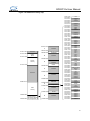
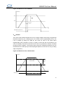
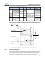
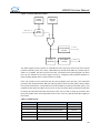
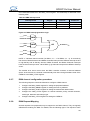
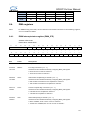
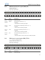
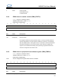
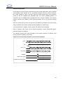
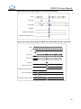
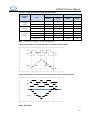
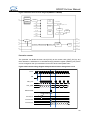
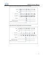
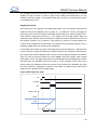
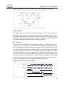
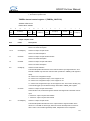
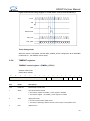
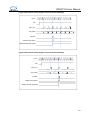
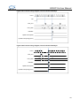
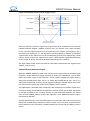
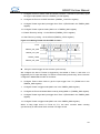
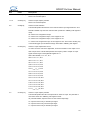
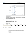
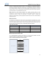
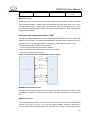
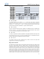
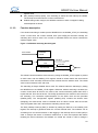
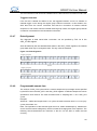
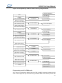
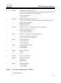
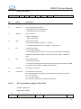
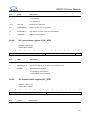
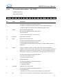
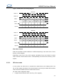
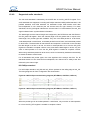
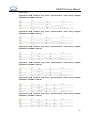
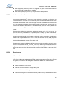
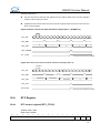
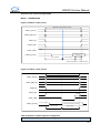
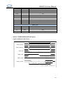
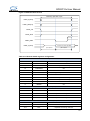
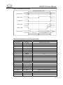
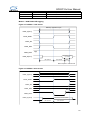
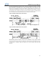
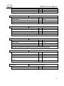
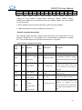
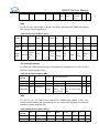
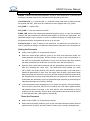
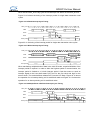
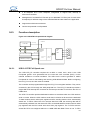
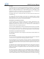
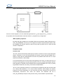
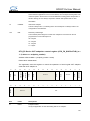
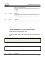
Figure 9-104 Output compare mode, toggle on OC1
CNT_REG
CHCC1
0039
003A
003B
003A
B200
B201
B201
Write B201h in the CHCC1
register
oc1ref=OC1
Match detected on CHCC1
Interrupt generated if enabled
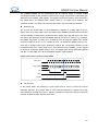
When the channel is used as a capture input, the counter value is captured into the Channel
Capture/Compare Register (TIMERx_CHCCx) when an effective input signal transition
occurs. Once the capture event occurs, the CHxIF flag in the TIMER1_STR register is set. If
the CHxIF bit is already set, i.e., the flag has not yet been cleared by software, and another
capture event on this channel occurs, the corresponding channel Over-Capture flag, named
CHxOF, will be set.Once the capture event occurs, a DMA request is generated depending
on the CHxDE bit and an interrupt is generated depending on the CHxIE bit
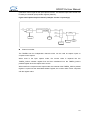
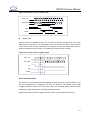
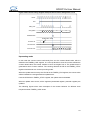
The input capture mode can be also used for pulse width measurement from signals on the
TIMERx_CHx pins (TIx).
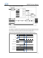
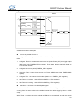
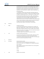
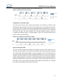
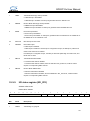
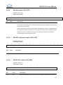
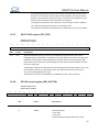
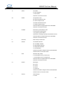
Channel Output Reference Signal
When the TIMER9/TIMER12 is used in the compare match output mode, the OCxREF signal
(Channel x Output Reference signal) is defined by setting the CHxOM bits. The OCxREF
signal has several types of output function. These include, keeping the original level by
setting the CHxOM field to 0x00, set to 1 by setting the CHxOM field to 0x01, set to 0 by
setting the CHxOM field to 0x02 or signal toggle by setting the CHxOM field to 0x03 when
the counter value matches the content of the TIMERx_CHCCx register.
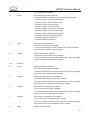
The PWM mode 1 and PWM mode 2 outputs are also another kind of OCxREF output which
is setup by setting the CHxOM field to 0x06/0x07. In these modes, the OCxREF signal level
is changed according to the counting direction and the relationship between the counter
value and the TIMERx_CHCCx content. With regard to a more detailed description refer to
the relative bit definition.
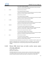
Another special function of the OCxREF signal is a forced output which can be achieved by
setting the CHxOM field to 0x04/0x05. Here the output can be forced to an inactive/active
level irrespective of the comparison condition between the counter and the TIMERx_CHCCx
values.
311