1
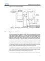
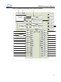
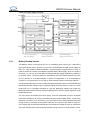
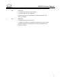
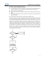
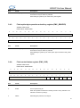
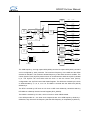
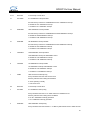
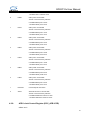
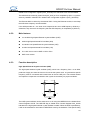
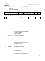
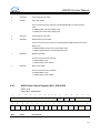
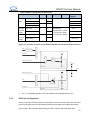
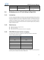
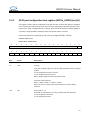
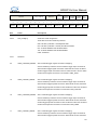
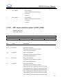
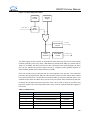
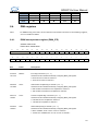
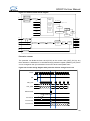
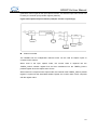
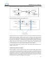
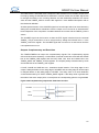
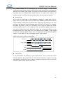
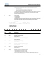
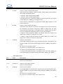
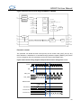
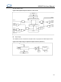
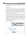
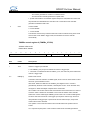
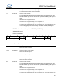
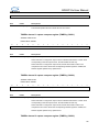
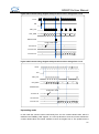
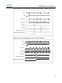
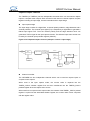
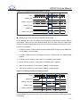
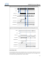
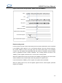
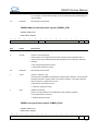
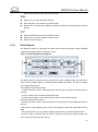
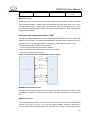
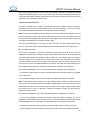
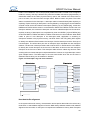
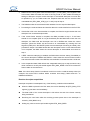
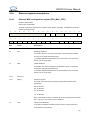
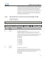
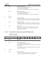
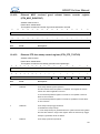
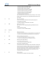
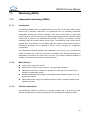
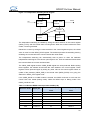
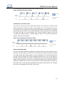
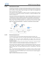
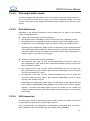
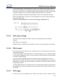
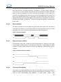
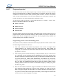
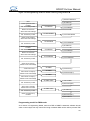
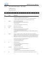
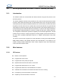
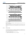
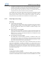
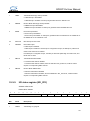
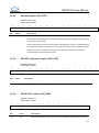
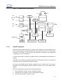
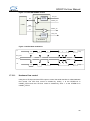
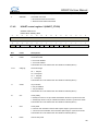
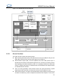
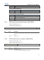
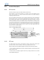
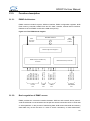
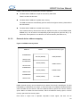
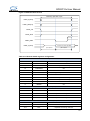
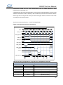
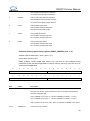
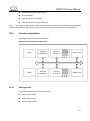
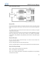
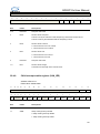
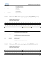
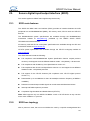
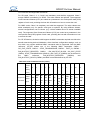
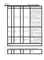
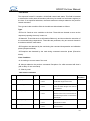
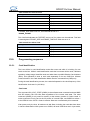
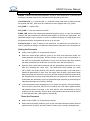
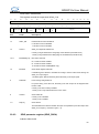
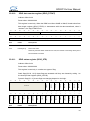
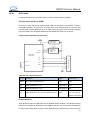
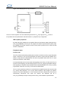
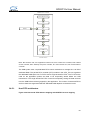
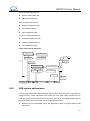
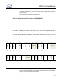
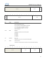
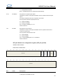
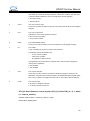
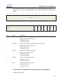
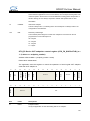
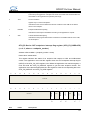
GD32F10x User Manual frames transmitted in Store-and-Forward mode. DMA Support ring or chain descriptor chaining. Each descriptor can transfer up to 8 KB of data. Round-robin or fixed-priority arbitration between reception and transmission controller priority. PTP Support IEEE1588 time synchronization function. Support two correction methods: Coarse or fine. Pulse per second output. Block Diagram The Ethernet module is composed of a MAC (media access controller) module, MII/RMII module and a DMA module by descriptor control. Figure 10-1 ETH module block diagram TxMAC MII Inter face AHB Arbiter RxMTL (2k tbuf) RxDMA AHB Slave IF Ethernet Reg MSC RMII Inter face RxMAC Time Stamp Gen (PTP IEEE 1588) Ethernet Phy AHB Master IF TxMTL (2k tbuf) TxDMA Mux 10.2.1. Station Management The MAC module is connected to the external PHY by MII or RMII through one selection bit (refer to AFIO_PCFR1 register). The SMI interface (MDIO and MDC), is used to configure and manage external PHY. Transmitting data module includes: - Tx DMA controller, used to read descriptors and data from memory and writes status to memory. - Tx FIFO, used to cache for MAC transmission data. - The MAC transmission control register group, used to control frame transmit. Receiving data module includes: - Rx DMA controller, used to read descriptors from memory and writes data and status to memory. - MAC receive control register group, used to control frame receive and marked the receiving state. - The receiving filter, can use a variety of filtering mode, filter out specific Ethernet frame - Rx FIFO, delay a received frame to achieve, thus filter can filter out specific frames, and then receives the frame into the memory. 357