1
GD32F10x User Manual
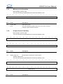
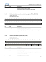
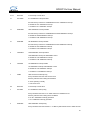
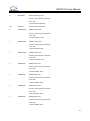
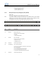
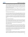
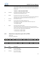
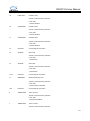
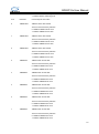
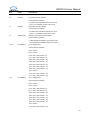
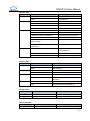
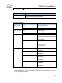
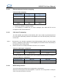
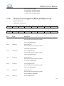
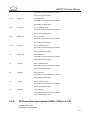
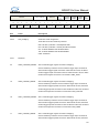
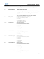
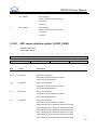
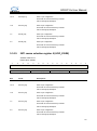
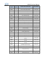
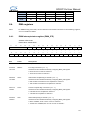
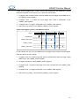
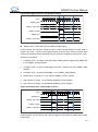
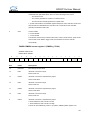
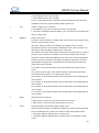
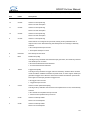
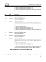
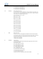
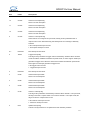
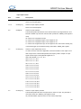
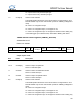
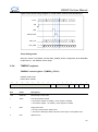
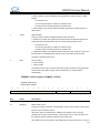
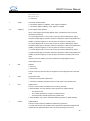
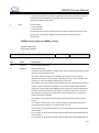
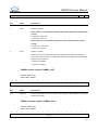
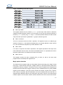
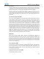
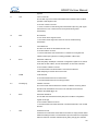
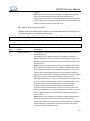
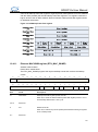
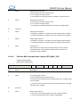
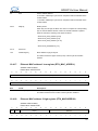
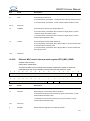
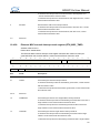
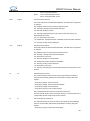
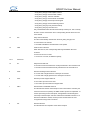
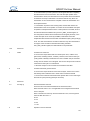
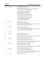
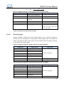
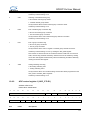
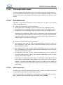
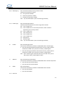
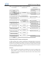
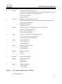
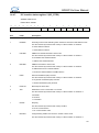
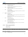
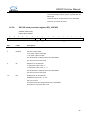
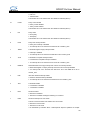
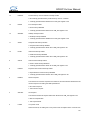
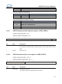
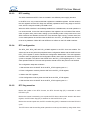
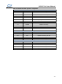
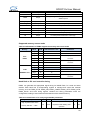
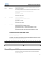
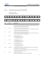
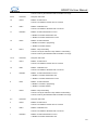
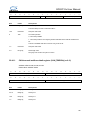
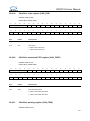
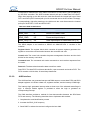
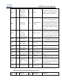
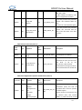
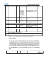
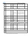
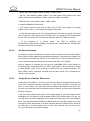
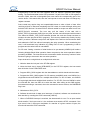
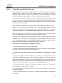
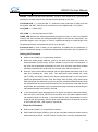
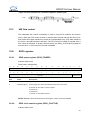
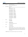
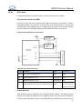
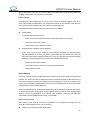
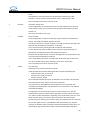
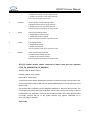
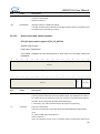
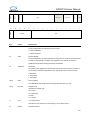
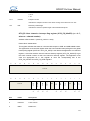
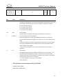
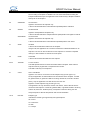
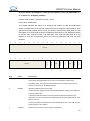
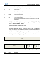
Applies to non-periodic IN endpoints only.
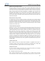
This interrupt is triggered on a endpoint for which an IN token was received when the
associated Tx FIFO (periodic/non-periodic) was empty.
3
TOC
Timeout condition
Applies only to control IN endpoints.
Indicates that the core has detected a timeout condition on the USB for the last IN
token on this endpoint.
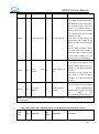
1
EPDISIF
Endpoint disabled interrupt flag
Indicates that the endpoint is disabled according to the application’s request.
0
XFIF
Transfer finished interrupt flag
Indicates that the programmed transfer is finished on the AHB as well as on the USB,
for this endpoint.
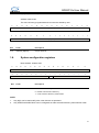
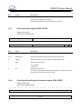
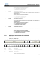
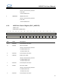
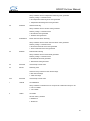
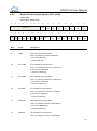
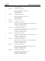
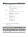
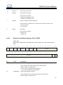
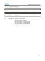
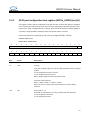
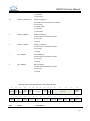
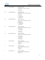
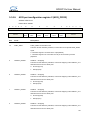
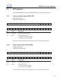
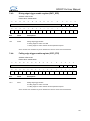
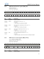
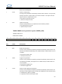
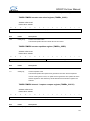
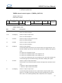
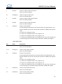
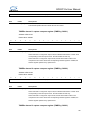
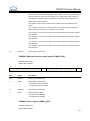
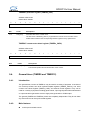
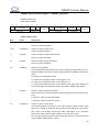
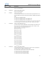
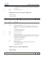
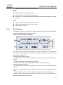
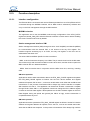
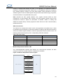
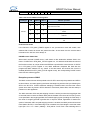
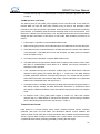
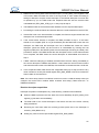
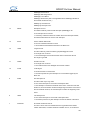
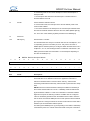
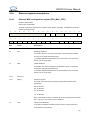
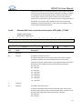
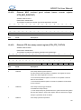
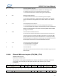
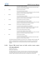
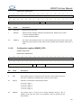
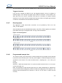
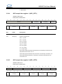
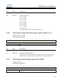
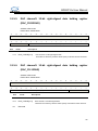
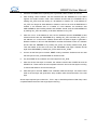
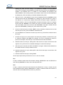
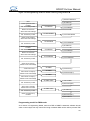
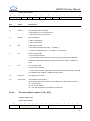
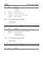
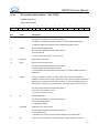
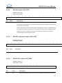
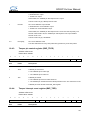
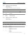
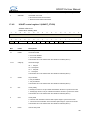
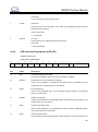
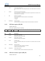
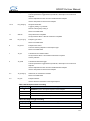
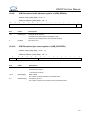
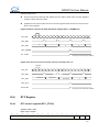
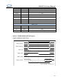
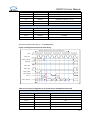
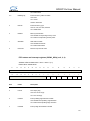
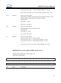
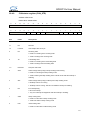
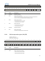
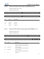
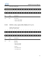
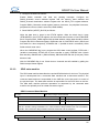
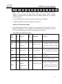
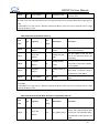
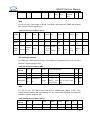
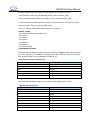
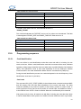
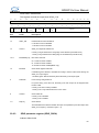
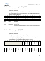
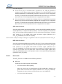
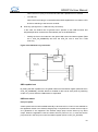
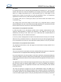
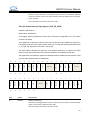
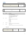
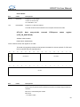
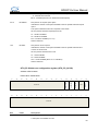
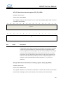
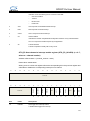
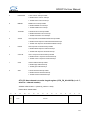
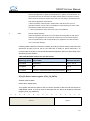
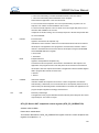
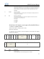
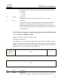
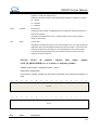
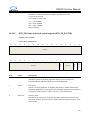
OTG_FS Device OUT endpoint-n interrupt flag register (OTG_FS_DOEPnIFR)
(n = 0..3, where n = endpoint_number)
Address offset: 0x0B08 + (endpoint_number × 0x20)
Reset value: 0x0000 0000
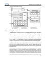
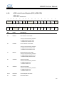
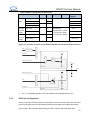
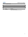
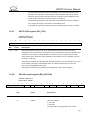
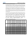
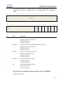
This register indicates the status of an endpoint with respect to USB- and AHB-related
events. The application must read this register when the OUT endpoints Interrupt flag bit
(OEPIF) of the OTG_FS_GIFR register is set. Before the application can read this register, it
must first read the OTG_FS_DAEPINT register to get the exact endpoint number. The
application must clear the appropriate bit in this register to clear the corresponding bits in the
OTG_FS_DAEPINT and OTG_FS_GIFR registers.
31
30
29
28
27
26
25
24
23
22
21
20
19
18
17
16
6
5
4
3
2
1
0
Reserved
15
14
13
12
11
10
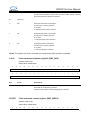
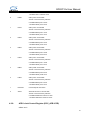
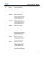
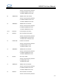
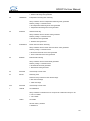
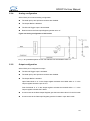
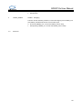
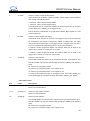
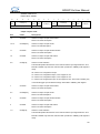
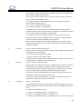
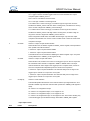
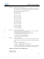
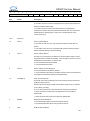
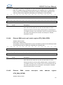
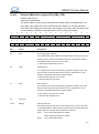
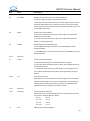
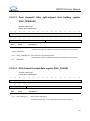
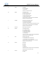
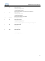
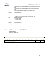
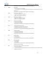
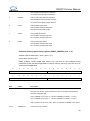
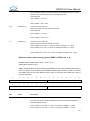
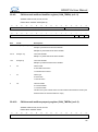
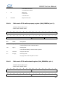
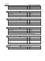
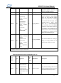
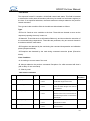
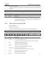
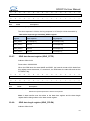
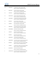
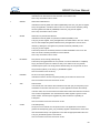
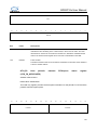
SETUP
EPDISIF
XFIF
Fields
7
OTREPD
Bits
8
BTBSETUP
Reserved
9
rc_w1
rc_
rc_
rc_
rc_w
/rw
w1
w1
w1
1
Res
Res
Descriptions
834