1
Connecting TCAD To Tapeout
A Journal for Circuit Simulation and SPICE Modeling Engineers
IBIS Models Now Supported in SmartSpice
1. Introduction
The Input/output Buffer Information Specification (IBIS) is a standard for electronic behavioral models based on I/V and V/T curve
data. It is being developed by the IBIS Open
Forum, which is affiliated with the Electronics
Industry Alliance (EIA). These models are
suitable for high-speed designs of digital systems
to evaluate Signal Integrity issues (deformation
of electronic signals, cross-talk, power/ground
bounce, transmission lines...) on printed circuit
boards (PCBs).
The IBIS standard offers a way to provide fast
and accurate models of I/O buffers without
divulgating any proprietary technology process.
As it protects IP, it is now widely used by
semiconductor vendors as a replacement for
SPICE netlists. The IBIS standard specifies
only what kind of information is provided,
how this information is presented in ASCII
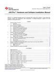
Figure1. IBIS Buffer General Circuit Diagram
Several elements and terminals are optional depending
on the buffer type: Input (node IN) and Enable (node
EN) high-impedance inputs, Output (node OUT) voltage
source and conductance, Pullup/Pulldown (nodes PU/
PD) Voltage-Controlled Voltage Sources (VCVS). Only
Input/Output buffers have all elements and all terminals
available. The number of terminals and the description
of the equivalent circuit are given in Table 1 for all buffers
currently supported in SmartSpice.
files and how some data are derived from measurements
or simulations. How these data are used and processed
by a simulator is not part of the standard. The purpose of
this documentation is to present the IBIS model support
in SmartSpice.
The reader who is not familiar with the IBIS standard or
would like to learn more about IBIS may refer to the Web
site of the IBIS Open Forum at “http://www.eigroup.org/ibis”
where numerous documents are available for download,
including introductions, slide shows, articles and complete
specifications (from the initial v1.0 to the latest v4.1 of
January 2004).
Continued on page 2 ...
INSIDE
2. IBIS Buffer Equivalent Circuit
A buffer is implemented as a new element in SmartSpice.
Even though different types of buffers are available to
cover a wide range of functions and technologies, they
are all base on the same equivalent circuit, which is
shown on Figure 1.
Volume 14, Number 4, April 2004
April 2004
Extraction of SPICE Model Parameters from
ATLAS Device Simulation Using UTMOST ........ 7
Calendar of Events...................................................... 9
Hints, Tips, and Solutions ......................................... 10
Page 1
The Simulation Standard
Type/Number
Terminals
(min/max)
Input
Enable
Output
Pullup
Pulldown
three_state/4
5/7
yes
yes
no
yes
yes
open_drain/5
4/6
yes
no
no
no
yes
io_open_drain/6
6/8
yes
yes
yes
no
yes
open_sink/7
4/6
yes
no
no
no
yes
io_open_sink/8
6/8
yes
yes
yes
no
yes
open_source/9
4/6
yes
no
no
yes
no
io_open_source/10
6/8
yes
yes
yes
yes
no
4
no
no
yes
no
no
output_ecl/12
3/5
yes
no
no
yes
yes
io_ecl/13
5/7
yes
yes
yes
yes
yes
series/15
NA
NA
NA
NA
NA
NA
series_switch/16
NA
NA
NA
NA
NA
NA
terminator/17
3/3
no
no
no
no
no
input_ecl/11
Table 1. Description of the equivalent circuit for all buffer types
The Gnd node corresponds to the SPICE ground node,
also called node 0. All connections to Gnd are internal
(C_comp, Vout...) and so this node is not available as
a terminal. The die capacitance C_comp specified in
IBIS models is usually connected between IO node
and ground. However, if die capacitances C_comp_pc,
C_comp_gc, C_comp_pu and C_comp_pd are specified
in the IBIS model instead of C_comp, these four capacitances are connected between IO and PC, GC, PU and
PD nodes, respectively.
this information without adding any external elements
in the netlist. The optional package circuitry is internally
created between IO terminal and DIE internal node
when the instance parameters component and/or pin
are specified on the device line. If component and pin are
not specified, DIE and IO nodes are connected together to
ensure compatibility with other simulators.
3. IBIS Buffer Device Line
Using buffers in SmartSpice is identical to using other
elements like passive or semiconductor devices. The general syntax of a buffer statement is given by:
PC/PU and GC/PD terminals are usually supposed
to connect to power and ground rails, respectively. By
default they are connected to internal voltage sources
(not shown on the circuit diagram) and should not be
connected to any other elements in the netlist (especially
voltage sources). However the instance parameter power
may be used to allow connections to external elements or
power supplies.
Bname term1 term2 term3 [term4 [term5 [term6
[term7 [term8]]]]]
+ file = ‘filename’
+ [model = ‘modelname’] [component=’componentname’
[pin=’pinname’]]
Series and Series_switch buffers are currently not supported
in SmartSpice. Terminator buffers also account for
extra parameters corresponding to passive elements.
These elements are not shown on the figure above. The
complete equivalent circuit for terminators is given below
with the information specific to terminators.
+ [typ = {typ|min|max|fast|slow}]
Optional Package Circuitry
+ [ramp_fwf] = {0|1|2}
Usually, buffers correspond to [Model] descriptions in
IBIS files, which do not include package parasitics. The
corresponding RLC elements may be added manually
in the netlist using the values specified via [Package]
or [Pin] keywords in IBIS files. However SmartSpice
offers a simple alternative to automatically account for
+ [fwf_tune = value] [rwf_tune = value]
The Simulation Standard
+ [power = {on|off}]
+ [interpol = {1|2}]
+ [buffer = {number|type}]
+ [ramp_rwf] = {0|1|2}
+ [c_comp_pc = value]
+ [c_comp_gc = value]
+ [c_comp_pu = value]
+ [c_comp_pd = value]
Page 2
April 2004
Device Naming Convention
•
The buffer element name must begin with B followed by
optional alphanumeric characters.
Optional Parameters
Terminals
component and pin are used to account for package
parasitics. If component is specified, SmartSpice first
checks whether a [Component] description named
‘componentname’ exists in the IBIS file, then gets the values
of R_pkg, L_pkg and C_pkg from the corresponding
[Package] description. R_pkg, L_pkg and C_pkg sub-parameters correspond to ranges in IBIS files, so the values
used for the simulation also depend on the value of typ.
If pin is also specified, SmartSpice checks whether a
pin named ’pinname’ exists in the [Pin] list associated
to the selected component. The first column of a [Pin]
list contains pin names. A [Pin] list is a sub-parameter
of a [Component] description in IBIS files. Consequently
pin should not be specified if component is missing on
the device line or if ’componentname’ does not match
a valid [Component] name. If the optional parameters
R_pin, L_pin and C_pin are available for the selected
pin, these values override the default package values
R_pkg, L_pkg and C_pkg, respectively. For this case,
R_pin, L_pin and C_pin do not correspond to ranges
and so are not dependent on the value of typ.
The number and the order of terminals specified on the
device line are type-dependent:
B_input PC GC IO OUT (Input and Input_ECL)
B_output PU PD IO IN [PC [GC]] (Ouput, Open_
drain, Open_sink, Open_source)
B_three_state PU PD IO IN EN [PC [GC]] (Three_state)
B_input_output PU PD IO IN EN OUT [PC [GC]]
(Input_output, IO_open_drain, IO_open_sink and
IO_open_source)
B_output_ecl PU IO IN [PC [GC]] (Output_ecl)
B_io_ecl PU IO IN EN OUT [PC [GC]] (IO_ecl)
B_three_state PU IO IN EN [PC [GC]] (Three_state_ecl)
B_terminator PC GC IO (Terminator)
Open_drain, IO_open_drain, Open_sink and IO_open_
sink buffers have no pullup circuitry but PU terminal
must be specified even though not connected to internal
elements. Open_source and IO_open_source buffers
have no pulldown circuitry but PD terminal must be
specified even though not connected to internal elements. Ouput_ecl, Three_state_ecl and IO_ecl buffers
have pullup and pulldown circuitry but no PD terminal
because this latter node is internally connected to PU node.
typ must be set to select what column of all IBIS data will
be used during the simulation: TYP (default), MIN, MAX,
SLOW or FAST. If FAST or SLOW are specified, the column
MIN or MAX is selected depending on the IBIS parameter
as defined in table 2. This is especially usefull for best case /
worst case analysis. If min or max values are not available in
the IBIS model for a given parameter, typ values are used.
Required Parameters
Specifying file parameter is required to define the location
of the IBIS file containing the IBIS model description for
this buffer. In SmartSpice this parameter is also used to
decide if a B statement corresponds to a MESFET device
or to an IBIS buffer. See Backward Compatibility paragraph
below for further details.
power is used to select how the buffer is powered via
PC, GC, PU and PD nodes (if these latter nodes exist for
the given buffer type).
In order to find the [Model] section in IBIS file it is also
necessary to properly set model parameter. However if
component and pin are given, model becomes optional.
According to IBIS specifications, a valid pin description
always contains the name of the associated model, which
is used in SmartSpice as the default value of model.
•
‘filename’ is case-sensitive and must correspond either
to the absolute path to the IBIS file or the relative
path. For this latter case, IBIS files are searched from
the directory where the simulator run, from the
directory of the netlist containing the corresponding
B-statement (which may be different from the current
working directory) and from the paths specified via
the option ‘d_ibis’. For convenience, the characters
’\’ and ’/’ are valid path delimiters in fi le and d_ibis
arguments, regardless of the operating system.
April 2004
‘modelname’, ‘componentname’ and ‘pinname’ are
case-sensitive and must match one of the [Model],
[Component] and [Pin] names defined in the IBIS file.
•
If power is set to ‘on’ (default), these nodes are internally
connected to voltage sources whose values are taken
from the IBIS parameters: [POWER Clamp Reference], [GND Clamp Reference], [Pullup Reference],
[Pulldown Reference] (or [Voltage Range] if preceding
parameters are missing). For this case, terminal
names specified on the element card may be usefull
to print out the voltage values if needed.
•
If power is set to ‘off’, internal voltage sources are not
created and PC, GC, PU and PD nodes must connect to
external voltage sources either directly or through passive devices like RLC networks or transmission lines.
interpol is the interpolation method selector.
Page 3
•
If interpol is set to 1 (default), I/V curves are interpolated using linear interpolation.
•
If interpol is set to 2, quadratic bi-spline interpolation
is used. This latter method is usually not recommended and useless anyway if IBIS data are accurate.
The Simulation Standard
IBIS Parameter/Data
Fast
Slow
C_comp
min
max
C_comp_pc
min
max
C_comp_gc
min
max
C_comp_pu
min
max
C_comp_pd
min
max
Voltage_range
max
min
Pullup_reference
max
min
Pulldown_reference
min
max
Power_clamp_reference
max
min
Gnd_clamp_reference
min
max
Pulldown
max
min
Pullup
max
min
Gnd_clamp
max
min
Power_clamp
max
min
Ramp
max
min
Rising_waveform
max
min
Falling_waveform
max
min
V_fixture
max
min
R_pkg
min
max
L_pkg
min
max
C_pkg
min
max
These latter option is highly recommended to get accurate results in transient analysis. However, if the required data are not available in IBIS model, the value of
ramp_fwf (or ramp_rwf) is decremented and a warning message is issued. For example, if ramp_fwf = 2 and
only one waveform table is given, then ramp_fwf is set
to 1, if ramp_fwf =1 and only ramp data are given, then
ramp_fwf is set to 0.
fwf_tune and rwf_tune factors are control parameters
for ramp_fwf =0, 1 and ramp_rwf = 0, 1 algorithms,
respectively. When only ramp data or one waveform is
available, it is necessary to impose an additional condition to compute multipliers. Usually it is assumed that
Ku(t)+K(t)=1, which was demonstrated to be not realistic
because the circuitry that goes from ON to OFF undergoes this transition faster than the circuitry that goes
from OFF to ON.
By setting fwf_tune or rwf_tune to a value between
0 and 1 (default 0.1), it is possible to get more accurate
transitions by using the following assumption: if deltaT
is the duration of a complete transition, the multiplier
K(t) corresponding to the circuitry that goes from ON
to OFF decreases linearly from 1 to 0 between t=0 and
t=fwf_tune * deltaT (or t=rwf_tune * deltaT depending
on the transition). Thus, the other multiplier is uniquely
determined from an IBIS ramp or one IBIS waveform.
The multiplier computation methods are described in
articles (1, 2).
C_comp_pc, C_comp_gc, C_comp_pu and C_comp_
pd are dimensionless die capacitance partionioning
factors. They do not override the IBIS parameters with
the same names, which correspond to actual die capacitances. If these latter capacitances are specified in the
IBIS model, the dimensionless factors are useless and
ignored if given on the element card. If only C_comp is
available in the IBIS model, it may be desirable to split it
into several parts for simulating power/ ground bounce.
This is achieved by specifying the fractions of C_comp
connected between IO node and PC, GC, PU, PD nodes.
If given, the values of instance parameters C_comp_pc,
C_comp_gc, C_comp_pu and C_comp_pd should be
between 0 (default) and 1. It is also expected that their
sum equals 1.
Table 2. Min/Max combinations for Slow/Fast conditions
buffer is used to specify the type of the buffer. This
value overrides the corresponding IBIS parameter
Model_type. It is usually not recommended to specify
a different value. Integer values are allowed to select a
buffer. The correspondence with literal names is given
in table 1.
ramp_fwf and ramp_rwf selectors allow the user to
choose the calculation method of multipliers Ku(t) and
Kd(t). These parameters are totally independent and may
have different values.
•
If ramp_fwf (or ramp_rwf) is set to 0 (default), only
the ramp data is used to derive multipliers for the
falling (or rising) transition
•
If ramp_fwf (or ramp_rwf) is set to 1, the first falling (or rising) waveform table available in IBIS model
is used to derive corresponding multipliers
•
If ramp_fwf (or ramp_rwf) is set to 2, the first two
falling (or rising) waveform tables available in IBIS
model are used to derive corresponding multipliers
The Simulation Standard
4. Buffer Logical State
The logical state of a buffer is controlled by the voltage
of IO, IN and/or EN nodes relative to ground and noted
Vio, Vin and Ven, respectively.
For buffers with no controlling signals (no IN or EN
nodes), the state is a function of Vio, the IBIS parameters
Vin_l, Vin_h (thresholds), Polarity and the previous state
if any.
Page 4
April 2004
If Polarity=Non-Inverting
• Initially (t=0 in transient analysis or first computed
point of a DC sweep), buffer is ENABLE if Ven<0.5 or
DISABLE in the opposite case.
• Initially (t=0 in transient analysis or first computed
point of a DC sweep), state is set to LOW if Vio<(Vin_
h+Vin_l)/2 or to HIGH in the opposite case.
• If buffer=ENABLE then it goes to DISABLE only if
Ven>0.8.
• If state=HIGH then it goes to LOW only if Vio<Vin_l.
• If buffer=DISABLE then it goes to ENABLE only if
Ven<0.2.
• If state=LOW then it goes to HIGH only if Vio>Vin_h.
else Polarity=Inverting
If a buffer is ENABLE, the state is controlled by Vin according to the rules defined above for buffers with only
one controlling signal (IN node).
• Initially (t=0 in transient analysis or first computed
point of a DC sweep), state is set to LOW if Vio>(Vin_
h+Vin_l)/2 or to HIGH in the opposite case.
If a buffer is DISABLE, there are two possible behaviors
depending on the type:
• If state=HIGH then it goes to LOW only if Vio>Vin_h.
• For buffers without output circuitry (no OUT node),
the state is just locked till the buffer returns to ENABLE. Three-state buffers belong to this family.
• If state=LOW then it goes to HIGH only if Vio<Vin_l.
For buffers with only one controlling signal (IN node),
the state is a function of Vin, the IBIS parameter: Polarity
and the previous state if any. Here thresholds are constant built-in parameters.
• For buffers with output circuitry (OUT node), the state
is controlled by Vio according to the rules defined
above for the buffers with no controlling signals. Input-output buffers belong to this family.
If Polarity=Non-Inverting
The logical state can be printed out if the output circuitry
(OUT node) is available:
• Initially (t=0 in transient analysis or first computed
point of a DC sweep), state is set to HIGH if Vin>0.5 or
to LOW in the opposite case.
• If state=HIGH then Vout=1.0V. If state=LOW then
Vout=0.0V.
• If state=HIGH then it goes to LOW only if Vin<0.2.
• OUT node can also connect to external elements, especially IN or EN nodes of other buffers. This nodes offer
a simple way to create complex digital blocks in SPICE
netlists.
• If state=LOW then it goes to HIGH only if Vin>0.8.
else Polarity=Inverting
• Initially (t=0 in transient analysis or first computed
point of a DC sweep), state is set to HIGH if Vin<0.5 or
to LOW in the opposite case.
5. Output Variables
The variables listed in table 3 can be printed out using
the SmartSpice syntax @B_name[variable_name]:
• If state=HIGH then it goes to LOW only if Vin>0.8.
• If state=LOW then it goes to HIGH only if Vin<0.2.
For buffers with two controlling signals (IN and EN
nodes), the state is a function of Ven, Vin, Vio, the IBIS
parameters: Vin_l, Vin_h (thresholds), Polarity, Enable
and the previous state if any. The enable signal Ven supersedes the input signal Vin and is used to determine
whether the buffer is in ENABLE or DISABLE state:
Variable Name
Definition
ku
Pullup transient current multiplier
kd
Pulldown transient current multiplier
cio
Input/Output terminal current
If Enable=Active-High
cpc
Power Clamp terminal current
• Initially (t=0 in transient analysis or first computed
point of a DC sweep), buffer is ENABLE if Ven>0.5 or
DISABLE in the opposite case.
cgc
Ground Clamp terminal current
cpu
PullUp terminal current
cpd
PullDown terminal current
• If buffer=ENABLE then it goes to DISABLE only if
Ven<0.2.
cin
Input terminal current
cen
Enable terminal current
• If buffer=DISABLE then it goes to ENABLE only if
Ven>0.8.
cout
Output terminal current
Table 3. Buffer internal variables.
else Enable=Active-Low
April 2004
Page 5
The Simulation Standard
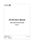
6. Terminator Buffers
A terminator is similar to an input buffer except that it
has no internal logical state (no output terminal, Vinh
and Vinl not required) and may include optional passive
elements as shown on Figure 2.
Rpower, Rgnd, Rac and Cac sub-parameters correspond
to ranges in IBIS files, so the values used for the simulation also depend on the value of typ. For ‘fast’ and ‘slow’
values, the column is choosen according to table 4. If
a value is not available or is unrealistic (negative resistance or capacitance), the corresponding element is
simply removed from the circuit. Cac must be set to a
positive value otherwise the entire branch Rac/Cac is not
created, even though Rac is set to a positive value.
IBIS Parameter/Data
Fast
Slow
Rpower
max
min
Rgnd
max
min
Rac
max
min
Cac
min
max
Figure2. Terminator Buffer Circuit Diagram.
8. Backward Compatibility
In previous releases of SmartSpice, B statements were
only used to define instances of MESFET models (as
an alias of Z). From now on, they may also be used to
define IBIS buffers. When a B statement is encountered
in a netlist, SmartSpice first checks whether the IBISspecific parameters fi le is specified in the element card.
As this parameter is required to create an IBIS buffer,
SmartSpice creates a MESFET device if they are missing,
so that backward compatibility is maintained.
9. Limitations
Table 4. Min/Max combinations for Slow/Fast conditions
(terminator elements).
•
Only DC, Transient and AC analysis are supported
for IBIS buffers.
Like other buffer types, the optional package circuitry is
internally created between IO terminal and DIE internal
node when the instance parameters component and/or
pin are specified.
•
Unlike other simulators, the IBIS Golden Parser is not
incorporated into SmartSpice yet. As a consequence
SmartSpice does not check the syntax of .ibs files and
just issues a generic ‘parse error’ message if the syntax of an .ibs file is not in compliance with IBIS v3.2
specifications. To avoid such problems all .ibs files
should be systematically verified with the Golden
Parser, freely available as an executable on the IBIS
Open Forum web site. If the Golden Parser reports
warnings and errors, the .ibs file can probably not be
used in SmartSpice netlists.
•
The series and series switch buffers are still not supported.
•
The capability for SmartSpice to use [Component]
descriptions is under development.
7. IBIS-Related Options
GMIN/DCGMIN conductances are connected in parallel
with PC and GC diodes and with PU and PD VoltageControlled Voltage Sources if they exist (type-dependent) to ensure better convergence of buffer devices in
particular situations.
The option VZERO=2 can also be specified in netlists
containing IBIS buffers. This may help to speed-up computation in some cases.
A new option d_ibis has been added to specify the location of .ibs files. Several paths can be specified. A .ibs
file will be searched in all specified paths if the filename
given on B statements is not an absolute path and is not
found in the directory from which SmartSpice runs. This
option is case-sensitive. For example:
10. References
.option d_ibis=’/home/mylogin/myIbisModels’
d_ibis is also available as a variable and can be set in
SmartSpice .ini files. For example:
1]
Peivand F. Tchrani, Yuzhe Chen, Jiayuan Fang, “Extraction of transient behavioral model of digital I/O buffers from IBIS”, 46th IEEE
Electronic Components&Technology Conference, Orlando, May
28-31, 1996, pp 1009-1015
2]
Ying Wang, Han Ngee Tan, “The development of analog SPICE
behavioral model based on IBIS model”, Ninth Great Lakes Symposium on VLSI, pp.101-104, 1999
set d_ibis = ( . /home/mylogin/myibismodels )
The Simulation Standard
Page 6
April 2004
Extraction of SPICE Model Parameters from ATLAS
Device Simulation Using UTMOST
Many users would like to extract SPICE models from
their process and device simulation using ATHENA and
ATLAS to be used in actual circuit simulation without
actually fabricating the device.
Using SILVACO’s UTMOST you can extract SPICE
model parameters from the simulation results of
ATHENA and ATLAS.
To guide users on how to go about extracting SPICE
model parameters an example which extracts BSIM3v3
model from process/device simulation is used in this
article.
All these commands can be executed from a single software – DeckBuild.
The commands are heavily commented so that you
know their functions and purpose.
Here we will concentrate on the UTMOST batch mode
commands. Here we only cover a very simple case and
there is no local optimization. The UTMOST interactive
mode can be used save the UTMOST setup into a file .
UTMOST interactive cannot be executed from DeckBuild.
Figure 1. TonyPlot of Decice structure.
-----------
start of deckbuild commands -------------
# Commands that can be used in deckbuild to extract
# Spice model Parameters. The deck for TCAD is
# not complete . Below are examples of commands that
# maybe used in VWF Athena and Atlas to obtain the
# device characteristics
###### START ATHENA SIMULATION ###
# Run process simulation
go athena
# Extract the poly length LD
extract name=”ld” thick poly y.val=0
extract name=”utmost_ld”($ld*1.0e-4)
....
extract thickness oxide mat.occno=1 name=”tox”
extract name=”utmost_tox” ($tox*1.0e-10)
....
###### START ATLAS DEVICE SIMULATION ##
go atlas
Figure 2. DeckBuild screen.
April 2004
Page 7
The Simulation Standard
###### Create the IdVg-Vb IV matrix ###
# define parameters to be set when the data is
# read from ssf file from ATLAS
load infi le=solve1.log
log outf=mos2ex06_IdVg-Vb.log
setup NRS=0.04 NRD=0.04 width=1.0 \
solve name=gate vgate=0 vfinal=5 vstep=0.2
length=$utmost_ld polarity=N
load infi le=solve2.log
# load Atlas log files simulated earlier.
solve name=gate vgate=0 vfinal=5 vstep=0.2
# the master option tells UTMOST the file is in
load infi le=solve3.log
# VWF ssf format
solve name=gate vgate=0 vfinal=5 vstep=0.2
....
init inf=mos2ex06_IdVg-Vb.log master
# Simulate device ID/VG characteristics
# Load in append mode, more results from the logfile
solve vgate=1 vstep=0.25 vfinal=1.5 name=gate \
outf=solve_tmp0 onefi le
init inf=mos2ex06_IdVd-Vg.log master append
solve vgate=1.75 vstep=0.25 vfinal=3 name=gate \
outf=solve_tmp1 onefi le
# select required characteristics for device 1
solve vgate=3.25 vstep=0.25 vfinal=4.5 name=gate \
outf=solve_tmp2 onefi le
# (there is only 1 device)
# unselect all ID/VG-VB first the select device 1
....
deselect ID/VG-VB all
##### Create the IdVd-Vg IV matrix #######
select ID/VG-VB device 1
log outf=mos2ex06_IdVd-Vg.log
# unselect all ID/VD-VG first, then select device 1
....
solve name=drain vdrain=0 vfinal=5 vstep=0.2
deselect ID/VD-VG all
solve name=drain vdrain=0 vfinal=5 vstep=0.2
select ID/VD-VG device 1
solve name=drain vdrain=0 vfinal=5 vstep=0.2
# Defines the routine for which data is to be stored
....
# in ssf format (standard structure format)
#### START UTMOST SIMULATION ####
output ID/VD-VG
#*************************************
# Stores measured data (simulated by ATLAS) to
# Jump to UTMOST MOS module
# ssf log File in uniform steps as required by UTMOST
go utmost
utmost type = mos
log outf=mos2ex06_data.log measured
# The model command loads Utmost setup file
# setup the UTMOST log file to store
# created by interactive session .
# The measured (simulated data from ATLAS).
model MOS_vwf_bsim3_n
log outf=mos2ex06_ut.log utmost
# change the Value for gate oxide thickness for
# set up output log file for simulated data created
#by UTMOST routine which was last referred to
#Opt(imization) and Fit Columns .
#by batch mode output command i.e ID/VD-VG
device TOX = $utmost_tox
The Simulation Standard
log outf=mos2ex06_sim.log simulated
Page 8
April 2004
# Perform curve fitting for selected routines
+UB= 5.87E-19
UC= -4.65E-11
VSAT= 8E4
# and then do local optimization sequences
+A0 = 1
AGS = 0
B0= 0
# if they are defined in setup file.
+B1 = 0
KETA = -0.047
A1 = 0
+A2 = 1
RDSW = 0
PRWG = 0
+PRWB = 0
WR
PRWG = 0
+LINT = 0
DWG
+VOFF = -0.1
NFACTOR = 1
CIT
+CDSC = 2.4E-4
CDSCD = 0
CDSCB = 0
+ETA0 = 0.08
ETAB
DSUB
+PCLM = 1.3
PDIBLC1 = 0.39
PDIBLC2 = 8.6E-3
+PDIBLCB= 0
DROUT = 0.56
PSCBE1 = 4.24E8
+PSCBE2 = 5E-5
PVAG
DELTA = 0.01
+MOBMOD = 1
PRT
# to an existing file.
+KT1
KT1L
+UA1 = 4.31E-9
UB1 = -7.61E-18
UC1 = -5.6E-11
save outf=mos2ex06.ssf
+AT
NQSMOD = 0
WL
WW
WWN
fit ID/VG-VB
fit ID/VD-VG
# perform simulation for selected routines
simulate ID/VD-VG
# Output Utmost parameters for extraction.
# Save results to file in a ssf file. If
# append option is used the parameters are appended
+WLN
##### Extract UTMOST parameters ########
# load output parameter file from UTMOST
=0
= 3.3E4
=1
=1
= -0.07
=0
+LW
LWN
=0
=0
= 0.56
UTE = -1.5
=0
KT2 = 0
=0
LL
=0
DWB
=0
+WWL = 0
+CAPMOD = 1
=0
=0
=1
=0
=1
LLN
=1
LWL
=0
)
*
extract init infi le=”mos2ex06.ssf”
# Save the current parameter set from the
References
# Optimization column of UTMOST parameter
1]
UTMOST III User’s Manual – Chap 14. Batch Mode Operation
# to a model library file
2]
UTMOST III Extractions Manual , Vol. 1- Appendix A – BSIM3v3
Extraction Tutorial
3]
Silvaco example file examples/mos2/mos2ex6.in
4]
TCAD Tutorial and Examples Vol.1 p.2-26
create library=mos2ex06.lib
# EXIT
quit
------------ end of Deckbuild commands ----------A portion of mos2ex06.lib file is as follows.
.LIB CMOS
*
.MODEL MMOD NMOS ( LEVEL = 8
+TNOM = 27
TOX = 1E-8
XJ = 1.5E-7
+NCH=1.7E17
NSUB=6E16
VTH0 =0.5776647
+K1= 0.5
K2 = -0.0186
K3 = 80
+K3B= 0
W0= 2.5E-6
NLX = 1.74E-7
+DVT0W= 0
DVT1W= 0
DVT2W =-0.032
+DVT0 = 2.2
DVT1
DVT2
+VBM= -5
U0 = 670
April 2004
= 0.53
= -0.032
UA= 2.25E-9
Page 9
The Simulation Standard
Calendar of Events
April
1
2
3
4
5
6
7
8
9
10
11
12
13
14
15
16
17
18
19
20
21
22
23
24
25
26
27
28
29
30
May
1
2
3 GaAs MANTECH - Miami
Beach, FL
4 GaAs MANTECH - Miami
Beach, FL
5 GaAs MANTECH - Miami
Beach, FL
6 GaAs MANTECH - Miami
Beach, FL
7
8
9
10
11
12
13
14
15
16
17
18 CLEO - San Francisco, CA
19 CLEO - San Francisco, CA
20 CLEO - San Francisco, CA
21
22
23
24
25
26
27
28
29
30
31
Bulletin Board
Silvaco Rolls Out High
Voltage IC Design Tool Suite
Silvaco released its integrated High Voltage
IC Design Tool Suite to address the unique
needs of designers of high voltage ICs such
as LCD drivers, TFT drivers, automotive,
industrial, motor control, and power
management ICs for laptops, PDAs, and
other battery operated electronics. “Gateway integrates design capture with our
circuit simulation environment, and schematic driven layout,” said Ken Brock, vice
president of marketing at Silvaco. “Our
productive layout/verification tools supported with PDKs, complete the world’s
best integrated tool flow for high voltage
IC design.”
Silvaco at GaAs MANTECH
Silvaco’s TCAD team was out in force
at GaAs MANTECH, the premier conference for compound semiconductor
process and device physics. Featured
were the latest advances in optical TCAD
software featuring Blaze 2D & 3D Device
Simulator for Advanced Materials, LASER Semiconductor Laser Diode Simulation, VCSEL Vertical Cavity Surface
Emitting Laser Simulation, Luminous
Optoelectronic Device Simulator, Giga
Non-Isothermal
Device
Simulation,
Quantum Simulation Models for Quantum Confinement Effects, and the Noise
2D Small Signal Noise Simulator.
If you would like more information or to register for one of our our workshops, please check our web site at http://www.silvaco.com
The Simulation Standard, circulation 18,000 Vol. 14, No. 4, April 2004 is copyrighted by Silvaco International. If you, or someone you know wants a subscription to
this free publication, please call (408) 567-1000 (USA), (44) (1483) 401-800 (UK), (81)(45) 820-3000 (Japan), or your nearest Silvaco distributor.
Simulation Standard, TCAD Driven CAD, Virtual Wafer Fab, Analog Alliance, Legacy, ATHENA, ATLAS, MERCURY, VICTORY, VYPER, ANALOG EXPRESS,
RESILIENCE, DISCOVERY, CELEBRITY, Manufacturing Tools, Automation Tools, Interactive Tools, TonyPlot, TonyPlot3D, DeckBuild, DevEdit, DevEdit3D,
Interpreter, ATHENA Interpreter, ATLAS Interpreter, Circuit Optimizer, MaskViews, PSTATS, SSuprem3, SSuprem4, Elite, Optolith, Flash, Silicides, MC Depo/
Etch, MC Implant, S-Pisces, Blaze/Blaze3D, Device3D, TFT2D/3D, Ferro, SiGe, SiC, Laser, VCSELS, Quantum2D/3D, Luminous2D/3D, Giga2D/3D,
MixedMode2D/3D, FastBlaze, FastLargeSignal, FastMixedMode, FastGiga, FastNoise, Mocasim, Spirit, Beacon, Frontier, Clarity, Zenith, Vision, Radiant,
TwinSim, , UTMOST, UTMOST II, UTMOST III, UTMOST IV, PROMOST, SPAYN, UTMOST IV Measure, UTMOST IV Fit, UTMOST IV Spice Modeling,
SmartStats, SDDL, SmartSpice, FastSpice, Twister, Blast, MixSim, SmartLib, TestChip, Promost-Rel, RelStats, RelLib, Harm, Ranger, Ranger3D Nomad, QUEST,
EXACT, CLEVER, STELLAR, HIPEX-net, HIPEX-r, HIPEX-c, HIPEX-rc, HIPEX-crc, EM, Power, IR, SI, Timing, SN, Clock, Scholar, Expert, Savage, Scout, Dragon,
Maverick, Guardian, Envoy, LISA, ExpertViews and SFLM are trademarks of Silvaco International.
The Simulation Standard
Page 10
April 2004
Hints, Tips and Solutions
Atsushi Hasegawa
Hasegawa, Applications and Support Engineer
Array Copying - Alignment from Specified
Instance Number
3. Delete X99.
After array coping is completed, you delete “X99”
that is not necessary.
For LCD and Memory designs, Array Copy function on
Gateway is conveniently used. Users may want to align
instances from specified instance number, for example
starting from X100 or X1000. Here introduces a convenience way to realize it.
4. Array copying for nets.
As well as instances, Gateway presents the array
copying for nets.
First off you put an initial net, “NET1” like the Figure.4, and then you select it and copy and array paste
in 4x3, Figure.5.
1. Place an initial instance.
First, user puts an instance and renames it “X99”.
Figure 1.
2. Copy and Array paste with some settings.
Then you select “X99” and copy and array paste like
the Figure.2, Gateway generates an aligned array
from “X100”, Figure.3.
Figure 4
Figure 5.
Conclusion
Figure 2.
Gateway automatically generates an instance name next
to the latest one, if the latest is X1, next one is X2. In addition, user can copy a net in an array as well as instances
with X,Y copy number and pitch. When you finish creating the schematic or in LVS checking, you can easily
predict and find out a target instance is where.
Call for Questions
If you have hints, tips, solutions or questions to contribute,
please contact our Applications and Support Department
Phone: (408) 567-1000
Fax: (408) 496-6080
e-mail: [email protected]
Hints, Tips and Solutions Archive
Check our our Web Page to see more details of this example
plus an archive of previous Hints, Tips, and Solutions
www.silvaco.com
Figure 3.
April 2004
Page 11
The Simulation Standard
20 Years and Growing
Financially Rock-Solid
Fiercely Independent
Analog/MS EDA Design Leader
Contacts:
Silvaco Japan
[email protected]
Silvaco Korea
[email protected]
USA Headquarters:
Silvaco Taiwan
[email protected]
Silvaco International
4701 Patrick Henry Drive, Bldg. 2
Santa Clara, CA 95054 USA
Silvaco Singapore
[email protected]
Silvaco UK
[email protected]
Phone: 408-567-1000
Fax: 408-496-6080
Silvaco France
[email protected]
[email protected]
www.silvaco.com
Silvaco Germany
[email protected]
Products Licensed through Silvaco or e*ECAD
The Simulation Standard
Page 12
April 2004