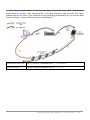
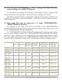
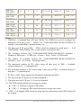
1
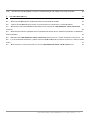
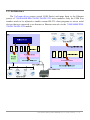
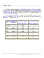
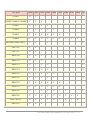
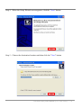
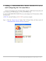
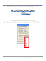
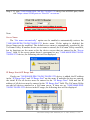
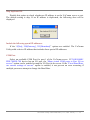
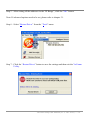
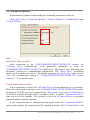
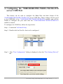
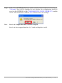
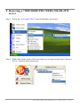
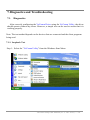
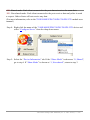
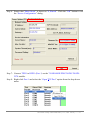
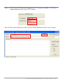
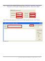
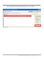
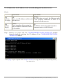
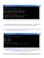
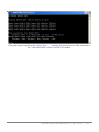
VxComm Utility User Manual 1. OVERVIEW 3 1.1. DRIVERS AND PLATFORMS 3 1.2. ARCHITECTURE 4 1.3. TCP PORTS 5 2. INSTALLING THE VXCOMM DRIVER 7 2.1. INSTALLATION OUTLINE 7 2.2. VXCOMM DRIVER INSTALLATION 7 3. ADDING A 7188E/8000E/PDS-700/DS-700/ZB-2570 SERVER & CONFIGURING THE VXCOMM DRIVER 3.1. ADVANCED OPTIONS 10 15 4. CONFIGURING THE 7188E/8000E/PDS-700/DS-700/ZB-2570 SERVER COM PORT 17 5. REMOVING A 7188E/8000E/PDS-700/DS-700/ZB-2570 SERVER 20 6. UNINSTALLING THE VXCOMM DRIVER 22 7. DIAGNOSTICS AND TROUBLESHOOTING 24 7.1. DIAGNOSTICS 24 7.1.1. LOOPBACK TEST 24 7.1.2. EXTERNAL DEVICES TEST 32 7.2. TROUBLESHOOTING 35 7.2.1. THE CLIENT PROGRAM FAILS TO OPEN THE COM PORT THAT WAS CREATED USING THE VXCOMM DRIVER. 35 7.2.2. THE CLIENT PROGRAM STILL FAILS TO OPEN THE COM PORT. 35 7.2.3. THE CLIENT PROGRAM SUCCESSFULLY OPENS THE COM PORT, BUT FAILS TO ACCESS THE DEVICE. 36 7.2.4. ENSURE THAT THE IP ADDRESS IS NOT CURRENTLY BEING USED BY OTHER DEVICES 37 VxComm Utility User Manual (V1.3, Jan. 2010) ----- 1 7.2.5. 8. ENSURE THAT THE IP ADDRESS, GATEWAY AND SUBNET MASK ARE CORRECT FOR YOUR NETWORK. VXCOMM DRIVER FAQ 8.1. 41 DOES VXCOMM DRIVER (PC) V2.00 WORK WITH VXCOMM SERVER V2.6.00? 8.2. DOES VXCOMM DRIVER (PC) SUPPORT AUTO-RECONNECTION AFTER FIXING A NETWORK BREAK? 8.3. 40 41 41 WHY DOESN'T THE VXCOMM DRIVER (PC) RECEIVE DATA FROM THE 7188E/8000E/PDS-700/DS-700/ZB-2570 MODULE? 8.4. 42 DOES THE TRANSMISSION SPEED BECOME FASTER WHEN THE SERIAL DEVICE WORKING WITH SERIAL TO ETHERNET DEVICE SERVERS? 43 8.5. WHY DOES THE 7188E/8000E/PDS-700/DS-700/ZB-2570 MODULE FAIL ON A (PUBLIC) INTERNET CONNECTION? 45 8.6. CAN I USE THE SETCOMMSTATE ( ) API TO CHANGES THE BAUD RATE/DATA FORMAT SETTINGS OF A VIRTUAL COM PORT? 8.7. 47 HOW MANY PCS CAN BE CONNECTED TO A SINGLE 7188E/8000E/PDS-700/DS-700/ZB-2570 DEVICE? VxComm Utility User Manual (V1.3, Jan. 2010) ----- 2 47 1. Overview “VxComm” stands for “Virtual Communications Ports.” The “VxComm Driver” package includes the driver, the utility and the online help files. 1.1. Drivers and Platforms Note: Use the driver appropriate to your Windows platform. Use VxComm98.exe for Windows 95/OSR2, 98/SE, ME Platform Windows 95 Windows 95 OSR2 Windows 98 Windows 98 SE Windows ME Version v4.00.950 v4.00.950 B v4.10.1998 v4.10.2222 A v4.90.3000 Use VxComm2K.exe for Windows NT 4.0, 2000/XP/2003 and Vista32 (32-bit) The driver (including the utility) is contained on the enclosed CD: CD: \Napdos\7188e\Tcp\VxComm\Driver (PC). The latest version can also be obtained from our web site: ftp://ftp.icpdas.com/pub/cd/8000cd/napdos/7188e/tcp/vxcomm/driver(pc)/ VxComm Utility User Manual (V1.3, Jan. 2010) ----- 3 1.2. Architecture The VxComm driver creates virtual COM Port(s) and maps them to the Ethernet port(s) of 7188E/8000E/PDS-700/DS-700/ZB-2570 series modules. Only the COM Port number needs to be adjusted to enable custom RS-232 client programs to access serial devices that are connected to an Internet or Ethernet network via the 7188E/8000E/PDS700/DS-700/ZB-2570 module. COM_? COM_? COM_? COM_? COM_2 COM_1 Port_? Port_3 Port_2 Port_1 VxComm Utility User Manual (V1.3, Jan. 2010) ----- 4 1.3. TCP Ports The default TCP Port numbers for 7188E/8000E/PDS-700/DS-700/ZB-2570 modules are 10000~10008, and can be used to access Ethernet/Internet Ports 1~8 of 7188E/8000E/ PDS-700/DS-700/ZB-2570 modules. Another TCP port number (9999) is dedicated to the virtual I/O only. Client programs can use this port (9999) to access the embedded I/O expansion board with A/D and D/A The VxComm driver uses Ports 1~8 to map to TCP ports 10001~10008, and uses the "Port I/O" to map to TCP port 9999. Users can then choose any virtual COM port(s) to map to Ports 1~8 and/or the Port I/O. COM Port VxComm Driver (PC) /Utility (PC) Not Used COM ? COM ? COM ? COM ? COM ? COM ? COM ? COM ? COM ? Reserved (Command) Port 1 Port 2 Port 3 Port 4 Port 5 Port 6 Port 7 Port 8 Port I/O VxComm Server (7188E/8000E/PDS700/DS-700/ZB-2570) 10000 10001 10002 10003 10004 10005 10006 10007 10008 9999 Ethnernet/Internet Port (7188E/8000E/PDS700/DS-700/ZB-2570) Reserved (Command) COM 1 COM 2 COM 3 COM 4 COM 5 COM 6 COM 7 COM 8 I/O VxComm Utility User Manual (V1.3, Jan. 2010) ----- 5 TCP port 10000 10001 10002 10003 10004 10005 10006 10007 10008 9999 7188E1 V V 7188E2/7188EA/7188EX V V V 7188E3 V V V V 7188E4 V V V V V 7188E5 V V V V V V 7188E8 V V V V V V 8430/8830/8431/8831 V V DS-712 V V DS-715 V V PDS-720 V V V PDS-721 V V V PDS-732 V V V V V PDS-734 V V V V V PDS-742 V V V V V PDS-743 V V V V V PDS-752 V V V V V V PDS-755 V V V V V V PDS-762 V V V V V V V PDS-782 V V V V V V V V V PDS-782-25 V V V V V V V V V ZB-2570 V V V V V V V V V V V VxComm Utility User Manual (V1.3, Jan. 2010) ----- 6 2. Installing the VxComm Driver 2.1. Installation Outline Windows NT/2000/XP/2003 and Vista32 (32-bit) 1. Install VxComm Driver 2K. (VxComm2K.exe) 2. The “VxComm Utility” will be automatically launched after the setup is complete. 3. Use the utility to configure the VxComm driver. 2.2. VxComm Driver Installation Windows NT/2000/XP/2003 and Vista32 (32-bit) Step 1: Locate the VxComm2K.exe file (for Windows NT/2000/XP/2003/Vista32) on the enclosed CD or download it from our web site. Step 2: Double click the VxComm2K.exe file to begin installation. Step 3: If your operating system is Vista32, click the “Allow” option when the dialog below is displayed. VxComm Utility User Manual (V1.3, Jan. 2010) ----- 7 Step 4: When the Setup Wizard screen appears, click the "Next" button. Step 5: Choose the destination location and then click the "Next" button. VxComm Utility User Manual (V1.3, Jan. 2010) ----- 8 Step 6: When the “Select Additional Tasks” screen appears, select the appropriate option and click the "Next" button. Step 7: To complete the installation, click the "Finish" button. Step 8: After the installation has finished, the VxComm Utility will ask you to configure the virtual COM Port(s). Please refer to the "Adding a 7188E/8000E/PDS-700/DS-700/ZB-2570 server and configuring the VxComm Driver" in section 3. VxComm Utility User Manual (V1.3, Jan. 2010) ----- 9 3. Adding a 7188E/8000E/PDS-700/DS-700/ZB-2570 Server and Configuring the VxComm Driver Version 2.9.0 and later of the VxComm Utility supports a UDP Search feature that will work correctly on VCOM firmware v3.2.30 [11/30/2007] or late. To add a 7188E/8000E/PDS-700/DS-700 server and configure the VxComm driver, follow the steps below. A PDS-742 with an IP address of 10.0.9.247 is used as an example. Step 1: Click the “Search Servers” button. The VxComm Utility will then search all 7188E/8000E/PDS-700/DS-700/ZB-2570 devices. VxComm Utility User Manual (V1.3, Jan. 2010) ----- 10 Step 2: Right click on the “Model Number” of the 7188E/8000E/PDS-700/DS-700/ZB2570 module and then select “Add Server(s)” from the dropdown menu. Step 3: When the “Adding Servers” window is displayed, select a valid COM Port. VxComm Utility User Manual (V1.3, Jan. 2010) ----- 11 Step 4: If your 7188E/8000E/PDS-700/DS-700/ZB-2570 device has a DI/DO port, check the “Maps virtual COM ports to “Port I/O” on servers.” Note: Server Name: The “Get name automatically” option can be enabled to automatically retrieve the 7188E/8000E/PDS-700/DS-700/ZB-2570 device name. If this option is disabled, the Server Name can be modified. The default server name is automatically searched by the VxComm Utility. If another device server name is entered, the VxComm Utility can add it, but its functions are the same as for the device servers that are entered in the “Server Name” field. If the server name doesn’t correspond to any 7188E/8000E/PDS-700/DS700/ZB-2570 device, the following alert will be displayed. IP Range Start & IP Range End: If only one 7188E/8000E/PDS-700/DS-700/ZB-2570 device is added, the IP address in the “IP Range Start” and “IP Range End” are the same. If multiple devices are entered, the initial IP for all devices must be entered in the “IP Range Start” field and last IP address of all devices must be entered in the “IP Range End” field. The VxComm Utility can add all devices attached to a VxComm server. If there are no 7188E/8000E/PDS700/DS-700/ZB-2570 devices in the IP range, the following alert will be displayed. VxComm Utility User Manual (V1.3, Jan. 2010) ----- 12 Skip duplicated IP: Disable this option to check whether an IP address is on the VxComm server or not. The default setting is skip. If an IP address is duplicated, the following alert will be displayed. Include the following special IP addresses: If the “0[Net], 254[Gateway], 255[Broadcast]” options are enabled. The VxComm Utility adds a device IP address that includes these special IP addresses. COM Port: Select an available COM Port for port-1 of the VxComm server. If 7188E/8000E/ PDS-700/DS-700 device has an I/O port, the “Maps virtual COM ports to Port I/O on servers” option can be enabled to map the I/O Port on the server. If the “Fixed Baud Rate, use current settings of servers” option is enabled, it can prevent an error occurring if multiple processes attempt to change the Baud Rate. VxComm Utility User Manual (V1.3, Jan. 2010) ----- 13 Step 5: After setting all the addresses in the “IP Range”, click the "OK" button. Note: If advanced options need to be set, please refer to chapter 3.1. Step 6: Select “Restart Driver” from the “Tools” menu. Step 7: Click the “Restart Driver” button to save the settings and then exit the VxComm Utility. VxComm Utility User Manual (V1.3, Jan. 2010) ----- 14 3.1. Advanced Options In the advanced options window/dialog the following parameters can be set: “Keep Alive Time”, “Connection Broken”, “Connect Timeout”, “Command Port” and “Virtual I/O Port”. Note: Keep Alive Time (seconds): After connecting to the 7188E/8000E/PDS-700/DS-700/ZB-2570 module, the VxComm Driver automatically sends periodical commands to keep the 7188E/8000E/PDS-700/DS-700/ZB-2570 module alive. The timer is reset following each successful send/receive command/data transmission. The “Keep Alive” mechanism doesn’t work until the next timeout. The default setting for the “Keep Alive” time is about 120s. The recommended setting is (7188E/8000E/PDS-700/DS-700/ZB-2570 System Timeout * 1/3) or smaller value. Connection Broken (seconds): If the connection is broken, the VxComm Driver will automatically try to reconnect. When the client sends a message to the 7188E/8000E/PDS-700/DS-700/ZB-2570 module, the Internet (TCP/IP) layer may respond with a "Disconnect" event to the VxComm Driver if it fails to send the message after 20 seconds or more. A smaller “Connection Broken” time can be set [for example: 180 seconds] to force the VxComm Driver to reconnect again and obtain a quicker response. If the connection has no sending/receiving signal before the “Connection Broken” time out has elapsed, the connection will be marked as broken. The VxComm Driver will VxComm Utility User Manual (V1.3, Jan. 2010) ----- 15 also attempt to automatically connect it again. Thus, the “Keep-Alive” time should be smaller than the “Connection Broken” time to ensure that the connection remains on line. The default System Timeout (/STxxx) value for 7188E/8000E/PDS-700/DS-700/ZB2570 modules is about 300 seconds. Once a client program has connected to a 7188E/8000E/ PDS-700/DS-700 module, clients need to send a command to keep the connection to the 7188E/8000E/PDS-700/DS-700/ZB-2570 module alive before the timeout elapses, otherwise the 7188E/8000E/PDS-700/DS-700/ZB-2570 module will reset itself and clients will have to connect to 7188E/8000E/PDS-700/DS-700/ZB-2570 again. The “Keep Alive” time and the “Connection Broken” time can be set to 0 to disable this mechanism. The System Timeout Value will also have to be set to 0 to disable the reset mechanism. Connect Timeout (seconds): The timeout value will be passed to the MS TCP/IP driver for reference when connecting and disconnecting. Command Port [TCP]: By default, 7188E/8000E/PDS-700/DS-700/ZB-2570 modules use TCP port 10000 as the Command/Configuration port. If the 7188E/8000E/PDS-700/DS-700/ZB-2570 module settings are changed, the correct port must be assigned in the Command Port field so that the VxComm Driver can connect to the right TCP port. This TCP port is used to configure the Baud Rate, data format, CTS/RTS control mode and Break, etc. Virtual I/O Port [TCP]: By default, 7188E/8000E/PDS-700/DS-700/ZB-2570 modules use TCP port 9999 as the Virtual I/O port. This TCP port is reserved. VxComm Utility User Manual (V1.3, Jan. 2010) ----- 16 4. Configuring the 7188E/8000E/PDS-700/DS-700/ZB-2570 server COM Port This feature can be used to configure the Baud Rate and data format of the 7188E/8000E/PDS-700/DS-700/ZB-2570 server COM Port. These settings will be saved in the EEPROM of the 7188E/8000E/PDS-700/DS-700/ZB-2570 module, and will be loaded to configure the port each time the 7188E/8000E/PDS-700/DS-700/ZB-2570 module is started. To configure the COM Port, follow the steps below. Step 1: Launch the VxComm Utility. Step 2: Double click the Port No. that is to be configured. Step 3: After "Port Configuration" dialog is displayed, select the "Port Setting [Device]" tab. VxComm Utility User Manual (V1.3, Jan. 2010) ----- 17 Step 4: In the "Port Setting [Device]" page, the VxComm Utility tries to connect to the 7188E/8000E/PDS-700/DS-700/ZB-2570 server via a TCP connection to retrieve the settings. If something is wrong with the TCP connection or an error occurrs, the Baud Rate field shows "N/A". In this case, the module may not be able to be configured. If the VxComm Utility successfully retrieves the settings, the values will be displayed in the relevant fields. Click the “Set to EEPROM [Device]” button to save the settings to the EEPROM of the 7188E/8000E/PDS-700/DS-700/ZB-2570 module. Step 5: After changing the settings, click the "OK" button. VxComm Utility User Manual (V1.3, Jan. 2010) ----- 18 Step 6: If the “Set to EEPROM [Device]” button was not clicked in the previous step, the “VxComm” alert will be displayed to ask whether the configuration should be saved to the EEPROM of the 7188E/8000E/PDS-700/DS-700/ZB-2570 module via the TCP connection. Click the “Yes” button to save the settings. Note: Ports 1 and 2 support Data bits 7 and 8 and 1 stop bit. Ports 3 and above support Data bits 5, 6, 7 and 8 and Stop bits 1 and 2. VxComm Utility User Manual (V1.3, Jan. 2010) ----- 19 5. Removing a 7188E/8000E/PDS-700/DS-700/ZB-2570 server Step 1: Select the "VxComm Utility" from the Windows start menu. Step 2: Right click on the name of the server that is to be removed and select “Remove Server” from the drop-down menu. VxComm Utility User Manual (V1.3, Jan. 2010) ----- 20 Step 3: When the following alert is displayed, click the "Yes" button to confirm the removed of the server. Step 4: Select “Restart Driver” from the “Tools” menu. Step 5: Click the “Restart Driver” button to save the settings. VxComm Utility User Manual (V1.3, Jan. 2010) ----- 21 6. Uninstalling the VxComm Driver Step 1: Select “Uninstall VxComm Driver” from the Windows Start Menu. Step 2: When the “VxComm Driver 2K Uninstall” alert is diaplayed, click the “Yes” button to confirm that the driver is to be uninstalled. VxComm Utility User Manual (V1.3, Jan. 2010) ----- 22 Step 3: After removing the driver, the “VxComm Driver 2K Uninstall” alert will be displayed to advice that the VxComm driver was been removed successfully. VxComm Utility User Manual (V1.3, Jan. 2010) ----- 23 7. Diagnostics and Troubleshooting 7.1. Diagnostics After correctly configuring the VxComm Driver using the VxComm Utility, the driver should operate without any errors. However, a simple test can be used to ensure that it is working properly. Note: The test method depends on the devices that are connected and the client programs being used. 7.1.1. Loopback Test Step 1: Select the "VxComm Utility" from the Windows Start Menu. VxComm Utility User Manual (V1.3, Jan. 2010) ----- 24 Step 2: Select the 7188E/8000E/PDS-700/DS-700/ZB-2570 device and click the “Web Configuration” button. Step 3: In the web configuration window select “COM Port Setting” and “M0 (Transparent Mode)”, then click the “SET COM PORT” button. VxComm Utility User Manual (V1.3, Jan. 2010) ----- 25 /M0: Shared mode. Each client connected to the port shares/receives the same data. /M1: Non-shared mode. Each client connected to the port receives data only after it sends a request. Other clients will not receive any data. (For more information, refer to the 7188E/8000E/PDS-700/DS-700/ZB-2570 module user manual.) Step 4: Right click the name of the 7188E/8000E/PDS-700/DS-700/ZB-2570 device and select “Configure Server” from the drop down menu. Step 5: Select the “Device Information” tab. If the “Share Mode” is shown as “0, Shared”, go to step 6. If “Share Mode” is shown as “1, Non-shared”, return to step 3. VxComm Utility User Manual (V1.3, Jan. 2010) ----- 26 Step 6: Ensure that “Share Mode” is shown as “0, Shared”. Click the “OK” button to exit the “Server Configuration” dialog. Step 7: Connect TXD1 to RXD1 (Port 1) on the 7188E/8000E/PDS-700/DS-700/ZB2570 module. Step 8: Right click Port 1 and select the “Open TCP Port” option from the drop down menu. VxComm Utility User Manual (V1.3, Jan. 2010) ----- 27 Step 9: Click on the TCP/IP Port tab and select the “IP Address” and the “TCP/IP Port” settings and then click “Open TCP” button. Step 10: Enter some characters in the Send text field, and then click the “Send” button. VxComm Utility User Manual (V1.3, Jan. 2010) ----- 28 Step 11: Make sure that the characters displayed in the Received text field are the same as those contained in the Send text field, then click the “Exit” button. Step 12: Right click Port 1 and select the “Open COM Port” option from the drop down menu. VxComm Utility User Manual (V1.3, Jan. 2010) ----- 29 Step 13: Click on the COM Port tab and select the “COM Port”, “Baudrate”, “Data Bits”, “Parity Bit” and “Stop Bits” settings and then click the “Open COM” button. Step 14: Enter some characters in the Send text field, and then click the “Send” button. VxComm Utility User Manual (V1.3, Jan. 2010) ----- 30 Step 15: Make sure that the characters displayed in the Received that field are the same as those contained in the Send text field, then click the “Exit” button. VxComm Utility User Manual (V1.3, Jan. 2010) ----- 31 7.1.2. External Devices Test Connect a PDS-700 module to an I-7000 Series module. PDS-700 I-7000 DATA+ DATA+ DATA- DATA- The VxComm Driver uses COM3 ~ COM10 to map to the 8 ports of the PDS-782 module. Thus, the DCON Utility can be used to search for 7000 series modules through COM4 (RS-485, Port 2 of the PDS-782 module). Note: The DCON Utility must first be installed CD: \Napdos\Driver\DCON_Utility\setup Step 1: Select the DCON Utility from the Windows start menu. VxComm Utility User Manual (V1.3, Jan. 2010) ----- 32 Step 2: Click the "COM Port" menu item. Step 3: Choose the COM Port number, BaudRate, and checksum. For example: COM4 (RS-485 port), 115200, 19200, 9600 and Checksum disabled these values depend on the settings of the module, and then press the "OK" button. VxComm Utility User Manual (V1.3, Jan. 2010) ----- 33 Note: When working with an Ethernet/Internet, there may sometimes be a little delay on the network. As a result, it would possibly be better to set the timeout to a larger value, depending on the loading of the network. Step 4: Click the search icon. Step 5: If the module name is displayed in the VxComm Driver window, if means that the module(s) has been found and is operating normally. VxComm Utility User Manual (V1.3, Jan. 2010) ----- 34 7.2. Troubleshooting 7.2.1. The client program fails to open the COM Port that was created using the VxComm Driver. Check the power supply of the network cable, the IP address, the subnet-mask and the gateway 7188E/8000E/PDS-700/DS-700/ZB-2570 module. (Refer to the 7188E/8000E/PDS-700/DS-700/ZB-2570 user manual for more information.) 7.2.2. The client program still fails to open the COM Port. Check: Step 1: Ensure that the current account is set to administrator and then install/set the driver. Select the "VxComm Utility" from the Windows start menu. VxComm Utility User Manual (V1.3, Jan. 2010) ----- 35 Step 2: Select “System Information” from the Tools menu. Step 3: Ensure that the Status field shows “Driver is running.” If the status field indicates that the driver is not working properly, try restarting the driver. If the driver is still not working properly, remove the driver and then re-install and reconfigure it. 7.2.3. The client program successfully opens the COM Port, but fails to access the device. Check: Check the power supply and wiring RS-232: RXD, TXD; RS-485: D+, D- ; GND, ok of the device. VxComm Utility User Manual (V1.3, Jan. 2010) ----- 36 7.2.4. Ensure that the IP address is not currently being used by other devices Check: PDS Offline PDS Online Failure! Ping OK. The PDS does not work, the Ethernet cable Timeout There is no IP address conflict with is not properly connected or there is a (No reply) other devices. problem with the network. Ping Success (Reply) Failure! There is another device using the same IP address which has caused an IP conflict. OK. The PDS is functioning and responds to communications via the Ethernet. Step 1: Remove (or power off) the 7188E/8000E/PDS-700/DS-700/ZB-2570 module from the network and ping the IP address of the 7188E/8000E/PDS-700/DS700/ZB-2570 module. If the "ping" request responds with a "Request timed out" message, the IP address is not being used by any other device. VxComm Utility User Manual (V1.3, Jan. 2010) ----- 37 If the ping request responds with a "Reply from ....." message, the IP address is being used by another device. If the IP address is being used, refer to the User Manual for the 7188E/8000E/PDS700/DS-700/ZB-2570 module to change the IP address to prevent future conflicts. Step 2: Ensure that the 7188E/8000E/PDS-700/DS-700/ZB-2570 module is connected to the network and use the "Ping" program to test it. If the ping request responds with a “Request timed out” message, it means that the host was able to connect to the 7188E/8000E/PDS-700/DS-700/ZB-2570 module. Check the power supply, network cable, network settings (IP, Subnet Mask and Gateway, etc.) and refer to the User Manual for the 7188E/8000E/PDS-700/DS-700/ZB-2570 module. VxComm Utility User Manual (V1.3, Jan. 2010) ----- 38 If the ping request responds with a “Reply from .......” message, the host has success fully connected to the 7188E/8000E/PDS-700/DS-700/ZB-2570 module. VxComm Utility User Manual (V1.3, Jan. 2010) ----- 39 7.2.5. Ensure that the IP Address, Gateway and Subnet Mask are correct for your network. Check: The default IP address for the 7188E/8000E/PDS-700/DS-700/ZB-2570 module is 192.168.255.1 (Factory setting). If the settings (IP Address, Gateway and Subnet Mask) are not correct for your network, contact your network administrator to obtain a valid network configuration for the PDS module. Then refer to the 7188E/8000E/PDS-700/DS700/ZB-2570 User Manual for details of how to configure the network settings of the 7188/8000E/PDS-700/DS-700 device. Incorrect settings will cause problems with communication between the module and the network. VxComm Utility User Manual (V1.3, Jan. 2010) ----- 40 8. VxComm Driver FAQ Last Update: June 11, 2008 8.1. Does VxComm Driver (PC) v2.00 work with VxComm Server v2.6.00? No, please upgrade to version 2.6.14 or the latest version of the VxComm Server. Version 2.6.00 of the VxComm Server (PDS-700/DS-700/7188E/8000E) uses the "06" and "07" command to change the BaudRate and the data format and then saves the configuration in the EEPROM. The newer versions include the "02" and "03" command that is used to change the BaudRate and data format without needing to be saved. These two commands improve the performance of the Server when changing the configuration settings. The VxComm Driver (PC) has also been changed to enable the new commands to be used. Thus, users must upgrade their VxComm Server (7188E/8000E/PDS-700/DS700/ZB-2570) to the latest version if the current used firmware is old version (before v2.6.00). 8.2. Does VxComm Driver (PC) support auto-reconnection after fixing a network break? Yes, the VxComm Driver (PC) supports the auto-reconnection mechanism in version 2.00 and above. The VxComm Utility allows the user to set the Keep-Alive Time (ms) and Connection-Broken Time (ms) in the server options. For more details, refer to the "Adding a 7188E/8000E/PDS-700/DS-700/ZB-2570 server and configuring the VxComm Driver" section of the VxComm Driver/Utility User Manual. VxComm Utility User Manual (V1.3, Jan. 2010) ----- 41 8.3. Why doesn't the VxComm Driver (PC) receive data from the 7188E/8000E/PDS-700/DS-700/ZB-2570 module? Make sure that the 7188E/8000E/PDS-700/DS-700/ZB-2570 module is operating in mode 0 (/M0). 7188E/8000E/PDS-700/DS-700/ZB-2570 module has the following two communication modes: /M0 /M1 Transparent Mode (Multi-echo, shared). In this mode, data is echoed from the COM Ports of the 7188E/8000E/PDS-700/DS-700/ZB-2570 module to each client that is connected to the 7188E/8000E/PDS-700/DS700/ZB-2570 module. Slave Mode (Single-echo, Non-Shared). In this mode, data is echoed from the COM Ports of the 7188E/8000E/PDS-700/DS-700/ZB-2570 module to the specific client that requested the service. Version 2.6.12 and above In /M1 mode, if the client does not send a request to the COM port of the 7188E/8000E/PDS-700/DS-700/ZB-2570 module, then the module won't return any data to it. For more information, please refer 5.4 “COM Port Settings” section. Other reasons causing the problem may be: incorrect wiring, power supply problems IP conflicts, MAC conflicts, an incorrect subnet mask or an invalid IP address. For more details, refer to the "Diagnostics and Troubleshooting" section of the VxComm Driver/Utility User Manual. VxComm Utility User Manual (V1.3, Jan. 2010) ----- 42 8.4. Does the transmission speed become faster when the serial device working with Serial to Ethernet device servers? The speed depends on the applications. For transparent applications, it includes Ethernet latency in transmission and may get slower. But you can improve the communication speed by increasing the baud rate since you placing the device server more close to serial device and reduce the communication distance. The higher baud rate should be able to be used in short cable (distance) without communication problem. Traditional time used RS-232/485/422 transmit time (C) New time used Internet/Ethernet transmit time + RS-232/485/422 transmit time (A+B+C) (All TCP packets need an extra ACK packet to commit the transmit action. This also causes a little additional delay in communication). VxComm Utility User Manual (V1.3, Jan. 2010) ----- 43 For Xserver applications, it can become faster. User can write their own Xserver applications to acquire data automatically, and then compress and transmit this large amount data at one time. Your application can reach high performance by pre-acquire data before asking by client and then response immediately. Traditional time used RS-232/485/422 transmit time (C * n modules) New time used Internet/Ethernet transmit time (A + B + C) VxComm Utility User Manual (V1.3, Jan. 2010) ----- 44 8.5. Why does the 7188E/8000E/PDS-700/DS-700/ZB-2570 module fail on a (public) Internet connection? The default IP address of the 7188E/8000E/PDS-700/DS-700/ZB-2570 module is 192.168.255.1, which can be only used on a private Internet connection. A private network packet will not be routed via a (public) Internet connection, which is the reason why the 7188E/8000E/PDS-700/DS-700/ZB-2570 module failed on the Internet. The IANA has reserved three address spaces for private internets (RFC1918). 10.0.0.0 - 10.255.255.255 (10/8 prefix) 172.16.0.0 - 172.31.255.255 (172.16/12 prefix) 192.168.0.0 - 192.168.255.255 (192.168/16 prefix) The 7188E/8000E/PDS-700/DS-700/ZB-2570 module can operate on the Internet using a legal public IP address. This address can be obtained from your ISP or network administrator. VxComm Utility User Manual (V1.3, Jan. 2010) ----- 45 A private internet client may communicate with a public Internet server (7188E/8000E/PDS-700/DS-700/ZB-2570 modules) only if the NAT service for the client is available. Note: IANA Internet Assigned Numbers Authority RFC Request for Comments ISP Internet Service Providers NAT Network Address Translator VxComm Utility User Manual (V1.3, Jan. 2010) ----- 46 8.6. Can I use the SetCommState ( ) API to changes the Baud Rate/data format settings of a virtual COM port? Yes. In a Win32 environment, the CreateFile( ) API should be called to open the COM Port(s) and then the SetCommState( ) API can be used to configure the settings. Third-party tools may provide an OpenCom( ) function for accessing a COM port. In actuality, the CreateFile( ) and SetCommState( ) APIs must be used to implement these kinds of functions. 8.7. How many PCs can be connected to a single 7188E/8000E/PDS700/DS-700/ZB-2570 device? This depends on how many serial ports are available on the 7188E/8000E/PDS700/DS-700/ZB-2570 module and how many serial ports which can be connected to each PC of 7188E/8000E/PDS-700/DS-700/ZB-2570. The 7188E/8000E/PDS-700/DS-700/ZB-2570 module has 32 sockets in total includes some reserved listening sockets. The 7188E/8000E/PDS-700/DS-700/ZB-2570 module provides a single command port for configuring the data (serial) ports. Thus, no matter how many data (serial) ports on the 7188E/8000E/PDS-700/DS-700/ZB-2570 are used, one more socket connection is needed for the command port in order to configure them. 0 0 1 1 5 5 Max. PCs Max. PCs when using all when using 1 data ports data port 32 - 5 = 27 30/2 =15 30/2 = 15 32 - 5 = 27 30/2 = 15 30/2 = 15 0 2 6 32 - 6 = 26 29/3 = 9 29/2 = 14 1 2 7 32 - 7 = 25 29/3 = 9 29/2 = 14 1 3 8 32 - 8 = 24 28/4 = 7 28/2 = 14 1 3 8 32 - 8 = 24 28/4 = 7 28/2 = 14 0 4 8 32 - 8 = 24 27/5 = 5 27/2 = 13 0 4 8 32 - 8 = 24 27/5 = 5 27/2 = 13 1 4 9 32 - 9 = 23 27/5 = 5 27/2 = 13 Listening Available IO Port Data Ports Sockets Sockets DS-712 DS-715 PDS-720 PDS-720D PDS-721 PDS-721D PDS-732 PDS-732D PDS-734 PDS-734D PDS-742 PDS-742D PDS-742-IP67 PDS-743 PDS-743D VxComm Utility User Manual (V1.3, Jan. 2010) ----- 47 PDS-752 0 5 9 32 - 9 = 23 26/6 = 4 26/2 = 13 PDS-752D PDS-755 0 5 9 32 - 9 = 23 26/6 = 4 26/2 = 13 PDS-755D PDS-762 1 5 10 32 - 10 = 22 26/6 = 4 26/2 = 13 PDS-762D PDS-775-A 0 6 10 32 – 10 = 22 25/7 = 3 25/2 = 12 PDS-775D-A PDS-782 0 8 12 32 - 12 = 20 23/9 = 2 23/2 = 11 PDS-782D PDS-782-25 0 8 12 32 - 13 = 20 23/9 = 2 23/2 = 11 PDS-782D-25 Notes: 1. CMD Port = Command Port (TCP port 10000). The CMD Port is used to configure the data ports (TCP port 10001 ~ 10008) of a 7188E/8000E/PDS-700/DS-700/ZB-2570 module, such as BaudRate, and data format, etc. 2. The data port (TCP port 10001 ~ 10008, which are mapped to serial ports 1 ~ 8 of 7188E/8000E / PDS-700/DS-700), is only used to send/receive data. 3. The Listening Sockets (for 7188E/8000E/PDS-700/DS-700/ZB-2570 modules) = Number of Data ports + 1 CMD port + IO port + Web + Telnet + UDP Search. 4. The number of Available Sockets (for 7188E/8000E/PDS-700/DS-700/ZB-2570 modules) = max. (32) sockets - Listening sockets. 5. The maximum number of PCs when using all data ports of PDS = Available sockets/(data ports + 1 command port). 6. The maximum number of PCs when using 1 data port of PDS = Available sockets/(1 data port + 1 command port). 7. IO Port is 9999. (Only support for the module which has the DI/O.) 8. The web uses the TCP port 80. (It can be disabled.) 9. The telnet uses the TCP port 23. (It can be disabled) 10. The UDP search function will occupy one socket. UDP = 0 Doesn’t support UDP search UDP = 1 Support UDP search and always occupy one socket 11. UDP = 2 Support UDP search but while has the connection in that UDP search will be stopped. VxComm Utility User Manual (V1.3, Jan. 2010) ----- 48