1
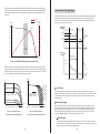
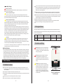
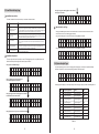
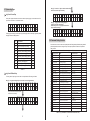
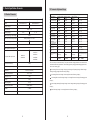
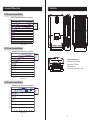
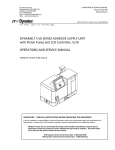
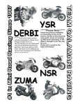
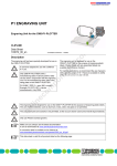
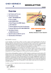
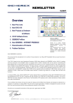
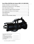
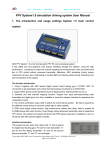
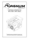
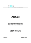
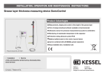
Maximum Power Point
Tracking ML Series
ML4830 & ML4830-LI & ML2440 & ML2440-LI
Solar Charge and Discharge Controller
User Manual
Model
ML4830/ML4830-LI
ML2440/ML2440-LI
Batter y Voltage
12V/24V/36V/48V
12V/24V
Max Solar Input Voltage
150V
150V
Charging Current
30A
40A
Discharging Current
20A
20A
Note: ML4830-LI and ML2440-LI can be used for lithium battery charging
and discharging management.
Material Code:1.1.24.01419
Version: 1.01 The above information is subject to change without prior notice.
Dear user:
Catalog
Thank you for choosing our product !
Safety Instructions
1. Since the adaptable voltage of the solar charge controller exceeds human
safety voltage, you are advised to read instructions before operation
and operate the solar charge controller after completing safe operation
training.
2. There are no parts that need maintaining or repairing inside the solar
charge controller. Users shall not disassemble or repair the controller by
themselves.
3. Please install the solar charge controller indoors, avoid exposure of
components, and prevent water from entering the controller.
4. Please install the solar charge controller in a well-ventilated place, for the
temperature of the cooling fin can be very high during operation.
1. Product Introduction
03
1.1 Product Overview and Features
03
1.2 Product Features
04
1.3 Introduction of the Maximum Power Point Tracking Technology
04
1.4 Introduction of Charging Stages
06
2. Product Installation
07
2.1 Installation Precautions
07
2.2 Wiring Specifications
08
2.3 Installation and Wiring
08
3. Product Operation and Display
11
3.1 LED Indicator
11
3.2 Buzzer
12
3.3 Key Operation
12
3.4 LCD Starting and Main Interface Display
12
3.5 Load Mode Setting Page
15
5. You are recommended to install appropriate insurance or circuit breaker
outside the solar charge controller.
3.6 System Analysis Page
16
3.7 System Log Page
17
6. Before installing or adjusting the connecting wire of the solar charge
controller, make sure that the photovoltaic array wire and insurance or circuit
breaker near battery terminal are disconnected.
3.8 Parameter Setting Interface
18
3.9 Production Information Page
19
7. After installation, check whether all line connections are solid. Bad
connections may cause hazards due to heat accumulation.
Warning: indicates risky operation. Security preparation is required
before operation.
! Note: indicates destructive operation.
Tip: indicates advice and tips for the operator.
01
4. Product Protection Function and System Maintenance
19
4.1 Protection Function Introduction
19
4.2 System Maintenance
20
4.3 Abnormality Display and Alarm
20
21
5. Product Specification Parameter
5.1 Electrical Parameter
21
5.2 Parameter Adjustment Range
22
6. Conversion Efficiency Curve
23
7. Product Size
24
02
1. Product Introduction
1.2 Product Features
1.1 Product Overview and Features
The solar charge controller can monitor generated power of solar panels in real time and track the
highest voltage current value (VI), enabling the system to charge the battery with maximum power
output. Applied to solar off-grid photovoltaic systems, the product coordinates the functions of solar
panels, batteries and loads; and is the core control unit of off-grid photovoltaic systems.
The controller uses liquid crystal for the dynamic display of operation status, operating parameters,
controller logs, historical parameters, and control parameters. Users can check all parameters through
buttons, and modify control parameters according to actual needs so that different system
requirements are met.
The controller adopts standard Modbus communication protocol, making it easy for users to view and
modify system parameters by themselves. We provide free monitoring software, which delivers the
greatest possible convenience for users to satisfy different needs of remote monitoring.
The inside of the solar charge controller is equipped with comprehensive electronic fault self-detecting
function and powerful electronic protection function, therefore avoiding damage to product
components resulting from installation errors and system faults to the greatest extent.
Product Features
Advanced double-peak or multiple-peak tracking technology. When the panel has a shadow block or a
part of the panel is damaged, I-V curve shows multiple peaks. The solar charge controller can still
accurately track the maximum power point.
Built-in algorithm for maximum power tracking. This significantly raises energy utilization efficiency of
photovoltaic systems, with charging efficiency 15% ~ 20% higher than traditional PWM solar charge
controllers.
Combination of multiple tracking algorithms that can track the optimum working point of I-V curve
accurately in a very short period of time.
MPPT tracking efficiency can be as high as 99.9%.
Advanced digital power technology, with circuit energy conversion efficiency as high as 98%.
Supporting charging procedures of gel batteries, sealed batteries, open batteries, lithium batteries and
other types of batteries.①
Current-limiting charging mode. When the power of a solar panel is too large, and the charging current
is greater than rated current, the solar charge controller automatically reduces charging power, thereby
making the solar panel work at rated charging current.
Supporting the start of capacitive load instantaneous large current.
Supporting automatic identification of battery voltage.
LED indicator of malfunction, buzzer alarm, and liquid crystal display of abnormal information. This
helps users identify system failures.
Supporting historical data storage for up to 5 years.
LCD screen display function. The display enables users to view equipment operation data and status,
and modify controller parameters at the same time.
Supporting standard Modbus protocol that meets communication needs on different occasions.
Built-in mechanism of over-temperature protection. When the temperature exceeds the preset value,
the charging current falls linearly with temperature, therefore slowing down the rise of controller
temperature and avoiding controller damage from high temperature.
External battery voltage sampling function. This function prevents line loss from affecting external
battery voltage sampling and ensures greater preciseness of, control parameters.
Temperature compensation functions. Charging and discharging parameters are automatically
adjusted, thereby extending battery service life.
TVS lightning protection.
Note①:Only the ML-LI model supports lithium battery charging and discharging function.
03
Figure 1-1 Solar Charge Controller Appearance and Interface
No.
1
Name
No.
Name
Charging Indicator
10
Battery “-” Interface
2
Battery Indicator
11
Load “-” Interface
3
Load Indicator
12
Battery “+” Interface
4
Abnormality Indicator
13
Load “+” Interface
5
Liquid Crystal Display
14
External Temperature Sampling Interface
6
Operation Button
15
External Battery Voltage Sampling Interface
7
Mounting Hole
16
RS485 Communication Interface
8
Solar Panel “+” Interface
17
RS232 Communication Interface
9
Solar Panel “-” Interface
1.3 Introduction of the Maximum Power Point Tracking Technology
The Maximum Power Point Tracking (MPPT) system is an advanced charging technology that enables
solar panels to output more power by adjusting the working state of electrical modules. Due to the
nonlinearity of a solar array, there is a maximum energy output point (maximum power point) on the
curve of the array. Traditional solar charge controllers (switch charging technology and PWM charging
technology) cannot charge batteries at this point, thus unable to obtain the maximum energy of solar
panels. However, the solar energy charge controller equipped with the MPPT control technology can
track the maximum power point of a solar array at any time in order to gain maximum energy for battery
charging.
Take the 12V system for example. The peak voltage of solar panels (Vpp) is around 17V and battery
voltage is about 12V. Generally, when the solar charge controller is charging a battery, the voltage of
solar panel is maintained at about 12V, indicating that the maximum power is not used. MPPT solar
charge controllers provide a solution to that problem by constantly adjusting the input voltage and
current of solar panels, therefore maximizing input power.
04
Compared with conventional PWM solar charge controllers, MPPT solar charge controllers bring out
the maximum power of solar panels and provide greater charging current. Generally speaking, MPPT
solar charge controllers can improve energy utilization rate by 15% ~ 20% over PWM solar charge
controllers.
1.4 Introduction of Charging Stages
As a stage of charging, MPPT cannot be used separately, but must be combined with charging modes
such as boost charging, floating charging and equalizing charging to complete battery charging
together. A complete charging process includes: fast charging, maintaining charging and floating
charging. The charging curve is as follows:
VP Cur ve
VI Cur ve
I ( A)
5. 0
Battery
Voltage
94. 5
MPPT
4. 5
P( W )
A
B
Bulk Charging
81. 0
4. 0
C
Float Charging
Constant Charging
Equalize
Boost
Boost
ul
k
67. 5
B
3. 5
Float
3. 0
54. 0
Recharge
2. 5
40. 5
2. 0
1. 5
27. 0
PWM
Charging
1. 0
Time
13. 5
0. 5
Battery
Voltage
0. 0
0. 0
2. 8
5. 6
8. 4
11. 2
14. 0
16. 8
19. 6
Duration Time:2h
(Range:10~180min)
U( V )
Cumulative Time:3h
Figure 1-2 Solar Panel Output Characteristic Cur ve
Max Current
Moreover, different environmental temperatures and light conditions lead to frequent changes of the
maximum power point. Our MPPT solar charge controller can constantly adjust parameters according
to different conditions so as to put the system near the maximum working point all the time. The whole
process is completely automatic without any adjustment by users.
Time
I (A)
I ( A)
Figure 1-4 Battery Charging Stage
30℃
40 ℃
Temperature reduces,
current remains constant,
and power increases
Sunlight reduces and current reduces
50℃
60℃
70℃
Solar panel temperature
20℃
Fast Charging
In fast charging stage, battery voltage is below the preset value (equalizing/boost voltage) of full
voltage. The solar charge controller will perform MPPT charging and provide the maximum solar power
to charge battery. After battery voltage reaches the preset value, the controller conducts constantvoltage charging.
Maintaining Charging
U( V )
Sunlight reduces and open circuit voltage reduces
U ( V)
Temperature increases and open circuit voltage reduces
Figure 1-3 Solar Panel Output
Figure 1-4 Solar Panel Output
Characteristic and Lighting Relation
Characteristic and Temperature Relation
When battery voltage reaches the preset value for maintaining voltage, the solar charge controller
performs constant-voltage charging, and this process does not involve MPPT charging. At the same
time, charging current declines gradually over time. There are two stages in maintaining charging,
which are equalizing charging and boost charging. The two charging processes are not repeated
processes. Equalizing charging is started once every 30 days in a month.
Boost Charging
The boost charging stage generally lasts 2 hours by default. Customers can adjust the duration
and preset value of boost voltage according to actual needs. When the duration times reaches the
preset value, the system enters floating charging stage.
05
06
Equalizing Charging
Loose connections and corrosive wires may cause extreme heat that melts wire insulation layers,
burns surrounding materials, or even results in fire. Ensure that connection heads are screwed
tight, and wires are better fixed with tightening belts. Avoid wire shaking and loose connection
heads when moving the application.
Warning: explosion!
Balance opening lead-acid batteries may produce explosive gas, and cabins of the
batteries must be well ventilated.
!
When the system is connected, the output terminal voltage of components can be higher than
human safety voltage. During operation, use insulated tools and make sure your hands are dry.
Attention: equipment damage!
Balance can push up battery voltage to a level that may damage sensitive DC load.
Verification is required to ensure that the allowed input voltage of all system loads is higher than
the set value of equalizing charging for batteries.
!
The battery terminals on the solar charge controller can be connected with one battery or the same
set of batteries. Follow-up instructions in the manual apply to the use of single battery. The same
instructions apply to a system with a set of batteries as well.
Please follow battery manufacturers' safety recommendations.
Attention: equipment damage!
System connecting line is selected according to current density of no greater than 4A/mm2.
Overcharging or too much gas evolution may damage battery plates and cause active
materials on battery plates to fall off. Damages may be caused if equalizing charging voltage is
too high or equalizing charging lasts too long. You are advised to carefully read the specific
requirements on batteries used in the system.
Some types of batteries benefit from regular equalizing charging, which can stir up electrolyte,
equalizing battery voltage, and complete chemical reaction. Equalizing charging boosts battery
voltage to a level higher than standard complement voltage, resulting in gasification of battery
electrolyte. If it is detected that the solar charge controller automatically controls the next
process to perform equalizing charging, equalizing charging duration will be 120 minutes
(default). Equalizing charging and boost charging are not repeated in one full charge process.
This is to avoid too much gas evolution or battery overheating.
Attention:
! When the system cannot maintain battery voltage steadily at constant voltage due to
installation environment or operation with load, the solar charge controller performs time
accumulation until battery voltage reaches the preset value. After the cumulative time reaches
three hours, the system automatically transfers to floating charging.
If the clock of the solar charge controller is not calibrated, the controller performs regular
equalizing charging in accordance with its internal clock.
Connect the solar charge controller grounding terminal to the ground.
2.2 Wiring Specifications
Wiring and installation mode must comply with national and local electrical standard requirements.
Battery and load specifications must be selected according to the rated current. Refer to the following
table for wiring specifications:
Model
Rated Charging Current
Rated Discharging Current
Battery Wire Diameter
Load Line Diameter
ML4830
30A
20A
8 mm 2
5 mm 2
ML2440
40A
20A
10 mm 2
5 mm 2
2.3 Installation and Wiring
Warning: Explosion risk. Do not install the solar
charge controller and open type cell in the same
closed space. Do not install in closed place where
battery gas may gather.
Floating Charging
After a charging stage continues, the solar charge controller reduces battery voltage by decreasing
the charging current, and maintains battery voltage at the preset voltage value for floating charging.
At floating charging stage, the battery undergoes very weak charging to ensure that the battery is in
full charge state. At floating charging stage, the load can obtain nearly all the solar power. If the load
exceeds the power provided by solar energy, the solar charge controller fails to maintain battery
voltage at floating stage. When battery voltage is as low as the preset value for improved recovery
charging, the system exits from floating charging stage and re-enters fast charging stage.
!
Exert great caution during battery installation. Before installing open lead-acid battery, wear
protective goggles. When you are in contract with battery acid liquid, wash the involved part with
water immediately.
Do not place metal objects near battery to prevent short circuit.
When battery is charging, acidic gas can be produced. Ensure that the environment around is well
ventilated.
Attention: When installing a solar charge
controller, make sure there is enough air flowing
through the cooling fin of the controller. Leave a
space of at least 150 mm up and down the solar
charge controller to ensure natural heat loss
through convection. If installed within a closed
cabinet, ensure reliable heat dissipation through
the cabinet body.
Battery may generate combustible gas. Keep it away from sparks.
For outdoor installation, avoid direct sunlight and rain infiltration.
07
Hot Air
≥150mm
Cold Air
Warning: High pressure danger. Photovoltaic
array may generate very high open circuit
voltage. Before wire connection, disconnect the
breaker or insurance. Be careful in the process of
wiring.
2. Product Installation
2.1 Installation Precautions
≥150mm
08
Figure 2-1 Installation and
Heat Dissipation
Step 1: Selecting an installation location.
① External temperature sampling interface connection
Avoid installing solar charge controller in a place where there is direct sunlight, high temperature
or easy water inflow. Ensure the surrounding area of the solar charge controller is well ventilated.
② Battery voltage sampling line connection
Step 2:
③ Communication cable connection
First place installation guide plate at proper position, then use pen and mark on installation
location, drill four installation holes at marked places of suitable size, and fixe with screw.
④ Connect power line
Warning: Risk of electric shock! We strongly recommend access insurance or circuit breaker at
photovoltaic array end, load end and battery end, to prevent electric shock from occurring during
wiring or misoperation. Before wiring, ensure that insurance or circuit breaker is disconnected.
Step 3: Fix the solar charge controller.
On the installation surface, use a pen to mark the positions of four mounting holes, and then move
away solar charge controller. Drill four size-suitable mounting holes at four marked positions, and
fix screws in advance, align fixing holes of solar charge controller to on the four fixed screws, and
then hang it up.
Warning: High pressure danger! Photovoltaic array may generate very high open circuit voltage.
Before wire connection, disconnect the breaker or insurance. Be careful in the process of wiring.
Warning: Risk of explosion. Short circuit of battery positive and negative terminals and wires
connected to them will cause fire or explosion. Please be careful during operation.
Please connect battery first, then connect load, and finally connect the solar panel, please follow
the connection mode of "+" first and then "-".
⑤ Power On
Tip: ML series solar charge controller only starts the solar charge controller via wiring at the
battery end, but ML - LI can start the solar charge controller via power of PV array,. This applies
to starting the solar charge controller and activating lithium battery when lithium battery BMS is
in the protection state and cannot export electricity externally.
When all the power line connections are firm and reliable, recheck whether the wiring is correct,
and whether positive and negative ends are connected reversely. After confirmation, connect
battery fuse or circuit breaker, observe whether LED indicator is lit, and whether LCD screen
displays content. If there is no display, disconnect the fuse or circuit breaker immediately and
recheck whether the circuit connection is correct.
Figure 2-2 Fix the solar charge controller
Step 4: Wiring
If battery is powered on normally, connect the solar panel. If solar charge controller charging
indicators are on normally or flashing, start battery charging.
Remove the two screws on the solar charge controller panel, and then start wiring. For installation
security, we recommend the following wiring sequence. However, wiring without following this
order will not damage the solar charge controller.
When battery and photovoltaic is well connected, then connect load fuse or circuit breaker. At
this time, you can use manual mode to test whether the load On and Off is normal. See load
working mode and operation.
Temp Sense
Warning: When the solar charge controller is under normal charging state, disconnecting
battery connection will affect solar charge controller DC load. In a severe case, the load can be
damaged.
Warning: Within 10 minutes after solar charge controller charging stops, battery reverse polarity
operation may damage internal components of the solar charge controller.
7
!
5
3
6
4
2
1
Attention:
1) Battery insurance installation site should be as close as possible to the battery end.
Recommended installation distance shall be no more than 150 mm.
2) When solar charge controller is not connected to a remote temperature sensor, battery
temperature is a fixed value of 25 ℃.
3) If the inverter is connected in the system, please connect inverter directly with battery, and do
not connect solar charge controller with the load end.
⑥ Close wiring cover
Figure 2-3 Wiring
09
When all wirings of the system are well connected, close the wiring cover and screw screws tight.
10
3. Product Operation and Display
ERROR Indicator
3.1 LED Indicator
PV array Indicator Indicate solar charge controller current charging mode
BAT Indicator
Indicate battery current state.
LOAD Indicator
Indicate load switch and state.
ERROR Indicator
Indicate whether solar charge controller is currently normal working.
Graph
Indication State
Battery State
System Operation No Abnormalities
Steady On
System Abnormal
3.2 Buzzer
PV array Indicator
NO.
Indication State
Off
After abnormality occurs, the buzzer sends out two short and a long buzzing sound.
Buzzer Buzzing State
Abnormality Type
Off
System no abnormalities or buzzing for 1 minute and then stop
Buzzing for 1 minute
Battery Over-Discharge, Under-Voltage, Load Short Circuit,
Over-Load, Solar Controller Over-Temperature, and Battery
Over-temperature
Charging State
①
Steady On
MPPT Charging
②
Slow Flash (On 1s, Off 1s, cycle 2s)
Boost Charging
③
Single Flash(On 0.1s, Off 1.9s, cycle 2s)
Floating Charging
④
Fast Flash(On 0.1s, Off 0.1s, cycle 0.2s)
Equalizing Charging
Double Flash
Current
Buzzing for 15 seconds Battery Under-Voltage
Constant Buzzing
Battery Overvoltage, PV Reverse Connection, PV Overvoltage
3.3 Key Operation
⑤
Up
Menu page up; parameter decrease
under setting mode
Down
Menu page down; parameter increase
under setting mode
Return
Return to the previous menu
(On 0.1s, Off 0.1s, On 0.1s, Off 1.7s, cycle 2s) Limited Charging
⑥
Off
Night
Confirm Enter submenu; Setting/Save key
BAT Indicator
Indication State
Battery State
Steady On
Battery Voltage Normal
Slow Flash(On 1s, Off 1s, cycle 2s)
Battery Over-Discharge
Fast Flash(On 0.1s, Off 0.1s, cycle 0.2s) Battery Overvoltage
3.4 LCD Starting and Main Interface Display
Starting Interface
S t a r t i n g . . .
LOAD Indicator
Indication State
Battery State
Off
Load Not Started
M o d e l
: S R - x x x x x x x
Fast Flash(On 0.1s, Off 0.1s, cycle 0.2s) Overload/Short Circuit
Steady On
Load Normal Output
A U T O V O L T A G E
1 2
2 4
3 6
4 8
11
12
During start, the four indicators flash in flow. LCD starts after self-check. The model of the solar
charge controller is displayed first, and then battery voltage level is displayed. Voltage level is
displayed according to user-selected fixed voltage or voltage automatically identified.
Main Page
Main page has 8 menus, in which menus with sub menus can press setting key to enter next menus
NO.
Page name
Page Note
①
Charging Page Display
Charging state information real-time display, which can display
information of solar panel voltage, charging state, charging current,
battery voltage, and charging power
②
Discharging Load
Information Display Page
Load state information real-time display, which can display
information of battery voltage, load switch state, discharging
current, environment temperature, and discharging power
③
Sub-menu
Yes
Load work mode adjustment page
④
Manual switch load page
The page is available only when load mode is manual mode 15, not
displayed in other modes. In this page, load can be turned on and
off from keys directly.
⑤
System Analysis Page
System analysis page can view charging AH, discharging AH, work
days, and system abnormality information
Yes
System Log Page
Log page can view solar controller historical information up to 5
years at most, including daily min battery voltage, battery max
voltage, daily charging AH, and daily discharging AH, and etc
Yes
⑦
Parameter Setting Page
⑧
Product Information
Parameter settings page can set some parameters of solar
controller, including charging voltage, discharging voltage,
temperature compensation coefficient, communication baud rate,
and etc
Product information can view solar controller serial number and
version information
① Charging Page Display
Solar Panel Voltage
Charging State
Charging Current
1 8 . 0 V
1 2 . 0 V
M P P T
2 4 0 W
2 0 . 0 A
C H R G
Battery Voltage
Charging Power
Charging Page Indicator
L O A D
M O D E
L i g h t + 0 0 H
S E L
④ Switch load page
(can be seen when load mode is manual mode 15)
Load Mode Setting Page
⑥
③ Load Mode Setting Page
L o a d
T u r n
( H o l d
2
O F F
s e c )
⑤ System Analysis Page
D i a g n o s t i c s
M e n u s
S E L
Yes
⑥ System Log Page
Yes
L o g g e d
M e n u s
D a t a
S E L
⑦ Parameter Setting Page
S y s t e m
M e n u s
S e t t i n g s
S E L
⑧ Product Information
② Discharging Display Page
Battery Voltage
Load On/Off State
Discharging Current
1 2 . 0 V
- 1 0℃
O N
1 2 2 W
1 0 . 0 A
L O A D
Environment Temperature
Discharging Power
Discharging Page Indicator
13
P r o d u c t
M e n u s
I n f o
S E L
14
3.5 Load Mode Setting Page
Step ⑤ Long press setting key to save and exit
Setting is successful
Load Mode Introduction
The solar controller has five load work modes,with modes referred as follows:
Code Mode
Description
0
Pure light control
(light on at night, off
during daytime)
When there is no sunlight, the solar panel voltage is below the light control ON
voltage, solar charge controller will open load after delay for a certain time, when
the sunlight appears, solar panel voltage is above light control OFF voltage, solar
charge controller will shut down the load after delay for a certain time
1~14
Light time control for
1~14 hours
When there is no sunlight, the solar panel voltage is below the light control ON
voltage, solar charge controller will open load after delay for a certain time, load
will shut down after working time reaches set value.
15
Manual Mode
16
Debugging Mode
17
Normal Open Mode
L O A D
M O D E
S E T
L i g h t
+
1 7
S E L
Under this mode, the user can control load On and Off through keys, regardless of
daytime or night. This mode is used in some special load situations or used for
debugging.
Used for system debugging, close the load when there is light signal, open load
when there is no light signal, convenient for checking the correctness of the
system installation during installation and debugging.
Power-on load has always maintained output state. This mode is suitable for load
needing 24 hours power supply.
Load Mode Adjustment
The user adjusts load mode according to needs. The debugging mode is set by default (see Load
Mode Introduction). Mode adjustment method goes as follows:
Manual Switch Load Page
The page is available only when load mode is manual mode 15. When load in under manual mode, load
can be turned on and off from following pages manually
Long press the setting key for 2 seconds to turn load on, page displays as follows:
L o a d
T u r n
( H o l d
2
O N
s e c )
Long press the setting key for 2 seconds to turn load off, page displays as follows:
L o a d
T u r n
( H o l d
2
O F F
s e c )
3.6 System Analysis Page
Step ① Enter Load Mode Page
L O A D
M O D E
L i g h t
+
1 6
S E L
Step ② Short press the setting key to
enter mode adjustment interface
L O A D
M O D E
S E T
L i g h t
+
1 6
S E L
Step ③ Long press the setting key for 3 seconds
Load mode will flash at this time
L O A D
M O D E
S E T
L i g h t
+
1 6
S E L
Step ④ Press the +/- key to set needed load mode
In system analysis page, the user can user charging AH, discharging AH, work days, and system abnormality
information, convenient for user to know the working condition of the whole system.
D i a g n o s t i c s
M e n u s
S E L
In this page, press setting key to enter system analysis sub menu page, with page contents as following table 3-6
No.
Displaying Items
Notes
Unit
1
Total Charge WH
Total Charge WH
KWH (度)
2
Total Charge AH
Total Charge AH
KAH
3
Total Dischg WH
Total Dischg WH
KWH (度)
4
Total Dischg AH
Total Dischg AH
KAH
5
Total Work Days
Total Work Days
Days
6
Total LVD Times
Total LVD Times
Times
7
Total FUL Times
Total FUL Times
Times
8
L O A D
M O D E
S E T
L i g h t
+
1 7
S E L
15
Error Code
Error Code
Controller temp
Controller temp
Table 3-6
16
℃
Step ② : Press the +/- key to set the number of days
001 refers to value of previous day
3.7 System Log Page
B A T T E R Y
D A Y:
0 0 1
2 2 . 0 V
M i n
S E L
Log View of Current Day
Some system operation information record can be viewed at system log page, can view data records of five
years at most, see Table 3-7 for information contents
L o g g e d
M e n u s
D a t a
S E L
Step ③ : Long press the setting key for 3
seconds, and save current days
At this time, press +/- key again to view other
log contents of set days
B A T T E R Y
D A Y:
0 0 1
2 6 . 0 V
M a x
S E L
In this page, press setting key to enter system log sub menu page, which is current day’s log data by default,
with page contents as following table 3-7
No.
Log Contents
Unit
1
Battery current day min voltage
V
2
Battery current day max voltage
V
3
Current day max charging current
A
4
Current day max discharging current
A
5
Current day max charging power
W
6
Current day max discharging power
W
7
Current day charging AH
AH
8
Current day discharging AH
9
Current day generating capacity
KWH
10
Current day discharging capacity
KWH
AH
Table 3-7
Log View of Different Days
To view log data of n days ago, the user needs to set a specified date. The setting is as follows:
Step ① : Long press setting key for 3 seconds in current log parameter
B A T T E R Y
D A Y:
0 0 0
2 2 . 0 V
M i n
S E L
Days value start to flash at this time,
000 refers current days
3.8 Parameter Setting Interface
Under this menu, the user can view and set system parameters. Setting shall be performed under guidance of
professional personnel; otherwise, setting error may cause system problems. See table 3-8 For parameter
setting contents
Parameter Setting Contrast Table
No. Displaying Items
1
TYPE OF BAT
Parameter Scope
Battery Type
User/flooded/Sealed/Gel
CAP OF BAT
Battery Capacity
100~3000AH
200AH
3
VOLT OF SYS
System Voltage
12V/24V/36V/48V/AUTO
AUTO
4
OVR VOL DISC
Overvoltage Voltage
9.0 ~ 17.0V
16.0V
5
CHG LMT VOL
Charging Limit Voltage
9.0 ~ 17.0V
15.5V
6
EQUALIZ CHG
Equalizing charging Voltage
9.0 ~ 17.0V
15.2V
7
BOOST CHG
Boost charging Voltage
9.0 ~ 17.0V
14.4V
8
FLOAT CHG
Floating Charging Voltage
9.0~17.0V
13.8V
9
BOOST-RE CHG
Boost charging Recovery to Voltage
9.0~17.0V
12.6V
10 LOW VOL RECT
Over-Discharge Recovery
9.0 ~ 17.0V
12.6V
11 UND VOL WARN
Under-Voltage Warning
9.0 ~ 17.0V
12.0V
12 LOW VOL DISC
Over-Discharge Voltage
9.0 ~ 17.0V
11.0V
13 DISC LMT VOL
Over-Discharge Limit Voltage
9.0 ~ 17.0V
10.5V
14 LVD DELAY
Over-Discharge Delay Time
1 ~ 30s
5s
15 EQUALIZ TIME
Equalizing Charging Duration Time
0 ~ 600Min
120Min
16 BOOST TIME
120Min
10 ~ 600Min
0 ~ 255D ( 0 refers to close
30D
equalizing charging function)
0 ~ 5 ( 0 refers to close
-3mv/℃/2V
Temperature Compensation Coefficient compensation function)
5V
Light Control Voltage
4 ~ 40V
17 AUTO EQUALIZ
18 T-COMP SLOPE
Boost Charging Duration Time
Equalizing Charging Interval
20 L-CON-DELAY
Light Control Delay Time
1 ~ 60Min
5Min
21 BAUD RATE
Communication Baud Rate
1200-115200
9600
22 MODBUS ADDR
Modbus Address
1-250
1
23 RS232 ADDR
RS232 Address
1-65530
1
24 BACK-LIGHT
Back-Light Delay Time
Steady on/10-60Sec
10Sec
25 RESTORE DEFAVLT Restore Factory Default Setting
Table3-8 (All parameters can be set and viewed under User)
17
Default
Paremeters
Sealed
2
19 L-CON-VOL
B A T T E R Y
D A Y:
0 0 0
2 2 . 0 V
M i n
S E L
Notes
18
Chg-P :/%
3.9 Production Information Page
100%
95%
85%
80%
75%
65%
60%
55%
45%
40%
35%
25%
20%
15%
5%
0
You can check the controller model, serial number, software and hardware version etc. to learn about the
product. For detailed information, please see Table 3-9
System Information
No. Name
Item
Parameter Example Example Note
1
Model
Model: ML4830
Solar charge controller model
2
Serial Number
HW:
The 32nd set of October 2015
3
Hardware version SW:
4
Software version
15100032
00.05.00
Hardware version V0.5.0
Serial: 00.03.00
0
Software version V0.3.0
65 66 67 68 69 70 71 72 73 74 75 76 77 78 79
Tem- MOS :/ ℃
Table 3-9
4.2 System Maintenance
4. Product Protection Function and System Maintenance
To maintain the best and long-term performance, it is recommended that following items are
checked each year.
Confirm that air flow around the solar charge controller is not blocked. Remove any dirt or
debris on the cooling fin.
4.1 Protection Function Introduction
Check whether insulation of bare wires is damaged due to sunburn, friction with other objects
around, dry rot, insects or rodents destruction. Check whether repairing or wire replacement is
necessary.
Waterproof Protection
Waterproofing Grade:IP32
Input limit power protection
Verify that indicators are consistent with equipment operation. Please pay attention to any
fault or error displays, and take corrective actions when necessary.
When solar panel power exceeds the rated power, the solar charge controller limits solar panel power within
the scope of rated power to prevent damage of the controller by excessive current, The solar charge
controller enters current limit charging.
Check all wiring terminals to see if there is corrosion, insulation damage, high temperature or
burning /discoloration signs, and tighten screw terminal.
Battery Reverse connection protection
Check whether there are dirt, nest-building insects and corrosion phenomenon, and clean by
following requirements.
When storage system is connected reversely, the system does not work and does not burn out solar charge
controller.
If lightning arrester has failed, timely replace invalid lightning arrester to prevent causing
lightning damage to solar charge controller or even user’s other equipments.
Photovoltaic input terminal voltage too high
Photovoltaic array input voltage is too high, and solar charge controller will automatically cut off PV input.
Warning: Risk of electric shock! In process of above operation, make sure all power supply of
the solar charge controller has been disconnected, and then conduct related check or actions
accordingly!
Photovoltaic input terminal Short circuit protection
After short circuit of photovoltaic array input terminal, the solar charge controller disconnects charging, and
when short circuit condition is removed, charging will be automatically restored.
PV input reverse connection protection
4.3 Abnormality Display and Alarm
When polarity of photovoltaic array is connected reversely, the solar charge controller will not be damaged,
and will continue normal operation after correcting wiring error.
Warning: During reverse connection, battery voltage together with component element voltage must
be less than 150V.
No.
Error Display
Remarks
LED Indication
1
PV REV
Photovoltaic Modules Inversed
Connection
ERROR indicator steady on Buzzer keeps alarming
Load over-power protection
2
PV OVP
Photovoltaic Modules
Overvoltage
ERROR indicator steady on Buzzer keeps alarming
When load exceeds the rated power, delayed load over-power protection will be started according to actual
circumstances.
3
PV_MPP_OVP
Over Set Vmp Voltage
ERROR indicator steady on Buzzer Alarm for 1Min
Load short circuit protection
4
PV OVER CRT
Photovoltaic Modules Overload
ERROR indicator steady on Buzzer Alarm for 1Min
Provide timely and fast protection for short circuit of load, and try to start load automatically after a certain
delay. The maximum number per day is 5 times. When load short circuit occurs, the user can also remove
load short circuit manually in system data analysis page exception code.
5
OVER VOLTAGE
System Overvoltage
6
LOAD SHORT CRT
Load Short Circuit
Night reverse connection proof protection
7
LOAD OVER CRT
At night, prevent battery discharging via solar panel.
9
OVER TMP BAT
TVS Lightning Protection
11
OVER TMP MOS
Environment Temperature
Over-Temperature
Solar Charge Controller Internal
Over-Temperature
Over-Temperature Protection
12
OVER DISCHARGE
Battery Over-Discharge
With temperature higher than the set temperature, the solar charge controller reduces charging power or
stops charging. See the following figure
13
BAT UND VOL WARN Battery Under-Voltage
19
Buzzer Alarm
BAT Indicator fast flash
ERROR indicator steady on Buzzer keeps alarming
LOAD Indicator fast flash
ERROR indicator steady on Buzzer Alarm for 1Min
LOAD Indicator fast flash
Buzzer Alarm for 1Min
ERROR indicator steady on
Overload
ERROR indicator steady on Buzzer Alarm for 1Min
ERROR indicator steady on Buzzer Alarm for 1Min
BAT Indicator slow flash
ERROR indicator steady on Buzzer Alarm for 1Min
ERROR indicator steady on Buzzer Alarm for 15 seconds
20
5. Product Specification Parameter
5.2 Parameter Adjustment Range
5.1 Electrical Parameter
Comparison Table of Parameters for Each Type of Battery
Parameter Value
Parameter Name
Model
System Voltage
ML2440/ ML2440-LI
ML4830/ ML4830-LI
12V/24V Auto
12V/24V/36V/48V Auto
No-Load Loss
Battery Voltage
0.7 W ~ 1.2W
9 ~ 35
9 ~ 70
Max Solar Energy Input Voltage
<150V
Max Power Point Voltage Scope
Battery Voltage +2V ~ 120V
Rated Charging Current
40A
30A
20A
Rated Load Current
10000uF
Max capacitive load capacity
400W/12V
800W/24V
520W/12V
PV System Max Input Power
1200W/36V
1040W/24V
Setting Voltage
Battery Type
Overvoltage
Disconnect Voltage
Sealed Lead-Acid
Battery
16.0V
16.0V
16.0V
9 ~ 17V
Equalizing Voltage
14.6V
——
14.8V
9 ~ 17V
Boost Voltage
14.4V
14.2V
14.6V
9 ~ 17V
Floating Voltage
13.8V
13.8V
13.8V
9 ~ 17V
Boost Restoring
Voltage
13.2V
13.2V
13.2V
9 ~ 17V
Low Voltage Disconnect
Restoring Voltage
12.6V
12.6V
12.6V
9 ~ 17V
Under-Voltage Alarming
Restoring Voltage
12.2V
12.2V
12.2V
9 ~ 17V
Under-Voltage
Alarming Voltage
Low Voltage
Disconnect Voltage
Discharging Limit
Voltage
Over-Discharge
Delay Time
Equalizing Duration
Time
12.0V
12.0V
12.0V
9 ~ 17V
11.1V
11.1V
11.1V
9 ~ 17V
10.6V
10.6V
10.6V
9 ~ 17V
5s
5s
5s
1 ~ 30s
120Min
——
120 Min
Gelled Lead-Acid
Battery
Open Lead-Acid
Battery
Equalizing Charging
Interval
30Days
0Day
30Days
Boost Duration Time
120Min
120Min
120 Min
User (User-Defined)
0 ~ 600 Min
0 ~ 250D (0 refers to
close equalizing charging
function)
10 ~ 600 Min
1600W/48V
The User battery is customized battery. The system’s default voltage parameters are consistent with
sealed lead-acid battery parameters. When modifying battery charging and discharging parameters,
observe the following logic:
≤98%
Conversion Efficiency
>99%
MPPT Tracking Efficiency
Temperature compensation
coefficient
-3mv/℃/2V(Default)
Overvoltage Disconnect Voltage>Charging Limit Voltage≥ Equalizing Voltage≥ Boost Voltage≥
Floating Charging Voltage>Boost Restoring Voltage;
Working Temperature
-35℃ ~ +45℃
Protection Level
IP32
Weight
2.3Kg
Max Wiring Size
25 mm
2
RS485, RS232
Communication Mode
Altitude
≤ 3000m
Product Size
Overvoltage Disconnect Voltage>Overvoltage Disconnect Restoring Voltage;
Low Voltage Disconnect Restoring Voltage>Low Voltage Disconnect Voltage≥ Discharging Limit
Voltage;
Under-Voltage Alarming Restoring Voltage>Under-Voltage Alarming Voltage≥ Discharging Limit
Voltage;
Boost Restoring Voltage>Low Voltage Disconnect Restoring Voltage;
226*182*81mm
21
22
6. Conversion Efficiency Curve
7. Product Size
MPPT 12V System Conversion Efficiency (12V Battery)
20Vmp
40Vmp
60Vmp
90Vmp
110Vmp
20 Vmp
40 Vmp
60 Vmp
90 Vmp
7.5
110 Vmp
40
80
160
240
300
400
500
Output Power (W)
600
700
800
148
182
6.2 24V System Conversion Efficiency
100
40Vmp
60Vmp
80Vmp
90Vmp
110Vmp
96
94
90
88
8XФ10
40 Vmp
81
92
81
60 Vmp
80 Vmp
90 Vmp
110 Vmp
130.56
178
86
82
40
80
160
480
800
Output Power (W)
1200
1600
6.3 48V System Conversion Efficiency
MPPT 48V System Conversion Efficiency (48V Battery)
60Vmp
70Vmp
80Vmp
90Vmp
110Vmp
99
Conversion Efficiency (%)
97 60 Vmp
95
70 Vmp
80 Vmp
93
91
90 Vmp
110 Vmp
89
87
85
160
Technical requirements:
Product size: 266*182*81mm
Hole position:179*160mm
Hole size: Φ4.5mm
Line material used: diameter <10mm
84
80
4XФ4.5
MPPT 24V System Conversion Efficiency (24V Battery)
98
Conversion Efficiency (%)
179
99
98
97
96
95
94
93
92
91
90
89
88
87
86
85
226
Conversion Efficiency (%)
6.1 12V System Conversion Efficiency
160
320
640
1000 1250 1500
Output Power (W)
23
2000
2500
3000
24
4XФ10