1
•
nle
EJektronik fUr den ModeJlbau
EntwickJung, HersteJlung, Vertrieb und Support
SonderlOsungen
---~~
User Manual for GlowControl 5* LiPo
(E:
.. ~.-.~----~-
Status-LED
V3
3hro~~.t!crent
i Seq IIcnee .
.
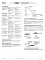
inc!. receiver battery monitor and automatic power
control
flash sequences the status-LED
.
I'DeSC.tiJ'l!ion
.
infor:..:.:m:.:.:e:.:d::.:~...,...~",..,
..
_ .. "
1;.'
'ij
flash cycle 1,5 s . .
receiver voltage on. no glow function
i
flash cycle 0,5 s (2x per, (;Iow function active. throttle po;;ition inside glow I
second)
, raJl.~ _ _ _.._____________- l
I Com;tant tlashcycle 0,25 Start mode active for max. I minute
i s (4x per second)
1Sh00000ash c:'::yc":l::.!e":0"",2"'5::-s--+'-A'-u-t-o""b-oo-s-t-a-c-II:-'v-e"'tiC"or"7
1
I Constant
ON
or : Transmitter is switched OFF or invalid signals.
:flickering
appear. --;---::c;:;;::---;:--::------;- _ _ _..,
Conslant OFF
i Receiver voltage OFF or J I disconnected
i Double /lash every 2,5 s I No signals from the receiver, transmitterOFF
I receiver battery falls below 4,5Vi5,5V. 1'O.r min, 0.5
[Inverted optical image
Thank you for decide on a product from rainbow-tronic. We developed an intelligent system which already satisfied lots of model pilots, Smce we are active model-builders 100 we know where it depends on: Sate technology, universal use, low power consumption, and all this to favourable price, -s------------1
I
I
This manual should help you to take pleasure in and profit from our product. Please read the manual carefully betore use to find the correct contiguration of GlowControl fix your application. GlowControl meets the valid European norms and EMC rules. ~
I
. .~-
• Glow baUer) empty, voltage below 6.2V
No "low battery conncct"d or v~)ltagc below 5,4V :
Description Flash cycle 2.5 s
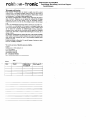
By the lise of GlowControl thc current through the glow plug is adapted to the requirement of the combustion of the motor. This creates a smooth run of the engine in the lower speed range, especially in idle mode, In addition the transition Irom low to high speed is positive intluenced, (;JowControl 5*-UPo is designed for 5- and (;- cylinder engine applications. The necessary battery type is 2 cells IjPo (3.7V per cdl) In addition GlowControl is monitoring the receiver battery and warns the pilot correspondingly, Warning: Ultra-bright special LED,' Do not look direc/ into the light from short distance, It can harm your eyes I Connection of GlowControl 5* LiPo V~
2 Zellenlcells
LiPo I Lilo
von
~ru~g:fr,~,--~~~~::===J'
Functions
I. Connection of GlowControlto 4 or 5 cell receiver batteries possible
without any configuration,
2. The glow haltery should have 2 cells (7AV LiPo) The capacity of the
glow cell depends on the glow time you would like to have (>~ 2000
mAh,150
3. No additional switch necessary in the glow circuit.
4. At GlowControl the glow range can be freely chosen, It is programmed
once and is al"ays present ulltil it will be re-programmed.
5, The AUTOBOOST tunction releases additional l<low energv when 'the'
throttle I~ ~';l;;d;apidly This cares for a good r~sponse orthe engine.
This Ilmction can be disabled via confIguration bridge,
6. GlowControl has a STlili.T.MQI)]; (see later description) which can
help 10 slart the engine or to rc-start a "laz}" cylinder,
7,
In case of reduced glow battery voltage GlowControl automatically
adapt the power to the glow plugs.
8, Via the ullra- bright Status-LED GlowControl informs you about the
actual status, A brief description you will lind below, Please install the
LED in an "easy to sec" position mside the cockpit or in the fuselage,
9, For security reasons the l'J1'>MrSJ functioll keeps (;lowControl in stand
by mode after the receiver voltage is switched on nell if the throttle
stands in idle positioll, To release the glow timction the throttle has to be
moved slighlly.
10, GlowControl monitors the receiver battery voltage. If the voltage falls
below 4.5V (4 cell battery) or 5,5V (5 cell battery) for more than 0.5 s
the status-LED will invert the optical image and keeps it until reset of
battery voltage. The number of cells will be detected automatically
during programming (;lowControl.
11, GlowControl monitors also the glow battery voltage in real time, If the
voltage falls below 3, I V the status-LED will indicate it The glow
function will be aborted,
receiver
~jGlowCont,.oI
. . .'"-"
-t~.~,~,:
J<
----II-....
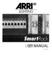
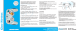
Anschlussschema GlowControl fUr
5-Zylinder Sternmotoren Connection diagram (;lowControl for 5 cyl. radial engines Connect GlowControl to engine and glow battery according 10 the sketch. The stalus-LED should be installed in an "easy-to-see" position inside the cockpit or in the fuselage, For damping of vibration GlowControl should not covered in foam or similar. Please fix it with Dual Lock tape or similar. The GlowContJ'ol unit should be installed most far away from the receiver and the glow plug cable should run direct to the motor and should not cross or run parallel to servo cablcs. Note: In case you connect the ballery and/or the glow plug via terminals please check fi'equently if the screws are ughtened An untightened contact can be responsible for radIO interferences in the receiver system. Detection of receiver battery voltage
GlowControl is equipped with an automatic detection of the no, of cells of the receiver battery pack, The detection in done during the programming of GlowContro\. It has 10 make sure a :i cell battery is above 6V during the programming, Therefore the battery should be fully charged, The no. of detected cells will be indicated during every power-up of GlowControl by the status LED: •
I long pulse
•
4 or 5 short pulses (No. of cells)
•
I long pulse
Operating and control devices
I long
pulse
After programming GlowControl do not need any further handling, Here are
brief descriptions of the COmpL)nents:
4 or 5 pulses
I long pulse s-ul________ ~
On tile board;-----:-:-~_.,..~--;-_:_;_~_ _~~---,--..".,____,
f-'J:..:t'C.=m=-_.__..~+'-"F..;:u:.:cn:.:c;.;ti;.:.l)",n_-I.QescriJl!il>~n_____~ ____.__ ~"'-:-1
Jl
ProgramRelease for programming GlowControL If the
Iming release
f-.c-----, .
• J2
I
---+-1
i:
Note: An empty 5 cell battery could be detected as a 4 cell battery' Please
charge the battery and re-program GlowColltrol,
'jumper is disconnected the programming is ,
I releas~d, when~onne.cte'Lit is mterlocked.
I reler to topic CONFlGURA-;:;T::-I(::-)N:-:-_ _ _~
!Booster
Glow current, referto topic CONFIGURATION . I~J'::'4-.-.
G.:::·7=I\.l.....:..:.:w£lIff~ reterlo!()j)icCONfIGURATION . - - - - 1
T1
Store bullon ~ores the valucs for glow begin and idle I
__________~._________~-wp~oo~sl.tJ~~on~________________________~1
t13
I.
j
A wrong detected receiver battery does not ailect the function of
GlowControl. Just the receiver battery monitor does not indicate correctly.
-
•
ronlc
Elektronik fOr den Modellbau
Entwicklung, Herstellung, Vertrieb und Support
SonderlOsungen
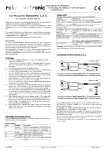
Start-Mode
Because of the unique start-mode of GlowControl you can lift up the glow power to the set maximum (depending of 13 and J4). This can be necessary if your motor will not start in idle position (i.e. needs 113 of throttle) In this position the glow power is already slightly lower than the maximum and your motor possibly will not start. If yOU now activate the start-mode the max. glow power will be present as it normally will be just in idle position. Programming of GlowControl
Activate start-mode You can activate the start-mode: •
Move thc throttle stick 3 times fast forward/retard. The last movement
has to end inside the glow range.
Note: The start-mode can only be active while the throttle stick is inside the
glow range l
Programming
I. Connect GlowControL to the receiver by use of a Y - cable or a free
channel of the receiver with mixer.
2. Switch on the receiver voltage. The status-LED flashes according to the
described sequence.
3. Remove J I. Status-LED stops flashing when throttle stick was moved
after the system was powered on.
4. Put throttle stick in position where glowing should start (ie. 50%)
5. Press button TI at the GLowControl board. The position is stored,
status-LED flashes I time.
6. Move throttle stick into idle position.
7. Press again TI. This position will be stored too. Status-LED flashes 2
times.
S. Replace the jumper J I properly.
9. Switch off the receiver voltage for min. 5 seconds.
10. Finish I The programming is now complete and the stored values are
present after each "power Oil" of the receiver voltage. Are-programming
is, or cause, possible at an) timc.
II. Connect the glow battery with GlowControl. Please take notice of the
polarityl A wrong connection can destroy GlowControl and is no
guarantee case.
12. Place all components inside the fuselage. Please pay also attention to the
centre of gravity.
L3. Please check the range of your radio system (with active glowing) as
you should do it after installation of any electronic device.
Now GlowControl is ready to use.
Cancel start-mode The start-mode can be cancelled in 2 difTerent ways: I. Move the throttle stick out of the glow range
2. Automatic cancellation app. I minute after activation.
Configuration
GlowControl has to be configured before use!
ON
Jumper is set, OFF
Jumper is NOT set.
-+
-+
The jumper 12 sets the boost function I
.Iumper.l2
Configuration
OFF
Boost function enabled
ON
Boost function disabled
GlowControl can be adapted to the required glow power.
J3 and J4 determine the glow power
Jumper J4
Jumper .J3
Configuration
OFr
OFF
80 % glow power
ON
OFr
90 % glow power
OFF
ON
95% glow power
ON
ON
LOO% glow power
Attention: A wrong configuration can destroy your glow plugs! Please
always start configuration with the lowest glow power set up (13+.14 NOT
set)!
In order to save energy the glow power can be reduced. This is depending of
the motor and the environment. Please try to tind out the best configuration
for your application.
Note: A change in contiguration will be accepted after re-power the receiver
voltage!
Preparations
To prepare the programming of GlowControl please program first your
transmitter and all relevant servos, especially the range and direction of the
throttle servo. Connect the glovv plug cables to the engine and set the trim
lever to "0".
Daily start of the engine
•
•
•
•
•
Switch on receiver Voltage. GlowControl do not heat the glow plug at
this time.
As usual draw in the gas. Put the throttle in full speed position. The
status-LED flashes in 1,5 s cyele. Glow function is off Turn the
propeller some revolutions while keeping the carburettor closed.
Move the throttle stick in start position (idle pos.). Glow function is now
active.
Start the engine in the usual way. [s the throttle stick not in idle position
and the glow power is not sufficient activate the START-MODE.
Now you can start your model. On own interest you should warm-up the
engine before start.
Glow battery monitor and power control
Stop the engine at ground
The voltage of the glow battery is monitored in real time mode. In case of
voltage drop the power to the glow plugs will be automatically adapted to
ensure a constant behaviour over the voltage range of the glow battery.
If the voltage drops below 6,2V the glow function will be aborted in order to
save the LiPo cells. To cancel the limitation please move the throttle out of
the glow range.
The status LED will also indicate if no glow battery is connected to
GlowContr·oL. A glow battery with less than 5AV is not detected.
Stop the engine in the usual way:
•
Put the throttle in idle position.
•
Move the trim lever to close the carburettor completely. GlowControl
switches off the glow power. The engine stops. Status-LED flashes
slow.
•
Switch offthe receiver Voltage.
Technical Data GlowControl 5* LiPo
Safety instructions
•
•
•
•
Please note GlowControl heats the glow plug. Turning the propeller
while glowing is active can start the engine. Therefore
Do not reach in the range of the propeller.
Keep children away from the engine.
Switch off the receiver voltage while not using the engine.
04.10.2009
\'3
Receiver voltage
Consumption
Receiver impulse
Receiver connection
3,6V to SV (4 - 5 cells NiCd oder NiMH)
2mA
Positive
Universal connector for FutabaiGraupner, MPX
(other on request)
Connection glow battery Open or 2mm gold plugs
Recommend glow plug All known glow plugs can be used
type
6 (other on request)
No. of glow plugs
No. of cells of glow 2 cells LiPo 7,4V (8,4V max)
battery
Switch-otT voltage glow 6,2V
battery
Min. glow batt. Voltage
5,4V
Version: V3 5* LiPo-O-GB Seite 2 von 4
~
ral
•
ronlc
Elektronik fiir den ModelJbau
Entwieklung, Herstellung, Vertrieb und Support
Sonderlosungen
Trouble shooting
In general GlowControl is a reliable system. In case something do not work
like expected you will lind the cause in the following table:
: I)roblem
i Cause
" A-ct-:-io-I-I--~
"--'-'
I
. . . ._
Status-tEO do not
I Receiver voltage
, Switch on voltage!
,
II tlash
switched olT/ receiver
~teryempt .
: J I not seL
,I
I Chame batten'
,~~
i Set J I proper
,,
Gluhleistllflg
,r:9/ow power-
,
I
Status-LED tlashes,
Glow range not
, Re-program the glow
image do not change , programmed
I range (i.e mid to idle
, whik moving throttle
I position)
i stick via full ran"e
, Status-LED shows
: Glow battery almost
I Charge battery
i correct behaviour plug! emptv
'Y1 ixer for throttle servo Set mixer correctly
do not glow
not set to 100%.
i Status-LED lights
I T ransmitler not
Switch on trallsmitl~
i constantly, flickers or i switched on
• double flash signals
~v 2,5 seconds
Throttle position
After power on the
Move throttle stick
inside glow range but
receiver voltage the
slightly
, no glow power. slatus , throttle stick was not
, LED tlashes slow
moved slightly (safety
funcl1on)
Programmed values
' Jumper J I was not
Remove J I before
removed bet{)re
will not be stor"d
programming
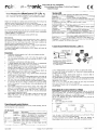
Leerlauf
Idle
Programmierter
Gliihbeginn
Progr. glow beginn
I
I
rogJamrnlng
, Receiver voltage was
, Switch off the receiver
: not interrupted for min. , voltage for min, 5 s
5s
I Engine do not starl
. Throttle stick not in idle If possible move throttle
• even glow battery is
position, glow power is stick closer to idle
fully charged
not sufficient to start
osition
,
cngme
Activate start-mod~e--'"
~--~~~---~~~--~--------+
Status-LED lights up
Receiver voltage was
, Switch off and on again
with short interrupts, • fallen below 4.5V/S.5V 1 will reset this function,
recharge bnllery.
tor more than O.S s
radio system and
Glow<..:ontrol works
Charge glow battery
Glow battery is empty
._1 '
,
I
Status-LED tlashes in
2 second cycle
No glow battery
! dClceted
iGlow batt. connected
i while (~lowControl
i
Connect glow battery
I
: Move throttle stick out of
I glow range temporary.
Vollgas
Full throttle
Connection of additional glow plug
All glow plugs have 10 be connected to GlowControl 5* as seen at the sketch
(ie. cylinder 1-3 to yellow cable, 4-5 plus the additional glow plug to the blue
cable).
For the extra glow plug you will find an angular bracket in the supply range.
Please mount the bracket on a heat resistant surface (no wood) and connect it
electrically with a ground cable (min. I mm2) to the motor block.
In case the extra plug is VIsible after installation you have also an optical
monitor for the glow function.
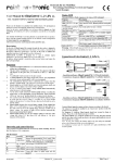
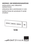
Counectiou of glow plug cable and ground cable
(if in supply range included)
The glow plug cable GI)(~ should be connected to the glow plug as shown in
the sketch. It will be fixed with a locker screw. Because of thermal reasons
please leave a small gap of 0,5 - I mm (app. 0,04") between plug and cable
connector.
The ground cable GC is connected to the engine chassis according to the
-sketch below, To ensure a safe electrical connection please lise a s,'rrated
washer between engine and cable connector.
U.~l:heil:>~L»:asher
- •••'e·i!i•
/!~GC
Facherscheibe ~-.J
serrated washer· • Anschluss GCI
Connection GC
Ansch1uss GPCI
Connection GPC
Handling of the Jumper
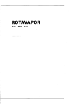
Please handle the jumper with care. Pull and stick them by use of fingers or tweezers. Pick them only at the foreseen tlat end. Keep the unused jumper safe. Definition of glow range
The glow range is calculated by the micro controller from different values, The basic information are the programmed values, GlowControl computes from this the glow range. It starts at the programmed value and ends in idle position plus app.50% of trim range. The "autoboost" functIon can be active also out of glow range. hitzebestandiger
Untergrundl
heat resistant
ground
Einbauvorschlag Zusatz-GIOhkerze
Proposal for installation of auxiliary glow plug