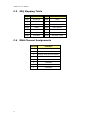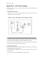
1
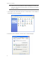
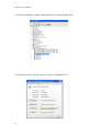
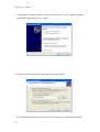
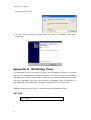
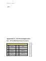
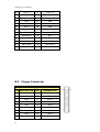
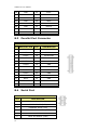
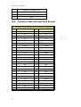
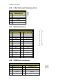
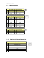
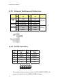
WSB-9150 User Manual WSB-9150 User Manual Version 1.0 SOCKET-478 Pentium 4 Full-Size CPU Card with GbE, LAN, Serial ATA, DVI, and USB2.0 Nov, 2005 ©Copyright 2005 by IEI Electronic Inc. All Rights Reserved. 1 WSB-9150 User Manual Copyright Notice The information in this document is subject to change without prior notice in order to improve reliability, design and function and does not represent a commitment on the part of the manufacturer. In no event will the manufacturer be liable for direct, indirect, special, incidental, or consequential damages arising out of the use or inability to use the product or documentation, even if advised of the possibility of such damages. This document contains proprietary information protected by copyright. All rights are reserved. No part of this manual may be reproduced by any mechanical, electronic, or other means in any form without prior written permission of the manufacturer. Trademarks WSB-9150 is registered trademarks of ICP Electronics Inc.; IBM PC is a registered trademark of International Business Machines Corporation. INTEL is a registered trademark of INTEL Corporation. AMI is registered trademarks of American Megatrends Inc.,Other product names mentioned herein are used for identification purposes only and may be trademarks and/or registered trademarks of their respective companies. Support Any questions regarding the content of this manual or related issue can be e-mailed to us directly at: [email protected] 2 WSB-9150 User Manual Package Contents The WSB-9150 package includes the following items: WSB-9150 Single Board Computer………………………….. X1 RS-232 & Printer Cable with bracket …………………………. X1 ATA IDE cable ……………………………………………………………… X1 SATA IDE cable ……………………………………………………………. X2 SATA Power cord cable…………………………………………………. X1 ATX-12V cable………………………………………………………………. X1 Keyboard and mouse Y-Adapter cable…………………………. X1 Mini Jumper Pack……………………………………………………………X1 USB cable……………………………………………………………………….X1 Driver CD………………………………………………………………………. X1 User manual …………………………………………………………………. X1 If any of these items are missing or damaged, please contact the dealer from whom you purchased this product. Save the shipping materials and carton in case you want to ship or store the product in the future. 3 WSB-9150 User Manual Table of Contents Trademarks.................................................................................2 Support.......................................................................................2 Chapter1 Hardware Configuration.............................................7 1.1 Introduction....................................................................................... 7 1.2 Features............................................................................................ 7 1.3 Specification ...................................................................................... 8 1.4 Jumpers and Connectors.................................................................... 10 1.5 Board Layout: Jumper and Connector Locations .................................... 12 1.6 Block Diagram.................................................................................. 13 1.7 Jumper Settings ............................................................................... 14 1.8 System Memory ............................................................................... 15 1.9 Cache Memory ................................................................................. 16 1.10 Processor Installation ...................................................................... 16 Chapter2 Connecting Peripherals ............................................18 2.1 PCI E-IDE Disk Drive Connector (IDE).................................................. 18 2.2 Floppy Disk Drive Connector (FDD) ..................................................... 18 2.3 Parallel Port (LPT) ............................................................................. 19 2.4 Serial Ports (COM1 & COM2) .............................................................. 19 2.5 IrDA Infrared Interface Port (IR) ......................................................... 20 2.6 DVI Connector (DVI) ......................................................................... 21 2.7 USB Port Connectors (USB1, USB2, USB3, & USB4) ............................... 21 2.8 Keyboard & Mouse Connector (KB/MS & KB) ......................................... 22 2.9 Fan Connectors (CPU_FAN & PWR_FAN) ............................................... 22 2.10 Serial ATA Connectors (S_ATA1, S_ATA2, S_ATA3, & S_ATA4,)............... 23 2.11 External Switches and Indicators (CN1).............................................. 23 2.12 LAN RJ45 Connectors………………………………………………….…………………….………..24 2.13 AC" 97 Connector…………………………………………………………………………………..…….24 2.14 2.14 VGA Connector (VGA…………………….…………………………………………………..25 2.15 ATX Power Button Connector (PW_SW) .............................................. 25 2.16 ATX _12V Power Connector (PW)....................................................... 26 2.17 ATXCTL Connector (ATXCTL)............................................................. 26 Chapter3 AMI BIOS SETUP ......................................................27 3.1 Introduction..................................................................................... 27 3.2 Starting Setup.................................................................................. 27 3.3 Using Setup ..................................................................................... 28 3.4 Getting Help .................................................................................... 28 3.5 BIOS menu bar ................................................................................ 29 4 WSB-9150 User Manual 3.6 Main ............................................................................................... 29 3.7 Advanced ........................................................................................ 30 3.7.1 CPU Configuration .......................................................................... 30 3.7.2 IDE Configuration........................................................................... 31 3.7.3 Floppy Configuration ...................................................................... 33 3.7.4 Super IO Configuration ................................................................... 34 3.7.5 Hardware Health Configuration ........................................................ 34 3.7.6 ACPI Configuration ......................................................................... 35 3.7.7 MPS Configuration.......................................................................... 36 3.7.8 PCI Express Configuration ............................................................... 36 3.7.9 Remote Access Configuration ........................................................... 37 3.7.10 USB Configuration ........................................................................ 38 3.8 PCI PnP ........................................................................................... 38 3.9 Boot ............................................................................................... 40 3.10 Security......................................................................................... 41 3.11 Chipset.......................................................................................... 42 3.11.1 North Bridge Configuration .............................................................. 42 3.11.2 South Bridge Configuration.............................................................. 43 3.12 Power............................................................................................ 44 3.13 Exit............................................................................................... 45 Chapter 4 Chipset Software Installation Utility………………..….46 4.1 Before you begin .............................................................................. 46 4.2 Introduction..................................................................................... 47 4.3 Windows XP Driver Setup................................................................... 47 Chapter 5 VGA Setup (for WSB-9150) ....................................................... 49 5.1 Introduction..................................................................................... 49 5.2 Windows XP Driver Setup................................................................... 49 Chapter 6 LAN Configuration.................................................................... 51 6.1 Introduction..................................................................................... 51 6.2 Windows XP Driver Setup................................................................... 51 Chapter 7 USB 2.0 Configuration .............................................................. 55 7.1 Introduction..................................................................................... 55 7.2 Installation ...................................................................................... 55 Appendix A Watchdog Timer ............................................................... 59 Appendix B I/O Pin Assignments......................................................... 61 B.1 PCI E-IDE Disk Drive Connector .......................................................... 61 B.2 Floppy Connector.............................................................................. 62 B.3 Parallel Port Connector ...................................................................... 63 B.4 Serial Port ....................................................................................... 63 5 WSB-9150 User Manual B.5 Compact Flash Storage Card Socket .................................................. 644 B.6 IrDA Infrared Interface Port ............................................................. 655 B.7 DVI Connector ............................................................................... 655 B.8 USB Port Connector .......................................................................... 65 B.9 LAN Connector ............................................................................... 666 B.10 Keyboard/Mouse Connector .............................................................. 66 B.11 Fan Connector .............................................................................. 677 B.12 Serial ATA Connector ..................................................................... 677 B.13 External Switches and Indicators..................................................... 688 B.14 Audio Connector…………………………………………………………………………………………..68 B.15 VGA Connector ............................................................................... 69 B.17 ATX _12V Power Connector ............................................................ 699 B.18 ATXCTL Connector .......................................................................... 69 Appendix C Address Mapping .............................................................. 70 C.1 IO Address Map................................................................................ 70 C.2 1st MB Memory Address Map.............................................................. 70 C.3 IRQ Mapping Table.......................................................................... 711 C.4 DMA Channel Assignments............................................................... 711 Appendix D ATX Power Supply .......................................................... 722 Appendix E Intel RAID for SATA configuration ................................... 744 6 WSB-9150 User Manual Chapter1 Hardware Configuration 1.1 Introduction Thank you for choosing the WSB-9150 SOCKET 478 PENTIUM 4 Single Board Computer. The WSB-9150 board is a PICMG form factor board, which comes fully equipped with high performance Processor and advanced high performance multi-mode I/O, designed for the system manufacturers, integrators, or VARs that want to provide all the performance, reliability, and quality at a reasonable price. In addition, the GMCH provides an integrated graphics device (IGD) delivering cost competitive 3D, 2D and video capabilities. The GMCH’s analog port uses an integrated 400 MHz RAMDAC that can directly drive a standard progressive scan analog monitor up to a resolution of 2048x1536 pixels with 32-bit color at 85 Hz. WSB-9150 supports one or two 64-bit wide DDR400 data channels. Available bandwidth is up to 3.2GB/s in single-channel mode and 6.4GB/s in dual-channel mode. The single-chip PCI Express based 88E8053 device with a Gigabit Ethernet controller. It supports full 100/1000-base-T Ethernet. It is fully integrated 10BASE-T/100BASE-TX LAN solution with high performance networking functions and low power features. The ICH6 integrates SATA Host Controller, supporting four SATA ports with up to 150MB/s maximum transfer rate. The ICH6R also offers data striping for higher performance (RAID Level 0), and mirroring for Data security (RAID Level 1). For applications that need high-speed serial transmission, WSB-9150 provides eight USB2.0 ports for your convenience. The high speed USB2.0 host controller implements an ECHI interface that provides bandwidth up to 480Mb/s. 1.2 Features Intel long term support product Intel P4 / Prescott / Celeron CPU supports up to FSB 800 MHz Intel GMA900 graphic accelerator Dual channel DDR400 SDRAM memory support High performance PCI Express Gigabit Ethernet controller 7 WSB-9150 User Manual 1.3 Specification General Specifications CPU: Intel Socket-478 P4/Prescott/Celeron-D up to 800 MHz FSB Interface: PICMG 1.0 compliant, PCI 2.1 Chipset: Intel 915GV and ICH6/ICH6R. BIOS: AMI Bios System memory: Two 184-pin DIMM sockets support Dual Channel DDR333/400 SDRAM, support one or two 64-bit wide DDR data channels. The maximum memory is up to 2 GB. Installing two identical DIMMs in pairs will result in Dual Channel operations, which theoretically will double the memory bandwidth. Enhanced IDE interface: Supports up to 2 PCI Enhanced IDE hard drives. The Ultra DMA 100 IDE can handle data transfer up to 100 MB/s, compatible with existing ATA IDE specifications. Serial ATA: Intel ICH6 integrates 4 SATA interfaces with transfer rate up to 150MB/s. It supports RAID 0, 1. Real Time Clock: Intel ICH6 built-in RTC with Lithium battery Hardware monitor: Built-in to monitor CPU Vcore, Vcc, CPU/System fan speed and temperature detecting function. 8 WSB-9150 User Manual Display Chipset: Intel 915GV GMCH (Graphic Memory Controller Hub), which integrates Intel® Graphics Media Accelerator (GMA) 900. It supports widescreen LCD displays and accelerated DirectX* 9. Onboard SDVO chip (SIL1362) supports color DVI display (optional). Connector: DB-15 connector for VGA display on rear I/O panel Ethernet Chipset: Marvell 88E8053 Gigabit Ethernet controller supports full 100/1000-base-T Ethernet. Connector: Dual RJ-45 connectors with LED on rear I/O panel Multi I/O Ports Chipset: Intel ICH6 with ITE IT8712F Super I/O controller Serial ports: Two RS-232 ports by pin-header. Ports can be individually configured to COM1, COM2 or disabled. Bi-directional parallel port: One LPT port, supports EPP/ECP/SPP parallel mode FDD port: One FDD port, supports up to two floppy disk drives, 5.25” (360KB and 1.2MB) and/or 3.5” (720KB, 1.44MB and 2.88MB). IrDA port: Supports Serial Infrared (SIR) and Amplitude Shift Keyed IR (ASKIR) interface USB port: Supports eight USB 2.0 ports, by pin-headers Watchdog timer: Software Programmable Reset, automatically generated when CPU does not periodically trigger the timer (hung). PS/2 Keyboard and Mouse: PS/2 Keyboard/Mouse connector on rear I/O panel. Expansion Slot Compact Flash: Type II socket 9 WSB-9150 User Manual Audio Audio: Realtek ALC655 AC’97 Audio CODEC, 16-bit, full-duplex AC'97 Rev. 2.3 compatible six-channel audio CODEC designed for PC multimedia systems. Connector: Line-out connector on rear I/O panel and CD-in, line-out, mic-in pin-headers Power Consumption & Environment Power consumption: Pentium 4 Northwood 3.0GHz CPU (2GB DDR400 DDR-SDRAM): [email protected], [email protected], [email protected], [email protected]. Pentium 4 Prescott 3.4GHz CPU (2GB DDR400 DDR-SDRAM): [email protected], [email protected], [email protected], [email protected]. Power Supply: 350-Watt power supply or higher is recommended. Power control function: meets ACPI 1.1 specification. Operating Temperature: 0 ℃ ~ 60 ℃ (*CPU needs Cooler & silicone heat sink paste) Relative Humidity: 5%~95%, non condensing WARNING: 1. Never run the processor without the heat sink and CPU Fan. 2. Be sure to connect ATX_12V power connector (PW) for the CPU power. 1.4 Jumpers and Connectors Jumpers on WSB-9150 can be used to set the system configuration according to your application. WSB-9150 is also equipped with Connectors that allow you to connect external devices such as HDD, FDD, K/B, Printer, etc. The tables below list the function of jumpers and connectors on WSB-9150. Jumpers 10 Label Function CLR_CMOS Clear CMOS Setup JP1 Compact Flash Master/Slave Function Setting WSB-9150 User Manual Connectors Label Function Remark IDE Ultra ATA100 Primary & 40-pin shrouded header Secondary IDE connectors FDD Floppy connector LPT Parallel port connector COM2 Serial port connector DB-9 connector COM1 Serial port connector 10-pin shrouded header IR IRDA infrared interface port 5-pin unshrouded header DVI DVI connector USB1 USB dual port connector 8-pin unshrouded header USB2 USB dual port connector 8-pin unshrouded header USB3 USB dual port connector 8-pin unshrouded header USB4 USB dual port connector 8-pin unshrouded header LAN LAN RJ45 connector RJ-45 with LED KB/MS 34-pin shrouded header 6-pin Mini-Din Keyboard & Mouse PS/2 fixed rear panel mount connector KB External 5-pin Header Keyboard 5-pin Header Connector CPU_FAN FAN connector 3-pin friction lock headers PWR_FAN FAN connector 3-pin friction lock headers S_ATA1 Serial ATA connector 7-pin vertical headers S_ATA2 Serial ATA connector 7-pin vertical headers S_ATA3 Serial ATA connector 7-pin vertical headers S_ATA4 Serial ATA connector 7-pin vertical headers F_PANEL1 External switches and indicators 14-pin unshrouded header J_LANLED1 LAN1 LED connectors RJ-45 connector VGA VGA connector HBD-15 connector PW ATX _12V Power connector 4-pin keyed header ATXCTL Backplane to Main board ATX 3-pin friction lock headers power control Connector 11 WSB-9150 User Manual 1.5 12 Board Layout: Jumper and Connector Locations WSB-9150 User Manual 1.6 Block Diagram Intel Socket 478 Pentium PWM-ISL6556I 4 Supporting VCORE HT Technology Clock Generator PWM-ISL6537I OTHER CHANNEL A Intel 915GV SDVO-DVI GMCH DDR SDRAM DIMM X 1 CHANNEL B DDR SDRAM DIMM X 1 IDE PRIMARY 8 Hi Speed USB 2.0 Intel ICH 6 4 SERIAL ATA Ports PCI SLOT FWH/HWM PCI EXPRESS GIGA LAN LPC ITE8712HX COMA COMB LPT PS2 IR FDD WINBOND FRONT PANNEL / CPU FAN AC 97 13 WSB-9150 User Manual 1.7 Jumper Settings This section provides instructions on how to configure WSB-9150 by setting the jumpers. It also includes WSB-9150’s default settings and options for each jumper. 1.7.1 How to set jumpers A jumper is a metal bridge that closes an electrical circuit. It consists of two metal pins and a small metal clip (often protected by a plastic cover) that slides over the pins to connect them. To CLOSE/SHORT a jumper means connecting the pins of the jumper with the plastic clip and to OPEN a jumper means removing the plastic clip from the jumper. Note: The default jumper setting is marked in GREY color. 1.7.2 CMOS clear (CLR_CMOS) In case WSB-9150 fails to boot due to user’s improper BIOS setting, CLR_CMOS jumper can be used to clear the CMOS data and reset the system BIOS information by shorting pin 2-3 for few seconds and then moving the jumper back to pin 1-2. If WSB-9150 shows “CMOS Settings Wrong” message during the boot up, press F1 to go into the CMOS Setup menu. You may then enter the correct CMOS setting or Load Optimal Defaults or Load Failsafe Defaults. Save your changes and exit the CMOS Setup menu. Note: 1. In normal operation, pin 1-2 must stay in CLOSED condition. 2. Power must be turned OFF before clearing CMOS data 14 CLR_CMOS DESCRIPTION 1-2 (Normal Operation) WSB-9150 User Manual 2-3 1.7.3 Clear CMOS Setup Compact Flash Master/Slave Function Setting (JP1) JP1 can be used to set the Compact Flash as Master (OPEN) or Slave (CLOSE). 1.8 JP1 DESCRIPTION OPEN Slave CLOSE Master System Memory WSB-9150 has two 184-pin DIMM sockets for a maximum total memory module up to 2GB 2.5V DDR SDRAM. Dual Channel Technology is applied only when two same modules are used. Installing two identical DIMMs results in dual-channel operation mode, which will double the memory bandwidth to 6.4GB/s. To install memory module, first make sure the two handles of the DIMM socket are in the "open" position (the handles lean outward). Slowly slide the DIMM module along the plastic guides on both ends of the socket, then press the DIMM module right down into the socket, until you hear a ‘click’ sound. This is when the two handles have automatically locked the memory module into the correct position of the DIMM socket. To remove the memory module, just push both handles outward, and the memory module will be ejected by the mechanism in the socket. 15 WSB-9150 User Manual 1.9 Cache Memory Since the second-level (L2) cache has been embedded into the Intel® socket 478 Pentium® 4/Celeron processor, you do not have to take care of either SRAM chips or SRAM modules. The built-in second-level cache in the processor yields much higher performance than the external cache memories. The cache size in the Intel Pentium 4 processor 3.0GHz, for example, is 1024 KB. 1.10 Processor Installation The WSB-9150 is designed for Intel Pentium® 4 processor/Celeron (socket 478) Step 1: 16 WSB-9150 User Manual Lift the processor socket lever Step 2: Align the corner having the triangle marking on the processor with the corner where the lever is attached to the socket Step 3: Lower the lever to its original position 17 WSB-9150 User Manual Chapter2 Connecting Peripherals (please, see Appendix B for detail pin assignments) 2.1 PCI E-IDE Disk Drive Connector (IDE) You can attach up to two IDE (Integrated Drive Electronics) drives to the WSB-9150’s built-in controller. WSB-9150’s Ultra DMA100 IDE supports data transfer up to 100MB/s. Ultra DMA 100 IDE drive must be equipped with Ultra DMA 100 cable, for optimum performance. IDE1: IDE Interface Connector 2.2 Floppy Disk Drive Connector (FDD) You can attach up to two floppy disk drives to the WSB-9150’s onboard controller. You can use 3.5" (360KB, 720KB, 1.2MB, 1.44MB and 2.88MB) drives. The motherboard comes with a 34-pin daisy-chain drive connector cable. On one end of the cable is a 34-pin flat-cable connector. On the other end are two sets of 34-pin flat-cable connector (usually used for 3.5" drives). The set on the end (after the twist in the cable) connects to the A: floppy drive. The set in the middle connects to the B: floppy drive. Please connect the red power connector wire to the pin1 position. FDD1: 18 FDC Connector WSB-9150 User Manual 2.3 Parallel Port (LPT) Usually, a printer is connected to the parallel port. The WSB-9150 includes an on-board parallel port, accessed via a 26-pin flat-cable connector LPT. LPT1 : Parallel Port Connector 2.4 Serial Ports (COM1 & COM2) The WSB-9150 offers two high speed NS16C550 compatible UART’s with 16-byte Read/Receive FIFO serial ports. COM1: 10-pin external connector 19 Connector Ports Address Interrupt COM1 COM1 3F8 IRQ4 5 4 3 2 1 ● ● ● ● ● ● ● ● ■ ● 10 9 8 7 6 WSB-9150 User Manual COM2: 9-pin external connector Connector Ports Address Interrupt COM2 COM2 2F8 IRQ3 1 5 9 • COM2 : Serial Port Connector 2.5 IrDA Infrared Interface Port (IR) The product has a built-in IrDA port which supports Serial Infrared (SIR) or Amplitude Shift Keyed IR (ASKIR) interface. If you want to use the IrDA port, you have to configure SIR or ASKIR model in the BIOS under Peripheral Setup COM2. Then the normal RS-232 COM 2 will be disabled. IR1: IrDA connector 20 WSB-9150 User Manual 5 ● 2.6 4 ● 3 ● 2 ● 1 ■ DVI Connector (DVI) The WSB-9150 provides DVI interface for your DVI display. 2.7 USB Port Connectors (USB1, USB2, USB3, & USB4) The WSB-9150 provides up to four USB (Universal Serial Bus) ports, which gives complete Plug & Play and hot swapping for up to 127 external devices. The USB interface complies with USB Specification Rev. 2.0 support transmission rate up to 480 Mbps and is fuse-protected. The USB interface can be disabled in the system BIOS setup. • USB1~USB4 : Internal USB Connector 21 WSB-9150 User Manual 2.8 Keyboard & Mouse Connector (KB/MS & KB) The WSB-9150 has a 6-pin DIN keyboard/mouse connector (KB/MS). For alternative application, a keyboard pin header connector (KB) is also available on board, located on KB respectively. KB/MS1 : 6-pin Mini-DIN Keyboard Connector 6 4 5 3 2 1 2.9 Fan Connectors (CPU_FAN & PWR_FAN) The WSB-9150 also has a CPU with cooling fan connector and chassis fan connector, which can supply 12V/500mA to the cooling fan. There is a “rotation” pin in the fan connector, which transfers the fan’s rotation signal to the system BIOS in order to recognize the fan speed. Please note that only some specific types of fans offer a rotation signal. 22 WSB-9150 User Manual CPU_FAN1 : Fan Connector 321 2.10 Serial ATA Connectors (S_ATA1, S_ATA2, S_ATA3, & S_ATA4,) The WSB-9150 provides four Serial ATA ports (S_ATA1, S_ATA2, S_ATA3, and S_ATA4) to connect with Serial ATA devices. Serial ATA can provide data transfer rate up to 150MB/s. Serial ATA also provides Hot-Plug support, lower pin-count, lower signaling voltage, easier cabling and CRC Error Detection. Please refer to the BIOS setting for the Serial ATA and install the proper driver in order to work properly. S_ATA1~S_ATA4 : Serial ATA Connector 7 2.11 1 External Switches and Indicators There are several external switches and indicators for monitoring and controlling your CPU board. All functions are in the CN1 connector. 23 WSB-9150 User Manual F_Panel1 : External Switches and Indicators panel 13 11 9 7 5 3 1 ● ● ● ● ● ● ■ ● ● ● ● ● ● ● 14 12 10 8 2.12 6 4 2 LAN RJ45 Connectors (J_LANED1) The WSB-9150 is equipped with one built-in 10/100Mbps (LAN1) & one built-in 100/1000Mbps (LAN2) Ethernet controllers. You can connect it to your LAN through RJ45 LAN connectors. There are two LED on the connector (CN2 & CN3) indicating the status of LAN. 2.13 AC’97 Connector (J_AUDIO1) The product does not build in AC’97 AUDIO CODEC; It needs to connect to the AUDIO CODEC module. CN3: AC’97 Connector 24 WSB-9150 User Manual 2.14 9 7 5 3 ● ● ● ● ● ● ● ■ ● ● 1 10 8 6 4 2 VGA Connector (VGA) The WSB-9150 includes a VGA interface that can drive conventional CRT displays. It is a standard 15-pin D-SUB connector commonly used for VGA. • VGA1: 15-pin Female Connector 2.15 ATX Power Button Connector (F_PANEL1) Connect a power ON/OFF switch to this connector. 25 WSB-9150 User Manual 2.16 ATX _12V Power Connector (PW) The ATX_12V power connector mainly supplies power to the CPU. If the ATX_12V power connector is not connected, the system will not start. This connector supports the ATX-12V power. 2.17 ATXCTL Connector (ATXCTL) Connect this connector to the ATX Control Connector of your backplane. ATXCTL1: Backplane to Main board Connector 26 WSB-9150 User Manual Chapter3 AMI BIOS SETUP 3.1 Introduction This manual describes AMI's Setup program, which is built into the ROM BIOS. The Setup program allows users to modify the basic system configuration. This special information is then stored in battery-backed RAM so that it retains the Setup information when the power is turned off. 3.2 Starting Setup The AMI BIOS is immediately activated when you first power on the computer. The BIOS reads the system information contained in the CMOS and begins the process of checking out the system and configuring it. When it finishes, the BIOS will seek an operating system on one of the disks and then launch and turn control over to the operating system. While the BIOS is in control, the Setup program can be activated in one of two ways: 1. By pressing <Del> immediately after switching the system on, or 2. by pressing the <Del>key when the following message appears briefly at the bottom of the screen during the POST. Press DEL to enter SETUP. If the message disappears before you respond and you still wish to enter Setup, restart the system to try again by turning it OFF then ON or pressing the "RESET" button on the system case. You may also restart by simultaneously pressing <Ctrl>, <Alt>, and <Delete> keys. If you do not press the keys at the correct time and the 27 WSB-9150 User Manual system does not boot, an error message will be displayed and you will again be asked to... 3.3 Using Setup In general, you use the arrow keys to highlight items, press <Enter> to select, use the PageUp and PageDown keys to change entries, press <F1> for help and press <Esc> to quit. The following table provides more detail about how to navigate in the Setup program using the keyboard. Up arrow Move to previous item Down arrow Move to next item Left arrow Move to the item in the left hand Right arrow Move to the item in the right hand Esc key Main Menu -- Quit and not save changes into CMOS Status Page Setup Menu and Option Page Setup Menu -- Exit current page and return to Main Menu Page Up key Increase the numeric value or make changes Page Dn key Decrease the numeric value or make changes F1 key General help, only for Status Page Setup Menu and Option Page Setup Menu F2 /F3 key Change color from total 16 colors. F2 to select color forward. F10 key 3.4 Save all the CMOS changes, only for Main Menu Getting Help Press F1 to pop up a small help window that describes the appropriate keys to use and the possible selections for the highlighted item. To exit the Help Window press <Esc> or the F1 key again. If, after making and saving system changes with Setup, you discover that your computer no longer is able to boot, the AMI BIOS supports an override to the CMOS settings that resets your system to its defaults. The best advice is to only alter settings that you thoroughly understand. To this end, we strongly recommend that you avoid making any changes to the chipset defaults. These defaults have been carefully chosen by both AMI and your systems 28 WSB-9150 User Manual manufacturer to provide the absolute maximum performance and reliability. Even a seemingly small change to the chipset setup has the potential for causing you to use the override. 3.5 BIOS menu bar The menu bar on top of the screen has the following main items: Main For changing the basic system configuration. Advanced For changing the advanced system settings. PCI PnP This entry appears if your system supports PnP / PCI. Boot For changing the system boot configuration. Security Use this menu to set User and Supervisor Passwords. Chipset For changing the chipset setting. Power For changing the advanced power management configuration. Exit 3.6 For selecting the exit options and loading default settings. Main When you enter the BIOS Setup program, the Main menu screen shows the basic system information. AMI BIOS This part shows the auto-detected BIOS information. Processor This part shows the auto-detected CPU specification. System Memory This part shows the auto-detected system memory. System Time [HH:MM:SS] It shows the current time. You may set the time according to your local time. System Date [Day MM/DD/YYYY] This item allows you to set the system date. 29 WSB-9150 User Manual 3.7 Advanced The Advanced menu items allow you to change the settings for the CPU and other system devices. aWarning: Don’t do any change to the BIOS setting, unless you understand the impact thoroughly. The default setting has been carefully chosen/set by both AMI and your system manufacturer to provide the absolute maximum performance and reliability. Setting wrong values in some critical section may cause system to malfunction. 3.7.1 CPU Configuration This sub menu shows the CPU-related information, which is detected by BIOS. User may set the CPU operating speed with following options: 30 WSB-9150 User Manual Max CPUID Value Limit: [Disabled] Enable this item to boot legacy Operating System that cannot support CPU with extended CPUID function. If your Operating System is NT, this item must be set to [Enabled]. Configuration options: [Disabled] [Enabled] Hardware Prefetcher: [Disabled] A third mechanism used to reduce the time waiting for DRAM is through a hardware-prefetching scheme. The hardware prefetcher looks for streams of data and tries to predict what data will be needed next by the processor and proactively tries to fetch these data. All Intel Pentium 4 processors contain a hardware prefetcher that can prefetch both code and data streams, where the data stream can be accessed by loads and/or stores. Adjacent Cache Line Prefetch [Disabled] This menu allows you to enable or disable the adjacent cache line prefetch mode. Configuration options: [Disabled] [Enabled] Hyper-Threading Technology [Enabled] This item allows you to enable or disable the processor Hyper-Threading Technology. This technology allows a single processor supporting Hyper-Threading Technology presents itself to modern operating systems and applications as two virtual processors. The processor can work on two sets of tasks simultaneously; use resources that otherwise would sit idle, and get more work done in the same amount of time. Configuration options: [Disabled] [Enabled] IDE Configuration The items in this menu allow you to set or change the configurations for the IDE devices installed in the system. Select an item then press Enter if you wish to configure the item. 31 WSB-9150 User Manual ATA/IDE Configuration [Compatible] This item allows you to configure the ATA/IDE. Configuration options: [Disabled] [Compatible] [Enhanced] Legacy IDE Channels [SATA Pri, PATA Sec] Primary and Secondary IDE Master/Slave While WSB-9150 is turned ON, the BIOS auto detects the presence of IDE devices. This menu, when entered, shows detail information of the IDE devices (Device type, Vendor, Size, LBA Mode, Block Mode, PIO Mode, Async DMA, Ultra DMA, and SMART monitoring). This information is auto-detected by BIOS and is not user-configurable. It will show "Not Detected” if no IDE device is installed in the system. Type [Auto] Selects the type of IDE drive. Setting to Auto allows automatic selection of the appropriate IDE device type. Select CDROM if you are specifically configuring a CD-ROM drive. Select ARMD (ATAPI Removable Media Device) if your device is either a ZIP, LS-120, or MO drive. Configuration options: [Not Installed] [Auto] [CDROM] [ARMD] LBA/Large Mode [Auto] Enables or disables the LBA (Logical Block Addressing)/Large mode. Setting to Auto enables the LBA mode if the device supports this mode, and if the device was not previously formatted with LBA mode disabled. Configuration options: [Disabled] [Auto] Block (Multi-sector Transfer) [Auto] Enables or disables data multi-sectors transfers. When set to Auto, the data transfer from and to the device occurs multiple sectors at a time if the device supports multi-sector transfer feature. When set to Disabled, the data transfer from and to the device occurs one sector at a time. Configuration options: [Disabled] [Auto] PIO Mode [Auto] IDE Programmed I/O (PIO) Mode programs the timing cycle between IDE drive and the programmable IDE controller. As PIO mode increases, the cycle time decreases. Select [Auto] to let AMIBIOS select the PIO mode. If you select a specific value for the PIO mode, you must be absolutely sure that the value you are selecting is 32 WSB-9150 User Manual supported by the IDE being configured. Configuration options: [Auto] [0] [1] [2] [3] [4] DMA Mode [Auto] Selects the DMA mode for the device. Configuration options: [Auto] [SWDMA0] [SWDMA1] [SWDMA2] [MWDMA0] [MWDMA1] [MWDMA2] [UDMA0] [UDMA1] [UDMA2] [UDMA3] [UDMA4] [UDMA5] SMART Monitoring [Auto] SMART stands for Smart Monitoring, Analysis, and Reporting Technology. It allows AMIBIOS to use the SMART protocol to report server system information over a network. Configuration options: [Auto] [Disabled] [Enabled] 32Bit Data Transfer [Disabled] Enables or disables 32-bit data transfer. If the host controller does not support 32-bit data transfer, this menu must be set to [Disabled] Configuration options:[Disabled] [Enabled] Hard Disk Write protect [Disabled] This menu allows you to enable or disable the hard disk write protect. Configuration options: [Disabled] [Enabled] IDE Detect Time Out (Sec) [35] Selects the time out value for detecting ATA/ATAPI devices. Configuration options: [0] [5] [10] [15] [20] [25] [30] [35] ATA(PI) 80Pin Cable Detection [Host & Device] This menu allows you to configure the mechanism for detecting 80-pin ATA(PI) cable. Configuration options: [Host & Device] [Host] [Device] 3.7.3 Floppy Configuration Floppy A [1.44 MB 3½”] Select the type of floppy drive connected to WSB-9150. Configuration options: [Disabled][360K, 5.25”][1.2M, 5.25”][720K, 3.5”] [1.44M, 3.5”] [2.88M, 3.5”] 33 WSB-9150 User Manual Floppy B [Disabled] Select the type of floppy drive connected to WSB-9150. Configuration options: [Disabled][360K, 5.25 in.][1.2M, 5.25 in.][720K, 3.5 in.] [1.44M, 3.5 in.] [2.88M, 3.5in.] 3.7.4 Super IO Configuration On Board Floppy Controller [Enabled] Allow you to enable or disable the floppy disk controller. Configuration options: [Disabled] [Enabled] Floppy Drive Swap [Disabled] Configuration options: [Disabled] [Enabled] Serial Port1 Address [3F8/IRQ4] Allow you to select the Serial Port1 base address. Configuration options: [Disabled] [3F8/IRQ4] [3E8/IRQ4] [2E8/IRQ3] Serial Port2 Address [2F8/IRQ3] Allow you to select the Serial Port2 base address. Configuration options: [Disabled] [2F8/IRQ3] [3E8/IRQ4] [2E8/IRQ3] Parallel Port Address [378] Allow you to select the Parallel Port base addresses. Configuration options: [Disabled] [378] [278] [3BC] Parallel Port Mode [Normal] Allow you to select the Parallel Port mode. Configuration options: [Normal] [Bi-directional] [EPP] [ECP] Parallel Port IRQ [IRQ7] Configuration options: [IRQ5] [IRQ7] 3.7.5 Hardware Health Configuration This screen shows you the CPU, System and Power temperature, Fan speed and CPU core voltage. It also allows your to configure the Hardware Health Monitoring. H/W Health Function [Enabled] 34 WSB-9150 User Manual To enable/disable H/W Health function FAN1 Mode Setting [Full On Mode] To configure Fan mode as Full On, Automatic or PWM Manually mode. 3.7.6 ACPI Configuration This menu is used to change the settings for the Advanced Power Management (APM). Select an item then press Enter to display the configuration options. ACPI Aware O/S 35 WSB-9150 User Manual This menu allows you to enable or disable ACPI support for Operating System. Select [Yes] is OS supports ACPI and select [No] is OS does not support ACPI. Configuration options: [Yes] [No] General ACPI Configuration This menu configures the general ACPI setting. Advanced ACPI Configuration Use this section to configure additional ACPI options. It contains below sub-menus: ACPI 2.0 Features [No] This menu allows you to enable or disable RSPD pointers to 64-bit Fixed System Description Tables. Configuration options: [No] [Yes] ACPI APIC support [Enabled] This menu allows you to enable or disable the ACPI support in the ASIC. When set to Enabled, the ACPI APIC table pointer is included in the RSDT pointer list. Configuration options: [Disabled] [Enabled] AMI OEMB table [Enabled] Allow you to enable or disable the inclusion of the BIOS -> AML exchange pointer to R(X)SDT pointer lists. Configuration options: [Disabled] [Enabled] Headless mode [Disabled] Allow you to enable or disable headless operation mode through ACPI. Chipset ACPI Configuration It contains chipset ACPI related Configuration settings. You may enable or disable the APIC ACPI SCI IRQ. 3.7.7 MPS Configuration This menu allows you to configure MPS Revision [1.4] Configuration options: [1.1] [1.4] 3.7.8 PCI Express Configuration This menu allows you to enable or disable the PCI express link power states. Configuration options: [Enable] [Disable] 36 WSB-9150 User Manual 3.7.9 Remote Access Configuration This menu allows you to enable or disable Remote Access. Configuration options: [Disabled] [Enabled]. If you choose [Enable], below sub menus will show up: Serial port number [COM1] This menu allows you to select the serial port for console redirection. Make sure the selected port is enabled. Configuration options: [COM1] [COM2] Serial Port Mode [115200 8,n,1] This menu allows you to select serial port settings. Configuration settings: [115200 8,n,1] [57600 8,n,1] [38400 8,n,1] [19200 8,n,1] [09600 8,n,1] Flow Control [None] This menu allows you to select flow control for console redirection Configuration options: [None] [Hardware] [Software] Redirection After BIOS POST This menu allows you to set Redirection configuration after BIOS POST. You may turn off the redirection after POST [Disable] or set the Redirection to be active during POST and Boot Loader [Boot Loader] or to set the Redirection to be always active [Always] Configuration options: [Disable] [Boot Loader] [Always] Terminal Type [ANSI] This menu allows you to select the target terminal type. Configuration options: [ANSI] [VT100] [VT-UTF8] VT-UTF8 Combo Key Support [Disabled] This menu allows you to enable or disable VT-UTF8 combination key support for ANSI/VT100 terminals. Configuration options: [Disabled] [Enabled] 37 WSB-9150 User Manual 3.7.10 USB Configuration The items in this menu allow you to change the USB-related features. Select an item then press Enter to display the configuration options. USB Function [8 USB Ports] Allow you to set the number of USB ports to activate. Configuration options: [Disabled] [2 USB Ports] [4 USB Ports] [6 USB Ports] [8 USB Ports] Legacy USB Support [Enable] Enable support for legacy USB/ older USB devices. Configuration options: [Disabled] [Enabled] USB 2.0 Controller [Enabled] Allow you to enable or disable the USB 2.0 controller. Configuration options: [Disabled] [Enabled] 3.8 PCI PnP The PCI PnP menu items allow you to change the advanced settings for PCI/PnP devices. The menu includes setting IRQ and DMA channel memory size block for legacy ISA devices. aWarning: Don’t do any change to the PCIPnP setting, unless you understand the impact thoroughly. Setting wrong values may cause system to malfunction. 38 WSB-9150 User Manual Clear NVRAM [NO] Clear NVRAM during system boot. Plug & Play O/S [NO] This menu is to configure whether or not the Operating System installed is Plug & Play aware. AMIBIOS detects and enables PnP card, which is required for system boot. Select [No] if the Operating System (like OS/2, DOS) does not support PnP. Configuration options: [No] [Yes] PCI Latency Timer [64] This menu allows you to select the value in units of PCI clocks for the PCI device latency timer register. Configuration options: [32] [64] [96] [128] [160] [192] [224] [248]. Allocate IRQ to PCI VGA [Yes] When set to [Yes], BIOS assigns an IRQ to PCI VGA card if the card requests for an IRQ. When set to [No], BIOS does not assign an IRQ to the PCI VGA card even if requested. Configuration options: [No] [Yes] Palette Snooping [Disabled] When set to [Enabled], the palette snooping feature informs the PCI devices that an ISA graphics device is installed in the system so that the device can function correctly. Setting to [Disabled] deactivates this feature. Configuration options: [Disabled] [Enabled] PCI IDE Bus Master [Disabled] If set to [Enabled], AMIBIOS is allowed to use PCI bus mastering when reading/writing to IDE devices. Configuration options: [Disabled] [Enabled] Off Board PCI/ISA IDE Card [Auto] Some PCI IDE cards may require this to be set to the PCI slot number that is holding the card. It is to specify the PCI slot number where the off-board PCI IDE controller is installed. Configuration options: [Auto] [PCI Slot1]~[PCI Slot6] IRQ xx [Available] When set to [Available], the specified IRQ is available for use by PCI/PnP devices. When set to [Reserved], the IRQ is reserved for legacy ISA devices. Configuration options: [Available] [Reserved] DMA Channel # [Available] When set to [Available], the specified DMA is available for use by PCI/PnP devices. When set to [Reserved], the specified DMA is reserved for legacy ISA devices. Reserved Memory Size [Disabled] This is to set the size of memory block to be reserved for legacy USB devices. 39 WSB-9150 User Manual Configuration options: [Disabled] [16k] [32k] [64k] 3.9 Boot The Boot menu items allow you to change the system boot options. Select an item then press Enter to display the sub-menu. Boot Settings Configuration It is used to configure system boot setting with below submenus: Quick Boot [Enabled] Enabling this item allows BIOS to skip some Power On Self Tests (POST) while booting to decrease the time needed to boot the system. When set to [Disabled], BIOS performs all the POST items. Configuration options: [Disabled] [Enabled] Quiet Boot [Disabled] This allows you to enable or disable the full screen logo display feature. Configuration options: [Disabled] [Enabled] LAN Boot ROM support [Disabled] This allows you to enable or disable the LAN boot function. Configuration options: [Disabled] [Enabled] Add On ROM Display Mode [Force BIOS] Sets the display mode for option ROM. Configuration options: [Force BIOS] [Keep Current] Bootup Num-Lock [On] Allow you to select the power-on state for the NumLock. Configuration options: [Off] [On] PS/2 Mouse Support [Auto] Allow you to enable or disable support for PS/2 mouse. Configuration options: [Disabled] [Enabled] [Auto] Wait for ‘F1’ If Error [Enabled] When set to Enabled, the system waits for F1 key to be pressed when error occurs. Configuration options: [Disabled] [Enabled] Hit ‘DEL’ Message Display [Enabled] 40 WSB-9150 User Manual When set to Enabled, the system displays the message ‘Press DEL to run Setup’ during POST. Configuration options: [Disabled] [Enabled] Interrupt 19 Capture [Disabled] When set to [Enabled], this function allows the option ROMs to trap Interrupt 19. Configuration options: [Disabled] [Enabled] Boot Device Priority This menu is used to specify the boot device priority sequence. Hard Disk Drives This menu is used to specify the boot device priority sequence from available Hard Disk Drives. Removable Drives This menu is used to specify the boot device priority sequence from available removable drives. CD/DVD Drives This menu is used to specify the boot device priority sequence from available CD/DVD drives. 3.10 Security The Security menu items allow you to change the system security settings. Select an item then press Enter to display the configuration options. Change Supervisor Password Select this item to set or change the supervisor password. The Supervisor Password item on top of the screen shows the default Not Installed. After you have set a password, this item shows Installed. Change User Password Select this item to set or change the user password. The User Password item on top of the screen shows the default Not Installed. After you have set a password, this 41 WSB-9150 User Manual item shows Installed. Boot Sector Virus Protection [Disabled] Allow you to enable or disable the boot sector virus protection. If enabled, AMI BIOS will issue a warning when a virus or program attempts to write to the HDD’s boot sector or attempts to execute Disk Format command. Note: you must disable this function when formatting a HDD. Configuration options: [Disabled] [Enabled] 3.11 Chipset The Chipset menu items allow you to change the advanced chipset settings. Select an item then press Enter to display the sub-menu. aWarning: Don’t do any change to the Advanced Chipset Settings, unless you understand the impact thoroughly. Setting wrong values may cause system to malfunction. 3.11.1 North Bridge Configuration 42 WSB-9150 User Manual DRAM Frequency [Auto] This menu allows you to configure DRAM Frequency. Configuration options: [Auto] [333MHz] [400MHz] Configure DRAM Timing by SPD [Enabled] When this item is enabled, the DRAM timing parameters are set according to the DRAM SPD (Serial Presence Detect). When disabled, you can manually set the DRAM timing parameters through the DRAM sub-items. Configuration options: [Disabled] [Enabled] Memory Hole [Disabled] Configuration options: [Disabled] [15MB-16MB] Boots Graphic Adapter Priority [PCI/IGD] Allows selection of the graphics controller to use as primary boot device. Configuration options: [Internal VGA] [PCI/Int-VGA] Internal Graphics Mode Select [Enable, 8MB] Select the amount of system memory used by the internal graphics device. Configuration options: [Enable, 1MB] [Enable, 4MB] [Enable, 8MB] [Enable, 16MB] [Enable, 32MB] Aperture Size Select [256MB] Allow you to select the size of mapped memory for AGP graphic data. Configuration options: [4MB] [8MB] [16MB] [32MB] [64MB] [128MB] [256MB] Video Function Configuration DVMT Mode Select [Combo Mode] Configuration options: [Fixed Mode][DVMT Mode][Combo Mode] Boot Display Device [CRT+EFP] Allow you to select the boot display device. Configuration options: [CRT][EFP][CRT+EFP] 3.11.2 South Bridge Configuration 43 WSB-9150 User Manual Azalia/AC’97 Selection [Enable] Allow you to enable or disable the AC’97 Audio. Configuration options: [Enable] [Disabled] PRO-NIC Controller [Enable] Allow you to enable or disable the onboard 10/100 LAN device. Configuration options: [Enable] [Disabled] Giga LAN Controller [Enable] Allow you to enable or disable the onboard Giga LAN device. Configuration options: [Enable] [Disabled] Spread Spectrum Mode [Disable] Allow you to enable or disable the spread spectrum modulation. Configuration options: [Enable] [Disabled] Restore on AC Power Loss [Last State] When set to [Power Off], the system goes into off state after an AC power loss. When set to [Power On], the system goes on after an AC power loss. When set to [Last State], the system goes into either off or on state Whatever the system was state before the AC power loss. Configuration options: [Power Off] [Power On] [Last State] 3.12 Power Power Type Select [ATX] Allow you to select the power type mode. Configuration options: [ATX] [AT] Power Management/APM [Enabled] Allow you to enable or disable the Advanced Power Management (APM) feature. Configuration options: [Disabled] [Enabled] 44 WSB-9150 User Manual Video Power Down Mode [Suspend] Allow you to select the video power down mode. Configuration options: [Disabled] [Standby] [Suspend] Hard Disk Power Down Mode [Suspend] Allow you to select the hard disk power down mode. Configuration options: [Disabled] [Standby] [Suspend] Standby Time Out [Disabled] Allow you to select the specified time at which the system goes on standby. Configuration options: [Disabled] [1 Min] [2 Min] [4 Min] [8 Min] [10 Min] [20 Min] [30 Min] [40 Min] [50 Min] [60 Min] Suspend Time Out [Disabled] Allow you to select the specified time at which the system goes on suspend. Configuration options: [Disabled] [1 Min] [2 Min] [4 Min] [8 Min] [10 Min] [20 Min] [30 Min] [40 Min] [50 Min] [60 Min] Power Button Mode [On/Off] Allows the system to go into On/Off mode or suspend mode when the power button is pressed. Configuration options: [On/Off] [Suspend] Resume On Ring [Disabled] Allow you to enable or disable RI to generate a wake event. Configuration options: [Disabled] [Enabled] Resume On LAN [Disabled] Allow you to enable or disable LAN GPI to generate a wake event. Configuration options: [Disabled] [Enabled] Resume On PME# [Disabled] Allows you to enable or disable PCI PME# to generate a wake event. Configuration options: [Disabled] [Enabled] Resume On RTC Alarm [Disabled] Allow you to enable or disable RTC to generate a wake event. When this item is set to Enabled, the items RTC Alarm Date, RTC Alarm Hour, RTC Alarm Minute, and RTC Alarm Second appear with set values. Configuration options: [Disabled] [Enabled] 3.13 Exit The Exit menu items allow you to load the optimal or failsafe default values for the BIOS items, and save or discard your changes to the BIOS items. 45 WSB-9150 User Manual Save Changes and Exit Once you are finished making your selections, choose this option from the Exit menu to ensure the values you selected are saved to the CMOS RAM. The CMOS RAM is sustained by an onboard backup battery and stays on even when the PC is turned off. When you select this option, a confirmation window appears. Select [Yes] to save changes and exit. Discard Changes and Exit Select this option only if you do not want to save the changes that you made to the Setup program. If you made changes to fields other than system date, system time, and password, the BIOS asks for a confirmation before exiting. Discard Changes This option allows you to discard the selections you made and restore the previously saved values. After selecting this option, a confirmation appears. Select [Yes] to discard any changes and load the previously saved values. Load Optimal Defaults This option allows you to load optimal default values for each of the parameters on the Setup menus, which will provide the best performance settings for your system. F9 key can be used for this operation. Load Failsafe Defaults This option allows you to load failsafe default values for each of the parameters on the Setup menus, which will provide the most stable performance settings. F8 key can be used for this operation. Chapter 4 Chipset Software Installation Utility 4.1 Before you begin To facilitate the installation of the enhanced display device drivers and utility software, you should read the instructions in this chapter carefully before you attempt installation. The device drivers for the WSB-9150 board are located on the software installation CD. The auto-run function of the driver CD will guide and link you to the utilities and device drivers under a Windows system. The Intel Chipset Software Installation Utility is not required on any systems running Windows NT 4.0. Updates are provided via Service Packs from Microsoft. Note: The files on the software installation CD are compressed. Do not attempt to install the drivers by copying the files manually. You must use the supplied SETUP program to install the drivers. Before you begin, it is important to note that most display drivers need to have the 46 WSB-9150 User Manual relevant software application already installed in the system prior to installing the enhanced display drivers. In addition, many of the installation procedures assume that you are familiar with both the relevant software applications and operating system commands. Review the relevant operating system commands and the pertinent sections of your application software’s user’s manual before performing the installation. 4.2 Introduction The Intel Chipset Software Installation (CSI) utility installs to the target system the Windows INF files that outline to the operating system how the chipset components will be configured. This is needed for the proper functioning of the following features: Core PCI and ISA PnP services AGP support IDE Ultra ATA 100/66/33 interface support USB 1.1 support (USB 2.0 driver needs to be installed separately) Identification of Intel chipset components in the Device Manager Integrates superior video features. These include filtered sealing of 720 pixel DVD content, and MPEG-2 motion compensation for software DVD Note: This utility is used for the following versions of Windows system, and it has to be installed before installing all the other drivers: Windows 98SE Windows 2000 Windows Me Windows XP 4.3 Windows XP Driver Setup 1. Insert the driver CD into your system’s CD-ROM drive. In a few seconds, the software installation main menu appears. Move the mouse cursor over the "Auto" button under the "CSI UTILITY" heading, a message pops up telling you to install the CSI utility before other device drivers. Click on this button. Taking Windows XP as example. 2. Click "Next" when you see the following message. 47 WSB-9150 User Manual 3. Click "Yes" when you see the following message. 4. Click "Next" when you see the following message. 5. When the following message appears, click "Finish" to complete the installation 48 WSB-9150 User Manual and restart Windows. Chapter 5 VGA Setup (for WSB-9150) 5.1 Introduction The WSB-9150 has VGA onboard, you need to install the VGA driver to enable the function. The Intel 915GV Express chipset, designed for the Intel Pentium 4 processor supporting Hyper-Threading Technology, in the LGA775 package, delivers a decade's worth of innovation: Intel Graphics Media Accelerator (GMA) 900, which supports widescreen LCD displays and accelerated DirectX* 9 Intel High Definition Audio and Intel Matrix Storage Technology integrated into the chipset Flexible memory support for both dual channels DDR2 533 memory, which can deliver up to 8.5 GB/s bandwidth 5.2 Windows XP Driver Setup Note: Before installing this driver, make sure the CSI utility has been installed in your system. See Chapter 4 for information on installing the CSI utility Insert the driver CD into your system’s CD-ROM drive. In a few seconds, the software installation main menu appears, as shown in the following figure. Under the "VGA DRIVERS" heading, click on one of the buttons (labeled "W2K XP", "WIN9X ME", and "WIN NT" respectively) according to the operating system you are using. 49 WSB-9150 User Manual The following installation procedure is for Windows XP. For other operating systems, please follow the on-screen installation guide. 1. You will see a welcome window. Please chick on "Next" to continue the installation. 2. Click "Yes" when you see the following message. 3. Click "Finish" to complete the installation and restart the computer now or later. 50 WSB-9150 User Manual Chapter 6 LAN Configuration 6.1 Introduction The WSB-9150 features the 32-bit 10/100/1000 Mbps Ethernet network interface. This interface supports bus mastering architecture and auto-negotiation features. Therefore standard twisted-pair cabling with RJ-45 connectors for 10 Mbps, 100 Mbps and 1000 Mbps connections can be used. Extensive driver support for commonly used network systems is also provided. 6.2 Windows XP Driver Setup Note: Before installing the LAN drivers, make sure the CSI utility has been installed in your system. See Chapter 4 for information on installing the CSI utility. The WSB-9150’s onboard Ethernet interface supports all major network operating systems. However, the installation procedure varies with different operating systems. In the following sections, refer to the one that provides driver setup procedure for the operating system you are using. 1. From Windows XP, select Start and click on Control Panel. In the window of Control Panel, click on icon System. 51 WSB-9150 User Manual 2. Choose the option "Hardware", and then click on "Device Manager". 3. In Device Manager, choose "Ethernet Controller" and then double click. 52 WSB-9150 User Manual 4. Choose the option "Driver" and then click on "Update Driver". 5. In Hardware Update Wizard, choose "Install from a list or specific location (Advanced)" and then click on " Next". 53 WSB-9150 User Manual 6. Tick "Search removable media (floppy, CD-ROM…)" and click "Next". 7. In the following window, please click on "Finish" to complete USB driver installation. 54 WSB-9150 User Manual Chapter 7 USB 2.0 Configuration 7.1 Introduction The WSB-9150 is designed with Intel ICH6 that supports both USB1.1 and USB 2.0 high-speed transmission. It still remains the compatibility with today’s USB device. High-speed USB 2.0 provides data transfer up to 480Mb/s which is 40 times faster than USB 1.1. It is ideal for today’s speed-demanding I/O peripherals. Provides data transmission rate up to 480Mb/s Offer 40 greater bandwidth than USB 1.1 Offers complete compatibility with current USB device 7.2 Installation Note: Before installing this driver, make sure the CSI utility has been installed in your system. See Chapter 4 for information on installing the CSI utility. 55 WSB-9150 User Manual Note: USB 2.0 driver is not available for Windows 98SE/ME from WSB-9150 driver CD. Under these operating systems, the USB device will operate at USB 1.1 speeds. 1. From Windows XP, select Start and click on Control Panel. In the window of Control Panel, click on icon System. 2. Choose the option "Hardware", and then click on "Device Manager". 56 WSB-9150 User Manual 3. In Device Manager, choose "USB Controller" and then double click. 4. Choose the option "Driver" and then click on "Update Driver". 57 WSB-9150 User Manual 5. In Hardware Update Wizard, choose "Install from a list or specific location (Advanced)" and then click on " Next". 6. Tick "Include this location in the search" and click "Next". 7. In the following windows, please specify the location "D:\USB20\Intel\WinXP" 58 WSB-9150 User Manual and then click on "OK". 8. In the following window, please click on "Finish" to complete USB driver installation. Appendix A Watchdog Timer The Watchdog Timer is provided to ensure that standalone systems can always recover from catastrophic conditions that cause the CPU to crash. This condition may have occurred by external EMI or a software bug. When the CPU stops working correctly, Watchdog Timer will either perform a hardware reset (cold boot) or a Non-Maskable Interrupt (NMI) to bring the system back to a known state. A BIOS function call (INT 15H) is used to control the Watchdog Timer: INT 15H: AH – 6FH 59 WSB-9150 User Manual Sub-function: AL – 2: Set the Watchdog Timer’s period BL : Time-out value(Its unit--second is dependent on the item “Watchdog Timer unit select” in CMOS setup). You have to call sub-function 2 to set the time-out period of Watchdog Timer first. If the time-out value is not zero, the Watchdog Timer will start counting down. While the timer value reaches zero, the system will reset. To ensure that this reset condition does not occur, calling sub-function 2 must periodically refresh the Watchdog Timer. However, the Watchdog timer will be disabled if you set the time-out value to be zero. A tolerance of at least 10% must be maintained to avoid unknown routines within the operating system (DOS), such as disk I/O that can be very time-consuming. Note: When exiting a program it is necessary to disable the Watchdog Timer, otherwise the system will reset. Example program: ; INITIAL TIMER PERIOD COUNTER ; W_LOOP: MOV AX, 6F02H ;setting the time-out value MOV BL, 30 ;time-out value is 48 seconds INT 15H ; ; ADD YOUR APPLICATION PROGRAM HERE ; 60 CMP EXIT_AP, 1 JNE W_LOOP ;is your application over? ;No, restart your application MOV AX, 6F02H ;disable Watchdog Timer MOV BL, 0 ; INT 15H WSB-9150 User Manual ; ; EXIT ; Appendix B I/O Pin Assignments B.1 PCI E-IDE Disk Drive Connector IDE: IDE Connector PIN DESCRIPTION PIN DESCRIPTION 1 RESET# 2 GND 3 DATA 7 4 DATA 8 5 DATA 6 6 DATA 9 7 DATA 5 8 DATA 10 9 DATA 4 10 DATA 11 11 DATA 3 12 DATA 12 13 DATA 2 14 DATA 13 61 WSB-9150 User Manual 15 DATA 1 16 DATA 14 17 DATA 0 18 DATA 15 19 GND 20 N/C 21 DRQ 22 GND 23 IOW# 24 GND 25 IOR# 26 GND 27 CHRDY 28 REV. PULL LOW 29 DACK 30 GROUND-DEFAULT 31 INTERRUPT 32 N/C 33 SA1 34 N/C 35 SA0 36 SA2 37 HDC CS0# 38 HDC CS1# 39 HDD ACTIVE# 40 GND B.2 Floppy Connector FDD: Floppy Connector PIN DESCRIPTION PIN DESCRIPTION 1 GND 2 RWC0- 3 GND 4 NC 5 GND 6 RWC1- 7 GND 8 INDEX- 9 GND 10 MO-A 11 GND 12 DS-B 13 GND 14 DS-A 15 GND 16 MO-B 17 GND 18 DIR- 62 WSB-9150 User Manual 19 GND 20 STEP- 21 GND 22 WD- 23 GND 24 WGATE- 25 GND 26 TRK0- 27 GND 28 WP- 29 GND 30 RDATA- 31 GND 32 HEAD- 33 GND 34 DSKCHG- B.3 Parallel Port Connector LPT: Parallel Port Connector PIN DESCRIPTION PIN DESCRIPTION 1 STROBE# 14 AUTO FORM FEED # 2 DATA0 15 ERROR# 3 DATA1 16 INITIALIZE 4 DATA2 17 PRINTER SELECT LN# 5 DATA3 18 GND 6 DATA4 19 GND 7 DATA5 20 GND 8 DATA6 21 GND 9 DATA7 22 GND 10 ACKNOWLEDGE 23 GND 11 BUSY 24 GND 12 PAPER EMPTY 25 GND 26 NC 13 PRINTER SELECT B.4 Serial Port COM1, COM2: 10Pin Serial Port Connector PIN DESCRIPTION 1 DATA CARRIER DETECT (DCD) 2 RECEIVE DATA (RXD) 3 TRANSMIT DATA (TXD) 4 DATA TERMINAL READY (DTR) 5 GND 6 DATA SET READY (DSR) 63 WSB-9150 User Manual 7 REQUEST TO SEND (RTS) 8 CLEAR TO SEND (CTS) 9 RING INDICATOR (RI) 10 GND B.5 Compact Flash Storage Card Socket CF: Compact Flash Storage Card Socket pin assignment PIN DESCRIPTION PIN DESCRIPTION 1 GND 26 PULL DOWN 2 D3 27 D11 3 D4 28 D12 4 D5 29 D13 5 D6 30 D14 6 D7 31 D15 7 CS1# 32 CS3# 8 N/C 33 N/C 9 GND 34 IOR# 10 N/C 35 IOW# 11 N/C 36 VCC 12 N/C 37 IRQ15 13 VCC 38 VCC 14 N/C 39 MASTER/SLAVE 15 N/C 40 N/C 16 N/C 41 RESET# 17 N/C 42 IORDY 18 A2 43 N/C 19 A1 44 VCC 20 A0 45 ACTIVE# 21 D0 46 PDIAG# 22 D1 47 D8 23 D2 48 D9 24 N/C 49 D10 50 GND 25 64 PULL DOWN WSB-9150 User Manual B.6 IrDA Infrared Interface Port IR: IrDA connector PIN DESCRIPTION 1 VCC 2 NC 3 IR-RX 4 GND 5 IR-TX B.7 DVI Connector DVI: DVI Connector PIN DESCRIPTION PIN DESCRIPTION 1 DATA2- 14 VCC 2 DATA2+ 15 NC 3 GND 16 HP_DET 4 NC 17 DATA0- 5 NC 18 DATA0+ 6 DDCCLK 19 GND 7 DDCDATA 20 NC 8 NC 21 NC 9 DATA1- 22 GND- 10 DATA1+ 23 CLK+ 11 GND 24 CLK- 12 NC 25 GND 13 NC B.8 USB Port Connector USB1, USB2, USB3, UBS4: 2 ports USB Connector PIN DESCRIPTION PIN DESCRIPTION 1 VCC 2 GND 3 DATA0- 4 DATA1+ 5 DATA0+ 6 DATA1- 7 GND 8 VCC 65 WSB-9150 User Manual B.9 LAN Connector CN2: LAN1 State LED Connector PIN DESCRIPTION PIN DESCRIPTION 1 SPEED- 2 SPEED+ 3 LINK- 4 ACT+ LAN2: 100/1000 LAN RJ45 Connector PIN DESCRIPTION PIN DESCRIPTION 1 TX0+ 2 TX0- 3 TX1+ 4 TX1- 5 VCC 6 GND 7 TX2+ 8 TX2- 9 TX3+ 10 TX3- 11 SPEED1000- 12 SPEED100+ 13 LINK- 14 ACT+ CN3: LAN2 State LED Connector PIN DESCRIPTION PIN DESCRIPTION 1 SPEED1000- 2 SPEED100+ 3 LINK- 4 ACT+ B.10 Keyboard/Mouse Connector KB/MS: Mini DIN Keyboard/Mouse Connector PIN DESCRIPTION 1 KEYBOARD DATA 2 MOUSE DATA 3 GND 4 +5V 5 KEYBOARD CLOCK 6 MOUSE CLOCK 66 WSB-9150 User Manual KB: 5-pin Header Keyboard Connector PIN DESCRIPTION 1 KEYBOARD CLOCK 2 KEYBOARD DATA 3 N/C 4 GND 5 +5V B.11 Fan Connector CPU_FAN, PWR_FAN: Fan Connector PIN DESCRIPTION 1 GND 2 +12V 3 Rotation Signal B.12 Serial ATA Connector S_ATA1, S_ATA2, S_ATA3, S_ATA4: Serial ATA Connector 67 PIN DESCRIPTION 1 GND 2 S_TXP 3 S_TXN 4 GND 5 S_RXP 6 S_RXN 7 GND WSB-9150 User Manual B.13 External Switches and Indicators PI DESCRIPTIO PI DESCRIPTIO N N N N Power LED 1 +5V 2 +5V 3 N/C 4 N/C 5 GROUND 6 N/C PWRBTSW- 8 Speaker GROUND 10 N/C +5V 12 Reset- HDLED- 14 GND PWRBTN 7 9 HDDLED 11 13 B.14 Speaker RESET AC’97 Connector PIN NO. DESCRIPTI ON PIN NO. DESCRIPT ION 1 SYNC 2 BITCLK 3 SDOUT 4 PCBEEP 5 SDIN 6 RST# 7 VCC 8 GND 9 +12V 10 GND 9 7 5 3 1 ● ● ● ● ● ● ● ■ ● ● 10 8 6 4 2 The product does not has a built-in AC’97 AUDIO CODEC; It needs to connect to the AUDIO CODEC module. 68 WSB-9150 User Manual B.15 VGA Connector VGA: 15-pin Female Connector PIN DESCRIPTION PIN DESCRIPTION B.16 1 RED 2 GREEN 3 BLUE 4 NC 5 GND 6 GND 7 GND 8 GND 9 VCC / NC 10 GND 11 NC 12 DDC DAT 13 HSYNC 14 VSYNC 15 DDCCLK ATX _12V Power Connector PW: ATX_12V Power Connector PIN DESCRIPTION PIN DESCRIPTION 1 GND 2 GND 3 +12V 4 +12V B.17 ATXCTL Connector ATXCTL: Backplane to Mainboard Connector PIN DESCRIPTION 1 5VSB 2 ATX-ON 3 GND ★ Power source from Backplane with ATX Connector (Through Power Button & +5VSB) 69 WSB-9150 User Manual Appendix C Address Mapping C.1 IO Address Map I/O address Description Range C.2 000-01F DMA Controller 020-021 Interrupt Controller 040-043 System time 060-06F Keyboard Controller 070-07F System CMOS/Real time Clock 080-09F DMA Controller 0A0-0A1 Interrupt Controller 0C0-0DF DMA Controller 0F0-0FF Numeric data processor 1F0-1F7 Primary IDE Channel 2F8-2FF Serial Port 2 (COM2) 378-37F Parallel Printer Port 1 (LPT1) 3B0-3BB Intel(R) 82915 Graphics Controller 3C0-3DF Intel(R) 82915 Graphics Controller 3F6-3F6 Primary IDE Channel 3F7-3F7 Standard floppy disk controller 3F8-3FF Serial Port 1 (COM1) 1st MB Memory Address Map *Default setting 70 Memory address Description 00000-9FFFF System memory A0000-BFFFF VGA buffer F0000-FFFFF System BIOS 1000000- Extend BIOS WSB-9150 User Manual C.3 IRQ Mapping Table IRQ0 System Timer IRQ8 RTC clock IRQ1 Keyboard IRQ9 ACPI IRQ2 Available IRQ10 LAN IRQ3 COM2 IRQ11 LAN/USB2.0/SATA IRQ4 COM1 IRQ12 PS/2 mouse IRQ5 SMBus Controller IRQ13 C.4 71 FPU IRQ6 FDC IRQ14 Primary IDE IRQ7 Available IRQ15 Secondary IDE DMA Channel Assignments Channel Function 0 Available 1 Available 2 Floppy disk (8-bit transfer) 3 Available 4 Cascade for DMA controller 1 5 Available 6 Available 7 Available WSB-9150 User Manual Appendix D ATX Power Supply The following notes show how to connect ATX Power Supply to the backplanes and / or the ISBC card. 1. Using ATX Power Switch 1. Disconnect the AC cord of the Power Supply from the AC source to prevent sudden electric surge to the board. 2. Connect the ATX power button switch to the PW_SW (power button). And connect the power cable from Backplane to ATXCTL connector of CPU card. 3. To turn on the system press the button once. To turn off the power supply press the ATX power switch button for about 4 seconds. 2. Using AT Power Switch You can also control ATX power supply through the PS ON connector of backplane. 1. Install WSB-9150 on the backplane. 2. Connect the ON/OFF (ordinary one) switch to Pin 2 (PS ON) and Pin 3 (GND) of connector CN2. 3. You may now turn the power ON/OFF by the power switch. 72 WSB-9150 User Manual 73 WSB-9150 User Manual Appendix E Intel RAID for SATA configuration The Intel RAID Option ROM should be integrated with the system BIOS on all motherboards with a supported Intel chipset. The Intel RAID Option ROM is the Intel RAID implementation and provides BIOS and DOS disk services. Please use <Ctrl> + <I> keys to enter the “Intel(R) RAID for Serial ATA” status screen, which should appear early in system boot-up, during the POST (Power-On Self Test). Using the Intel RAID Option ROM 1. Creating, Deleting and Resetting RAID Volumes: The Serial ATA RAID volume may be configured using the RAID Configuration utility stored within the Intel RAID Option ROM. During the Power-On Self Test (POST), the following message will appear for a few seconds: After the above message shows, press <Ctrl> and <I> keys simultaneously to enter the RAID Configuration Utility. 2. Creating, Deleting and Resetting RAID Volumes: After pressing the <Ctrl> and <I> keys simultaneously, the following window will appear: 74 WSB-9150 User Manual (1)Create RAID Volume 1. Select option 1 “Create RAID Volume” and press <Enter> key. The following screen appears: 2. Specify a RAID Volume name and then press the <TAB> or <Enter> key to go to the next field. 75 WSB-9150 User Manual 3. Select the strip value for the RAID 0 or RAID 1 array by using the “upper arrow” or “down arrow” keys to scroll through the available values, and pressing the <Enter> key to select and advance to the next field. The available values range from 4KB to 128 KB in power of 2 increments. The strip value should be chosen based on the planned drive usage. Here are some suggested selections: 16KB – Best for sequential transfers 64KB – Good general purpose strip size 128KB – Best performance for most desktops and workstations The default value Select the RAID level (Striping for RAID0 and Mirror for RAID1) by scrolling through the available values by using the “upper arrow” or “down arrow”, and press the <Enter> key to select and advance to the next field. 4. From the Strip size, press the <Tab> or <ENTER> key to advance to the Create Volume prompt. The window will appear as follow: 76 WSB-9150 User Manual 5. Then press <Enter> to create the specified volume and the following prompt will show: 6. Press <Y> to confirm the selection or press <N> to create the RAID volume again. Then you will return to the main menu with an updated status as follows: 77 WSB-9150 User Manual 7. Scroll to option 4 Exit and press <Enter> to exit the RAID Configuration utility. The following prompt appears: 8. Click <Y> to confirm the exit. (2) Delete RAID Volume Here you can delete the RAID volume, but please be noted that all data on RAID drives will be lost. Select option 2 Delete RAID Volume from the main menu window and press 78 WSB-9150 User Manual <Enter> key to select a RAID volume for deletion. The following window will appear: Select the volume and press <Delete> key to delete the RAID volume. The following prompt appears: Press <Y> key to accept the volume deletion. 79 WSB-9150 User Manual (3) Reset Disks to Non-RAID Select option 3 Reset Disks to Non-RAID and press <Enter> to delete the RAID volume and remove any RAID structures from the drives. The following screen appears: Press <Y> key to accept the selection. 80