1
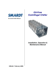
MULTISTACK
MS80T
Turbostack Modules
OPERATION & MAINTENANCE
Multistack
365 South Oak
PO Box 854
West Salem, WI 54669
608-786-3400 phone 608-786-3450 fax
www.Multistack.com
Table of Contents
1.0
Chiller Identification…………………………………………..……………….3
1.1
Model Number …………………………………..……………………...3
1.2
Serial Number………………………………………………………….3
2.0
Theory of Operation……………………………………………………………4
3.0
Daily Log Sheet……………………………………………………………...…4
4.0
Pressure Readings…………………………………………………………..….4
5.0
Strainer Cleaning…………………………………………………………..…..5
6.0
Oil Level……………………………………………………………….………6
7.0
Refrigerant Charge / Evacuation…………………………………….…………7
8.0
.
9.0
Filter Driers………………………………………………………….…………7
10.0
Pressure Relief Valve……………………………………………….….………7
11.0
Annual Maintenance……………………………………………………………8
12.0
Compressors…………………………………………………………….……...8
13.0
Heat Exchangers…………………………………………………….……….…9
14.0
Troubleshooting Water Cooled……………………………… ……..………….9
15.0
Daily Log Sheet………………………………………………………………..10
Superheat / Subcooling……………………………………………..………….7
1.0
Chiller Identification
The module data plate which contain the model and serial number for all Turbostack
modules is located on the electrical box door of each module
.
1.1
Model Number
MS80T1H2W-V
MS
80
T
1
H
2
W
-V
MS = Multistack
80 = tons
T = Turbocor Centrifugal
1 = single cond & evap std. efficiency
H = 460V
2 = wired as multiple module
W = water cooled
V = variation (* if noted)
1.2
Serial Number Identification
JD-06-25
J = --0- (decade built)
I = 1990’s
J= 2000’s
D = ---4 (year built)
A= ’01
B= ’02
………………………….
06 = June (month built)
01 = Jan.
02 = Feb.
………………………….
25 = 25th module built
01 = 1st
02 = 2nd
…………………………..
2.0 Theory of Operation
The Multistack Turbostack chiller provides chilled water to an external load based
off of the leaving chilled water temperature sensed in the Multistack master
control. When the Leaving Chilled Water sensor sends the signal to the master
control that cooling is needed, compressors will begin to start and produce chilled
water. The point at which the LCHW temperature calls for compressors to start is
determined by the Loset-point setting in the system variables menu of the master
control.
When the LCHW sensor senses that the chilled water temperature has dropped
below the set-point, compressors will begin to cycle off.
3.0 Daily Log Sheet
On the back page of this manual is a chiller information log sheet. The log sheet
can be used daily, weekly or as desired to record operation characteristics of the
chiller. The information recorded on the log sheet can also be very helpful for
diagnosing potential problems in the system.
4.0 Pressure Readings / Cut- Outs
The operating suction and discharge pressures in the system are directly related to
water flow, condenser temperatures, chilled water set-point, and the cleanliness of
the system.
The Turbostack modules use R-134a refrigerant. With standard conditions of 55º
ECHW, 45º LCHW, 85º ECW, 95º LCW, the suction pressure should be
approximately 32 psig with a 135 psig discharge pressure.
All Turbostack modules have multiple high pressure cut out safety devices. The
HP cut out is 200 psig through the PCO2 master control internal controls. The
compressor itself has a cut out set at 232 psig. A 2nd back up switch set at 240
psig is also on each module. This switch has a manual reset button on it.
Each Turbostack module also has multiple low pressure safety devices. The LP
cut out is 20 psig through the compressors internal controls. A back up switch set
at 15 psig is also on each module. This switch has a manual reset button on it.
If circuits are faulting on HP the first action to be taken should be checking the
condenser water inlet filter cartridge for debris. See filter strainer cleaning
procedure in section 5.0.
A LP fault is an indication of low refrigerant charge in the system. If a circuit is
going out on a LP fault check the static pressure of the system while the circuit is
in the off mode. If pressures are low check the circuit for possible leaks. The
circuit can be pressurized to 15 psig with refrigerant and topped to 160 psig with
dry Nitrogen.
5.0 Strainer Cleaning
All Turbostack modules have a 30 mesh filter cartridge in the condenser and
evaporator inlet header. The purpose for the filter cartridge is to keep debris from
entering the heat exchanger. An external “Y” or basket type system strainer
should also be installed as a pre-filter to the Turbostack strainers.
There is no set time for cleaning the filter cartridges. The frequency of this
process is dependant on the water quality in the condenser and / or evaporator
loop.
Normally, debris in a water loop is going to take the path of least resistance and
build up on the last modules to receive water. Multistack modules come with an
auto blow down (the DDRS-210A) installed on the condenser side of the last
module to receive water flow. The DDRS-210A is controlled by a timer in the
master control, it opens once a day to remove debris from the loop. The DDRS210A does not eliminate the need to pull the filters for cleaning. It is however
meant to decrease the frequency.
The effect of debris being built up in the condenser water inlet filter cartridge will
be nuisance HP (high pressure) faults. By checking the pressure differential
between the inlet and outlet of the condensers, an indication can be determined if
the filters are contaminated. Refer to the Product Data Catalog for correct
pressure drop of your model. To keep HP faults from repeating, the filters will
need to be pulled. If HP faults still occur after cleaning the filter cartridges the
condenser pump should be checked for proper flow. If flow is not a problem the
heat exchangers may need to be cleaned. Refer to section 11.0 on Heat
Exchanger Cleaning.
Following is the procedure for removing and cleaning the filter cartridges on the
condenser side.
1. Turn off the chiller, shut down the condenser pump, and close the butterfly /
gate valves to the condenser.
2. Drain the water remaining in the condensers and header pipes. You can do
this by opening the drain valve in the supplied pipe stubs or removing the end
Victaulic cap on the DDRS-210A.
3. Remove the first filter in the DDRS and remove all remaining filters in the
bottom condenser header pipes. You may need to fabricate a tool to hook
onto and pull the strainers out through the DDRS end.
4. Slowly open the top butterfly / gate valve and allow water to flow through the
condensers and onto the floor for approximately 30 seconds. This will push
out any debris that was trapped in the bottom of the heat exchanger as the
filters were removed
5. Clean the filters with hose, power washer, or wire brush as needed and reinstall. Slide filters in until you hit the filter stop ring on the first module.
Some people like to keep an extra set of strainers for quick re-installation.
These filters are available for purchase through your local Multistack
Representative.
6. Close the system by installing any Victaulic clamps previously removed.
7. Open the ¼” petcock bleed valves on the pipe stubs.
8. Re-fill the system by opening the bottom butterfly / gate valve and filling
from the bottom up. Close the ¼” petcock valves and open the top butterfly /
gate valve after the air has been bled from the system.
9. Restart the condenser pump. Bleed any remaining air in the system once the
pump has started and re-start the chiller
If circuits are faulting on Low Suction Temperature, or Low Chilled Water
Temperature the chilled water inlet filter cartridge should be checked. The
strainers are located in the top header on the CHW side so the previous
instructions on condenser strainer removal do not have to be exactly followed. If
the strainers are clean the fault is most likely being caused by a low flow
condition or to low of set-points in the master control. If these possibilities are
eliminated the evaporator heat exchangers may need cleaning.
6.0 Compressor Oil Level
The Turbostack Chiller uses an oil-less centrifugal compressor. There is no oil in
the system.
7.0 Refrigerant Charge / Evacuation
All Turbostack modules come factory charged with the recommended refrigerant
volume. Prior to charging, each circuit is evacuated to a maximum of 150
microns and held 15 minutes. The proper refrigerant charge for each module can
be found on the module data plate. The Turbostack is charged to 45 lbs. of R134a.
For proper charge on water-cooled machines the circuit should be charged until
the sight glass just clears.
8.0 Filter Driers
Turbostack modules contain very short piping runs to the major components.
Only a micro refrigerant charge (.6 of a lb. per ton) is used, and all circuits are
evacuated to 150 microns. For this reason a liquid line filter drier is not factory
installed in the unit.
When changing a major component in the system, a replaceable core liquid line
filter kit can be added to reduce contamination. The filter kit can be purchased
from Multistack through your local Multistack Representative. Installation
instructions and drawings are also available from Multistack.
9.0 Superheat / Subcooling
Turbostack modules use either a mechanical type expansion valve or an electronic
type valve controlled through the compressor.
By turning the mechanical valve adjustment clockwise superheat is increased.
To access control of the electronic expansion valve you will need the Turbocor
Monitor software program and a PC.
On MS modules, superheat is set at the factory during the run test. Superheat is
set for 10 – 12 degrees during the test run.
Subcooling is necessary in the system to prevent flash gas as the refrigerant enters
the expansion valve. Multistack condensers are sized so that subcooling of the
liquid refrigerant will take place with no separate subcooler being needed. The
general range of subcooling seen is 10- 20 degrees.
10.0 Pressure Relief Valve
MS modules do not have pressure relief valves as a standard component. If
desired or required by local code, pressure relief can be added as an option.
11.0 Maintenance
Most of the annual maintenance requirements for Turbostack Chillers involve
proper shut-down of the machine, and cleaning of the heat exchangers.
Preventative Maintenace bulletin #021594PM and Heat Exchanger
Cleaning Procedures bulletin #091594CP describe the recommended
procedures for both processes. Multistack has available the 151A Cleaning Kit to
assist with this process. Please see the 151A Cleaning Kit bulletin # 090195CK
for more details. All of these bulletins are part of the standard O&M manual
package.
11.1
Annual Maintenance Checks
1. Electrical Components
a. check all external interlocks
b. inspect compressor terminals
c. tighten all contactor, relay and circuit breaker terminals.
d. check all safety controls.
e. check and record voltages and amperages for compressors.
f. inspect relay contacts for damage or pitting
2. Refrigeration Circuits
a. analyze refrigerant with tube type moisture/acid analyzer.
b. check and record refrigerant subcooling and superheat.
c. check liquid solenoid valves (if applicable)
d. check expansion valve and sensing bulb connections.
3. Condenser and Chilled Water System
a. clean pump strainers and system strainers.
b. remove header caps and clean the CW and CHW strainers in
accordance with the Multistack™ Annual Cleaning Procedure detailed
in this manual
4. Cabinet and Related Hardware
a. dry clean electrical panels, remove debris.
d. apply protective coatings or wax if required.
6. Update Your Maintenance Log Book!
7. The Capacitors on the compressor’s have a lifetime of 5-10 years. Turbocor
recommends replacing these in that time frame.
12.0 Compressors
With any chiller system there is always the chance of a compressor failure. In the
event of a failure, proper steps should be taken to determine the cause of the
failure.
A motor burn due to a fault in the motor insulation is quite rare. Most burnouts
are actually caused by a mechanical condition or lubrication problems. In the
event of a burnout, proper clean up procedures should be followed.
1. Check all electrical components of the circuit (contactors, fuses, wires,
etc.)
2. If necessary do a system clean up. Nu-Calgon RX-11 flush, or Sporlan
System Cleaner work well.
3. Install a liquid line filter drier with burnout core. See section 7 on
filter driers.
4. Evacuate the system to a minimum of 500 microns and hold for 20
minutes.
5. Charge the circuit with virgin refrigerant. Charge with liquid into the
discharge side. See refrigerant charge on nameplate data of unit.
6. Run the system 2-3 weeks with burnout filter core. Replace with
standard core drier.
13.0 Heat Exchangers
Multistack uses brazed plate stainless steel heat exchangers for all condensers and
evaporators.
Without proper water treatment or due to abuse, heat exchangers, especially
condensers can corrode over time and eventually develop an internal leak. In
such an event it would become necessary to replace the heat exchanger.
Following are the step’s for field replacement of a failed condenser or evaporator
heat exchanger.
1. If the refrigerant has not been lost on the failed circuit, you should first
do a standard refrigerant recovery.
2. Begin by isolating the chiller and draining water from the side to be
worked on.
3. Remove the 8” water header pipes by unbolting the victaulic couplings
4. Using a saws all you can now cut the refrigerant piping to remove the
heat exchanger. Cut on the bottom side of the elbow and sweat off
remaining portion of old elbow.
5. Remove the red support brace that holds both heat exchangers in place.
Once this is removed you can remove the defective exchanger.
6. Set the new heat exchanger in place and re-install the support brace.
7. Fit the couplings and refrigerant piping into the heat exchanger. You
may need to loosen the bolts at the compressor at this time.
8. Braze in the new exchanger while purging with a low pressure of
nitrogen.
9. After brazing leak check and evacuate to a maximum of 500 microns.
Charge the circuit according to the name plate charge.
If the heat exchanger failure has caused water to enter into the refrigerant side, the
compressor and opposite side heat exchanger should also be checked for possible
contamination. If water has entered into the compressor it is recommended the
compressor be replaced, as removing all the moisture from it is very difficult.
Replacement of the other contaminated heat exchanger, the expansion valve, and
installation of a liquid line drier with a water core cartridge is also recommended.
Evacuate the circuit to a maximum of 500 microns and let stand for 20 minutes.
Charge the circuit and run 2-3 weeks with the high water core cartridge and then
replace with a standard core.
14.0 Troubleshooting Turbostack Module
Turbostack modules use the Carel PCO2 master control. The user manual for the
Turbostack PCO2 controller is located in section 6 of the O&M package. The
user manual details the different status screens and explanations of system or
module faults.
The following guide is for troubleshooting Turbostack modules and the PC02.
FAULT
SOLUTION
No Display on Master Module
Check main disconnect for power
Check circuit breakers in module
Check transformer in modules
Check for 24V at J1 on board
EX 1,2, Interlock
Check appropriate interlock component
Check jumpers on TS2 in master module
EX 4 Interlock
Check for proper rotation, phasing
Check PPM device
Waiting For Chilled Water Flow
Check CHW pump
Check flow switch operation
Check filter strainers
Check TS2 inputs #3 - #7
Low Chilled Water Temp
Check LCHW sensor
Check setpoints in system variables
Check for flow restriction
No Demand
Check LCHW sensor
Check setpoints in system variables
Check sensor location
100% Demand all the time
Check LCHW sensor
Check setpoints in system variables
100% Demand, chiller won’t load
Turn chiller on
Check sensors
Check load limit setting in system variables
Excessive Cycling
Check LCHW sensor location
High Discharge Pressure (HP)
Check condenser water flow
Check and clean system strainer
Check and clean filter cartridges in modules
Check pressure switch operation
Low Suction Pressure (LP)
Check refrigerant charge / leaks
Check expansion valve
Low Suction Temperature
Check suction sensor
Check setpoints in system variables
Check for flow restriction
Communication Error
Check settings in system variables
Check cables at J11 comm ports
Check dip switch settings
Circuit Fault
Check components in control circuit
Check wire crimps in control circuit
P Lan Error
Check P-Lan cabling and connections
Check for possible airwave interference
lll MULTISTACK
CHILLER
DAILY LOG SHEET
DATE
Status
Suct. Press
Head Press
Suct. Temp
LoChw Temp
Fault (if any)
Ent. Chw
Lvg. Chw
Ent CW
Lvg. CW
Demand
Capacity
Upset
Loset
VSP
Load Limit
Tdiff
Index
Comp #1
Comp #2
Comp #3
Comp #4
Comp #5
Comp #6
Comp #7
Comp #8
Comp #9
Comp #10
Comp # 11
Comp #12
System
System
COMMENTS: CHW P Drop
.
CW P Drop
.