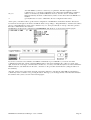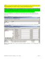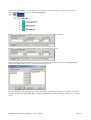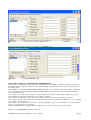
1
TRAXiT32 – Communications Manager
USER’S MANUAL
Revision 2.5
AXESS TMC srl - Via della Filanda, 22
40133 Bologna - Italia
Tel: +39 051 3519311
Fax: +39 051 3519399
mailto:[email protected]
http://www.axesstmc.com
INTRODUCTION
• TRAXiT32 is a programme suitable for 32 bit Windows systems created for solving the problem of configuration
and data upload/download for TMC terminals equipped with filesystem.
TRAXiT32 is not suitable for operating under Windows 3.XX.
• TRAXiT32 is able to manage exclusively plants of terminals used normally in OFFLINE mode, i.e. the
terminals are programmed for working in a stand-alone way, recording data in their own memory.
• TRAXiT32 doesn’t include the management of Access Control tables, although it can upload on the
terminals the tables created by means of another program.
• TRAXiT32 uses BDE (Borland Database Engine) as DBMS; the BDE system is included in TRAXiT32 installation
files.
GENERAL CHARACTERISTICS
TRAXiT32 is a communication program useful for configuration and data upload/download of TMC terminals with
offline capabilities. TRAXiT32 can manage either Time and Attendance or Production transactions coming from the
terminals; its default working mode is as follows:
1) Time and attendance transactions recorded without seconds (for compatibility with EnTRAX)and without causal
codes (default for all the terminals).
2) The data produced by PROC_? user-defined-transactions loaded into PROX and TRAX/2P terminals is recorded in
a single file PFXymmdd, where each record has a prefix of one character representing the procedure (A for
PROC_A, B for PROC_B and so on) and each field is identified by a small capitals letter (“a”, “b”, etc.). This
mode of storing data can be set on each terminal by means of par.27-Storage set to 4; the same result can be
achieved inserting the command @S4 as one of the first lines of the user-defined transaction script (after the
title).
The EnTRAX terminal is not able to manage user-defined transactions.
3) File transfer from terminal to PC with checksum control enabled (par.17=1 for PROX and TRAX+P, par.50=1 for
EnTRAX).
PREREQUISITES (PC)
Operating System: Microsoft Windows 32 bit.
Hardware: RAM 128 MB (suggested 256 MB), HD 250 MB.
Display: set to 800x600 pixels or more, 65K colors and (very important) SMALL CHARACTERS.
Network: every network system compatible with the version of Windows installed. Ethernet and TCP-IP transport
protocol required when plants include one or more EtherBoxes. In this case, you should check the directory SYSTEM
of WINDOWS for the presence of WINSOCK.DLL system extension, otherwise please contact the Microsoft company
in order to obtain the version of WINSOCK.DLL file suitable for the Operating System release installed onto your
computer.
NOTE: when TRAXiT32 manages plants connected via the serial ports of the P.C. by means of MicroLD or PSLD/3
adaptors, please check that the TRANSMISSION and RECEPTION FIFO queues of the UARTs are set to minimum
values in the serial ports setup. For example, for the COM1 port, execute the following operations:
Enter the “Control panel:System:Peripheral management:COM and LPT ports:Communication port (COM1):Port
setup” and clic on the “Advanced” button then set to the leftmost position the cursor of both “Reception buffer” and
“Transmission buffer”. The checkbox should be enabled.
IMPORTANT: for the PCs equipped with O.S. Windows NT, Windows 2000 and Windows XP, after the setting of
FIFO queues as specified above, it is necessary the reboot the PC, also if the system doesn’t explicitly request this
operation.
TRAXiT32 Communications Manager – User’s manual
Page 1
THE INSTALLATION FILES
The installation of TRAXiT32 and its database manager (BDE) can be carried out starting from diskettes or CD-ROM;
if you receive the software by e-mail, please copy the following files into a temporary directory, then launch the
"TRAXiT32-Setup.exe" program and follow the installation instructions.
The following files contain the documentation:
TRAXiT32 Manual-ITA-<release>.PDF contains the TRAXiT32 documentation (Italian).
TRAXiT32 Manual-ENG-<release>.PDF contains the TRAXiT32 documentation (English).
INSTALLATION REQUIREMENTS
Installation of TRAXiT32 on Windows NT or Windows 2000 or Windows 2003 systems requires that the user be
logged in as Administrator.
SINGLE-USER INSTALLATION
Normally TRAXiT32 is installed onto a PC connected to a terminal’s plant through the PC’s serial ports or through the
Ethernet network in the case of EtherBoxes being used.
In any case, it is necessary the BDE installed and configured onto the PC which will run TRAXiT32, also when data (or
TRAXiT32 itself) will reside onto a file-server.
1) Login as ADMINISTRATOR and install TRAXiT32 on a local hard-disk unit or on a network one. Before starting
a network installation, it is necessary to associate a logic unit (X:, W:, etc.) to the network unit: in “Windows
Explorer”, select the menu choice “Utilities:Connect network unit” and activate the “Connect at startup” checkbox,
as shown in the following figure:
TRAXiT32 Communications Manager – User’s manual
Page 2
2) Configure the BDE of the PC: in the control panel, double clic on the element “BDE Administrator”.
a) In the “Configuration” tab, select the item “PARADOX” on the left and modify the field “NET DIR” on the
right, SPECIFYIONG ALWAYS A LOCAL PATH WHERE EACH USER HAS ALL THE ACCESS
RIGHTS to the file PDOXUSRS.NET. This consideration is valid also if TRAXiT will be executed as a
service of Windows, see the corresponding paragraph in this manual.
3) Give all the users full access rights to the folder “C:\Program files\Common Files\Borland Shared\BDE”.
4) Launch TRAXiT32 for the first time as local ADMINISTRATOR; it is not sufficient to be a domain administrator.
The next times TRAXiT32 could be launched as any kind of user.
NOTE FOR WINDOWS 2003 SERVER SYSTEMS: in order to allow TRAXiT32 being executed by any user, when
the installation finishes the Administrator should go in the folder where TRAXiT32.EXE has been installed, right-clic
on the file TRAXiT32.EXE and modify the properties of the programme as shown in the following figure:
MULTI-USER INSTALLATION
A multi-user installation of TRAXiT32 makes sense only in an Ethernet network of PCs using TCP-IP transport
protocol, with terminals connected to EtherBoxes. In this case, normally TRAXiT32 will run on more than one PC (but
not concurrently) and data will reside on a file-server, along with TRAXiT32 application programme.
1) On the first P.C.: login as ADMINISTRATOR and install TRAXiT32 on the desired network disk unit, e.g. the
unit assigned to the logical drive “W:”, path “W:\TRAXIT32”; this will install also the BDE (Borland Database
Engine).
2) Launch TRAXiT32 as ADMINISTRATOR and register it (see chapter below).
3) Exit from TRAXiT32.
TRAXiT32 Communications Manager – User’s manual
Page 3
1) On all the remaining P.C.: login as ADMINISTRATOR and install TRAXiT32 on a local disk unit (e.g.
C:\TRAXiT32 or D:\TRAXiT32); this will install also the BDE (Borland Database Engine). Launch TRAXiT32
and execute the registration of the program (see chapter below). Uninstall TRAXiT32 (see chapter below): this
operation doesn’t remove the BDE, nor the user’s registration, nor the DLL necessary for using TRAXiT32 in
network. Create a shortcut to file TRAXiT32.EXE installed onto the network drive and put it (for example) onto
the desktop of each P.C.
2) Configure BDE of every PC which will run TRAXiT32: from the control panel, double-clic on the “BDE
Administrator” element.
a) In the “Configuration” tab, select the item “PARADOX” on the left and modify the field “NET DIR” on the
right as shown in the following figure:
b) Press the blue button
in order to confirm the changes, then exit
3) Give all the users full access rights to the folder “C:\Program files\Common Files\Borland Shared\BDE”.
Give all the users full access rights to the file “<path>\PDOXUSRS.NET”.
5) By means of the shortcut, launch TRAXiT32 for the first time as ADMINISTRATOR. The next times TRAXiT32
could be launched as any kind of user.
NOTE FOR WINDOWS 2003 SERVER SYSTEMS: in order to allow TRAXiT32 being executed by any user, when
the installation finishes the Administrator should go in the folder where TRAXiT32.EXE has been installed, right-clic
on the file TRAXiT32.EXE and modify the properties of the programme as shown in the figure of chapter “SINGLEUSER INSTALLATION”.
NOTE FOR WINDOWS VISTA SYSTEMS: in order to execute TRAXiT32 properly under Microsoft Vista
Operating System, it is necessary to enter the Control Panel and DEACTIVATE the "User Account Control" option.
USER’S REGISTRATION
When launched for the first time, TRAXiT32 asks the user for selecting the language in which messages will be shown
(currently available English, Italian, Spanish and Catalan), then shows a dialog window like the following:
TRAXiT32 Communications Manager – User’s manual
Page 4
It is possible to select between two different types of registrations:
• Demonstrative registration: clicking the corresponding button and then “OK”, the program is active for 30 days,
and it is possible to completely evaluate its funcionalities, including the communications with the terminals.
• Definitive registration: you should insert at least eleven characters in the “Company’s name”, “Address” and
“VAT number” fields, and you should communicate them EXACTLY AS THEY HAVE BEEN WRITTEN
(including spaces, dots, commas, etc.) to the software supplier company – AXESS TMC Srl - by fax (+39 051
3519399), phone (+39 051 3519311) or E- mail (mailto:[email protected]). You will receive an “Activation key”
made by a 24-characters string (in the range 0..9, A..F), which should be inserted in the field “Activation key”. If it
is impossible for you to complete the definitive registration, you can make a demonstrative registration, and only
successively register the program by means of the menu item “Help:Registration”.
When the field “Activation key” contains a valid 24-characters string, clicking on the “OK” button the program starts in
the selected mode (Demonstrative or Definitive), otherwise a warning message is shown
UNINSTALLING TRAXiT32
In order to uninstall TRAXiT32 it is sufficient to launch the program “Uninstall TRAXiT32” located in the group of
programs created when “TRAXiT32” was installed.
If necessary, you can also uninstall the BDE by means of Window’s control panel, activating the item “Add/remove
programs”, selctin the item “BDE” and finally clicking the “Add/remove” button.
HOW TO PERSONALIZE TRAXiT32
The images contained in the files MAINLOGO.BMP and MINILOGO.BMP are shown respectively during program’s
startup and in the right of the splash screen. The image contained in the file USERLOGO.BMP is shown in the window
containing the information about user’s registration. If you want, you can replace these files with two bitmap files
containing the logo of your company; when executing these operations, TRAXiT32 should be inactive.
TRAXiT32 Communications Manager – User’s manual
Page 5
HOW TO CHANGE THE MESSAGES OF TRAXiT32
ATTENTION: If you are intentioned to modify the messages, or you want to translate the messages
in a language not yet present, please contact TMC which will communicate to you the procedure to
follow in order to have your messages included in the next releases of the program. Otherwise, when
you will install an update of the program, you will loose the work done until that moment.
In order to change the messages shown in TRAXiT32 you only need to lanch the “Language ” program located in the
group of programs created when “TRAXiT32” was installed.
The program allows to see the messages in both “List” or “Detail” mode; this last mode allows to display at the same
time the same message in all the available languages.
Entering a string in the field in the upper left of the window, the cursor will be positioned on the line which begins with
that string: the search is carried on the messages in “Native” language.
TRAXiT32 Communications Manager – User’s manual
Page 6
THE MAIN SCREEN OF TRAXiT32
The programme TRAXiT32 allows to visually create and maintain plants made up of different devices such adaptors,
terminals, etc.
By means of “Plant” buttons it is possible to operate the main functions on plants:
• Create new plant
• Open plant
• Save plant
• Remove plant
The same functions are available in the “File” menu, in addition to the “Save as…” menu choice.
By means of “Edit” buttons it is possible to operate the main editing functions on the selected element of the plant
currently displayed:
• Cut
• Copy
• Paste
• Delete
• Expand/Collapse
• Move up one element
• Move down one element
The same functions are available in the menu shown when you right-clic the mouse on one element, in addition to the
“Expand all” and “Properties” menu choices.
The first four functions are available in the “Edit” menu and via the accelerator keys:
Cut
CTRL-X
Copy CTRL-C
Paste CTRL-V
Delete DEL
SELECTING THE LANGUAGE OF THE MESSAGES
The button “Options” of the main screen allows the selection of the language of messages shown in the programme.
Currently the Italian, English, Spanish and Catalan languages are supported.
TRAXiT32 Communications Manager – User’s manual
Page 7
THE TWO OPERATING MODES OF TRAXiT32 – OPERATOR AND ADMINISTRATOR
TRAXiT32 starts in “OPERATOR mode” which only allows to:
1) Send configuration parameters to the terminals, along with date/time and configuration files.
2) Edit the ALARMTB files, either generic or associated to the “Upload profile” of the selected terminal.
3) Download data from the terminals, which will be automatically exported (i.e. converted with a predefined format)
in the TXT file specified in the “Download profile” associated to the terminal.
Selecting the “File:Password” menu item, the following dialog box is shown:
After first installation, TRAXiT32 is set with a blank password; you can enter your own password by filling the “New
password” and “Confirm password” fields and pressing the “Confirm” button.
When a valid password is supplied, TRAXiT32 enters in “ADMINISTRATOR mode”, which allows to:
1) Create, modify and delete plants.
2) Modify all the property sheets of all the items of the plant.
3) Directly manage the configuration and the file system of the terminals.
4) Manage the backup files on the PC, containing data downloaded from terminals (and probably deleted from their
memory).
CREATING A NEW PLANT – THE DRAG AND DROP
TRAXiT32 supports different communication interfaces…
…and Time and Attendance, data collection terminals.
You can define a configuration by clicking the mouse on the element you want to add and dragging it to the position
where you want it in the plant.
The LIMITED versions of TRAXiT32 makes it possible to pick-up only one type of terminal, to be connected
directly to the serial port of the P.C.
TRAXiT32 Communications Manager – User’s manual
Page 8
You can’t make mistakes as TRAXiT32 prevents you from making connections which are not possible. In the following
plant, you can’t connect a TRAX/2P directly to the PC’s COM port; you should connect TRAX/2P to the PC by means
of a Current Loop adapter.
COPYING, CUTTING, PASTING AND MOVING DEVICES
Once you have defined and configured a device (e.g. a terminal of a multipoint installation of 25 terminals), you can
copy the device (CRTL-C) and paste it (CTRL-V); you can also cut a device (CTRL-X) or delete it (DEL). All these
editing functionalities are accessible by means of the right button of the mouse.
THE PROPERTY SHEETS OF PLANT’S DEVICES
All the devices involved in the definition of a plant have at least one “property sheet” containing information about the
device; when in “ADMINISTRATOR mode”, right-clic on a device for opening its property sheet(s). For example, here
follows the “General” tab of a PROX’s property sheet:
WARNING: Once you have assigned different names to the terminals (field “Name” of the
“General” property sheet), if you have already downloaded data, DON’T CHANGE THE NAME OF
THE TERMINALS, OTHERWISE ALL DATA PRESENT IN THE TERMINAL WILL BE
DOWNLOADED AGAIN.
TRAXiT32 Communications Manager – User’s manual
Page 9
PREPARING THE PLANT AND THE DEVICES
In the next paragraphs are shown all the plant configurations managed by TRAXiT32. Will be given the basic
information useful for the “quick connection” between PC and terminals. For more details about terminal configuration
and connections, please refer to each device’s USER MANUAL.
The configuration of the terminals and the definition of download politics will be described later.
WARNING: BEFORE YOU BEGIN TO DOWNLOAD DATA WITH TRAXiT32, DELETE
COMPLETELY THE CONTENTS OF THE MEMORY OF THE TERMINALS by means of
commands “%%2” and “%%3”, check date and time of the PC, then setup the terminals.
4-KEYS RS232 EnTRAX WITH DIRECT CONNECTION
1) Connect the RS232 cable from the serial port of EnTRAX to the RS232 port of the P.C. following the instructions
written in the short form contained in the box of EnTRAX, where are described the connections between the
EnTRAX’s gray cable and the T-BOX, and between the T-BOX and the PC.
2) If the terminal is brand new, the preparing operations are finished as the communication port of EnTRAX is set by
default to 9600N81 with XON/XOFF handshake.
If you anyway know the current setting of the communication port of the terminal, then set TRAXiT32 with the
same configuration, in the tab “Configuration:Ports” of the terminal. Otherwise, if you don’t know how is currently
configured the terminal’s communication port, you can try to execute a complete “RESET” of the terminal itself,
following the proper procedure described in the user’s manual.
WARNING: the “RESET” procedure, id addition to setting the EnTRAX’s configuration parameters to the
default (with TTY communications at 9600N81 and XON/XOFF handshake), causes the complete deletion of
the memory contents.
PROX WITH DIRECT RS232 CONNECTION
1) Connect the RS232 cable coming from PROX’s serial port to the RS232 port of the PC. It is sufficient a three-wires
cable: TX, RX and GND.
2) Connect together the RTS and CTS screw connectors of the PROX’s selected port by means of a short wire.
3) Set up PROX’s communication parameters (baudrate, ecc.) related to the selected communication port. The
suggested configuration for PROX’s COM1 is 9600N81 and XON/XOFF (default). COM2 has default parameters
2400N81 and XON/XOFF. In case of doubt, execute a complete “RESET” of the terminal by pressing the RESET
button for more than 3 seconds; this operation will bring all the PROX’s configuration parameters to their default
values. Of course, if you change the communication speed of PROX’s COM port, the same speed should be
selected for PC’s COM port.
4) Execute a “RESTART” of the terminal, either by pressing for a short while the “RESET” button located into the
terminal or switching it OFF and ON again (pressing the [<->] key for more than 3 seconds and then the “|” key).
TRAXiT32 Communications Manager – User’s manual
Page 10
PROX WITH DIRECT RS232 CONNECTION AND SLAVE TERMINALS
This kind of connection is very similar to the previous one: please follow the points 1..4.
The slave terminals (PROX#2, TRAX#1, EnTRAX #1 in the previous figure) are connected to the NET92 screw
connectors of Master PROX#1 by means of a RS485 line: please refer to PROX’s user manual.
Furthermore, it is necessary to set NET92 addresses of slave terminals, one different from the other; the same setting
must be done in the “NET92 ID” field of “General” tab of each terminal. Each PROX can be Master of up to 31
terminals, with NET92 addresses in the range 1..31. In PROX and TRAX/2P the NET92 address is stored into par.19Address, while in EnTRAX it corresponds to par.01-Address.
NOTE: while the NET92 address of PROX and TRAX/2P terminals can be set directly by the keyboard, for 4-Keys
EnTRAX the procedure is a little bit more complex.
Setting NET92 address in EnTRAX – Master/Slave:
1) Deactivate ALL the slave terminals from the NET92 port of Master PROX (i.e. shut them OFF or disconnect them
from the NET92 network).
2) Select the tab “Property:Advanced” of the Master PROX and clic on the “Connect” button.
3) When connected, put the cursor into the field on the bottom of the window and send the following commands:
CFG 18 16
Sets the communication mode of Master PROX (CFG{space}18{space}16)
%%
Executes a “restart” of Master PROX
4) Activate ONLY one EnTRAX terminal, for example the one which will be given the NET92 address ‘1’. Set the
“NET92 ID” field of “General” tab to ‘1’ and the “Speed” combobox in tab “Ports:NET92” to 57600.
5) Send the following commands and ignore the message “No reply from terminal”:
>00CFG 01 1
Sets the NET92 Address of EnTRAX ‘1’ (>00CFG{space}01{ space }1)
>00%%
Executes a “restart” of EnTRAX
6) Deactivate the previous EnTRAX and activate the next, for example the one which will be given the NET92
address ‘2’. Set the “NET92 ID” field of “General” tab to ‘2’ and the “Speed” combobox in tab “Ports:NET92” to
57600.
7) Send the following commands and ignore the message “No reply from terminal”:
>00CFG 01 2
Sets the NET92 Address of EnTRAX ‘2’ (>00CFG{space}01{ space }2)
>00%%
Executes a “restart” of EnTRAX
Repeat the steps 6) and 7) for all the EnTRAX terminals, giving them NET92 addresses in the range ‘1’..’31’.
8) Send the following commands:
CFG 18 0
Sets the communication mode of Master PROX (CFG{space}18{space}0)
%%
Executes a “restart” of Master PROX
9) Clic on the “Disconnect” button.
The following figure illustrates an example of the described operations :
TRAXiT32 Communications Manager – User’s manual
Page 11
The following figure shows a variation of the previous plant, where PROX#1 (the master) is connected to the PC’s
serial port by means of a Current Loop interface;in this case you MUST use the PROX’s COM2 port, configure the
jumpers on the I/O board of PROX for “Current Loop” and set the baudrate of COM2 to a maximum of 4800 Baud. The
Current Loop interface greatly enhances the immunity of PC from electrical noise coming from the network of
terminals.
PROX MASTER OF MAX TERMINALS
This is a typical installation for Access Control management, where a Master PROX manages up to 31 slave MAX
terminals.
1) Connect PROX to the PC, using PROX’s COM1 or COM2 port. It is sufficient a three-wires cable: TX, RX and
GND.
TRAXiT32 Communications Manager – User’s manual
Page 12
2) Connect the NET92 network made with all the slave MAXes to the Master PROX#1 NET92 screw connectors.
3) Set the NET92 addresses of slave terminals, one different from the other. Each PROX can be Master of up to 31
terminals, with NET92 addresses in the range 1..31. The NET92 address of MAX is set by means of a bank of
microswitches on the logic board.
4) Set up the “Access Control” tab of the Master PROX and, if necessary, load the AXCARDS, AXPOOLS,
AXTIMET and AXGATES files onto the PROX.
PROX or EnTRAX CONNECTED VIA MODEM
PROX:
1) Connect the RS232 cable coming from PROX’s serial port to the RS232 port of the “answering” modem (e.g.
“Modem#2”).
2) If necessary, connect together the PROX’s RTS and CTS screw connectors with a short wire.
3) Set up terminal’s communication parameters (baudrate, ecc.) corresponding to the used COM port.
4) Execute a “restart” of the terminal, either by pressing for a short while the “RESET” button located into the
terminal or switching it OFF and ON again (pressing the [<->] key for more than 3 seconds and then pressing the
power-on “|” key).
5) Open the property sheet of each “called” modem, set the modem’s name (optional) and the corresponding phone
number:
6) Power on the modem, enter the “Administrator mode” on the terminal, select the “Modem setup” menu item and
execute the following operations:
a) Select the appropriate Modem port (1 or 2, depending from the PROX’s COM port connected to the
modem).
b) Select the number of rings to wait for before answering to the incoming call (1 or more).
c) Select the handshake type: 0 for XON/XOFF (software handshake) with three wires connection
(recommended) or 1 for RTS/CTS (hardware handshake) with five wires.
After you have entered the “Handshake” field, the terminal sends the appropriate configuration commands to the
modem and stores them into the modem’s non-volatile memory; during this operation, the “Receive data “ LED
of the modem should blink.
7) Open the property sheet of the “calling” modem (the one connected to the PC’s COM port), set the modem’s name
(optional) and fill the other fields:
TRAXiT32 Communications Manager – User’s manual
Page 13
a) The “COM” combobox sets to which PC’s COM port is connected the calling modem.
b) The “Tone/Default” radiobuttons set the dial mode of telephone number: "Default" uses the modem's
default dialing method and is suitable for connecting ISDN modems.
c) The “Extern line” field sets the “Prefix” necessary for gaining access to external telephone line (e.g. “,,0,”
or “,,9,”).
d) The “Init string ” field sets the initialization commands which TRAXiT32 will send to the calling modem
before dialling a phone number.
e) The “Connection delay” field sets the number of seconds to wait before going in timeout if the called
modem doesn’t respond.
EnTRAX:
The configuration of calling modem is the same of that described for PROX; the answering modem should be already
configured before connecting it to EnTRAX (the terminal doesn’t have a “Modem setup” menu choice”.
In this case you can configure the modem by connecting it to a PC equipped with a serial terminal emulation
programme. The configuration should be stored in the modem's own non-volatile memory (usually by means of a
command such as AT&W) so that the modem will automatically configure itself each it is switched on. For the exact
syntax of each command consult the manual supplied with the modem, or seek advice from the manufacturer /
importer.
Here follows a description of the manual configuration in "semi-dumb" mode of "answering" modem.
1) Connect the modem to a computer with a TTY terminal emulation programme which is configured for the same
communication parameters which will be set on the terminal (e.g. 9600 baud, parity N, 8 bit word length and 1 bit
stop), with local echo disabled.
2) Switch on the modem.
3) Make sure that the AA (AutoAnswer) LED lights up, otherwise send the command ATS0=2 {Enter} (sets the
automatic answer after two rings).
4) Type the following command:
ATE0Q1 {Enter}
5) Consult the modem's manual and type the command which forces the communication speed onto the serial
line (the one which is currently connected to the computer but will be then connected to the terminal)
ALWAYS AT 9600 BAUD (or another speed, in any case the same which will be configured for the serial
port of the terminal).
6) Send the command which will store all the settings into the modem's own non-volatile memory:
AT&W {Enter}
NOTES:
On the answering modem, don't set a number of rings greater than 2 or 3 (ATS0=2 or ATS0=3),
otherwise TRAXiT32 will go in "timeout" during the calling process.
If the modem has a 25 pins connector, connect together the pins 4 and 5. Connect together the pins 6
and 20.
TRAXiT32 Communications Manager – User’s manual
Page 14
If the modem has a 9 pins connector, connect together the pins 4 and 6. Connect together the pins 7
and 8.
In the following figure is shown an example of of connection between EnTRAX and Modem, using the T-BOX and
cable supplied with the terminal. Please pay attention to the inversion of TXD and RXD connections into the T-BOX
respect to a EnTRAX <-> PC connection; furthermore, there is a male-male adaptor which makes it possible to connect
the 9-pin female connector of the EnTRAX to the male connector normally available on the modem. Of course, if the
modem has a different kind of connector, you should use a suitable adaptor.
RS232 Modem
Power12Vdc
RXD
M-M
adaptor
TXD
12Vdc
0V Gnd
PROX CONNECTED VIA MODEM AND SLAVE TERMINALS
This kind of connection is very similar to the previous one: please follow the points 1)..7). The slave terminals
(PROX#2, TRAX#1 and EnTRAX#1) are connected to the Master PROX#1 NET92 screw connectors by means of a
RS485 line: please refer to PROX’s user manual.
Furthermore, it is necessary to set NET92 addresses of slave terminals, one different from the other; the same setting
must be done in the “NET92 ID” field of “General” tab of each terminal. Each PROX can be Master of up to 31
terminals, with NET92 addresses in the range 1..31. In PROX and TRAX/2P the NET92 address is stored into par.19Address, while in EnTRAX it corresponds to par.01-Address.
NOTE: while the NET92 address of PROX and TRAX/2P terminals can be set directly by the keyboard, for 4-Keys
EnTRAX the procedure is a little bit more complex. For more details, please refer to the procedure described in
Setting_NET92_address_in_EnTRAX_Mast_Sl
TRAX/2P WITH DIRECT CONNECTION
TRAXiT32 Communications Manager – User’s manual
Page 15
TRAX/2P has a communication port with electrical interface “Current Loop”: thus it is always necessary to convert the
RS232 signal levels of the connected device (PC, Modem, printer, etc.) to “Current Loop” levels by means of TMC
#984 CL-232 adaptor. This device can communicate at a max speed of 4800 Baud.
1) Connect the Current Loop’s RS232 D-type connector to the RS232 port of the PC; if necessary, use a 9pin female25pin male pin-to-pin adaptor. Make sure that pin 4 (RTS) or pin 20 (DTR) of the 25-pin connector of Current
Loop interface is at “high” electric level (12 VDC - will be used as ‘power supply’ of the RS232 side of adaptor).
2) Set up terminal’s communication parameters (baudrate, etc.) for the COM port. The suggested configuration is
4800N81, terminators of reception/transmission "CR" (not "CR LF") and no handshake.
3) Execute a “restart” of the terminal by pressing the [<->] key for more than 3 seconds.
TRAX+P CONNECTED VIA MODEM
1) Open the casing of the Current Loop interface, find the two jumpers on the board and set them as shown in the
following figure, then close the casing:
JP1
CL-232
2) Connect the Current Loop’s RS232 D-type connector to the RS232 port of the “called” modem by means of a
male/male pin-to-pin adaptor suitable for the type of connector mounted on the modem. Check that the “called”
modem is powered and switched on.
3) Make sure that pin 4 (RTS) or pin 20 (DTR) of the 25-pin connector of Current Loop interface is at “high” electric
level (12 VDC - will be used as ‘power supply’ of the RS232 side of adaptor).
4) Set up terminal’s communication parameters (baudrate, etc.) for the COM port. The suggested configuration is
4800N81, terminators of reception/transmission "CR" (not "CR LF") and no handshake.
5) Execute a warm boot of the terminal by pressing the [<->] key for more than 3 seconds.
6) ANALOG MODEM: power on the answering modem, enter the configuration menu of the terminal and select the
“Modem setup” item:
a) Set to ‘1’ the number of rings to wait for before answering an incoming call.
After having entered the number of rings, the terminal sends the configuration commands to the modem; during
this operation, the “ SEND DATA” led of the modem should blink briefly and the “AUTO ANSWER” led shoul
remain on. THE BLINKING CONFIRMS THAT THE CONNECTION TERMINAL<->MODEM IS
WORKING CORRECTLY.
TRAXiT32 Communications Manager – User’s manual
Page 16
ISDN MODEM: power on the answering modem, don’t use the menu item “Modem setup" of the terminal, but
execute the steps 1..4 described before for the connection of modems to EnTRAX terminals (paragraph PROX
or EnTRAX CONNECTED VIA MODEM).
7) Open the property sheet of each “called” modem, set the modem’s name (optional) and the corresponding
telephone number:
8) Open the property sheet of the calling modem (the one connected to the PC’s COM port), set the modem’s name
(optional) and the other fields:
The “COM” combobox sets to which PC’s COM port is connected the calling modem.
a) The “Pulse/Tone” radiobuttons set the dial mode.
b) The “Extern line” field sets the “Prefix” necessary for gaining access to external telephone line (e.g. “,,0,”,
“,,9,”).
a) The “Init string ” field sets the “Initialization commands ” which will be sent to the calling modem before
dialling a phone number.
b) The “Connection delay” field sets the number of seconds to wait before going in timeout if the called
modem doesn’t respond.
TERMINALS CONNECTED VIA PLSD/3 OR PSLD/3I IN NET92 NETWORK
TRAXiT32 Communications Manager – User’s manual
Page 17
This is a typical installation of a RS485 network of TMC terminals supporting the NET92 multipoint protocol. The
PSLD has two NET92 lines, each supporting the connection of up to 31 terminals for a cable run of up to 1.2 Km. If
you need to connect more terminals (and/or obtaining a longer cable run), you can add one or more PSLD3 (not
PSLD/3I) configured as REPEATER; anyway a NET92 network can address up to 254 different terminals.
The following figure shows the “General” property sheet of a PSLD:
•
“RS232 From” combobox: selects the communication port of the PC where the PSLD is connected to
(COM1..COM4).
The following figure shows the “Communications” property sheet of a PSLD:
•
•
“Baud”, “Data bits” and “Parity” comboboxes: select the communication characteristics of the connection
between the PC and the PSLD. For PSLD Old, PSLD/2 and PSLD/3 adaptors, the “Data bits” and “Parity”
comboboxes are “grayed” because the NET92 protocol is implemented internally in the DLL, along with all its
communication characteristics; it is only possible to select the Baud.
“Model” radiobuttons: select the model of PSLD.
NOTE: When you use a PSLD/2I/3I adaptor, you should verify that the communication parameters set in the “COM1:”
section of the “Communications” tab match the communication parameters set in the adaptor. The factory presets of a
PSLD/3I match all the the working modes of TRAXiT32, including the communication baudrate set to 9600N81.
If you are going to install a PSLD/3I previously used for testing purposes (or installed in another plant), you should
restore its configuration working mode to default values, by sending the following commands, for example by means of
a communication program like Microsoft TERMINAL or Microsoft HYPERTERM. See PSLD’s user manual for
explanation of the commands and their exact syntax:
XON or CTRL-Q
sends an XON character which enables the data transmission from PSLD/3I
$…..
sets the date/time of real time clock contained in the PSLD/3I
&
clears the “automatic message”
*0
sets the CR character as terminator of the messages sent to the PC
@011
sets the XON/XOFF software handshake in both the communication directions
>B
sets the “buffered” mode
>N3
sets the communication speed of the NET92 side to 57600 baud
Then you should check the PSLD/3I microswitches, making sure that they are in the following status:
Switch 2 OFF and
TRAXiT32 Communications Manager – User’s manual
Page 18
Switch 3 ON
Switch 4 ON
Switch 5 ON
Switch 6 ON
Switch 7 ON
Switch 8 ON
9600 Baud
Parity NONE
8 bit
Hardware handshake disabled
(IMPORTANT for rel. 2.1.0.66 and older) Inclusion of time in messages sent to the PC:
disabled
Automatic response mode disabled
In addition, it is necessary to set NET92 addresses of terminals, one different from the other, in the range 1..253. In
PROX and TRAX/2P the NET92 address is stored into par.19-Address, while in EnTRAX it corresponds to par.01Address.
NOTE: while the NET92 address of PROX and TRAX/2P terminals can be set directly by the keyboard, for 4-Keys
EnTRAX the procedure is a little bit more complex.
Setting NET92 address in EnTRAX – Adaptor:
1) Deactivate ALL the terminals from the NET92 network (i.e. shut them OFF or disconnect them from the NET92
network).
2) Activate ONLY one EnTRAX terminal, for example the one which will be given the NET92 address ‘1’, check that
the field “NET92 ID” is set to ‘254’, open the “General”Advanced” window and clic on the “Connect” button.
3) Send the following commands and ignore the message “No reply from terminal”:
CFG 01 1
Sets the NET92 Address of EnTRAX ‘1’ (CFG{space}01{space}1)
%%
Executes a “restart” of EnTRAX
4) Clic on the “Disconnect” button.
5) Set the “NET92 ID” field of “General” tab to ‘1’ and the “Speed” combobox in tab “Ports:NET92” to 57600.
Repeat the steps 2) .. 5) for all the EnTRAX terminals, giving them different NET92 addresses.
The following figure illustrates an example of the described operations :
TERMINALS CONNECTED VIA MicroLD IN NET92 NETWORK
TRAXiT32 Communications Manager – User’s manual
Page 19
This kind of connection is very similar to the previous one: the only difference is the usage of cheap “MicroLD”
adaptor in order to connect a NET92 networkw of up to 5 terminals with a cable run of up to 100 m.
ATTENTION: in order to have a connection operating correctly, it is necessary to check that the functioning mode
“Mode 2” of MicroLD is selected, as shown in the following figure:
JP1
985 MicroLD
TERMINALS CONNECTED VIA ETHERNET
This kind of connection makes it possible to use your LAN or WAN network for managing terminals connected
remotely, without the need of a new cabling system specific for the data capture terminals.
It is necessary that the PC where TRAXiT32 runs was connected to an Ethernet network using the TCP-IP transport
protocol and WINSOCKET management was installed in its Operating System.
TRAXiT32 allows to set several configuration parameters of the EtherBox, although some parameter ranges are limited
to the most useful for the TRAXiT32 purposes. Furthermore, it is always advisable to connect the terminals to the
EtherBox using the RS485-NET92 connection, which is more reliable and expandable than the RS232 connection.
For example, TRAXiT32 always configures an EtherBox with the following parameters:
E255 = No timeout on serial TTY communications
If you are going to install EtherBoxes previously used for testing purposes (or installed in another plant), it is advisable
to restore their configuration parameters to default values, by keeping pressed the “reset” button and releasing it during
the RED LED or GREEN LED flashing, depending on the kind of connection of the terminals, as follows:
• button released with GREEN LED: multipoint NET92/RS485 at 57600 Baud (suggested)
• button released with RED LED: point-to-point TTY/RS232 at 9600N81, no handshake
If you are installing more than one EtherBox, you should repeat the procedure described in the following keeping
switched ON only one EtherBox at a time and taking note of the configuration set for each one; the configuration
described below is necessary only once and should be repeated only when you have to connect a new EtherBox to your
plant, keeping switched ON only the new one to be configured and switching OFF the others.
Please contact the Network administrator in order to obtain the IP addresses to assign to each EtherBox and, if
necessary, the values to enter as “Subnet Mask” and “Default Gateway” if the Master PC and the EtherBox are located
in two different subnets.
The diskette “Supplement disk” contains the Ethertest configuration utility; copy onto your hard disk the two files:
TRAXiT32 Communications Manager – User’s manual
Page 20
ETHERTST.EXE and ETHERTST.INI.
Execute the utility ETHERTST.EXE; if onto your PC are installed two or more network adapters, you will see the
following dialog box: select the IP address corresponding to the network adapter connected to the network the
EtherBoxes are connected to and press “OK”.
Then, check the checkbox “Broadcast” located in the bottom right of the window.
Note that in the top of the window, EtherTest shows the IP Address of the PC, identified by the label “Local IP
Address:”; note also that the IP addresses shown in the following figures refer to EtherBoxes installed in our network
and probably your addresses will be different from those shown in the examples.
Put the cursor in the field to the right of the button “Command” and enter the following configuration commands, each
confirmed by means of <Enter> or by pressing the button “Command”:
Mx.y.z.v
Ax.y.z.v
Sx.y.z.v
IP address of Master PC (see the label “Local IP Address”).
WARNING: if the EtherBox is connected to the Master PC by means of a dial-up router, at
the end of configuration and communication tests, the IP address of Master PC MUST BE
RESET TO 0.0.0.0. If parameter M is left to a value other than 0.0.0.0, EtherBox will
continuously try to establish a communication with his Master PC: in plants equipped with
dial-up routers, this activity will cause a contiunuous charge of phone calls.
When these routers are involved, in TRAXiT (EtherBox propertiy sheet), you should check
the “Deactivate at end of session” checkbox: at the end of a communication session, this
causes TRAXiT to set again the parameter M to 0.0.0.0.
IP address of the target EtherBox.
Subnet Mask (if necessary, otherwise leave to default value S0.0.0.0). If you set a value
TRAXiT32 Communications Manager – User’s manual
Page 21
Gx.y.z.v
%
other than 0.0.0.0, you have to set the Gx.y.z.v parameter. The filter supplied with the
command “Sx.y.z.v” should be a valid filter for the subnet where the EtherBox is installed.
Address of the Gateway (if Subnet Mask has been set, otherwise leave to default value
G255.255.255.255) should be a valid Gateway address for the subnet where the EtherBox is
installed
(percent) Executes a”restart ” of EtherBox; the new configuration takes effect.
At this point you should be able to get the current configuration of the EtherBox; uncheck the checkbox “Broadcast”
located in the bottom right of the window and fill the fields corresponding to “Target IP Address” with the same address
given to current EtherBox by means of the command “Ax.y.z.v”, then press the button “Accept”. After this operation
the button’s label will become “Current”.
The EtherBox should send its configuration and ETHERTEST will display it, as shown in the following figure:
If you have connected some terminals to the NET92 communication port of EtherBox, you can also check the
communication with each of them, setting the NET92 address of the target terminal in the “edit box” located on the
right, between the “Auto target” and “Broadcast” checkboxes; of course you should already have set in the terminals the
NET92 addresses, each different from the other , otherwise see the procedure described below (setting the address of
the terminals).
After this, put the cursor in the field to the right of the button “Message” and enter the string DIR (in capital letters);
confirm it by means of <Enter> or by pressing the button “Message”: you should get the list of the files memorizzati in
the terminal’s file system, as shown in the following figure:
TRAXiT32 Communications Manager – User’s manual
Page 22
If everithing works correcly, take note of the configuration just sent to the EtherBox by means of the
“Mx.y.z.v”…”Gx.y.z.v” commands; the same configuration will be entered in the corresponding fields of the “Property
sheet” of the EtherBox defined in TRAXiT32.
WARNING: if the EtherBox is connected to the Master PC by means of a dial-up router, at the end of configuration and
communication tests, the IP address of Master PC MUST BE RESET TO 0.0.0.0. If parameter M is left to a value
other than 0.0.0.0, EtherBox will continuously try to establish a communication with his Master PC: in plants equipped
with dial-up routers, this activity will cause a contiunuous charge of phone calls.
When these routers are involved, in TRAXiT (EtherBox propertiy sheet), you should check the “Restore previous
Master at end of session” checkbox and set the Master IP address on the EtherBox to 0.0.0.0: at the end of a
communication session, this causes TRAXiT to set again the parameter M to 0.0.0.0.
Power OFF the EtherBox just configured, power ON the next EtherBox to be configured and repeat the previous steps,
always taking note of the configuration set.
The following figure shows the property sheet of an EtherBox:
TRAXiT32 Communications Manager – User’s manual
Page 23
Explanation of elements contained in the “TCP/IP” section:
• “Version”: release of the firmware of the EtherBox (should be 22 or greater).
• “EtherBox IP”: IP address of the target EtherBox. Please contact your System Administrator for a valid IP
address for the target EtherBox.
• “Default” button: fills all the fields of “EtherBox IP” address with the address of an EtherBox after a
“complete reset”.
• “Subnet Mask”: Please contact your System Administrator for a valid “Subnet Mask”, otherwise leave it
unchanged.
• “Default Gateway”: Please contact your System Administrator for a valid “Default Gateway” address,
otherwise leave it unchanged.
• “Master IP”: IP address of the “Master PC” which will communicate with the EtherBox via TRAXiT32.
• “Local IP” button: fills all the fields of “Master IP” address with the IP address of the PC which is currently
running TRAXiT32. If you want to configure the EtherBox with an IP Address different from the IP Address
of the PC currently running TRAXiT32, fill the fields of “Master IP” with its IP address.
• “Restore previous Master afetr end of session” checkbox: if this checkbox is selected, at the end of
communication session, TRAXiT32 sets on the EtherBox the previous Master IP address. Please set on the
EtheBox the Master address “0.0.0.0” if you want to avoid the EtherBox continuous attempts to connect to its
Master PC; thiese attempts, in plants equipped with telephonic routers, would cause a continuous charge of
communication costs. As this setting consumes the EEPROM memory of the EtherBox, you havo to face with
the fact that after about 100.000 operations this memory could begin to show malfunctions.
• “Timeout Ethernet (sec.)”: sets the timeout of Ethernet/UDP communications; it indicates the maximum time
to wait for an ACK packet from the EtherBox after the Master has sent a message (1..99 seconds, default 3).
Explanation of elements contained in the “Serial ” section:
• “Baud” combobox: makes it possible to select the communication speed of the current connection toward the
terminals (both in NET92 or RS232).
• “NET92 / TTY” radiobuttons: allow to select the communication protocol with the terminal(s) connected,
between NET92 (multipoint, up to 31 terminals with NET92 protocol and RS485 electrical interface) or TTY
(point-to-point, only one terminal with RS232 electical interface). It is always advisable to use the NET92
connection, which is more reliable and expandable than TTY connection.
• “Terminator” combobox: allows the selection of the control character used by the EtherBox as terminator of
messages exchanged with the terminal connected to its RS232 port (default CR); useful only if “TTY” protocol
is selected.
Explanation of buttons:
• “Send par.”: sends the configuration shown in the property sheet to the target EtherBox.
TRAXiT32 Communications Manager – User’s manual
Page 24
•
“Receive par.”: receives the current configuration from the target EtherBox. If everything works correctly,
you should see the same configuration sent by means of “Send par.”, along with the firmware release of the
EtherBox, shown in the field “Version”.
Furthermore, it is necessary to set NET92 addresses of the terminals, one different from the other; the same setting must
be done in the “NET92 ID” field of “General” tab of each terminal. Each EtherBox can be Master of up to 31 terminals,
with NET92 addresses in the range 1..31. In PROX and TRAX/2P the NET92 address is stored into par.19-Address,
while in EnTRAX it corresponds to par.01-Address.
NOTE: while the NET92 address of PROX and TRAX/2P terminals can be set directly by the keyboard, for 4-Keys
EnTRAX the procedure is a little bit more complex.
1) Deactivate ALL the terminals from the NET92 port of EtherBox (i.e. shut them OFF or disconnect them from the
NET92 network).
2) Launch the utility “Ethertest” and set the NET92 address of the target terminal in the “edit box” located on the
right, between the “Auto target” and “Broadcast” checkboxes to ‘0’.
3) Put the cursor in the field to the right of the button “Message” and send the following commands:
CFG 01 1
Sets the NET92 Address of EnTRAX ‘1’ (CFG{space}01{ space }1)
%%
Executes a “restart” of EnTRAX
4) Deactivate the previous EnTRAX and activate the next, for example the one which will be given the NET92
address ‘2’.
5) Send the following commands:
CFG 01 2
Sets the NET92 Address of EnTRAX ‘2’ (CFG{space}01{ space }2)
%%
Executes a “restart” of EnTRAX
Repeat the steps 4) and 5) for all the EnTRAX terminals, giving them NET92 addresses in the range ‘1’..’31’. When
finished, for each EnTRAX, set the “NET92 ID” field of “General” tab with the address of the correspondig terminal
and the “Speed” combobox in tab “Ports:NET92” to 57600.
TERMINALS ULTRAX, InfoTRAX, UltraMAX, SuperTRAX CONNECTED VIA ETHERNET
These terminals should be configured in TRAXiT as if they were PROX terminals connected via EtherBOX. Anyway
only parameters 00..99 are managed.
TERMINALS CONNECTED VIA ETHERNET WITH DYNAMIC IP ADDRESSES
It is also possible to utilize terminals connected via Internet havong IP addresses which change between a connection
and the successive. In this case, instead of being identified by its IP address, each terminal will be identified by its
unique MAC address, by setting the terminal for automatically send each minute a “KeepAlive” packet to the Master
computer (par.20 on TRAX, par.105 on ULTRAX). In order to define a MAC address instead of an IP address, it is
sufficient to define ‘255’ as the first number of the IP address, then the 3 hexadecimanl numbers of the MAC address
which follow the prefix “00:04:24” (ULTRAX) or the first 3 numbers of the ID (TRAX). For instance, for an ULTRAX
with MAC “00:04:24:81:CA:35”, it is necessary to introduce the following IP address:
DEFINING UPLOAD AND DOWNLOAD PROFILES
In “SUPERVISOR” mode (enabled after entering the Password), the menu “Procedures:Upload/Download profiles”
allows to define the files to upload into terminal’s file system, the files to download (e.g. Time and attendance, data
TRAXiT32 Communications Manager – User’s manual
Page 25
from user-defined-procedures, etc.), and the export format of received data. The tab “File types” allows to create or edit
the files which will be included in the “Data upload” profiles.
If you need to transfer files between PC and terminals, you must define at least one “Upload profile” and one
“Download profile”, as these profile names will be associated with each terminal involved in data transfer.
In the following are listed varoius kind of files, their format and the principal characteristics of everyone.
For every file is also shown the type of terminal compatible with it, as shown in the following legenda:
PROX
TRAX/2P
ENTRAX 4 KEYS
ENTRAX 12 KEYS
TRAXiT32 Communications Manager – User’s manual
Page 26
“DATA UPLOAD” TAB
In this dialog box you can define one or more “Data upload” profiles containing the files (either “standard” or “nonstandard”) to upload into all those terminals having associated the upload profile.
Press the
button in the “Profile” box and enter a name for the new upload profile, then check the desired kind of
“standard files” to be linked to this profile:
• Num causal codes
• Fkeys causal codes
• Timed events
…
--- move the scrollbar on the right --…
• Festivities calendar
For each kind of file, press the
button and select the phisical file on the local or network drive that will be loaded
into the terminal; the “Open” dialog box shows only the files with the extension compatible with the kind of file to load
(e.g. for “timed events” are shown all the files with “ATB” extension, loaded in the terminal as “ALARMTB”):
TRAXiT32 Communications Manager – User’s manual
Page 27
By means of
button you can remove the corresponding file from the list associated to the current upload profile.
In the bottom section of the window you can enter the name of PROC files as they will be loaded in the terminal (e.g.
PROC_D) along with the pathname of the source file (e.g. W:\TRAXIT32\LOAD\PROC_D); when you choose the
source file, if it has a “.SRC” extension, it will be compiled by means of “PROCX.EXE” utility which produces a file
with format ready to be loaded in PROX or TRAX/2P.
In this section can also be entered all those “non standard” files you want to load into the terminal; they will be loaded
“as they are”.
_______________________________________________________________________________________________
EXITCODS
Cause codes with 1 digit (extension EC1)
EXITCODS
Cause codes with 2 digits (extension EC2)
Contains the explicative list of transaction causes. In the first position is the number which selects the cause (1 or 2
digits depending on the configuration of parameter 60), immediately followed by its description. When this file is
present the user can only specify transaction causes which are listed in the file itself.
Example 1: one digit cause codes.
3 Exit Accident
5 Special Leave
6 Business visit
Example 2: two digit cause codes.
03 Exit Accident
05 Special Leave
06 Business visit
The following figure shows the TRAXiT’s built-in editor for EXITCODS files
_______________________________________________________________________________________________
EXITCODS
Cause codes with 1 digit (extension EC1)
EXITCODS
Cause codes with 2 digits (extension EC2)
Contains the explicative list of transaction causes. In Time & Attendance, repeatedly pressing the function key [F], the
descriptions of cause codes contained in the file EXITCODS are shown in sequence; the transaction is stored when a
valid card is read.
The file contains in the first position is the number which selects the cause (1 or 2 digits depending on the number of
digits defined for cause code management), immediately followed by its description. When this file is present the user
can only specify transaction causes which are listed in the file itself.
It is possible to define up to 30 differen cause codes, i.e. 30 records of file EXITCODS, each with a maximum length
of 32 characters, including the cause code.
The character {29} in case present at the end of each line activates the continuous rotation of the message until twenty
seconds of timeout. Whitout this character at the end of the line, the text slides to the left until the end of the line, and
the terminal leaves on the display the last eight characters.
Example 1: one digit cause codes.
TRAXiT32 Communications Manager – User’s manual
Page 28
3 Exit Accident {29}
5 Special Leave {29}
6 Business visit {29}
Example 2: two digit cause codes.
03 Exit Accident {29}
05 Special Leave {29}
06 Business visit {29}
The TRAXiT’s built in editor for files EXITCODS is the same shown in the previous paragraph.
_______________________________________________________________________________________________
EXITFKEY
Function keys cause codes with 1 digit (extension EF1)
EXITFKEY
Function keys cause codes with 2 digits (extension EF2)
Contains the explicative list of transaction causes. In the first position is the number which selects the cause (1 or 2
digits depending on the configuration of parameter 60), immediately followed by its description. When this file is
present the user can only specify transaction causes which are listed in the file itself.
Example 1: one digit cause codes.
TO BE TRANSLATED…
_______________________________________________________________________________________________
ALARMTB
Sirens / Timed events (extension ATB)
_______________________________________________________________________________________________
ALARMTB
Sirens / Timed events (extension ATB)
_______________________________________________________________________________________________
WMSG
Messages for users (extension WMS)
_______________________________________________________________________________________________
PRSTAT
Statistics for users (extension PRS)
_______________________________________________________________________________________________
PRSTAT
Statistics for users (extension PRS)
_______________________________________________________________________________________________
FPRNPRE
Ticket printout (extension FPR)
_______________________________________________________________________________________________
AXGROUPS
Enabled card groups (extension XGP)
_______________________________________________________________________________________________
TRAXiT32 Communications Manager – User’s manual
Page 29
AXCARDS
Enabled cards-PROX (extension XCD)
_______________________________________________________________________________________________
AXPOOLS
Pools (extension XPL)
_______________________________________________________________________________________________
AXTIMET
Time zones (extension XTM)
_______________________________________________________________________________________________
AXTIMET
Time zones (extension XTM)
_______________________________________________________________________________________________
AXTGATE
Definition of space zones for MAX (extension XTG)
_______________________________________________________________________________________________
HOLYDAYS
Holidays calendar (extension HOL)
_______________________________________________________________________________________________
HOLIDAYS
Holidays calendar (extension HOL)
_______________________________________________________________________________________________
ENCARDS
Enabled cards-EnTRAX (extension ENC)
_______________________________________________________________________________________________
AXGATES
Direction of MAX slaves (extension XGT)
_______________________________________________________________________________________________
PROC_?
User defined procedures (*.SRC)
WRITING SOURCE CODE OF PROCEDURES PROC_x.SRC:
The best way for writing and maintaining user-defined-procedures (those loaded and executed into PROX and
TRAX/2P terminals as PROC_A, PROC_B, etc.) is writing them as “*.SRC” (source) files. Before loading these files
into the terminals, TRAXiT32 compiles them by means of the PROCX.EXE utility, thus producing corresponding
PROC_x files ready for upload and successive execution on the terminals.
Here are listed the functionalities of PROCX.EXE utility:
- Removes the leading SPACE/TAB characters from all lines
- Removes all the EMPTY lines or those beginning with ";"
- Removes the characters following ";" from all the lines beginning with '@' or '.'
- Removes all the initial ".x" from the lines beginning with it and builds the table 'label-linenumber'.
- Replaces all the "@J.x" with the corresponding "@Jy" (y=ASCII character representing the line number to jump to)
- Replaces all the "@W.x" with the corresponding "@Wy"
TRAXiT32 Communications Manager – User’s manual
Page 30
- Replaces all the "..x" with the number "nn" of the corresponding line (useful in the "@@DBC... D" commands)
- Replaces all the {nnn} with the corresponding ASCII character chr(nnn), with nnn=1..255
- Replaces all the {xxx} with the corresponding ASCII control character, with xxx=SOH, STX, ETX,...
TRAXiT32 Communications Manager – User’s manual
Page 31
"DATA DOWNLOAD" TAB
In this dialog box you can define one or more “Data download” profiles containing the files (either “standard” or “nonstandard”) to download from all those terminals having associated that download profile.
When successfully downloaded from a terminal, the files are phisically deleted from the terminal’s filesystem., except
in the following cases:
• PREymmdd files: the number of PRE files retained in the terminal’s memory depend on the “Backup PRE”
setting in the terminal’s property sheet
• Files necessary to biometric terminals (FINGER, USERCODS, NOFINGER, etc.)
• The /K (keep) launch switch is specified. See the “LAUNCH SWITCHES” section of this manual.
Press the
button in the “Profile” box and enter a name for the new download profile, then check the desired kind of
“standard files” to be linked to this profile:
• Attendance
• Procedures
• Data from COM1
…
--- move the scrollbar on the right --…
• Input events
For each kind of file, press the
button and select the phisical TEXT FILE on the local or network drive that will
contain the exported data; the “Open” dialog box shows all the files with “.TXT” extension.
The rightmost zone of the dialog (shown when sliding the scrollbar on the bottom) contains the export file name and the
its corresponding export format (i.e. the format of the exported text file); the export format can be selected among all
the export format defined in the “Data export” tab:
TRAXiT32 Communications Manager – User’s manual
Page 32
By means of
button you can remove the corresponding file or export format from the list associated to the current
download profile.
In the bottom section of the window you can enter the name of any files as they will be produced by the terminal (e.g.
DATA1, DATA2, NOTGOOD, etc.) along with the pathname of the destination files (e.g. W:\EXPORT\DATA.TXT or
D:\PRODUCT\NOTG.TXT) and the corresponding export format (generally made up of a simple “Z” which means
“export records as they are downloaded from the terminal”, see the “DATA EXPORT TAB” section of this manual,
specifiers Z, ZZ, z, etc.).
The data downloaded and exported are APPENDED to the destination file; in the example above, the data produced by
the terminal in either DATA1 and DATA2 will be appended to the file W:\EXPORT\DATA.TXT, while the data
produced in NOTGOOD will be appended to the file D:\PRODUCT\NOTG.TXT.
_______________________________________________________________________________________________
PREymmdd Daily data of T&A or Access Control
A Time & Attendance data collection system is generally intended to deal with a limited number of users; the
employees of a firm, say. It's therefore safe to assume that all the user’s badges will have part of their individual codes
in common to distinguish them from the codes/badges of other firms. On the other hand, in each badge will be encoded
some information uniquely related to its owner.
The following description is necessary in order to identify these ‘fields’ and understand how to configure the property
dialog boxes of the terminals defined in TRAXiT32.
Common code: this is the part of code common to all the badges of the company. The common code is identified by
means of a fixed direction in the badge code, and by a particular content.
In TMC terminals, the check of the common code is enabled by means of the field “Common code” in the
“Configuration:General” tab (string equal to common code) and by means of the field “Position of common
code” in the “General:Readers” tab (initial position of common code).
For the common code, the initial position in the badge is ‘1’.
If the “Position of common code” field is left to ‘0’, the common code will not be controlled.
Personal code: this is the part which characterizes individually each badge.
In TMC terminals, the characteristics of personal code are contained in the “Personal code lenght” field of
“Configuration:Genaral” tab and in the “Personal code position” field of “General:Readers” tab (initial position
of personal code).
For the personal code, the initial position in the badge is ‘0’.
_______________________________________________________________________________________________
PFXymmdd Daily data of User defined procedures
_______________________________________________________________________________________________
COM1DAT
Data coming from COM1
_______________________________________________________________________________________________
COM2DAT
Data coming from COM1
_______________________________________________________________________________________________
NOTOKAX
Invalid access attempts
_______________________________________________________________________________________________
N92ymmdd Data coming from NET92
_______________________________________________________________________________________________
TRAXiT32 Communications Manager – User’s manual
Page 33
INPUTS
Events of input lines
TRAXiT32 Communications Manager – User’s manual
Page 34
"DATA EXPORT" TAB
In this dialog it is possible to define the format of exported data, i.e. the translation pattern of data downloaded from the
terminals.
• The field “Code” contains the symbolic name of the export format
• The field “Export format” contains the translation format. Each specifier character identifies a “field” in the
record of files received from the terminal, which produces a “field” in the record of export file, as describet
below:
T or TT or TTT - terminal identifier (obtained from central archive).
The field is left-padded with 0's when necessary.
RR
- auxiliary reader's address (can be specified only if the master PROX is enabled to record the
address of auxiliary MAX readers from which comes the badge reading).
YYYY or YY
- year with century (eg 1995) or without century (eg 95). The 'YYYY or YY' field can't coexist with
a 'yy' field.
Y
- less significant digit of the year (0..9).
yy
- year in DATING format (yy=year-1980). Eg 1992=12.
The 'yy' field can't coexist with a 'YYYY or YY' field.
MM
- month (01=January..12=December).
DD
- day of month (01..31).
hh
- hour (00..23).
mm
- minute (00..59).
ss
- second (00..59). If the terminal is not enabled to store seconds, the field ‘ss’ will be replaced with ‘00’.
V
- reading direction (entry->”1”, exit->”0”). The 'V' field can't coexists with a 'v' field. . For inserting any
strings in the position of “V”, please read the paragraph releated to the identifiers “ENTRY” and “EXIT”
under the section “[CUSTOM] of file TRAXiT32.INI; the description can be found at the end of the list
of launch switches of TRAXiT32.
v
- reading direction in reverse format (entry->”0”, exit->”1”). The 'v' field can't coexists with a 'V' field.
W
- reading direction in alphabetic Italian format (entry->”E”, exit->”U”).
w
- reading direction in alphabetic Italian reverse format (entry->”U”, exit->”E”).
EE
- reading direction in alphabetic extended format (entry->”ENTER”, exit->”EXIT”).
ee
- reading direction in alphabetic extended reverse format (entry->”EXIT”, exit->”ENTER”).
X or XX - causal code. This field produces the 'causal code' as specified in par.60 of PROX and TRAX/2P o par.23 of
EnTRAX.
CCC..CCCCCCCCC - personal code. If there are more C's than those specified in input file record description,
TRAXiT32 will left-pad the field with 0's. If less, TRAXiT32 will only takes the specified number of
rightmost characters. It is possible to specify a minimum of 3 and maximum of 16 characters 'C'.
BBB..BBBBBBBBB – personal code in HEXADECIMAL. Similar to the specifier “CCC..CC” but the personal code is
exported as hexadecimal number instead of decimal..It is possible to specify a minimum of 3 and
maximum of 16 characters 'B'.
^
_
|
Z
ZZ
z
zz
inserts one TAB character (chr(9)).
- “underscore” inserts one BLANK character (chr(32)), to be used for inserting blank spaces at the end.
“pipe” or chr(124): inserts a “new line” in the export file, made up of CR and LF characters.
Extracts the whole contents of a record contained in PFX or generic file.
Like specifier Z, in addition removes the small letters from record contents.
Extracts the contents of a record contained in PFX or generic file excluding the first character.
Like specifier z, in addition removes the small letters from record contents.
TRAXiT32 Communications Manager – User’s manual
Page 35
All the characters not listed above can be inserted in the export record format: (ex. 0, 1, ... 9, <SPACE>, etc.) and will
be included “as they are” in the export file.
Example of definition of export format: TTT yyMMDD hhmm vCCCC
HOW TO EXPORT DATA RECORDS LONGER THAN 120 CHARACTERS
Due to limitations of the size of data packet which can be exchanged over the communication channels, the terminals
can’t receive or transimt messages longer than 120 characters. This limitation involves mainly the data generated in
PFX files by the user procedures PROC_A, PROC_B, etc.
A workaround to this limitation can be done by breaking in several smaller parts the records produced, and putting a
leading “!” in each part – excluding the last one. During the data export, if a record begins with “!”, the successive
record will be appended to it, thus rebuilding the original long record. The export format can be “Z” or one of its
variations (“ZZ”, “z”, etc.).
Example of user procedure which generates several parts of a long record (please note the missing “!” in the last part):
…
@@DBA "!#b#c#d#e" PFX#a
; First part
@@DBA "!#f#g#f#h" PFX#a
@@DBA "!#f#i#f#j" PFX#a
@@DBA "#f#k#f#l" PFX#a
; Final part
…
Similarly, if a record – excluding the first one – begins with “?”, it will be appended to the previous one. This
possibility is useful when the numer of the parts is unknown.
TRAXiT32 Communications Manager – User’s manual
Page 36
"FILE TYPES" TAB
After having selected the type of file to create or edit, pressing the “Open editor” button will open the specialized editor
(when available) for that kind of file. The format of the several kind of file suitable for editing is described in the
paragraph “DATA UPLOAD TAB”.
TRAXiT32 Communications Manager – User’s manual
Page 37
PROPERTY SHEETS OF PROX & TRAX/2P
Meaning of the fields:
• Name: the symbolic name of the device; it can be changed in order to quickly identify the device among the
others.
• NET92 ID: the NET92 address of the terminal. Please pay attention to set in TRAXiT32 the same NET92
address set in the terminal.
• Identifier: the number (000..999) that will be inserted in the export file when you specify “TTT” in the export
format. It’s a good idea to set the field “Identifier” equal to the field “NET92 ID”.
•
“Time & Attendance” checkbox: enable it if the terminal will be used for Time and attendance purposes.
TRAXiT32 Communications Manager – User’s manual
Page 38
•
•
•
•
•
•
•
“User procedures” checkbox: enable it if the terminal will be used for data collection by means of userdefined-procedures. If not checked, PROC_x files will not be loaded at all.
“Access control”: checkbox: enable it if the terminal will be used for Access Control purposes.
“Timed events” checkbox: enable it if the terminal will be used for timed events activation. If not checked,
ALARMTB file will not be loaded and the timed events will not be activated.
“Canteen booking” checkbox: this is only a descriptive checkbox.
“Data upload” combobox: select the “Data upload” profile or leave it blank if you don’t need auxiliary files to
be loaded on the terminal.
“Data download” combobox: select the “Data download” profile or leave it blank if you don’t need to
download the data produced by the terminal (e.g. if the terminal is configured for not producing data at all).
“Backup PRE”: select the number of old PREymmdd files you want to leave aboard the terminal, for example
for T&A transactions review at the consolle.
PROPERTY SHEETS OF EnTRAX
•
•
•
•
•
•
•
“Time & Attendance” checkbox: enable it if the terminal will be used for Time and attendance purposes.
“Access control”: checkbox: enable it if the terminal will be used for Access Control purposes.
“Timed events” checkbox: enable it if the terminal will be used for timed events activation. If not checked,
ALARMTB file will not be loaded and the timed events will not be activated.
“Canteen booking” checkbox: this is only a descriptive checkbox.
“Data upload” combobox: select the “Data upload” profile or leave it blank if you don’t need auxiliary files to
be loaded on the terminal.
“Data download” combobox: select the “Data download” profile or leave it blank if you don’t need to
download the data produced by the terminal (e.g. if the terminal is configured for not producing data at all).
“Backup PRE”: select the number of old PREymmdd files you want to leave aboard the terminal, for example
for an additional level of data backup.
TRAXiT32 Communications Manager – User’s manual
Page 39
CONFIGURING A PLANT WITH AUTOMATIC DATA DOWNLOAD
After having defined your plant, you can decide to configure it for a timed or automatic execution of data download. In
order to do that, select the “Plant” tab of the “Computer” property sheet, check the “Automatic download” checkbox
and define the time interval and the frequency of data download. In the following example has been defined the
automatic data download every 10 minutes, during all the day.
Now you can create a “shortcut” to TRAXiT32, where the program is launched as “Iconized” and it will execute
background timed operations of data download.
THE LAUNCH SWITCHES OF TRAXiT32
TRAXiT32 can be launched specifying launch switches which set “special” modes of execution. Some of these launch
switches can be set by means of adequate commands to be specified in the file TRAXiT32.INI, under the section
[CUSTOM].
The letter following the “/” character identifies the true launch switch and must be specified in CAPITAL LETTER.
• /AAdaptorIPAddress : allows to specify the IP address of the adaptor installed in the PC used for Ethernet
communications.
[CUSTOM]
ADAPTORIPADDR=192.168.1.45
• /C : this launch switch is useful for those plants where TRAXiT32 works in conjuction with another
programme which controls almost “continuously” the presence of new data in the exported files, reads data and
deletes the files. By specifying the /C switch, TRAXiT32 never writes data in the exixting export files, but
only tries to rename temporary export files created after data download. Furthermore, if the export files are still
present, (i.e. the other application hasn’t yet read and deleted them), TRAXiT32 tries to rename them every 15
seconds, without waiting for the next data download.
Note: if there are no data to export, the export file is not opened neither created, thus the other application which
“consumes” the data produced has no need to open, read and finally delete empty files.
[CUSTOM]
CONTINUOUS=1
• /D : TRAXiT32 starts in “normal mode”, performs the first data download and terminates automaticcally.
When specified this launch switch, in the properties tab of the plant (the object ‘Computer’) it is not necessary
to enable the checkbox “Automatic data download” nor define a time interval for timed data download.
• /FFolderName: allows to specify the data folder useful for specifying data folder other than the default "Data",
anyway in the same folder of TRAXiT32.EXE. If the folder name contains white spaces, it should be enclosed
in double quotes.
Examples:
TRAXiT32 /FTest001
TRAXiT32 /F"Data 01"
[CUSTOM]
FOLDERDATA=Data 01
TRAXiT32 Communications Manager – User’s manual
Page 40
/GProgramName: allows to specify a programme to be executed when TRAXiT32 terminates. If the program
name contains white spaces, it should be enclosed in double quotes.
Examples:
TRAXiT32 /GTime&Attendance.exe
TRAXiT32 /G"Calculate_it C:\Data\Data.txt"
•
•
•
•
•
•
•
[CUSTOM]
EXECUTEONEXIT= Time&Attendance.exe
• /H : TRAXiT32 starts in “hidden mode”, without showing the initial splash screen, then iconizes itself in the
tray area of Windows and (if set) performs the automatic / timed data download of data present in the
terminals. The only operation allowed is to close the programme by the menu item “Close” which appeas when
you right-clic the mouse on the icon of TRAXiT32 present in the Windows tray area. The launch switch “/H1”
is compatible with the previous “/H”.
[CUSTOM]
RUNSILENT=1
• /H2 : TRAXiT32 starts in “hidden mode”, without showing the initial splash screen, then is shown the main
form reduced to title and status bar, aligned to the bottom side of the screen.
[CUSTOM]
RUNSILENT=2
• /In : activates the “multi instance” mode of the program, in which more instances (up to 9) of TRAXiT32 can
be active at the same time, each working on a different serial or Ethernet port and anyway on a different plant
definition. This switch is used normally together to the switch /Pplant, thus specifying which instance operates
with which subset of terminals. More details are contained in the next paragraph, which treats only this specifc
issue.
• / JMasterIPAddress : useful for specifying the IP address to be used as Master of Ethernet terminals. This IP
address doesn't correspond to any of the adaptor cards installed in the PC running TRAXiT32. Specifying an
IP address 0.0.0.0, TRAXiT never sets the MASTER in the terminals.
[CUSTOM]
MASTERIPADDR=83.196.134.180
• /K : disables the deletion of files from the terminal’s memory, once they have been downloaded. The
PRExxxxx files anyway are not affected by this setting. THIS SWITCH SHOULD BE USED WITH GREAT
CAUTION, ONLY WHEN IT IS REALLY IMPORTANT TO MAINTAI THE FILES IN THE
TERMINAL’S MEMORY AFTER DATA DOWNLOAD.
/Lddmm-ddmm : allows to specify le initial and final dates of summer time; these dates will be set in the terminals
in the data upload session. The switch /L should be used together the switch /U.
Example: C:\Program files\TRAXiT32.EXE /L2803-2910 /U
Sets the initial summer time date march 28, the final date october 29.
/N : suppresses the display of “Error” MessageBox when the programme is iconized. When iconized, the “OK”
MessageBox is never shown.
[CUSTOM]
NOERRDIALOG=1
/O : avoids the usage of “incremental” download of attendance data, thus enhancing the compatibility with
terminals equipped with firmware releases which don’t correctly support this mode. It is not advisable to use this
launch switch when it is specified also the “/C” switch (normally used in plants where is desired a frequent
download, which implies an high efficiency of data download-impossible to cayy out when the “/O” awitch is
specified).
[CUSTOM]
OLDTERMINALS=1
/Pplant : indicates to TRAXiT which plant to be managed, possibly different from the last managed (which is
loaded by default at startup). The name of the plant should be specified in a string exactly equal
(uppercase/lowercase characters) to the name of the plant defined in TRAXiT, possibly enclosed in double
commas, if the name contains white spaces. For instance, for starting TRAXiT in iconized mode with only title and
status bar, upload the terminals with the files specified in the plant “Upd-RAMCard” and terminate itself, it is
necessary to specify the following command line:
TRAXiT32 /H /U /X /P"Upd-RAMCard"
/R : performs the “rebuild” of all the index files of the database; useful after an abnormal termination of the
programme, if at the next execution the database seems to be corrupted and/or the programme doesn’t work
correctly anymore.
/S0 : skips the check of all the serial ports, thus showing COM1..COM9 as "not found".
[CUSTOM]
SKIPCOMCHECK=0
TRAXiT32 Communications Manager – User’s manual
Page 41
•
•
•
•
•
•
•
•
/S1../S9 : : skips the check of all the serial ports, but only checks the specified COMn port. Example: /S1 only
checks for the existence of port COM1.
[CUSTOM]
SKIPCOMCHECK=1
/T : fa impostare la data e l’ora dei terminali ad ogni sessione di comunicazione (sia di scarico che di carico dati).
[CUSTOM]
SENDTIME=1
/VudpPort : useful for specifying the UDP port to be used for ethernet communications, instead of the default
8499. Please note that the UPD port number should be specified as a decimal number.
[CUSTOM]
UDPPORT=8950
/vremoteudpPort : useful for specifying the REMOTE UDP port to be used for ethernet communications, instead
of the default 8499. REQUIRES PROXC.DLL 3.0.0 or higher. Please note that the UPD port number should be
specified as a decimal number.
[CUSTOM]
UDPPORTR=8950
/Wnnn : makes it possible to specify the wait time (in seconds) between the 3 attempts of dialling the phone
number in modem connections. The same number of seconds is awaited before dialling a different phone number.
Example: C:\Program files\TRAXiT32\TRAXiT32.EXE /W30
Specifies a wait time of 30 seconds.
[CUSTOM]
INTERDIALWAIT=30
/X : this switch can be possibly used together the switch “/U”: the programme terminates automatically after having
performed the upload of the files defined in the upload profiles associated to the terminals.
/Y : disables the button “Setup” in the main form of the programme and the menu item “Setup”.
/Z : useful when TRAXiT32 is used BEFORE another data download application which always removes the T&A
files from the terminal's memory. This launch switch always forces the complete data download of all files.
Some settings can be carried out only by means of file TRAXiT32.INI, because they are used in all the communication
sessions, thus it would make no sense to specify them every time as launch switches.
•
Personalization of the strings associated to “entry” and “exit” directions exported by the attendance data download.
By default, when the export format contains the specifier “V”, is exported a character “1” for entry clockings and
“0” for exit. By inserting the lines “ENTRY” and “EXIT” under the [CUSTOM] section of file TRAXiT32.INI you
can define which string should be exported for each direction. Example:
[CUSTOM]
ENTRY=ENTER
EXIT=EXIT
•
Personalization of the strings associated to 1-digit causal codes (passage direction included) exported by the
attendance data download. By default, when the export format contains the specifier “X”, is exported the character
related to causal codes “0”..”9”, where “0” and “1” normally correspond repectively to exit and entry transactions.
By inserting the lines CAUSECODE_0..CAUSECODE_9 under the [CUSTOM] section of file TRAXiT32.INI you
can define which string should be exported for each causal code. Example:
[CUSTOM]
CAUSECODE_0=O
CAUSECODE_1=I
CAUSECODE_2=>
CAUSECODE_3=<
•
Recording of the partial errors occured during the communication sessions. By default, TRAXiT32 executes a fixed
number of communication retries, signalling possible errors only after the last attempt. If you prefer to record every
single error, it is necessary to activate the LOGPARTIALERR mode, by adding the following line under the
[CUSTOM] section of TRAXiT32.INI file.
[CUSTOM]
LOGPARTIALERR=1
•
Setting the parameters necessary to TRAXiT32 for sending emails after communication session failures; all these
parameters should be specified under the [EMAIL] section of TRAXiT32.INI file. It is possible to specify the email
server either with its IP Address or with its name; it is possible to specify more than one recipient as destination of
the message. Finally, it is possible to set a flag for sending the whole TRAXiT.LOG file as attachment.
TRAXiT32 Communications Manager – User’s manual
Page 42
In order to send the email, all the parameters (excluding EMAILSIGNON) must be specified.
[EMAIL]
MAILHOST=
; Name or IP address of mail server
MAILPORT=
; Port number used by SMTP server (default 25)
MAILSIGNON=
; Signon message for email server (normally empty)
MAILFROM=
; Email address of message originator
MAILRECPT=
; Email ddress(es) of destination (separated with ";")
MAILSUBJECT=
; Subject of the email
MAILATTACHLOG=
; Flag indicating that TRAXiT.LOG file has to be attached (0=no, 1=yes)
•
Inserting a header line in time and attendance export files. This line is inserted only when a new file is created. If
the string is the keyword EXPORTFORMAT", the header will contain the export format applied for that file.
[CUSTOM]
PREHEADERLINE=*** T&A records follow ***
o
PREHEADERLINE=EXPORTFORMAT
•
For SUprema Finger Terminals, limits the export interval of user’s codes from the biometric modules. Supposing
that the user’s shortcodes are “concentrated” into an restricted interval, this settings allow to optimize the templates
transferring time. The interval should be defined by a numeric lower limit made of 4 digits, a blank space, a
numeric upper limit of 4 digits. If no interval is defined or the intervals are not numerical or the lower limit is
greater than the upper limit, TRAXiT32 will assume the whole possible interval of codes, from 0001 to 9500.
Example:
[CUSTOM]
BIOEXPRANGE=0001 0100
•
Setting of UDP timeout (in seconds) for Ethernet communications particularly disturbed or through unreliable
WAN connections. Normally are suggested values greater than 15.
[CUSTOM]
DLLUDPTIMEOUT=20
It is possible to define several launch switches on the command line of TRAXiT32. For instance, the command line
“TRAXiT32 /D /H”, will execute TRAXiT32 in “hidden” mode, download data from the terminals and terminate itself
with no messages for the user. The following figure shows the property sheet of a shortcut to TRAXiT32 which
executes like explained above:
With the command line "TRAXiT32 /U /X /H", TRAXiT32 , TRAXiT will execute in “hidden” mode, upload data to
the terminals and terminate itself with no messages for the user.
STARTUP OF TRAXiT AS WINDOWS SERVICE
In the installation package of TRAXiT is included an utility which makes it possible to execute TRAXiT32.EXE as if it
was a service of Windows. This utility is installed in the same folder where resides the file TRAXiT32.EXE. If
TRAXiT32 Communications Manager – User’s manual
Page 43
TRAXiT32.EXE has been installed in the program’s standard folder, the batch file ‘TRAXIT32-InstallService.bat’
doesn’t need to be modified.
Otherwise, the batch file ‘TRAXIT32-InstallService.bat’ should be modified by specifying the actual pathname of
TRAXiT32.EXE (default "%ProgramFiles%/TRAXiT32/TRAXiT32.EXE").
INSTALLING THE SERVICE:
For installing the service, double clic on the command file ‘TRAXIT32-InstallService.bat’, then open the service
manager of Windows and find the service “TRAXiT32”: by default, the startup mode is ‘Automatic’, with launch of the
programme in iconized mode without interactions with the consolle (this avoids the programme shutdown at the
logoff from the consolle). Add the necessary launch switches to the command line.
Press the “Start” button in order to verify the correct startup of the programme. For closing the programme, it is
sufficient to stop the service.
CONFIGURATION OF THE PLANTS:
All the modifications to the plants defined in TRAXiT32 can be done by previously stopping the corresponding service,
opening the program from the taskbar and starting the service again when finished.
So that TRAXiT32 be started and works correctly also without performing the user login, the following prerequisites
are necessary:
- The programme should start in iconized mode, without interactions with the desktop. This is the default setting
defined in the startup of the service.
- The files upload/download should be set on phisical local drives of the PC (thus NOT ON NETWORK
DRIVES), because the network units are not available until the user logs in.
- If in the PC is installed a terminal emulation software which installs virtual serial ports (ex. CITRIX MetaFrame or
IBM Client Access), it is advisable to connect the terminals trough the Ethernet. If the terminals are anyway
connected through the serial port, it is necessary to modify the launch switches of TRAXiT32 service following the
instructions provided by the TMC Technical Support.
- If possible, in the service startup property tab, specify the user “Administrator” and insert the corresponding
password.
- A possible automatic timed data download should be defined by specifying the times in the native format of the
Operating System, that is with the international settings valid before the user login. If the “Automatic data
download” checkbox is enabled, when TRAXiT is launched (e.g. for modifying some terminal’s properties or
performing some maintenance operations), the data download is automaticalli started with the specified time
interval. In order to avoid to be continuously interrupted by this task, it is not necessary to unckeck the checkbox; it
is sufficient to keep the “shift” key pressed while the program is loading, while the “splash screen” is shown.
UNINSTALLING THE SERVICE:
For uninstalling the TRAXiT32 service, stop the service itself and double clic on the command file ‘TRAXIT32RemoveService.bat’.
HOW TO FORCE THE IMMEDIATE EXECUTION OF OPERATIONS FROM ANOTHER PROGRAMME
After having launched TRAXiT32 in iconized or silent mode (by specifying the launch switch /H1 or /H2 or by means
of the equivalent “RUNSILENT” settings in TRAXiT32.INI file), another programme can force in any moment the
execution of certain operations by sending appropriate “user messages” to the main window of TRAXiT32 itself. The
“user messages” are made up of a leading field containing the command, followed by a “:” separating character and
finally the window name of the sender programme whom TRAXiT32 could send in turn an “user message” containing
the result of the requested operation.
For instance, after data download, the driving programme will check for the existence of fresh data contained in the
export file and will do further operations on it.
The sending programme can send the following user messages to the main window “ TTRAXiTForm ” of TRAXiT32:
/U: SenderWindowName
forces the data upload (files only, no parameters setting)
/D: SenderWindowName
forces the data download
/Q: SenderWindowName
forces the termination of TRAXiT32
Here follows the fragment of code (in Delphi language) which shows how to do it. A small demo programme with
source code is also available (Delphi).
. . .
const
TRAXiT32 Communications Manager – User’s manual
Page 44
WM_PRIVATE_MESSAGE = WM_USER + 321;
RECV_CLASS
= 'TTRAXiTForm';
RECV_CAPTION = nil;
. . .
var
cBuf: array [0..64] of char;
Atom: TAtom;
hwndReceiver: HWND;
begin
hwndReceiver := FindWindow(RECV_CLASS, RECV_CAPTION); {get TRAXiTForm handle}
if hwndReceiver <> 0 then begin
Atom := GlobalAddAtom(StrPCopy(cBuf, '/D:SenderWindow')); {set atom}
SendMessage(hwndReceiver, WM_PRIVATE_MESSAGE, 0, Atom); {download command}
end;
. . .
end;
HOW TO COMMAND THE EXECUTION OF OPERATIONS FROM ANOTHER COMPUTER
When TRAXiT32 has been launched in iconized mode or silent mode (by means of the launch switches /H1 or /H2 or
by means of the equivalent settings “RUNSILENT” in the file TRAXiT32.INI) on a unattended computer connected on
a network, another computer can command in any moment the execution of certain operations by putting appropriate
“command files” in a shared folder in which TRAXiT32 have all the create/write/delete rights. The “command files”
are made by empty files having a specific name, TRAXiT32 checks for the existence of them every 15 seconds and
after the execution of the operation deletes them. The default folder is the one where TRAXiT32 has been installed, a
different shared folder can be specified by putting its path in the file TRAXiT32.INI, as shown in the following example
(please note the trailing “\”):
[CUSTOM]
FOLDERCMD=C:\SHAREDFOLDER\
The command files are the following, each of them commands the execution of a different operation:
~U.TXT
forces the data upload (files only, no parameters setting)
~D.TXT
forces the data download
~Q.TXT
forces the termination of TRAXiT32
When the requested operation has been completed, TRAXiT32 creates in the same folder a file ~E.TXT containing
information on the performed operation and the related result. The first character is made up by a “U” if was requested a
data upload, a “D” for a data download; follows a character “:” and a numeric code indicating the result: “402” in case
of success, “403” if some errors occured. Examples of file ~E.TXT:
D:402
Data download executed successfully
U:403
Data upload executed with some errors
HOW TO EXECUTE SEVERAL CONCURRENT INSTANCES OF THE PROGRAMME
It is possible to launch up to 9 concurrent instances of TRAXiT on the same PC, of course each instance should manage
a different plant. In order to avoid conflicts, the programme creates the folders DATA\TMP_1..DATA\TMP_9 where
are store temporarily the files downloaded from the terminals, before their elaboration and export. For the same reason,
the log of operations is written in a file different for each instance (TRAXiT_1.LOG..TRAXiT_9.LOG) and a suffix
"_1".."_9" is automaticalli added to the name of export files. In this way, the several plants can use the same download
profiles, which actually will export data in differen files. In order all the instances work correctly, it is mandatory to
launch TRAXiT by always specifying the number of instance and the name of the related plant. Example:
TRAXiT32 /I1 /PPLANT1
TRAXiT32 /I2 /PPLANT2
..
TRAXiT32 /I9 /PPLANT9
When launched in multi-instance mode, the initial splashscreen is not shown and the modal messageboxes “Operation
successfully completed” or “Opration not completed. See TRAXiT.LOG for details” are never shown as they could stop
the execution of the programme, waiting for an operator confirmation.
TRAXiT32 Communications Manager – User’s manual
Page 45
Only the first instance can possibly be launched and executed in iconized mode (switch /I1 /H).
In order to obtain the full funcionality with up to 9 communication serial ports, you should use the DLL PROXC rel.
2.74 or newer. The releases previous the 2.74 support up to 4 serial ports.
SETTING UP THE TERMINALS
starts the procedure of setting up the terminals defined in the current
In the main screen, the button
plant. It is shown a dialog box for the selection of the terminals to setup:
The list on the left shows all the terminals defined in the plant, while the right list shows the terminals selected for
setup.
The “>” button moves the selected terminal from the left list to the right one.
The “>>” button moves all the terminals of the left list to the right one.
The “<” button moves the selected terminal from the right list to the left one.
The “<<” button moves all the terminals from the right list to the left one.
The checkboxes allow to send date, time and “daylight savings time” dates to the terminals. We suggest to leave the
daylight savings time dates to the value “88/00”, thus the terminals will calculate automatically le exact dates of
time change. It is necessary to keep the terminals ON during the night, otherwise it will be necessary to set the
correct time in the terminals BEFORE starting to use them in the days of time changes.
ATTENTION: if you decide to set the exact dates of daylight savings time begin/end
(in dd/mm format), the setup must be carried out once at the beginning of the year,
within the first half of march.
The lists, the status of the checkboxes and the content of all the fields are stored with the other attributes of the plant.
When the “Send” button is pressed, TRAXiT32 tries to connect with each terminal and set it up with all the parameters
and configuration files defined in the corresponding “Data upload” profile.
The upload operation can be interrupted in any moment by pressing the Ctrl-Z key.
DOWNLOADING DATA FROM THE TERMINALS
In the main screen, the button
starts the procedure of downloading data from the terminals defined in
the current plant. It is shown a dialog box for the selection of the terminals to download:
TRAXiT32 Communications Manager – User’s manual
Page 46
The list on the left shows all the terminals defined in the plant, while the right list shows the terminals selected for
download.
The “>” button moves the selected terminal from the left list to the right one.
The “>>” button moves all the terminals of the left list to the right one.
The “<” button moves the selected terminal from the right list to the left one.
The “<<” button moves all the terminals from the right list to the left one.
The lists are stored with the other attributes of the plant.
The “Set” button is useful for simply storing the lists without starting a download session.
When the “Download” button is pressed, TRAXiT32 tries to connect with each terminal and download all the files
defined in the corresponding “Data download” profile, then converts them accordingly to the associated “Export
format”.
The download operation can be interrupted in any moment by pressing the Ctrl-Z key.
In case of communication error(s), TRAXiT32 shows a dialog window like the following, which shows alseo the list of
errors encountered during the communication session:
THE RETURN CODES (errorlevel) RETURNED WHEN PROGRAMME TERMINATES
When the programme terminates, it returns an error code which can be controlled by the calling process in order to
checked the results of last session executed:
0 = All OK
1 = One instance of TRAXiT is already running (if it wasn’t launched in multi-instance mode)
2 = Some errors occured during the operations
THE CONTENTS OF EVENTS FILE “TRAXiT.LOG”:
This file contains the date, time and code of the various events recorded by TRAXiT32; these codes can be useful for
solving the problems signalled by the “Operation unsuccessfully completed” message. When the LOG file reaches the
size of about 300 KB, only the events contained in the last 50 KB are saved, in order to limit the growth of the file
itself.
Here follows all the possible codes you can find into the “TRAXiT.LOG” file:
{Cut Copy Paste Delete}
100: Cannot cut/copy plant root
TRAXiT32 Communications Manager – User’s manual
Page 47
101: Cannot paste data from ClipBoard; Invalid connection
102: Cannot delete plant root
103: Cannot copy selected data
{Components' Properties}
200: Invalid component name
201: Invalid connection
202: Invalid connection; Address conflict
203: Unable to connect; Check connection parameters
204: Unable to disconnect; Contact software supplier
205: Cannot edit/delete file; Access denied
206: Close connection before enforcing new data
207: Local IP not found
208: Command not recognized
209: Option unavailable for this component
210: Invalid key
211: Cannot download file: <filename>
212: No download profile set
213: File does not exist: <filename>
214: Wrong file date in: <filename>
{Warnings}
300: Delete component and all descendant?
301: Save current plant?
302: Plant already exists. Overwrite it?
303: Connection is still open
304: Connection will be closed
305: All data in selected archive will be lost; Are you sure?
306: Invalid plant name
{Misc}
350: Changes will be lost
351: The procedure compiler has encountered an error
352: Communication session interrupted by user
353: Error sending email
{Profiles, Export formats}
360: The profile specified does not exist
361: The export format specified does not exist
362: No Alarm Table defined for this profile or no profile set
363: File is busy
364: Error while data export
365: Terminal parameters does not allow uploading of file
{Information}
400: Property Form does not exist. Wait for a later version!!
401: Inconsistent value; Null system code
402: Operation successfully completed
403: Operation unsuccessfully completed; See TRAXiT32.LOG for details
404: Error receiving data: <details>
405: Error sending data: <details>
406: Error receiving data
407: Error sending data
408: No terminals to download
409: No terminals to upload
{Demo Registration}
500: Demo version, operation not allowed; Please register.
501: DEMONSTRATION PERIOD ELAPSED
502: INVALID DATE, ILLEGAL OPERATION
503: UNAUTHORIZED COPY
WHAT HAPPENS AFTER A DOWNLOAD. THE EXPORT POLICY
Every time TRAXiT32 downloads data from a terminal (and this can happen a lot of times per day), the file is stored in
a temporary directory, then it is managed in different ways depending upon the type of the file itself:
TIME AND ATTENDANCE (PRE*) FILES: the T&A transactions newer respect the last received from the terminal
are exported in the file defined in the “Download profile”, with the format defined in the associated “Export format”.
TRAXiT32 Communications Manager – User’s manual
Page 48
TRAXiT32 checks the number of PRE files remaining on the terminal and, if necessary, deletes the older and/or empty
files, finally leaving on the terminal’s memory the number of recent PRE files defined in the field “Backup PRE” of the
property tab “Configuration:General”.
ALL OTHER FILES: all the transactions are exported in the file defined in the “Download profile”, with the format
defined in the associated “Export format”. The files just downloaded are deleted from the terminal’s memory.
THE BACKUP ARCHIVES OF TRAXiT32
TRAXiT32 stores in “Backup archives” all the records received during the downloads; if something goes wrong, it will
be possible to recover the data also if the originary files have been deleted from the terminal’s memory.
When in “ADMINISTRATOR: mode, the button “Options” allow to maintain the three backup archives:
The “Time & Attendance” backup archive stores the daily “PREymmdd” files.
The “Procedures & N92” backup archive stores the daily “PFXymmdd” and “N92ymmdd” files.
The “Others & Custom” backup archive stores all the other files downloaded from the terminals.
For each archive you can define how many months (1..6) of data backup you want to keep on the disk unit.
The “Tools” section should be used very carefully, because the “Delete…” buttons carry out the data deletion of
the corresponding backup archive; the range of deleted data is decided upon the selected radiobutton:
• Today: deletes all today’s data of the current plant.
• All: deletes all data of the current plant.
• Empty: deletes all data of all the plants.
It is also possible to select one specific terminal whom eliminate backup data. The “Empty” operation is anyway
applied to the whole database.
EXTRACTING DATA FROM BACKUP ARCHIVES
In case of disaster (in “computer” jargon, of course), for example when the export file has been deleted before the
successive data analysis, it is possible to extract data from the backup files. the menu “Procedures:Data export” does the
job:
TRAXiT32 Communications Manager – User’s manual
Page 49
In this dialog box you can select the terminal (default “All”) and files (default “All”) you want to export again, along
with date and time intervals of interest.
•
•
“New data” radiobutton: this choice automatically exports all data stored in backup files but not yet exported,
for example because the download profiles didn’t have an export format associated. If now you have
associated export format to the download profiles, the data downloaded from each selected terminal will be
exported in the TXT files defined in the “Data download” profile, with the format defined in the associated
export format.
“Old data” radiobutton: the selected range of data downloaded from each selected terminal will be exported in
the TXT files defined in the “Data download” profile, with the format defined in the associated export format.
UPLOADING OF USER FILES ‘PACKED’ AND/OR WITH FIXED RECORD LENGTH
Normally the user files are uploaded in the terminal’s memory as variable length files, not packed. TRAXiT makes it
possible to specify the ‘fixed length’ and/or ‘packed’ (only for files made up of pure numeric data) attributes by
introducing the character “:” in the name of the file to upload in the terminal, possibly followed by a character “P”
(packed file) and possibly by a number indicating the record length. The file will be uploaded in the terminal’s memory
with the name made up of the part preceedind the character “:”.
Example of upload of a file “COLOR” in ‘packed’ mode and record length 8:
Example of upload of a file “CHECK” with record length 16:
REPLICATION OF THE FINGERTIP DATA AMONG Finger TERMINALS
In order to replicate the fingertip data stored in a Finger terminal defined as “acquiring” terminal to other Finger units, it
is sufficient to create two suitable profiles, a DOWNLOADING one (to be associated to the acquiring Finger terminal)
and an UPLOADING one (to be associated to all the remaining Finger units). Besides, it is necessary to create a data
export format to export the received data without any kind of conversion.
TRAXiT32 Communications Manager – User’s manual
Page 50
NOTE 1: in order to transfer the fingertip data from/to the TopSec module, the system temporarily uses the highest
memory drive available in the terminals (for example, B drive of RAMCard); therefore the available memory space in
all the FingerPROX units drive should be enough to contain ALL user’s fingertips information.
NOTE 2: TRAXiT manages the files involved in the fingertip transfer in a very special way; in fact, the data taken from
FINGER and NOFINGER files of the acquiring FingerPROX are saved onto the folder specified in the downloading
profile, OVERWRITING THE EXISTING FILES, if any (in all other cases, TRAXiT appends the downloaded data in
the existing files, if any). Moreover, any files of the same type already existing in the specified folders are definitely
DELETED BEFORE STARTING THE DOWNLOADING FROM THE ACQUIRING TERMINAL.
Besides, the NOFINGER file is never deleted from the acquiring Finger memory (normally, TRAXiT deletes the
already downloaded files from the terminal memory, except for the attendance files which deleting is managed in a
different way).
Example of EXPORT format not applying any conversion to the received data (Transparent):
Example of DOWNLOADING profile to export onto the PC the fingerprint information from the acquiring Finger
terminal (RECVFING):
Example of UPLOADING profile to import from the PC the fingerprint information onto the remaining Finger units
(RECVFING):
TRAXiT32 Communications Manager – User’s manual
Page 51
Assuming that our plant, configured to download the attendance data, to be similar to the one shown in the below
picture (that we call as “Attendance”) and the downloading profile of each terminal to be configured to download the
transactions.
NOTE: if the Finger units equipped with TopSec module are configured to show the reading quality, you should add
also the “procedure data downloading” in the attendance data downloading profile. In particular, the data resulting from
PROC_V procedure will contain the indication of the quality of the readings.
The downloading dialog box of the transactions associated to the “Attendance” plant will be similar to the one shown in
the following picture:
Now, it is necessary to create a new plant similar to the one defined for the transaction downloading (achievable by
copy/paste) that will be exclusively used to replicate the fingertip information. The below picture shows this second
TRAXiT32 Communications Manager – User’s manual
Page 52
plant (that we call as “Finger”); in this plant we can see that the terminal “Attendance1” has been renamed into
“FingerMASTER” as it is, in fact, the acquiring FingerPROX:
Example of association of the DOWNLOADING profile to the acquiring Finger terminal:
Example of association of the UPLOADING profile to the remaining Finger units:
The downloading dialog of the fingertips associated to the “Finger” plant will only include the “FingerMASTER”
terminal and will be similar to the one shown in the following picture:
The uploading dialog of the fingertips associated to the “Finger” plant will only include those terminals on which the
fingertips taken from the “FingerMASTER” acquiring terminal will be replicated and will be similar to the one shown
below:
TRAXiT32 Communications Manager – User’s manual
Page 53
Now, it is necessary to create three links to TRAXiT32 programme:
1) one for the standard transaction downloading (specify, possibly, the switch /D to automatically download and then
exit:
C:\Program files\TRAXiT32\TRAXiT32.EXE /P”Attendance”
2) one to take the fingertips from the acquiring FingerPROX, with automatic exit, once the taking is completed:
C:\Program files\TRAXiT32\TRAXiT32.EXE /P”Finger” /D
3) one to replicate the fingertips onto the remaining FingerPROX units (to be executed AFTER FINISHING the
fingertip download from the acquiring FingerPROX), with automatic exit upon the end of the operation:
C:\Program files\TRAXiT32\TRAXiT32.EXE /P”Finger” /U /X
IMPORT/EXPORT OF FINGERPRINT ARCHIVES (Finger ST and Finger SU terminals)
Starting from release 96, TRAXiT32 is able to automatically manage the import / export of fingerprint archives, also for
Finger terminals equipped with SUprema module, capable of containing up to 4 MB of biometric data. Unless the
terminal has enough free memory space sufficient to contain the information of all the fingerprints contained in the
module (ex. ULTRAX Finger with 64 MB of flash memory), it should be necessary to fraction the FINGER file
transfer: TRAXiT32 performs all the necessary operations transparently.
Keeping in accunt that each template occupies 440 bytes, and that each user can have up to 4 templates associated with
its code, on the terminal we need 1760 bytes of free space for each user to be transferred. For instance, on a
FingerTRAX terminal with 380KB of free available space, we could transfer FINGER archives containing each about
210 users.
In case of FingerPROX terminals, it is mandatory to mount at laeast a 256KB RAMcard. Mounting a 1MB
RAMCard, only 512KB will be used.
Depending on the free space in the filesystem of the terminal, TRAXiT32 automatically calculates the number of
templates which can be imported / exported for each data transfer, then manages all the necessary operations of split (on
the original FINGER file in case of import) or merge (on the files containing the fractions in case of export). In any
case, at the end of the processes, the user should deal with a single FINGER file, regardless of the terminal’s memory
capacity.
By default, is exported the whole interval 0001…9500 of user codes. If your codes are contained in a reduced interval
(e.g. 0001…1500), it is possible to optimize the export operations by definit this interval in the TRAXiT32.INI file:
[CUSTOM]
BIOEXPRANGE=0001 1500
Example of download profile containing the definition of a FINGER archive:
TRAXiT32 Communications Manager – User’s manual
Page 54
Example of upload profile containing the definition of a FINGER archive.
EXECUTING “SPECIAL” COMMANDS ON THE TERMINALS
It is possible to use TRAXiT for executing a list of commands for the terminals, contained in script files identified by
the ‘.TRX’ extension. This kind of file can only be inserted in upload profiles, althogh they are not actually uploaded,
but only executed.
The “multiline” commands like DIR, TYPE, LOADP are ignored (i.e. not executed); a file upload can be simulated by
means of a LOAD command (although highly DISCOURAGED), followed by the records and a {4} (EOT) which
closes the LOAD session.
It is possible to insert empty lines, but they are removed and it isn’t possible to upload them in a file; it is possible to
insert comments, either at the beginning of a line or after a command.
The comments are identified by the sequence “//”. White spaces before and after a command are removed.
It is possible to specify control characters, enclosing in braces the correspondig numeric ASCII value (e.g. {4} for EOT,
{12} for FF or {27} for ESC, etc.)
It is possible to specify a pause by means of the command “PAUSE n”, where “n” is the number of seconds to wait for
before to proceed with the next command.
In the file TRAXiT.LOG are registered all the commands not correctly executed by the target terminal.
Example of a file TEST.TRX containing commands:
TRAXiT32 Communications Manager – User’s manual
Page 55
// TEST.TRX: Substitutes records in the AXCARDS file
CD A
// Sets drive A
DBU AXCARDS
// From now on the operations will be executed on AXCARDS
DBC 000035 00003501
// The user 000035 will have pool 01
DBC 000044 00000000
// The user 000044 is no more valid (badge code 000000)
DBA 00010105
// The user 000101 is added, will have pool 05
DBU NOFILE
// Close DBU session
%%5
// Formats the RAMCard in order to accept programs in "C"
PAUSE 3
// Waits 3 seconds after format
// Shows temporary message for 2 seconds
{27}:-:{12}Terminal ready|for C programs{27}%D{16}
// End of TEST.TRX
In the following figure is shown an example of upload profile which specifies the execution of a script file.
UPLOAD OF CUSTOM APPLICATIONS IN TERMINALS EQUIPPED WITH RAMCARD
By means of TRAXiT it is possible to upload a programme written in “C” language and compiled with the development
system supplied by TMC in the RAMCard of terminals compatible with this mode of extending the functionalities.
Normally the programs uploadable on the RAMCard of the terminals are stored in files with extension “.A03”.
In order to get a successful upload, the target terminal should have a RAMCard installed, already formatted by means of
a “%%5” command.
Before starting to upload a program file with extension “.A03”, TRAXiT carries out all the actions necessary for the
success of the operation.
In the following figure is shown an example of upload profile which specifies the upload of a RAMCard programme.
UPLOAD OF BASIC FIRMWARE IN TERMINALS EQUIPPED WITH “FLASH” MEMORY
TRAXiT can be also used for upgrading the basic firmware of terminals equipped with reprogrammable “flash”
memory.
Normally the basic firmwares uploadable in terminals equipped with “flash” memory are stored in files with extension
“.XBH”.
Before starting to upload a firmware file with extension “.XBH”, TRAXiT carries out all the actions necessary for the
success of the operation.
In the following figure is shown an example of upload profile which specifies the upload of a firmware file.
For the success of the operation, the name of the file to upload in the terminal should be different from either
“CUSTOM” and “FONTS”.
TRAXiT32 Communications Manager – User’s manual
Page 56
UPLOAD OF CUSTOM APPLICATIONS IN TERMINALS EQUIPPED WITH “FLASH” MEMORY
By meands of TRAXiT it is possible to upload upload a custom programme written in “C” language and compiled with
the development system supplied by TMC in the “flash” memory of terminals compatible with this mode of extending
the functionalities.
Normally the custom applications uploadable in terminals equipped with “flash” memory are stored in files with
extension “.XBH”.
Before starting to upload a firnmware file with extension “.XBH”, TRAXiT carries out all the actions necessary for the
success of the operation.
In the following figure is shown an example of upload profile which specifies the upload of a custom application file.
For the success of the operation, the name of the file to upload in the terminal should be equal to “CUSTOM”.
TRAXiT32 Communications Manager – User’s manual
Page 57