1
SIMATIC NET
S7−CPs for Industrial Ethernet
Manual Part B
CP 443-1 Advanced
6GK7 443−1GX20−0XE0
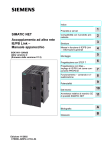
Hardware product version 4, Firmware version V2.1
for SIMATIC S7-400
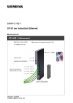
X=
Placeholder for
hardware version
C-PLUG
Firmware version
LEDs
Gigabit interface:
1 x 8-pin RJ-45 jack
Port 1
PROFINET interface:
4 x 8-pin RJ-45 jack
Port 2
Port 3
Port 4
Text with MAC addresses
Release 05/2009
C79000-G8976-C224−04
Notes on the Product
Notes on the Product
Product names
This description contains information on the following product
S
CP 443−1 Advanced
Order number 6GK7 443−1GX20−0XE0
Hardware product version 4 and Firmware version V2.1
for SIMATIC S7−400 / C7−400
Note
In the remainder of this document, the term “CP“ will be used instead of the full
name of the product.
Compatibility with previous versions
Notice
Make sure that you read the information regarding extended functions and
restrictions in Chapter 8 of this manual!
Address label: Unique MAC address preset for the CP
The CP ships with a default MAC address for the 4 Ethernet ports of the
PROFINET interface.
The gigabit interface has its own default MAC address.
The MAC addresses are printed on the housing.
If you configure a MAC address (ISO transport connections), we recommend that
you use the MAC addresses printed on the module for module configuration!
B−2
S
This ensures that you assign a unique MAC address in the subnet!
S
If you replace a module, the MAC address of the predecessor is adopted when
you load the configuration data; configured ISO transport connections remain
operable.
CP 443-1 Advanced for Industrial Ethernet / Manual Part B
Release 05/2009
C79000-G8976-C224−04
Contents
Contents − Part A
S7-CPs for Ind. Ethernet −
Configuring and Commissioning . . . . . . . . . . . . . . . . . . . . .
See general part
Note
Please remember that Part A of the manual also belongs to the description of the
CP. Among other things, this includes the explanation of the safety notices used,
Internet addresses and references as well as information that applies to all
S7−CPs for Industrial Ethernet.
The following version of Part B of the manual belongs to the following version of
the general Part A: 05/2008 or higher
You can also obtain the current general Part A from the Internet at:
http://support.automation.siemens.com/WW/view/en/30374198
Contents − Part B
1
2
3
Properties and Services . . . . . . . . . . . . . . . . . . . . . . . . . . . . . . . . . . . . . . . . . . . . . . . .
B−6
1.1
Properties of the CP . . . . . . . . . . . . . . . . . . . . . . . . . . . . . . . . . . . . . . . . . .
B−6
1.2
Communication services . . . . . . . . . . . . . . . . . . . . . . . . . . . . . . . . . . . . . .
B−7
1.3
Further services and characteristics of the CP . . . . . . . . . . . . . . . . . . . .
B−9
Requirements for Use . . . . . . . . . . . . . . . . . . . . . . . . . . . . . . . . . . . . . . . . . . . . . . . . . .
B−11
2.1
Configuration limits . . . . . . . . . . . . . . . . . . . . . . . . . . . . . . . . . . . . . . . . . . .
B−11
2.2
System environment . . . . . . . . . . . . . . . . . . . . . . . . . . . . . . . . . . . . . . . . . .
B−11
2.3
Configuration . . . . . . . . . . . . . . . . . . . . . . . . . . . . . . . . . . . . . . . . . . . . . . . .
B−14
2.4
Programming . . . . . . . . . . . . . . . . . . . . . . . . . . . . . . . . . . . . . . . . . . . . . . . .
B−15
Installation and Commissioning . . . . . . . . . . . . . . . . . . . . . . . . . . . . . . . . . . . . . . . . .
B−17
3.1
Procedure / steps in installation . . . . . . . . . . . . . . . . . . . . . . . . . . . . . . . .
B−17
3.2
C-PLUG (configuration plug) . . . . . . . . . . . . . . . . . . . . . . . . . . . . . . . . . . .
B−20
3.3
Replacing a module without a programming device . . . . . . . . . . . . . . .
B−22
3.4
Force mode . . . . . . . . . . . . . . . . . . . . . . . . . . . . . . . . . . . . . . . . . . . . . . . . .
B−23
4
Displays . . . . . . . . . . . . . . . . . . . . . . . . . . . . . . . . . . . . . . . . . . . . . . . . . . . . . . . . . . . . . . .
B−24
5
Performance Data / Operation . . . . . . . . . . . . . . . . . . . . . . . . . . . . . . . . . . . . . . . . . . .
B−27
5.1
General characteristic data . . . . . . . . . . . . . . . . . . . . . . . . . . . . . . . . . . . .
B−27
5.2
Characteristic data for S7 communication . . . . . . . . . . . . . . . . . . . . . . . .
B−28
CP 443-1 Advanced for Industrial Ethernet / Manual Part B
Release 05/2009
C79000-G8976-C224−04
B−3
Contents
5.3
5.3.1
5.3.2
SEND/RECEIVE interface . . . . . . . . . . . . . . . . . . . . . . . . . . . . . . . . . . . . .
Characteristic data . . . . . . . . . . . . . . . . . . . . . . . . . . . . . . . . . . . . . . . . . . .
Number of simultaneous SEND/RECEIVE calls . . . . . . . . . . . . . . . . . .
B−29
B−29
B−30
5.4
Characteristics of open TCP/IP communication . . . . . . . . . . . . . . . . . . .
B−32
5.5
5.5.1
5.5.2
PROFINET IO . . . . . . . . . . . . . . . . . . . . . . . . . . . . . . . . . . . . . . . . . . . . . . .
Characteristic data . . . . . . . . . . . . . . . . . . . . . . . . . . . . . . . . . . . . . . . . . . .
How PROFINET IO devices start up with a large operational
configuration . . . . . . . . . . . . . . . . . . . . . . . . . . . . . . . . . . . . . . . . . . . . . . . . .
Reduce the communication allocation reserved for PROFINET IO when
operating alongside other services. . . . . . . . . . . . . . . . . . . . . . . . . . . . . .
B−33
B−33
B−34
5.6
5.6.1
5.6.2
5.6.3
Characteristic data for PROFINET CBA . . . . . . . . . . . . . . . . . . . . . . . . .
Typical values and limit values . . . . . . . . . . . . . . . . . . . . . . . . . . . . . . . . .
Cycle times . . . . . . . . . . . . . . . . . . . . . . . . . . . . . . . . . . . . . . . . . . . . . . . . . .
Reaction times . . . . . . . . . . . . . . . . . . . . . . . . . . . . . . . . . . . . . . . . . . . . . . .
B−35
B−35
B−38
B−39
5.7
Characteristic data for FTP mode . . . . . . . . . . . . . . . . . . . . . . . . . . . . . . .
B−41
5.8
Characteristic data of TCP connections for HTTP . . . . . . . . . . . . . . . . .
B−41
5.9
Characteristic data for the use of Java applets . . . . . . . . . . . . . . . . . . .
B−42
5.10
5.10.1
Memory organization in the CP 443-1 Advanced . . . . . . . . . . . . . . . . . .
Memory distribution . . . . . . . . . . . . . . . . . . . . . . . . . . . . . . . . . . . . . . . . . . .
B−43
B−43
5.11
Characteristic data of the integrated 4-port switch . . . . . . . . . . . . . . . . .
B−44
Using the CP for PROFINET CBA . . . . . . . . . . . . . . . . . . . . . . . . . . . . . . . . . . . . . . . .
B−46
5.5.3
6
7
8
9
B−34
6.1
CBA interface in the user program with FB90 or FB88 . . . . . . . . . . . . .
B−46
6.2
Preparing for configuration with STEP 7 . . . . . . . . . . . . . . . . . . . . . . . . .
B−47
6.3
PROFINET CBA configuration with SIMATIC iMap . . . . . . . . . . . . . . . .
B−48
6.4
Using PROFINET CBA communication and standard communication at the
same time . . . . . . . . . . . . . . . . . . . . . . . . . . . . . . . . . . . . . . . . . . . . . . . . . . .
B−51
The CP as Web server . . . . . . . . . . . . . . . . . . . . . . . . . . . . . . . . . . . . . . . . . . . . . . . . . .
B−53
7.1
HTML process control with IT functions . . . . . . . . . . . . . . . . . . . . . . . . .
B−53
7.2
Web diagnostics − Language setting of the text file for diagnostic
buffer events . . . . . . . . . . . . . . . . . . . . . . . . . . . . . . . . . . . . . . . . . . . . . . . .
B−54
Compatibility with Predecessor Products . . . . . . . . . . . . . . . . . . . . . . . . . . . . . . . .
B−55
8.1
Enhanced functions . . . . . . . . . . . . . . . . . . . . . . . . . . . . . . . . . . . . . . . . . . .
B−55
8.2
Changes . . . . . . . . . . . . . . . . . . . . . . . . . . . . . . . . . . . . . . . . . . . . . . . . . . . .
B−56
8.3
Replacing older modules: spares / upgrading . . . . . . . . . . . . . . . . . . . . .
B−57
Further Notes on Operation . . . . . . . . . . . . . . . . . . . . . . . . . . . . . . . . . . . . . . . . . . . . .
B−62
B−4
9.1
Memory reset / reset to factory defaults . . . . . . . . . . . . . . . . . . . . . . . . .
B−62
9.2
9.2.1
9.2.2
Network settings with Fast Ethernet / gigabit Ethernet . . . . . . . . . . . . .
Fast Ethernet with the PROFINET and gigabit interface . . . . . . . . . . .
Transmission speed of the gigabit interface . . . . . . . . . . . . . . . . . . . . . .
B−65
B−65
B−67
9.3
PROFINET IO mode with IRT communication . . . . . . . . . . . . . . . . . . . .
B−67
CP 443-1 Advanced for Industrial Ethernet / Manual Part B
Release 05/2009
C79000-G8976-C224−04
Contents
9.3.1
Types of synchronization . . . . . . . . . . . . . . . . . . . . . . . . . . . . . . . . . . . . . .
B−67
9.4
Media redundancy . . . . . . . . . . . . . . . . . . . . . . . . . . . . . . . . . . . . . . . . . . . .
B−68
9.5
Time-of-day synchronization . . . . . . . . . . . . . . . . . . . . . . . . . . . . . . . . . . .
B−68
9.6
Recommendations for use with a high communications load . . . . . . . .
B−70
9.7
SNMP agent . . . . . . . . . . . . . . . . . . . . . . . . . . . . . . . . . . . . . . . . . . . . . . . . .
B−71
9.8
Possible security gaps on standard IT interfaces / preventing illegal
access . . . . . . . . . . . . . . . . . . . . . . . . . . . . . . . . . . . . . . . . . . . . . . . . . . . . . .
B−73
9.9
Points to note about IP configuration . . . . . . . . . . . . . . . . . . . . . . . . . . . .
B−74
9.10
Restart after detection of a duplicate IP address in the network . . . . .
B−74
9.11
Prioritized startup in PROFINET IO . . . . . . . . . . . . . . . . . . . . . . . . . . . . .
B−75
9.12
9.12.1
9.12.2
9.12.3
9.12.4
B−76
B−76
B−76
B−77
9.12.5
9.12.6
Interface in the user program . . . . . . . . . . . . . . . . . . . . . . . . . . . . . . . . . .
FC call interface . . . . . . . . . . . . . . . . . . . . . . . . . . . . . . . . . . . . . . . . . . . . . .
Programmed communication connections with FB55 IP_CONFIG . . .
IP access protection with programmed communication connections .
Programmed communications connections − Assigning parameters to
the ports . . . . . . . . . . . . . . . . . . . . . . . . . . . . . . . . . . . . . . . . . . . . . . . . . . . .
Open TCP/IP communication . . . . . . . . . . . . . . . . . . . . . . . . . . . . . . . . . .
Additions to the FC/FB status condition codes . . . . . . . . . . . . . . . . . . . .
9.13
Gigabit interface − special features in STEP 7 . . . . . . . . . . . . . . . . . . . .
B−79
9.14
Attachment to Industrial Ethernet networks . . . . . . . . . . . . . . . . . . . . . .
B−80
9.15
Use of the CP as IP router . . . . . . . . . . . . . . . . . . . . . . . . . . . . . . . . . . . . .
B−80
9.16
Ping: Permitted length of ICMP packets . . . . . . . . . . . . . . . . . . . . . . . . .
B−80
10 Loading New Firmware . . . . . . . . . . . . . . . . . . . . . . . . . . . . . . . . . . . . . . . . . . . . . . . .
B−81
11
Technical Specifications . . . . . . . . . . . . . . . . . . . . . . . . . . . . . . . . . . . . . . . . . . . . . . .
B−83
12 Other Information available about the CP . . . . . . . . . . . . . . . . . . . . . . . . . . . . . . .
B−84
13 References and Literature . . . . . . . . . . . . . . . . . . . . . . . . . . . . . . . . . . . . . . . . . . . . .
B−85
CP 443-1 Advanced for Industrial Ethernet / Manual Part B
Release 05/2009
C79000-G8976-C224−04
B−78
B−78
B−79
B−5
1
Properties and Services
1
1.1
Properties and Services
Properties of the CP
The CP is intended for use in an S7-400 or S7-400H (fault-tolerant) automation
system. It allows the S7-400 / S7-400H to be attached to Industrial Ethernet.
The CP has the following interfaces:
S
PROFINET interface (Ethernet interface ERTEC)
To integrate the CP in a linear bus or ring, to connect a further Ethernet device
or to use media redundancy, and IRT-compliant 4-port ERTEC switch with
autocrossing, autonegotiation and autosensing was integrated in the CP.
Each port of the switch is designed for simple diagnostics and is equipped with
a combined RXD/TXD / LINK dual LED. For special situations, each port can
also be set to a fixed mode manually using STEP 7, for example 10 or
100 Mbps half duplex / full duplex.
S
Gigabit interface
The CP also has an Ethernet interface complying with the gigabit standard
IEEE 802.3ab. This is independent of the ERTEC interface and supports
autocrossing, autonegotiation and autosensing. The gigabit interface can, for
example, be used to connect to a PG/PC or to a higher-level company network.
Each port can be disabled individually in the project engineering.
Note
The following services or characteristics are available only on the PROFINET
interface:
S PROFINET
S Programmed communications connections (FB55 IP_CONFIG).
S Use in fault−tolerant systems (H systems)
B−6
CP 443-1 Advanced for Industrial Ethernet / Manual Part B
Release 05/2009
C79000-G8976-C224−04
1
1.2
Properties and Services
Communication services
The CP supports the following communication services:
S
PROFINET IO controller
PROFINET IO allows direct access to PROFINET IO devices over Industrial
Ethernet. PROFINET IO can only be used via the ports of the PROFINET
interface.
− Prioritized startup
The CP supports prioritized startup. Per PROFINET IO controller, a
maximum of 32 PROFINET IO devices can be configured that support
prioritized startup. Of these 32 IO devices, simultaneous startup times with
values as low as 0.5 s can be achieved by up to 8 IO devices.
− IRT communication (isochronous real time)
IRT communication is possible in PROFINET IO.
If you are using IRT communication, no media redundancy is supported.
− Shared device
As a PROFINET IO controller, individual submodules of an IO device can be
assigned to the CP. When configuring PROFINET IO systems with shared
IO devices, make sure that you read the information in /7/.
S
PROFINET CBA
Use of a SIMATIC S7-400 for Component based Automation on the basis of the
PROFINET standard of the PNO. This standard allows:
− Component technology in automation;
− Communication between intelligent devices is configured graphically instead
of requiring laborious programming
− Vendor-independent, plant-wide engineering.
S
S7 communication with the following functions:
− PG functions
− Operator monitoring and control functions
− Data exchange over S7 connections.
S
S5-compatible communication with the following functions:
− SEND/RECEIVE interface over ISO transport connections;
− SEND/RECEIVE interface over TCP connections, ISO-on-TCP and UDP
connections;
With the SEND/RECEIVE interface via TCP connections, the CP supports
the socket interface to TCP/IP available on practically every end system.
UDP frame buffering on the CP can be disabled during configuration. When
necessary, this allows you to achieve a shorter reaction time between the
arrival of a UDP frame and its evaluation on the CPU.
CP 443-1 Advanced for Industrial Ethernet / Manual Part B
Release 05/2009
C79000-G8976-C224−04
B−7
1
Properties and Services
− Multicast over UDP connection
The multicast mode is made possible by selecting a suitable IP address
when configuring connections.
− FETCH/WRITE services (server services; corresponding to S5 protocol) via
ISO transport connections, ISO-on-TCP connections and TCP connections
Here, the SIMATIC S7-400 with the CP is always the server (passive
connection establishment) while the fetch or write access (client function
with active connection establishment) is always initiated by a SIMATIC S5 or
a device from another range / PC.
− LOCK/UNLOCK with FETCH/WRITE services (CPU-dependent; see
Chapter 2);
S
Open TCP/IP communication
To allow the user program to establish connections with other TCP/IP-compliant
communication partners and to exchange data, STEP 7 provides a UDT for the
connection parameter assignment and four FBs for high-performance data
exchange. The following are supported:
− ISO-on-TCP connections
S
IT functions
− Monitoring devices and process data (HTML process control)
− FTP functions (File Transfer Protocol) for file management and access to
data blocks in the CPU (client and server functions).
If you do not require these functions, you can disable them in the STEP 7
configuration and disable the port (properties dialog of the CP > ”IP Access
Protection” tab).
− Sending E-mail via ESMTP with “SMTP-Auth” for authentication on an
E-mail server
B−8
CP 443-1 Advanced for Industrial Ethernet / Manual Part B
Release 05/2009
C79000-G8976-C224−04
1
1.3
Properties and Services
Further services and characteristics of the CP
S
Media redundancy
Within an Ethernet network with a ring topology, the CP supports the media
redundancy protocol MRP. You can assign the role of redundancy manager to
the CP.
S
Time-of-day synchronization over Industrial Ethernet according to the following
configurable method:
− SIMATIC mode
The CP receives MMS time-of-day messages and synchronizes its local
time.
You can choose whether or not the time of day is forwarded. You can also
decide on the direction in which it is forwarded.
Synchronization using the SIMATIC mode is only possible on the
PROFINET interface.
or
− NTP mode (NTP: Network Time Protocol)
The CP sends time-of-day queries at regular intervals to an NTP server and
synchronizes its local time of day.
The time can also be forwarded automatically to the CPU modules in the S7
station allowing the time to be synchronized in the entire S7 station.
S
Addressable with the factory-set MAC address
To assign the IP address to a new CP (direct from the factory), it can be
accessed using the preset MAC address on the interface being used. Online
address assignment is made in STEP 7.
S
SNMP agent
The CP supports data queries over SNMP version V1 (Simple Network
Management Protocol) according to the MIB II standard.
S
Module access protection
To protect the module form accidental or unauthorized access, protection can
be configured at various levels.
S
IP Access Protection (IP-ACL)
Using IP access protection gives you the opportunity of restricting
communication over the CP of the local S7 station to partners with specific IP
addresses.
CP 443-1 Advanced for Industrial Ethernet / Manual Part B
Release 05/2009
C79000-G8976-C224−04
B−9
1
Properties and Services
S
IP configuration
For the PROFINET interface, you can configure how and with which method
the CP is assigned the IP address, the subnet mask and the address of a
gateway.
As an alternative to STEP 7, you have the option of assigning the connection
configuration via a block interface in the user program (FB55: IP_CONFIG)
(see /10/).
Note: Does not apply to S7 connections.
S
Web diagnostics
With the aid of Web diagnostics, you can read out the diagnostic data from a
station connected via the CP to a PG/PC with an Internet browser.
If you do not require this function, you can disable it in the STEP 7 configuration
and disable the port (properties dialog of the CP > ”IP Access Protection” tab).
S
Diagnostic Buffer Extract Request
With the aid of a Web browser, the CP supports the option of obtaining an
extract of the diagnostic buffer containing the most recent diagnostic events of
the CPUs and CPs located in the same S7 station as the CP.
S
Connection diagnostics with FC10 AG_CNTRL
With the FC10 AG_CNTRL function, you can diagnose connections. When
necessary, you can activate or deactivate connections using the FC or initiate
reestablishment of a connection.
S
S5/S7 addressing mode
The addressing mode can be configured for FETCH/WRITE access as the S7
or S5 addressing mode (S7 addressing mode only for data blocks / DBs).
S
IP double addressing detected in the network
To save you time-consuming troubleshooting in the network, the CP detects
double addressing in the network.
The reaction of the CP when double addressing is detected varies as follows:
− CP during startup
The CP remains in STOP mode.
− CP in RUN mode
There is an LED indication (BUSF LED) and an entry in the diagnostic
buffer; the CP remains in RUN mode.
B−10
CP 443-1 Advanced for Industrial Ethernet / Manual Part B
Release 05/2009
C79000-G8976-C224−04
2
2
2.1
Requirements for Use
Requirements for Use
Configuration limits
When using the CP type described here, the following limits apply within a rack:
S
Max. number of CPs 14
S
Number of CPs operating as PROFINET IO controllers: 4
S
Number of CPs that can be configured for PROFINET CBA communication
within an S7 station: 1 (system property)
Notice
S The number of CPs operating as PROFINET IO controllers depends on the
number of CP 443-5 Extended modules operating as DP masters in the S7-400
station. A total of 10 CPs can be operated as controllers for the distributed I/O
(PROFINET IO controllers or DP masters); of those, however, only up to 4 as
PROFINET IO controllers.
S Please note the following regarding multiprocessor mode: When operating the
CP as a PROFINET IO controller, only the process image of the assigned CPU
can be distributed via the CP.
2.2
System environment
General Requirements
S
The CP has been released with CPUs as of firmware version 4.1.
CPUs with firmware version 4.0 must be upgraded to V4.1.
S
Open TCP/IP communication is supported by all CPUs as of firmware version
V4.1.
S
The function block FB90 (PN_InOut_Fast) for PROFINET CBA is supported by
all CPUs as of firmware version V4.1.
H−CPUs do not support PROFINET CBA.
S
The full range of functions (MRP, IRT, prioritized startup) is available only with
CPUs as of firmware version 5.2.
Note also the information on the required version of the STEP 7 configuration
tool in Section 2.3.
S
CPUs with firmware version 5.0 must be upgraded to V5.1.
CP 443-1 Advanced for Industrial Ethernet / Manual Part B
Release 05/2009
C79000-G8976-C224−04
B−11
2
Requirements for Use
Restrictions for CPUs with older firmware versions
S
With CPUs with firmware version V4.1, the CP only has the range of functions
of the predecessor module CP 443-−1 Advanced (6GK7 443-1EX41-0XE0)
S
The use of the blocks FC53 “AG_SSEND” and FC63 “AG_SRECV” is possible
only on CPUs with a firmware version V5.1 or higher.
S
On CPUs with a firmware version up to and including V5.1, PROFINET IO
mode is not possible.
Table of compatible CPUs
The CP is supported by the S7-400 CPUs with the order numbers and firmware
versions as shown in the following table.
The table also contains the following information:
Table 2-1
S
The number of CPs that can be operated with one CPU
S
The number of CPU resources for SEND/RECEIVE calls;
S
Which CPUs support the LOCK/UNLOCK function with the FETCH/WRITE
services
S
Which CPU supports operation of the CP as PROFINET IO controller;
CPU data relevant to use of the CP
CPU
Order number of
th CPU:
the
CPU
6ES7...
as of firmware version
Multiprocessing possible
Max. number of CPs
CPU resources for
SEND-/RECEIVE jobs 1)
LOCK/UNLOCK
PROFINET IO
4)
CPU 412−1
..412−1XF04−0AB0
V4.1
+ 2)
14
24
+
−
CPU 412−1
..412−1XJ05−0AB0
V5.1
+ 2)
14
24
+
−
as of
V5.2
+
2)
14
24
+
+
V4.1
+ 2)
14
24
+
−
V5.1
+
2)
14
24
+
−
as of
V5.2
+ 2)
14
24
+
+
V5.1
+ 2)
14
24
+
−
as of
V5.2
+ 2)
14
24
+
+
V4.1
+ 2)
14
24
+
−
CPU 412-2
CPU 412-2
CPU 414-2
CPU 414-3
B−12
..412−2XG04−0AB0
..412−2XJ05−0AB0
..414−2XK05−0AB0
..414−3XJ04−0AB0
CP 443-1 Advanced for Industrial Ethernet / Manual Part B
Release 05/2009
C79000-G8976-C224−04
2
Table 2-1
Requirements for Use
CPU data relevant to use of the CP
CPU
Order number of
the CPU:
6ES7...
as of firmware version
Multiprocessing possible
Max. number of CPs
CPU resources for
SEND-/RECEIVE jobs 1)
LOCK/UNLOCK
PROFINET IO
4)
CPU 414-3
..414−3XM05−0AB0
CPU 414-3 PN/DP
CPU 416-2
..414−3EM05−0AB0
..416−2XK04−0AB0
CPU 416-2
..416−2XN05−0AB0
CPU 416F−2
CPU 416F−2
..416−2FK04−0AB0
..416−2FN05−0AB0
V5.1
+ 2)
14
24
+
−
as of
V5.2
+ 2)
14
24
+
+
V5.1
+
14
24
+
−
as of
V5.2
+
14
24
+
+
V4.1
+ 2)
14
64
+
−
V5.1
+
2)
14
64
+
−
as of
V5.2
+ 2)
14
64
+
+
V4.1
+ 2)
14
64
+
−
V5.1
+
2)
14
64
+
−
as of
V5.2
+
2)
14
64
+
+
CPU 416-3
..416−3XL04−0AB0
V4.1
+ 2)
14
64
+
−
CPU 416-3
..416−3XR05−0AB0
V5.1
+ 2)
14
64
+
−
as of
V5.2
+
2)
14
64
+
+
V5.1
+ 2)
14
64
+
−
as of
V5.2
+ 2)
14
64
+
+
V5.1
+ 2)
14
64
+
−
as of
V5.2
+ 2)
14
64
+
+
V4.1
+ 2)
14
64
+
−
V5.1
+
2)
14
64
+
−
as of
V5.2
+ 2)
14
64
+
+
V4.5
+ 2)
14
64
+
−
V4.5
+
2)
14
64
+
−
+
2)
14
64
+
−
+
2)
14
64
+
−
CPU 416-3 PN/DP
CPU 416F−3 PN/DP
CPU 417-4
..416−3ER05−0AB0
..416−3FR05−0AB0
..417−4XL04−0AB0
CPU 417-4
..417−4XT05−0AB0
CPU 412-3H 3)
CPU 414H
3)
CPU 417H
3)
CPU 417H
3)
..412-3HJ14-0AB0
..414-4HM14-0AB0
..414-4HR14-0AB0
..417−4HT14−0AB0
V4.5
V4.5
Legend:
+ => The feature is supported / the specified mode is possible
=> the feature is not supported / the specified the mode is not possible
CP 443-1 Advanced for Industrial Ethernet / Manual Part B
Release 05/2009
C79000-G8976-C224−04
B−13
2
Requirements for Use
1)
The calculation of the maximum number of SEND/RECEIVE calls that can be used simultaneously per CP
is described in Section 5.3.2.
2)
When using the CP as a PROFINET IO controller, multiprocessor mode is not supported, in other words,
only the process image of the assigned CPU can be distributed via the CP (Note: this does not affect
communication protocols running at the same time in multiprocessor mode).
3)
When operating with H-CPUs, the SSEND / SRECV mode on the SEND/RECV interface is not supported.
H−CPUs do not support PROFINET.
4)
The PROFINET IO mode shared device requires a CPU as of Version V5.3.
2.3
Configuration
The following version of STEP 7 is required:
Table 2-2
CP 443-1 Advanced functionality
STEP 7 version
as of V5.4 + Service Pack 4
The full functionality as described in this document can be used.
Downloading configuration data
It is possible to download the configuration data to the CP via MPI or
LAN/Industrial Ethernet. Downloading is possible over the PROFINET or the
gigabit interface of the CP.
Project engineering for PROFINET CBA
To be able to work in the PROFINET CBA environment, you require the SIMATIC
iMap engineering tool.
SIMATIC iMap requires a connection over Industrial Ethernet (TCP/IP protocol).
The following SIMATIC iMap project engineering software is required:
Table 2-3
SIMATIC iMap version
as of V3.0 + Service Pack 1
CP 443-1 Advanced functionality
The full functionality of the device can be used as of hardware
version 1 and firmware version V1.
Table 2-4
Version STEP 7 add-on
as of V3.0 + Service Pack 4
B−14
CP 443-1 Advanced functionality
The full functionality as described in this document can be used.
CP 443-1 Advanced for Industrial Ethernet / Manual Part B
Release 05/2009
C79000-G8976-C224−04
2
Requirements for Use
To operate PROFINET CBA, you require the current service packs of SIMATIC
iMap containing the current versions of the function blocks FB88/FB90:
SIMATIC iMap V3.0 or higher − Download Service Pack 1:
SIMATIC iMap STEP 7 add-on V3.0 or higher − Download Service Pack 4:
http://support.automation.siemens.com/WW/view/en/10805413
2.4
Programming
Programming − FCs / FBs
For some communications services, there are pre-programmed blocks (FCs/FBs)
available as the interface in your STEP 7 user program.
Please refer to the documentation of the FCs / FBs in the online help of STEP 7 or
in the manual /10/.
Notice
We recommend that you always use the latest block versions for all module types.
You will find information on the current block versions and the current blocks to
download from the Internet in our customer support.
http://support.automation.siemens.com/WW/view/en/8797900
With the older module types, this recommendation assumes that you are using the
latest firmware for the particular block type.
Using blocks for the SEND/RECEIVE interface
For data transfer on the SEND/RECEIVE interface, there are FCs for short and
long blocks of data:
For fast data transmission up to a data length of 1452 bytes, the SPEED
SEND/RECEIVE blocks AG_SSEND FC53 and AG_SRECV FC63 are supported.
Table 2-5
Requirements
Function
Transfer of data fields <= 240 bytes
S You require the blocks AG_SEND FC5 and AG_RECV
Transfer of data fields > 240 bytes
S You require the blocks AG_LSEND FC50 and
Accelerated transfer of blocks of data <=
1452 bytes
S You require the blocks AG_SSEND FC53 and
FC6 or alternatively the blocks AG_LSEND FC50
and AG_ LRECV FC60.
AG_LRECV FC60.
AG_SRECV FC63.
CP 443-1 Advanced for Industrial Ethernet / Manual Part B
Release 05/2009
C79000-G8976-C224−04
B−15
2
Requirements for Use
Note
Note that in multicomputing mode, communication using SPEED-SEND/RECV is
possible only via the CP assigned to the CPU.
Note
Note the recommendations in Section 9.6 on operation with a higher
communications load.
B−16
CP 443-1 Advanced for Industrial Ethernet / Manual Part B
Release 05/2009
C79000-G8976-C224−04
3
3
Installation and Commissioning
Installation and Commissioning
3.1
Procedure / steps in installation
Caution
When installing the CP for use as a PROFINET IO controller, note the following
points about the power supply:
When using the CP in the central rack or in a universal rack operating as central
rack, you should not insert or remove the CP when the power is on. If you remove
the CP when the power supply is on, the CPU changes to STOP and indicates
“I/O error”.
After inserting the module with power applied, it is essential to turn the power
supply off and on again.
Note:
If the CP is operated without PROFINET IO, it is possible to insert and remove the
CP when the power is no without affecting the CPU.
Installing the CP involves the following steps.
Step
Explanation / meaning
1. Turn off the power supply when you have
configured the CP for PROFINET IO
communication.
If the CP is configured as a PROFINET IO
controller and you remove or insert the module, the
CPU assigned in the rack changes to STOP.
2. Inserting the CP: Fit in the CP onto the rack
from the top and push in at the bottom.
The CP can be plugged into all racks with slots for
P and K bus attachment.
Notice
When using the universal rack UR1 or UR2 as an expansion rack, a communication bus transceiver is
necessary!
Suitable slots in the rack:
With the exception of the slots reserved for the
power supply, the CP can be operated in all slots
with a P and K bus attachment.
3. Secure the CP with screws.
4. Turn the power supply on again.
5. Connect the CP to Industrial Ethernet over an
RJ-45 jack.
CP 443-1 Advanced for Industrial Ethernet / Manual Part B
Release 05/2009
C79000-G8976-C224−04
You will find examples of network attachments in
the general Part A of this manual.
B−17
3
Installation and Commissioning
Step
Explanation / meaning
6. Where necessary, connect other components to For small local area networks or for attaching
the remaining free RJ-45 jacks.
several Ethernet devices, a 4-port switch has been
integrated in the CP 443-1 Advanced.
With the autocrossing mechanism integrated in the
switch, it is possible to establish the connection
from a laptop or PG directly using standard cables.
A crossover cable is not necessary.
Please note the following points:
S Manual configuration
If a port is set to manual configuration and
autonegotiation is disabled, the autocrossing
mechanism is also disabled for this port. The
port then behaves like the interface of a switch.
Which cable you can use depends on the
partner device.
As default, the ports are set for automatic
configuration.
For more detailed information, refer to Section
10.2
S Connecting switches
If you connect further switches, make sure that
no ring is formed in the network.
For an MRP configuration, refer to the guidelines
for setting up MRP in the general Part A of this
manual.
You will find examples of network attachments in
the general part of this manual.
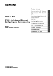
CP 443-1 Advanced
Integrated switch with
external ports
Switch
Switch
Switch
B−18
CP 443-1 Advanced for Industrial Ethernet / Manual Part B
Release 05/2009
C79000-G8976-C224−04
3
Step
7. The remaining steps in commissioning involve
downloading the configuration data and user
programs.
Requirements:
You have configured the CP in a STEP 7
project with HW Config and NetPro for the
services you want to use.
Installation and Commissioning
Explanation / meaning
You can connect the PG when configuring the CP
as follows:
S via MPI
S via Industrial Ethernet
For further details, refer to the general Part A of
this manual:
− for initial addressing (node initialization);
− downloading the defined configuration
The PG/PC requires a LAN attachment, for
example via a CP 1613 or CP 1411 and must have
the necessary software (for example the S7 1613
package or SOFTNET IE). The TCP/IP protocol or
ISO protocol must be installed. The protocol used
must then be applied to the S7ONLINE access
point.
8. Use the diagnostic functions during
commissioning and to analyze problems.
The following options are available:
S Hardware Diagnostics and Troubleshooting
with STEP 7;
S Communication diagnostics with NCM S7
Diagnostics
S Standard information using HW Config
S Web diagnostics
9. Optional when using with PROFINET CBA:
Download PROFINET CBA component
If the S7 station in which the CP is operated is used
as a PROFINET CBA component, the
interconnections are downloaded using SIMATIC
iMap; with standard components, programs and
configuration data are also downloaded with
SIMATIC iMap.
For more detailed information, refer to the topic
“Using the CP with PROFINET CBA”.
Notice
If you use the CP as a replacement (for example for a CP 443–1 IT “GX11”) with
an older CPU, the default communication load setting of 20% for the CPU can lead
to overload. In this case, you should set the communication load for the CPU in
STEP 7/HW Config (parameter “Scan cycle load from communication”) to a lower
value − for example 10%.
With CPUs as of version V5.1, this is unnecessary.
CP 443-1 Advanced for Industrial Ethernet / Manual Part B
Release 05/2009
C79000-G8976-C224−04
B−19
3
Installation and Commissioning
3.2
C-PLUG (configuration plug)
Exchangeable C-PLUG
The CP has an exchangeable configuration plug (C-PLUG). This can store up to
32 MB of data in nonvolatile memory.
S
The retentive parameters include:
− IP address and IP parameters
− A newly set MAC address
− LAN settings
− Interconnection information for PROFINET CBA
− SNMP Variables (modifiable)
S
Data in the flash file system (see also Flash Area in Section 5.10 Memory
Organization)
This configuration plug simplifies replacement of modules. By simply exchanging
the plug, all the data can be transferred to the replacement module.
Notice
The CP will not start up without a C-PLUG!
Area of application
The C-PLUG is an exchangeable medium for storing configuration and project
engineering data of the basic device (CP 443-1 Advanced). This means that
configuration data remains available if the basic device is replaced.
Principle
The power is supplied by the basic device. When powered down, the C-PLUG
retains all data permanently.
B−20
CP 443-1 Advanced for Industrial Ethernet / Manual Part B
Release 05/2009
C79000-G8976-C224−04
3
Installation and Commissioning
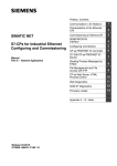
Inserting in the C-PLUG slot
The slot for the C-PLUG is on the rear panel of the device.
The C-PLUG is inserted in the receptacle.
Figure 3-1
Fitting the C-PLUG in the CP and removing it from the CP with a screwdriver
Function
If the C-PLUG has not yet been written to (as shipped), when the device starts up,
all the configuration data of the CP is saved automatically on it.
If the C-PLUG is inserted, the basic device automatically uses the configuration
data of the C-PLUG. This assumes that the data was written by a compatible
device type.
If a fault occurs, the basic device can then be replaced much faster and more
simply. If a device needs to be replaced, the C-PLUG is simply taken from the
failed component and inserted in the replacement. As soon as it starts up, the
replacement automatically has the same device configuration as the failed device.
Using a C-PLUG with old configuration data
Use only C-PLUGs that are formatted for the CP 443-1 Advanced. C-PLUGs that
have already been used and formatted in other device types must first be
formatted for the CP 443-1 Advanced.
You do this with STEP 7 / NCM Diagnostics. For more detailed information, refer to
the online help in the topic “General Diagnostics Functions − C-PLUG Diagnostics
Object”.
After formatting, all data areas are deleted on the C-PLUG. The project
engineering is adopted by the CPU only after reloading or after turning on the
power supply again.
Removing the C-PLUG
It is only necessary to remove the C-PLUG if a fault occurs on the CP (see
Figure 3-1).
CP 443-1 Advanced for Industrial Ethernet / Manual Part B
Release 05/2009
C79000-G8976-C224−04
B−21
3
Installation and Commissioning
Diagnostics
Inserting a C-PLUG containing the configuration of an incompatible device type or
general malfunctions of a C-PLUG are signaled by the diagnostic mechanisms of
the CP (F LED red).
3.3
Replacing a module without a programming device
General procedure
The configuration data of the CP is stored on the CPU. This makes it possible to
replace this module with a module of the same type (identical order number)
without a PG.
Note
When setting the ISO protocol, remember that MAC address set previously during
configuration is transferred by the CPU to the new CP module.
For information on replacing previous modules, please refer to the section
“Compatibility”.
Notice
The “Replace module without PG” functionality (configuration data stored on the
CPU) can no longer be used fully after downloading PROFINET CBA
interconnections since the interconnection information is stored only on the CP.
You have the following two options:
S Using the C-PLUG in new modules
You insert the previously used C-PLUG in the replacement module;
interconnection information is then available again.
S Using a new module with a new C-PLUG
After replacing a module, you must download the interconnection information to
the new CP using SIMATIC iMap.
Module replacement: Special feature of IP address assignment from a DHCP server
During configuration of the CP you can specify the IP configuration in the
properties dialog; one option is to obtain the IP address from a DHCP server.
B−22
CP 443-1 Advanced for Industrial Ethernet / Manual Part B
Release 05/2009
C79000-G8976-C224−04
3
Installation and Commissioning
Notice
When replacing modules, remember that the factory-set MAC address of the new
module is different from the previous module. When the factory-set MAC address
of the new module is sent to the DHCP server, this will return either a different or
no IP address.
Ideally, you should therefore configure IP as follows:
Always configure a client ID if you want to obtain the same IP address from the
DHCP server after replacing the module.
If you have configured a new MAC address instead of the factory-set MAC
address (generally the exception, for example when using the ISO protocol), the
DHCP server always receives the configured MAC address and the CP obtains
the same IP address as the replaced module.
3.4
Force mode
You can change the mode of the CP between RUN and STOP using the STEP 7 /
NCM S7 engineering software:
S
Switch from STOP to RUN:
The CP reads the configured and/or downloaded data into the work memory
and then changes to the RUN mode.
S
Switch from RUN to STOP:
The CP changes to STOP. Established connections (ISO transport,
ISO-on-TCP, TCP, UDP connections) are terminated (transitional phase with
LED display “STOPPING”);
The reaction is as follows in STOP:
− The communications connections mentioned above are terminated;
− The configuration and diagnostics of the CP is possible (system connections
for configuration, diagnostics, and PG channel routing are retained);
− Functions for topology discovery continue to be supported (LLDP frames are
sent).
− The downloading of interconnections for PROFINET CBA communication is
not possible;
− FTP access to the file system is possible
− HTTP access is possible
− The routing function is active
− The time of day is not forwarded
− PROFINET IO is disabled.
CP 443-1 Advanced for Industrial Ethernet / Manual Part B
Release 05/2009
C79000-G8976-C224−04
B−23
4
Displays
4
Displays
LED display
The display on the front panel consists of 13 LEDs that indicate the operating
mode and communication status.
INTF
EXTF
BUS1F
BUS2F
TXD
RXD
Front
panel:
X1P1
MAINT
X2P1
X2P2
X2P3
X2P4
RUN
STOP
The LEDs have the following meaning:
S
INTF:
Internal fault
S
EXTF:
External fault
S
BUS1F: Bus fault gigabit interface
S
BUS2F: Bus fault PROFINET interface
S
TXD:
Frame traffic (sending) over Ethernet
(not relevant for PROFINET IO data)
S
RXD:
Frame traffic (receiving) over Ethernet
(not relevant for PROFINET IO data)
S
MAINT: Maintenance necessary (diagnostic buffer)
S
RUN:
S
STOP: STOP mode
S
X1 P1:
S
X2P1, X2P2,
X2P3, X2P4: Link status / activity of Ethernet port 1, 2, 3, 4
RUN mode
Link status / activity of the Ethernet gigabit port
Unlabeled LEDs have no significance (only relevant for diagnostics)
B−24
CP 443-1 Advanced for Industrial Ethernet / Manual Part B
Release 05/2009
C79000-G8976-C224−04
4
Displays
CP mode / LED display patterns
INTF
(red)
EXTF
(red)
BUS1F /
BUS2F
(red) *)
RUN
(green)
STOP
(yellow)
CP Operating Mode
Starting up (STOP->RUN)
Running (RUN)
Stopping (RUN->STOP)
Stopped (STOP)
In the STOP mode configuring and
performing diagnostics on the CP remain
possible.
STOP with internal error or memory reset.
(for example IP double addressing
detected during startup of the CP in
network)
The following applies in this status:
S The CPU or intelligent modules in the
rack remain accessible using PG
functions (over MPI or the ISO
protocol).
S SNMP functionality and access over
HTTP or FTP are not possible.
S No link (on any port)
−
−
−
or
S Double IP address detected during
CP operation.
RUN with external error; One or more IO
devices are not obtainable.
(only BUS2F)
S RUN with external error; Diagnostic
interrupt from one or more IO devices
is pending. IO device diagnostics will
provide detailed information.
or
S Event indication in conjunction with
the MRP function; The CP diagnostic
buffer contains detailed information.
Module fault / system error
Legend:
(colored) on
off
(colored) flashing
“−” any
*) The behavior applies to BUS1F and BUS2F if there is no restriction listed in the “CP mode” column.
Firmware download − LED display patterns
The LED display patterns when downloading the firmware are described in Chapter 10.
CP 443-1 Advanced for Industrial Ethernet / Manual Part B
Release 05/2009
C79000-G8976-C224−04
B−25
4
Displays
The “MAINT“ LED (yellow)
Notice
When the “MAINT” LED lights up, important error messages and/or diagnostic
interrupts have occurred. The CP continues in RUN mode.
Check the entries in the diagnostic buffer of the device.
CP communications status / LED display patterns
LED
Display status
Meaning
green
TXD (green)
CP sending over Ethernet.
Note:
Sending over PROFINET IO is not
signaled here.
green
RXD (green)
CP is receiving over Ethernet
Note:
Receiving over PROFINET IO is not
signaled here.
Port has no connection over Ethernet.
X1P1
X2P1 / X2P2 / X2P3 /
X2P4
(g
y
)
(green / yellow)
green
Existing connection over port to Ethernet
(LINK status).
green /
yellow
LED flashes yellow, steady light green:
Port sending / receiving over Ethernet or
PROFINET IO.
Note:
All received / sent frames are signaled for
the specific ports, This includes those that
are simply forwarded by the switch.
yellow
Legend:
(colored) on
off
Continuous data transfer at the port over
Ethernet (on ERTEC ports for example
PROFINET IO).
(colored) flashing
Module identification
Using the SIMATIC Manager, you can search for and identify the module initially by
browsing the connected network with the menu “PLC” > “Edit Ethernet Node”. If
you select the found node in the “Browse Network” dialog, and then click -“flash”,
all the port LEDs of the PROFINET interface flash.
B−26
CP 443-1 Advanced for Industrial Ethernet / Manual Part B
Release 05/2009
C79000-G8976-C224−04
5
5
Performance Data / Operation
Performance Data / Operation
Note
Measurements of transmission and reaction times in Ethernet, PROFIBUS and
PROFINET networks for a series of configurations can be found on the Internet at
the following address:
http://support.automation.siemens.com/WW/view/en/25209605
5.1
General characteristic data
Table 5-1
Characteristic
Explanation / values
Total number of connections on Industrial Ethernet
In total (S7 connections + SEND/RECEIVE
connections + CBA + FTP + HTTP ), the number of
connections is restricted to 128.
Example
You can, for example, operate:
64 S7 connections or 62 H connections
30 ISO-on-TCP connections
10 TCP connections
10 UDP connections
8 ISO transport connections,
If you require FTP and HTTP access at the same time,(for FTP 2 x TCP
connections and for HTTP 4 x TCP connections; see Section 5.7).
CP 443-1 Advanced for Industrial Ethernet / Manual Part B
Release 05/2009
C79000-G8976-C224−04
B−27
5
Performance Data / Operation
5.2
Characteristic data for S7 communication
Table 5-2
Characteristic
Total number of S7 connections on Industrial
Ethernet
Explanation / values
128 max.
of those max. 62 H connections
LAN interface - data field length generated by CP
per protocol data unit
S sending
S receiving
S Number of PG connections
S Number of OP connections
Repercussions of the number of SEND/RECV
connections in SPEED SEND/RECV mode
B−28
480 bytes / PDU
480 bytes / PDU
2 max.
30 max.
Note the following with SPEED SEND/RECEIVE:
Using SSEND/SRECV reduces the possible
configuration limits of S7 communication with each
configured SEND/RECV connection in SPEED
SEND/RECV mode.
CP 443-1 Advanced for Industrial Ethernet / Manual Part B
Release 05/2009
C79000-G8976-C224−04
5
5.3
5.3.1
Performance Data / Operation
SEND/RECEIVE interface
Characteristic data
The SEND/RECEIVE interface provides access to communication over TCP,
ISO-on-TCP, ISO transport, E-mail, and UDP connections.
The following characteristics are important:
Table 5-3
Characteristic data of the SEND/RECEIVE interface
Explanation / values
Characteristic
Number of SEND/RECEIVE connections
S
S
S
S
TCP connections: 1...64 1) 2)
ISO-on-TCP connections 1 to 64
ISO transport connections 1...64
UDP connections (specified and free) configurable in total
1 to 64 (of those, up to 48 multicast mode)
S E-mail connection: 1
S Max. number of connections in total
(ISO transport + ISO-on-TCP
+ TCP+ UDP + E-mail) <= 64
Refer to the example in Section 5.1
1)
Note:
The flow control on TCP connections cannot control
permanent overload of the receiver. You should therefore
make sure that the processing capabilities of a receiving CP
are not permanently exceeded by the sender (approximately
150-200 messages per second).
2) TCP
connections for FTP
Of the available to CP connections, a maximum of 20 TCP
connections can be configured / used with the “Use FTP
protocol“ option (see Section 5.7).
Number of SEND/RECV connections in
SPEED SEND/RECV mode
The number depends on the CPU type being used.
S Per CPU 412/414 maximum 30
S Per CPU 416/417 maximum 62
Maximum data length for AG_SEND and AG_SEND and AG_RECV were shipped with predecessors of
AG_RECV functions (FCs)
the CP and allow the transfer of data fields with a length from
1 to 240 bytes. The version of the CP described here
continues to support these blocks.
Maximum data length for AG_LSEND
and AG_LRECV blocks
AG_LSEND and AG_LRECV allow the transfer of data fields
with the following lengths:
1. ISO-on-TCP, TCP, ISO Transport: 1 to 8192 bytes
2. UDP: 1 to 2048 bytes
3. E-mail (job header + user data): 1 to 8192 bytes
CP 443-1 Advanced for Industrial Ethernet / Manual Part B
Release 05/2009
C79000-G8976-C224−04
B−29
5
Performance Data / Operation
Table 5-3
Characteristic data of the SEND/RECEIVE interface, Fortsetzung
Characteristic
Maximum data length for AG_SSEND
and AG_SRECV blocks
Explanation / values
AG_SSEND and AG_SRECV allow the transfer of data fields
with the following lengths:
1. ISO-on-TCP, TCP, ISO Transport: 1 to 1452 bytes
2. UDP: 1 to 1452 bytes
Restrictions for UDP
S Transfer is not confirmed
The transmission of UDP frames is unconfirmed, in other
words the loss of messages is not detected or displayed by
the send blocks (AG_SEND or AG_LSEND).
S No reception of UDP broadcast
To avoid overload due to high broadcast load, the CP does
not allow reception of UDP broadcasts.
As an alternative, use the multicast function over a UDP
connection. This allows you to register the CP as a node in a
multicast group.
S UDP frame buffering
Length of the frame buffer with buffering enabled:
2 KB
Note:
Following a buffer overflow, newly arriving frames are
discarded.
LAN interface - max. data field length
generated by CP per protocol data unit
S sending
ISO transport, ISO-on-TCP, TCP:
− 400 bytes / TPDU with AG_SEND / AG_LSEND
− 1452 bytes / TPDU with AG_SSEND
S receiving
− ISO transport: 512 bytes / TPDU
− ISO-on-TCP: 1452 bytes / TPDU
− TCP: 1452 bytes / TPDU
5.3.2
Number of simultaneous SEND/RECEIVE calls
The number of SEND/RECEIVE calls that can be used at the same time is limited
both by the CPU and by the CP.
If the maximum number of simultaneous SEND/RECEIVE calls is exceeded, the
value 8302H (no receive resources) is indicated in the STATUS of the surplus
SEND functions. This can, for example, happen when too many SEND/RECEIVE
calls are sent at the same time in OB1.
Limitation by the CPU
In productive operation, the number of simultaneous SEND/RECEIVE calls
depends on the CPU resources being used. Note the information on the available
CPU resources in Section 2.2.
B−30
CP 443-1 Advanced for Industrial Ethernet / Manual Part B
Release 05/2009
C79000-G8976-C224−04
5
Performance Data / Operation
The following CPU resources are required:
S
Per SEND job short (FC5) or long (FC50):
1 resource
S
Per RECEIVE job short (FC6):
1 resource
S
Per RECEIVE job long (FC60):
2 resources
S
Per SPEED SEND/RECV job (FC53, FC63):
0 resources
Limitation by the CP
A maximum of 64 SEND/RECEIVE connections can be operated by the CP.
At an assignment of 1 CP per CPU, the maximum number of SEND/RECEIVE
calls that can be used at one time is limited as follows:
S
SEND calls short (FC5) or long (FC50):
max. 32*) / 12**) per CPU
S
RECEIVE calls short (FC6):
max. 64*) / 24**) per CPU
S
RECEIVE calls long (FC60):
variable ***)
*) The values apply to the CPU 416 and CPU 417.
*) The values apply to the CPU 412 and CPU 414.
***)The number of FC60s that can be used at the same time depends on the
number of SEND calls active at the same time (see Tables 5-4 and 5-5).
Table 5-4
Dependency of the maximum number of RECEIVE calls long (FC60) used at the same time
on the number of SEND calls (CPU 412/414)
Number of
simultaneous SEND
calls
0
1
2
3.
4
5
6
7
8
9
10
11
12
Max. number of
simultaneous FC60s
per CPU 412/414
19
18
17
16
15
14
13
12
11
10
9
CP 443-1 Advanced for Industrial Ethernet / Manual Part B
Release 05/2009
C79000-G8976-C224−04
B−31
5
Performance Data / Operation
Table 5-5
Dependency of the maximum number of RECEIVE calls long (FC60) used at the same time
on the number of SEND calls (CPU 416/417)
Number of
simultaneous SEND
calls
0
1
2
3.
4
5
6
7
8
9
10
11
12
13
14
15
16
Max. number of
simultaneous FC60s
per
CPU 416/417/41x–H
51
50
49
48
47
46
45
44
43
42
41
40
39
38
Number of
simultaneous SEND
calls
17
18
19
20
21
22
23
24
25
26
27
28
29
30
31
32
Max. number of
simultaneous FC60s
per
CPU 416/417/41x–H
37
36
35
34
33
32
31
30
29
28
27
26
25
The maximum number of SPEED SEND/RECEIVE calls that can be used
simultaneously (FC53, FC63) depends only on the CPU (see above).
5.4
Characteristics of open TCP/IP communication
Table 5-6
Characteristic
Number of dynamically generated connections
over Industrial Ethernet
Max. data length
B−32
Explanation / values
S ISO-on-TCP connections 1 to 64
1452 bytes
CP 443-1 Advanced for Industrial Ethernet / Manual Part B
Release 05/2009
C79000-G8976-C224−04
5
5.5
Performance Data / Operation
PROFINET IO
5.5.1
Characteristic data
PROFINET IO communication of the CP is IRT-compliant. The CP supports the
following maximum configuration as a PROFINET IO controller:
Table 5-7
Characteristic
Explanation / values
Number of CPs that can be operated as PROFINET IO controllers
within an S7-400 station
4
Number of possible PROFINET IO devices *)
128, of which
S 128 in IRT mode
S 32 in ”Prioritized startup”
mode
Size of the input area over all PROFINET IO devices
8 Kbytes max.
Size the output area over all PROFINET IO devices
8 Kbytes max.
Size of the IO data area per submodule of a module in an IO device
S Inputs
S Outputs
240 bytes
240 bytes
This information also applies to operation with a shared device
Size of the consistency area for a submodule
240 bytes
*) The number of operable PROFINET IO devices can be reduced if the devices being used require extensive
configuration and parameter assignment data due to large numbers of submodules. In this case, the
memory on the CP will not be adequate and you will receive a message in the diagnostic buffer about lack
of resources when downloading the configuration data.
Notice
Note the following for PROFINET IO: If you use modules with >=32 bytes of
input/output data, this can lead to I/O access errors; access errors are entered in
the diagnostic buffer of the CPU.
These I/O errors occur during operation only in the “consistent user data“ mode
and at a low OB1 cycle time.
CP 443-1 Advanced for Industrial Ethernet / Manual Part B
Release 05/2009
C79000-G8976-C224−04
B−33
5
Performance Data / Operation
5.5.2
How PROFINET IO devices start up with a large operational
configuration
When operating the module with a large configuration (up to 128 communication
connections and up to 128 PROFINET IO devices), it may take several minutes
when the station starts up before all PROFINET IO devices have received
configuration data from the PROFINET IO controller. The IE/PB Link PN IO
operating as a PROFINET IO device is particularly affected by this.
To ensure that the CPU does not interrupt the distribution of project engineering
data in this situation, the parameter assignment monitoring time must be increased
on the CPU.
Possible remedy: Reduce the size of the configuration (for example, distribution on
several CPs).
5.5.3
Reduce the communication allocation reserved for
PROFINET IO when operating alongside other services.
If cyclic data exchange over PROFINET IO is operating at the same time on the
same Ethernet subnet, set the parameter “Communication component for
PROFINET IO“ in the properties dialog of the PROFINET IO system to a value
<100%.
Reason: At the (default) setting 100%, the communication time is reserved
primarily for PROFINET IO data exchange. Reducing the communication
component for PROFINET IO increases the system-wide update time for
PROFINET IO and creates additional time on the CP for processing other
communication services.
B−34
CP 443-1 Advanced for Industrial Ethernet / Manual Part B
Release 05/2009
C79000-G8976-C224−04
5
5.6
5.6.1
Performance Data / Operation
Characteristic data for PROFINET CBA
Typical values and limit values
The CP supports PROFINET CBA interconnections between PROFINET CBA
components.
The “typical“ values specified below are values that cause the SIMATIC iMap
configuration tool to generate a warning if they are exceeded; it is nevertheless
possible that the configuration can be operated.
If one of the limit values specified for the interconnections is exceeded, they
cannot be downloaded to the module. When the interconnections are downloaded,
the SIMATIC iMap configuration tool generates an error message to this effect. If a
limit value relating to the number or size of components is exceeded, the CPU will
not change to RUN!
Table 5-8
Characteristic data for PROFINET CBA communication
Characteristic
Typical value
Limit value
with FB88
PROFINET CBA
Number of remote interconnection
partners
Total of all I/Os
Data length of all incoming I/Os
Data length of all outgoing I/Os
Data length for arrays and structures
(acyclic interconnections), maximum
Data length for arrays and structures
(cyclic interconnections), maximum
Data length for arrays and structures
(local interconnections), maximum
32
64
600
3200 bytes
8192 bytes
3200 bytes
2048 bytes
8192 bytes
8192 bytes *)
1452 bytes
1452 bytes
1452 bytes
250 bytes
250 bytes
250 bytes
−
2400 bytes
1452 bytes
Remote interconnections with acyclic transmission
Sampling frequency: sampling interval,
Fast value: 20%
min.
Medium value: 40%
Possible values: 100, 200, 500, and
1000 ms
Number of incoming interconnections
Number of outgoing interconnections
Data length of all incoming
interconnections
Data length of all outgoing
interconnections
with FB90
600
100 ms minimum
Slow value: 40%
64
64
2048 bytes
150 maximum
150 maximum
8192 bytes
1452 bytes
2048 bytes
8192 bytes
CP 443-1 Advanced for Industrial Ethernet / Manual Part B
Release 05/2009
C79000-G8976-C224−04
B−35
5
Performance Data / Operation
Table 5-8
Characteristic data for PROFINET CBA communication, Fortsetzung
Characteristic
Typical value
Limit value
with FB88
Remote interconnections with cyclic transmission
Transmission frequency: transmission
Fast value: 20%
interval, min.
Medium value: 40%
Possible values: 8, 16, 32, 64, 128, 256
and 512 ms
Number of incoming interconnections
Number of outgoing interconnections
Data length of all incoming
interconnections
with FB90
8 ms minimum
Slow value: 40%
125
125
1000 bytes
250
250
2000 bytes
1452 bytes
Note:
The data length of all incoming
interconnections limited to 484 bytes
gross per transmission frequency and
per partner station. Due to the
differences in header information, the net
data length depends on the data types
being used.
In the best case, a maximum of 2 byte
arrays with a length of 238 bytes can be
interconnected; in the worst case, a
maximum of 120 properties of the type
“Char” can be interconnected.
Data length of all outgoing
interconnections
HMI variables over PROFINET (acyclic)
Number of stations that can register for
HMI variables (PN OPC/iMap)
Stations are 2 * PN OPC and 1 *
SIMATIC iMap
HMI variable update
Number of HMI variables
Data length of all HMI variables
Device-internal interconnections
Number of device-internal
interconnections
Data length of all device-internal
interconnections
Interconnections with constants
Number of interconnections with
constants
Data length of all interconnections with
constants
B−36
1000 bytes
2000 bytes
−
3
−
−
1600 bytes **)
500 ms minimum
200 maximum
8192 bytes
50
300
400 bytes
200
1600 bytes
2400 bytes
1452 bytes
300 maximum
4000 bytes
1452 bytes
CP 443-1 Advanced for Industrial Ethernet / Manual Part B
Release 05/2009
C79000-G8976-C224−04
5
Table 5-8
Performance Data / Operation
Characteristic data for PROFINET CBA communication, Fortsetzung
Characteristic
Typical value
Limit value
with FB88
PROFIBUS proxy functionality
Supported
Access to S7extended variables
Maximum number of S7 connections for
access to variables with the PROFINET
attribute “s7extended“.
No
with FB90
No
16
32 maximum
(not checked by iMap)
Note: You should also keep in
mind the maximum number of
connections according to Section
7.3
Note: The PROFINET attribute
“s7extended“ is used only by OPC
applications over the OPC server;
variables with this attribute can only be
used with OPC applications.
*) The maximum size of an output property is 8191 bytes. 1 byte “Lifestate” must be added to this. This adds
up to a total of 8192 bytes.
The same applies to an input property since this is interconnected with an output property of the same size.
The maximum data length of 8192 bytes also applies to the sum of several input properties, for example in
the case of a byte array (8191 bytes + 1 byte “Lifestate”).
**) The value is not checked by iMap.
Note
For information on the data length and data type in PROFINET CBA
communication, refer to the online help on SIMATIC iMap, the “Creating
PROFINET Components“ manual and the “Configuring Plants with SIMATIC iMap“
manual.
Notice
With a large configuration or when using other services at the same time (for
example online monitoring), the configured sampling frequency (with acyclic
interconnections) or the transmission frequency (with cyclic interconnections)
cannot be guaranteed in all cases. To remedy this, we recommend that you
increase the relevant values.
CP 443-1 Advanced for Industrial Ethernet / Manual Part B
Release 05/2009
C79000-G8976-C224−04
B−37
5
Performance Data / Operation
5.6.2
Cycle times
Communication load and extension of the cycle
When using the CP 443-1 Advanced, there is little influence by PROFINET CBA on
the cycle time of OB1. The influence does not depend on the number of
PROFINET CBA partners or on the number of PROFINET CBA interconnections.
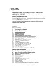
Comparing CPU and CP 443-1 Advanced
In the documentation of the CPU 317-2 PN/DP, for example, you can see the
influence as shown in the following graphic. Lines 1 and 2 show this influence
when the CPU interface is used for PROFINET CBA.
The additional line in the graphic shows the influence when you use the
PROFINET CBA interface of a CP 443-1 Advanced (here: 6GK7 443-1EX40) in an
S7-400 station.
It can be seen that in contrast to operation over a CPU network attachment, the
OB1 cycle remains practically uninfluenced by the CBA communication if
PROFINET CBA is operated over a CP 443-1 Advanced.
Extension of the
cycle time in ms
6
1
5
2
4
3
2
1
0
0
3
20
40
60
80
100
120
140
160
180
200
Number of PROFINET CBA interconnections
Legend:
B−38
1
OB1 cycle with 32 PROFINET CBA partners and network attachment on the
CPU 317-2 PN/DP.
2
OB1 cycle with 5 PROFINET CBA partners and network attachment on the
CPU 317-2 PN/DP.
3
OB1 cycle with an S7-400 station with CPU 416-2 and with network attachment on the
CP 443-1 Advanced (the number of PROFINET CBA partners has no influence).
CP 443-1 Advanced for Industrial Ethernet / Manual Part B
Release 05/2009
C79000-G8976-C224−04
5
5.6.3
Performance Data / Operation
Reaction times
Definition
The reaction time is the time from recognizing an input signal until the associated
output signal changes.
Influences
The actual reaction time is subject to certain fluctuations. The achievable reaction
times for PROFINET CBA communication depend on the following factors:
S
Type of interconnection (cyclic or acyclic) and the transmission frequency or
scanning frequency;
S
The size of the configuration on the component interface (size of the interface
DB for PROFINET CBA);
S
CPU cycle time and CPU type;
S
Parallel operations with other types of communication types such as
PROFINET IO or with services such as online monitoring.
As a result, the reaction times for cyclic PROFINET CBA interconnections may
exceed the configured value for the transfer frequency. You should therefore check
the reaction time that can be achieved during commissioning and, if necessary,
change the project engineering.
Measurements in a sample configuration
Measurements were made to help you to estimate the influence of the configured
transfer frequency and the configuration (interface DB) with cyclic PROFINET CBA
interconnections.
These measured results relate to a certain sample configuration. Two S7-400
stations each with a CP 443-1 Advanced were used (here: 6GK7 443-1EX40).
FB90 was used in the user program (FB90 has better time characteristics than
FB88).
S7-400 station 1
S7-400 station 2
CPU 416-2
CPU 416-2
CP 443-1 advanced
CP 443-1 advanced
Measurement principle:
CP 443-1 Advanced for Industrial Ethernet / Manual Part B
Release 05/2009
C79000-G8976-C224−04
B−39
5
Performance Data / Operation
Output data is generated by station 1 and interconnected as input data with station
2. The input data is mirrored there and transferred over interconnections back to
station 1 where it is evaluated and forwarded etc. The time required for the
individual transfer and evaluation cycle is measured in station 1. This corresponds
to approximately twice the reaction time according to the definition above.
The CPU cycle time (cycle time of OB1) for this measurement is 6 ms.
Note: With shorter cycle times, the reaction times are further reduced and with
longer cycle times they are correspondingly extended.
Measurement results
From the following diagram, you can see the average values for the reaction time
of the cyclic interconnections depending on the size of the interface DB.
Average
reaction
time in ms
70
60
1
50
2
40
3
30
20
10
0
0
480
960
1440
1920
2400
2880
Size of the interface DB in bytes
Legend
The transfer frequency set in the parameters in SIMATIC
iMap is as follows for the recorded lines:
1
50 ms
2 20 ms
3
10 ms
Evaluation
From the diagram, you can see that the transfer frequencies configured at 10 ms
or 20 ms in the sample configured are not achieved. On the other hand, at a
configured transfer frequency of 50 ms, a corresponding reaction time of 50 ms
with 2400 bytes is kept to.
B−40
CP 443-1 Advanced for Industrial Ethernet / Manual Part B
Release 05/2009
C79000-G8976-C224−04
5
Performance Data / Operation
Note
The values of the utilization parameters displayed by SIMATIC iMap as of V2.0
with the “Edit / Check utilization“ function relate to the data exchange as far as the
CP. They do not apply to data access from the user program.
5.7
Characteristic data for FTP mode
TCP connections for FTP
FTP actions are transferred from the CP over TCP connections. Depending on the
mode, the following characteristic data apply:
S
FTP in client mode:
You can configure a maximum of 20 FTP connections. Up to 2 TCP
connections are occupied per configured FTP connection.
S
FTP in server mode:
You can operate a maximum of 10 FTP sessions at the same time. Up to 2
TCP connections are occupied per FTP session (1 control connection and 1
data connection).
FB 40 for FTP client mode
For communication via a TCP connection configured with the “Use FTP protocol”
option, use the FTP block FB40.
The block execution time in FTP depends on the reaction times of the partner and
the length of the user data; a general statement about the times is therefore not
possible.
The functions used in the predecessor modules for FTP transfer (FC40...FC44)
can continue to be used.
5.8
Characteristic data of TCP connections for HTTP
Each HTTP session occupies up to 4 TCP connections as soon as you use one or
more Web browsers to display data or files of the CP.
CP 443-1 Advanced for Industrial Ethernet / Manual Part B
Release 05/2009
C79000-G8976-C224−04
B−41
5
Performance Data / Operation
5.9
Characteristic data for the use of Java applets
To transfer larger amounts of data efficiently from the S7BeansAPI using Java
applets and the Java bean “S7Variable“, you can make use of arrays.
Maximum array size
The maximum array size for the CP 443-1 Advanced
S
is 400 bytes when writing data to the CPU and
S
400 bytes when reading data from the CPU.
Note
Please note that the maximum block size in bytes is specified here and that the
maximum number of array elements is decided by the byte size of the array basic
data type.
Example
The CP 443-1 Advanced can transfer a maximum of 100 array elements of the
type DWORD or REAL with a read job since each element of the type DWORD or
REAL occupies four bytes.
B−42
CP 443-1 Advanced for Industrial Ethernet / Manual Part B
Release 05/2009
C79000-G8976-C224−04
5
5.10
5.10.1
Performance Data / Operation
Memory organization in the CP 443-1 Advanced
Memory distribution
The data areas of the CP 443-1 Advanced are organized as follows:
Permanent
data
Factory-set MAC
address
C-PLUG
Retentive parameters
Configured MAC address
IP address and IP parameters
Flash file system
LAN settings
Interconnection information
for PROFINET CBA
RAM area
CPU data
SNMP Variables (modifiable)
Volatile RAM file
system (/ram)
Configuration data
Data maintained on the S7-400
CPU.
Meaning of the memory areas
S
Flash area in the C-PLUG (non-volatile memory):
The flash area allows data to be stored and retained if there is a power down.
Since the number of times it is possible to write to this area is restricted, you
should avoid repetitive write operations to this area, when such operations are
necessary, write to RAM.
Notice
The flash area of the file system allows a limited number of write cycles
(approximately 100 000). You should therefore avoid writing data cyclically.
If you are writing temporary data often, you should use the RAM file system
located in the subfolder /ram. The files of the RAM file system (/ram) are lost if
there is power down.
CP 443-1 Advanced for Industrial Ethernet / Manual Part B
Release 05/2009
C79000-G8976-C224−04
B−43
5
Performance Data / Operation
S
RAM area (/ram volatile memory):
In contrast to the flash area, the RAM can be written to and read from any
number of times. The data in the RAM are retained as long as the CP is
supplied with power.
The RAM is intended to store data that change during operation and need to be
recorded (data recording services). The RAM is also suitable for temporary
storage.
The RAM is located in the file system below the “/ram“ folder. All files and
folders below this folder are lost when there is a power down.
Please remember the following restrictions:
Table 5-9
Characteristic
Explanation / values
File Names
The length of file names is limited to 64 characters for the file name
itself and up to 256 characters for the path.
It is possible to make the file name case-sensitive in the “Options” tab
of the CP properties dialog.
File Size
The file size is limited to a maximum of 8 MB.
Memory Area for the File System
− Flash area (non-volatile memory)
30 MB
− RAM area (volatile memory)
30 MB
5.11
Characteristic data of the integrated 4-port switch
Learning addresses / deleting addresses (aging time)
The switch integrated in the CP reads the source addresses included in the data
packets. The switch therefore learns the addresses of the end devices connected
via a port.
If the switch receives a data packet, it directs this packet only to the port via which
the appropriate DTE can be obtained.
The switch monitors the age of the learned addresses. Addresses that exceed the
“aging time“ are deleted. The aging time is 5 minutes.
B−44
CP 443-1 Advanced for Industrial Ethernet / Manual Part B
Release 05/2009
C79000-G8976-C224−04
5
Performance Data / Operation
Ports can be deactivated individually
The ports of the switch integrated in the CP can be deactivated individually in
STEP 7 / HW Config. This can, for example, be used for service purposes.
To do this, open the properties dialog of the relevant port and select the “disabled”
setting under “Options > Transfer medium / duplex”.
The port is turned off completely when it is deactivated. The corresponding LED on
the device (for example P1) is then turned off.
CP 443-1 Advanced for Industrial Ethernet / Manual Part B
Release 05/2009
C79000-G8976-C224−04
B−45
6
Using the CP for PROFINET CBA
6
Using the CP for PROFINET CBA
To be able to use the CP 443-1 Advanced with PROFINET CBA, you create your
user program with STEP 7 and configure the S7-400 station.
You then configure the interconnections between the PROFINET CBA components
with SIMATIC iMap.
Notice
Operation under PROFINET CBA, is supported only via the PROFINET interface.
The following information on configuration therefore relates only to the
configuration of the ERTEC Ethernet interface.
6.1
CBA interface in the user program with FB90 or FB88
PN_InOut_Fast (FB90) / PN_InOut (FB88) and interface DB
The interface to the user program is the interface DB for PROFINET CBA. The
PN_IO_X (FB90) and PN_InOut (FB88) blocks are responsible for transferring
data from the interface DB to the CP and from the CP to the interface DB.
The activities of the function blocks FB90 and FB88 on the interface to the user
program are practically the same. The following points apply:
S
The interface parameters are identical;
S
For FB90, there are several additional codes in the STATUS parameter;
S
There are differences in the configuration limits of the interface DB (see Table
5-8).
Please note the documentation of the function blocks in the online help of STEP 7
or in the manual /10/.
Notice
Only one of the two block types FB88 or FB90 can be used in the user program of
an S7-400 station. Componentization is rejected if both block types are used at the
same time.
B−46
CP 443-1 Advanced for Industrial Ethernet / Manual Part B
Release 05/2009
C79000-G8976-C224−04
6
6.2
Using the CP for PROFINET CBA
Preparing for configuration with STEP 7
During configuration, remember the following requirements for subsequent use
with PROFINET CBA:
S
Configure the modules for the S7-400 station in HW Config
You can assign the option “Use this module for PROFINET CBA to one (and
one only) CP 443-1 Advanced in an S7-400 (in the “PROFINET” tab)
In multicomputing, the PROFINET CBA function is handled by the CPU that
you assigned to the CP in the “Addresses” tab.
S
Configuring the ERTEC Ethernet interface
If you use the S7-400 station as a standard component, you will need to make
the following settings when you later configure the ERTEC Ethernet interface:
− Disable the “Set MAC address / use ISO protocol” option;
Notice
ISO transport connections and S7 connections using the ISO protocol cannot be
operated when using the S7-400 station as a PROFINET CBA standard
component!
For more detailed information on adopting the configuration data in the SIMATIC
iMap engineering tool, refer to the documentation on SIMATIC iMap /8/.
CP 443-1 Advanced for Industrial Ethernet / Manual Part B
Release 05/2009
C79000-G8976-C224−04
B−47
6
Using the CP for PROFINET CBA
6.3
PROFINET CBA configuration with SIMATIC iMap
Function in the PROFINET CBA environment
The CP 443-1 Advanced is a PROFINET CBA-compliant device. An S7-400
station equipped with this CP can be interconnected in SIMATIC iMap as a
PROFINET CBA component.
The project engineering of the interconnections between the PROFINET CBA
components is done in the plant view of SIMATIC iMap.
Representation in SIMATIC iMap
S
Network view in SIMATIC iMap
The following graphic shows the network view of SIMATIC iMAP and illustrates
how a CP 443-1 Advanced in an S7-400 station establishes a connection
between DP slaves on PROFIBUS DP and the S7-400 station on Industrial
Ethernet over an IE/PB Link.
Ind. Ethernet
S7-400 stations with
CP 443-1 Advanced
B−48
PROFIBUS-DP
CP 443-1 Advanced for Industrial Ethernet / Manual Part B
Release 05/2009
C79000-G8976-C224−04
6
S
Using the CP for PROFINET CBA
Plant view in SIMATIC iMap
In the plant view, the interconnection of input and outputs over the
CP 443-1 Advanced becomes visible.
Here, you can only see the PROFINET CBA components with their
interconnections to the process inputs and process outputs.
S7-400 stations
with
CP 443-1 Advance
d
Assigning addresses and properties
You assign addresses and properties depending on the component type of the
S7-400 station as follows:
S
S7-400 station as singleton component
Addresses and properties can only be changed in STEP 7.
S
S7-400 station as standard component
Addresses and properties can only be changed in SIMATIC iMap.
CP 443-1 Advanced for Industrial Ethernet / Manual Part B
Release 05/2009
C79000-G8976-C224−04
B−49
6
Using the CP for PROFINET CBA
Downloading configuration data
When using PROFINET CBA, downloading configuration data depends on the
component type of the S7-400 station, as follows:
S
S7-400 station as singleton component
Step
1.
Explanation / meaning
S Downloading with STEP 7
Download the user program and configuration data to the S7-400 station with
STEP 7.
2.
S
Downloading the interconnection information of the process inputs and process
outputs to the PROFINET CBA components over the Ethernet port with SIMATIC
iMap.
S7-400 station as standard component
Step
1.
Explanation / meaning
S Downloading with SIMATIC iMap
Download the user program and configuration data to the S7-400 station with
SIMATIC iMap.
2.
Downloading the interconnection information of the process inputs and process
outputs to the PROFINET CBA components over the Ethernet port with SIMATIC
iMap.
Note
When you reload user program blocks, data consistency is only guaranteed if the
CPU is first changed to STOP.
Caution
If problems occur while downloading interconnections from SIMATIC iMap, for
example power down on the target station, it is not always possible to download
the interconnections again when the power returns.
If this error occurs, SIMATIC iMap reports the station as being unreachable.
Remedy:
Put the CP 443-1 Advanced through a STOP/RUN cycle using the PG command.
This returns the target station to an operable status and allows the
interconnections to be loaded again from SIMATIC iMap.
B−50
CP 443-1 Advanced for Industrial Ethernet / Manual Part B
Release 05/2009
C79000-G8976-C224−04
6
Using the CP for PROFINET CBA
Device diagnostics in SIMATIC iMap
In online view of SIMATIC iMap, you can use diagnostic functions and, for
example, read out device and functional information.
Note
For more detailed information on adopting the configuration from STEP 7 and use
with PROFINET CBA and the SIMATIC iMap engineering tool, refer to the
documentation on SIMATIC iMap /8/.
6.4
Using PROFINET CBA communication and standard
communication at the same time
Notice
The information in this section applies only if a singleton component was created
from the S7-400 station. With a standard component, the connection information
configured in STEP 7 is lost.
Overview
Parallel operation of PROFINET CBA communication and standard communication
using the services S7 communication and S5-compatible communication is
possible with the CP.
This mode is important for your application when, for example, you want to
implement communication between existing “conventional” SIMATIC devices and
PROFINET CBA devices in an existing system.
The special feature is that the configuration of the communication for PROFINET
CBA devices is only possible in SIMATIC iMap. Communication with conventional
devices, on the other hand, requires that the connections are configured in
STEP 7.
Recommended procedure
Here, we would like to give you a few tips and recommendations.
For communication between a PROFINET CBA device and a conventional device,
use S7 or ISP transport, TCP or ISO-on-TCP connections.
CP 443-1 Advanced for Industrial Ethernet / Manual Part B
Release 05/2009
C79000-G8976-C224−04
B−51
6
Using the CP for PROFINET CBA
Configure the S7 and TCP connections in STEP 7 as follows:
S
for S7 communication
− PROFINET CBA device:
single-ended, passive (partner unspecified)
(no configuration is necessary if the device involved in S7 communication is
operated simply as a server).
− conventional device: single-ended, active
S
for S5-compatible communication (ISO transport / TCP / ISO-on-TCP
connections)
− PROFINET CBA device and specified, passive
− conventional device: unspecified, active
This achieves the following:
S
You can specify the connection after for the conventional devices at any time
with STEP 7.
S
You can use the PROFINET devices in SIMATIC iMap (in other words connect
them) without having to change the connection configuration again in STEP 7;
the devices are always ready to send and receive on the configured
connections (connection is established by the active partner).
For the PROFINET CBA device, this means the following procedure:
B−52
Step
Explanation / meaning
1.
First configure unspecified connections in STEP 7 (only with TCP − see above).
2.
Create suitable user programs in STEP 7 to handle communication with the
conventional devices.
3.
Then generate the PROFINET CBA components in STEP 7 and enter these in
the SIMATIC iMap library.
4.
Interconnect the PROFINET CBA component in SIMATIC iMap.
5.
Downloading the user program and configuration data to the S7-400 station with
STEP 7.
6.
Downloading the interconnection information of the process inputs and process
outputs to the PROFINET CBA components over the Ethernet port with SIMATIC
iMap.
CP 443-1 Advanced for Industrial Ethernet / Manual Part B
Release 05/2009
C79000-G8976-C224−04
7
7
7.1
The CP as Web server
The CP as Web server
HTML process control with IT functions
The CP provides you with the function of a Web server for access using a Web
browser.
IT functions
When shipped, the file system of the CP 443-1 Advanced contains S7 beans and
further information. The CP also provides HTML pages for Web diagnostics.
HTML pages are used to indicate and display information in a Web browser.
These, for example, contain diagnostic information.
With the following address, you have access to Web diagnostics:
http:\\<IP address of the CP>
When supplied, diagnostic buffer entries shown on diagnostic pages are always in
English. How to load other languages on the CP is described in the following
sections.
For detailed information on Web diagnostics, refer to the general Part A of this
manual.
Please note the following special features when operating IT functions:
Note
The data exchange for productive communication (S7 connections +
SEND/RECEIVE connections + PROFINET IO) always has a higher priority than
data exchange with the Web browser. This can lead to delays in the HTML
process control in the Web browser.
Enabling the Web server function
If you want to use the CP for IP communication with HTTP, you will need to
activate port 80 of the CP in the configuration:
Select the option “Activate Web server” under “IP access protection” in the
properties dialog of the CP.
The Web server function is enabled as default.
CP 443-1 Advanced for Industrial Ethernet / Manual Part B
Release 05/2009
C79000-G8976-C224−04
B−53
7
The CP as Web server
Web browser
To access the HTML pages on the CP, you require a Web browser. The following
Web browsers are suitable for communication with the CP (other browsers also
possible):
S
Internet Explorer (recommended version: 6.0 or higher)
S
Opera (recommended version: 9.2 or higher)
S
Firefox (recommended version: 2.0 or higher)
These Web browsers support all the requirements necessary for the
implementation of the IT functions (Java reference implementation − Java
Development Kit) 1.1.x is supported) in conjunction with the CP.
7.2
Web diagnostics − Language setting of the text file for
diagnostic buffer events
Diagnostic buffer events can be output in Web diagnostics. The necessary text file
is available in English on the CP when it ships.
You can change the language of the diagnostic messages by writing the text file
from your STEP 7 installation to the file system of the CP by transferring it with
FTP. As soon as a text file is transferred to the file system of the CP as described
below, the CP uses this file instead of the default text file as shipped.
S
If STEP*7 is installed, you will find the text files for specific languages in:
..\Program files\Common files\Siemens\s7wmed\data
The files are stored there in the form “s7wmeldx.edb”,
(where x = {a,b,c,d,e,j}
a = German; b = English; c = French; d = Spanish; e = Italian; j = Japanese)
To transfer the file with FTP, change the name of the required file to
“s7wmeld.edb”.
S
The file must be transferred by FTP in binary mode and stored in the file
system of the CP in:
/config/s7wmeld.edb (case-sensitive)
Note
You can also use the method described here to update the text file.
B−54
CP 443-1 Advanced for Industrial Ethernet / Manual Part B
Release 05/2009
C79000-G8976-C224−04
8
8
Compatibility with Predecessor Products
Compatibility with Predecessor Products
The short names used below to identify the modules (for example “GX20” or
“EX41”) correspond to the last four characters of the mid section of the order
number.
8.1
Enhanced functions
New: Enhanced functions compared with the CP 443−1 GX20 V2.0
The CP 443−1 (6GK7 443−1GX20−0XE0 with firmware version 2.1) supports all
functions of the predecessor module (6GK7 443−1EX20−0XE0 with firmware
version V2.0 and 1.0).
The following features are new and can be used when configuring with STEP 7 as
of version 5.5:
S
Shared device in PROFINET IO (can be configured as of CPU version V5.3)
Enhanced functions compared with the CP 443−1 EX41
The CP 443-1 Advanced (6GK7 443-1GX20-0XE0) supports all functions of the
previous module (6GK7 443-1EX41-0XE0) with the restrictions listed further below.
The following features are new and can be used when configuring with STEP 7 as
of version 5.4 SP4:
S
Gigabit interface
S
IRT communication with PROFINET IO
S
Support of H connections for the S7–400H (fault-tolerant system)
S
Prioritized startup
S
E-mail with Authentication, in other words, configurable access control
S
New function block for FTP client mode (optional)
S
Expanded Web diagnostics
S
SEND/RECV connections in SPEED SEND/RECV mode
S
UDP buffering can be disabled
S
Memory area for RAM file system expanded to 30 Mbytes
S
Support of alarms for operation of an iPAR server
CP 443-1 Advanced for Industrial Ethernet / Manual Part B
Release 05/2009
C79000-G8976-C224−04
B−55
8
Compatibility with Predecessor Products
S
PROFINET CBA:
The following feature can be used when configuring as of service pack 3 for
SIMATIC iMap STEP 7 Add-on V2.0: PROFINET CBA communication parallel
to communication via the ISO protocol (only for singleton components).
S
Clear / reset
If the CP is configured as a PROFINET IO controller, an you run a clear/reset
on the CPU, the CP memory is also reset.
8.2
Changes
Note the following changes compared with the predecessor modules:
S
The mode selector is no longer present.
S
The data length in CBA for cyclic interconnections of arrays and structures is
limited to a maximum of 250 bytes.
S
SRAM file system no longer exists.
S
ACL-LOG file in the file system no longer exists, LOG data can be viewed via
HTTP server.
Notice
The CP 443-1 EX20 and CP 443-1 Advanced GX20 modules are not
interchangeable as replacement modules (see below). You can, however, upgrade
the EX20 with a GX20 if you change the configuration.
B−56
CP 443-1 Advanced for Industrial Ethernet / Manual Part B
Release 05/2009
C79000-G8976-C224−04
8
8.3
Compatibility with Predecessor Products
Replacing older modules: spares / upgrading
Distinction
When replacing existing modules with the module described here, the following
variants must be distinguished:
S
Use as a replacement:
The situation described here is when an existing module can be replaced by a
new module by removing and inserting it with no change to the configuration.
When removing and inserting the module, remember the instructions in Section
3.1, in particular, if you are using the CP as a PROFINET IO controller.
S
Upgrading (functionally compatible module replacement)
The situation in this case is when the module described here can be used
instead of an older module as long as adaptations are made in the
configuration. The CP used previously is replaced by the new CP in the
configuration.
Unless stated otherwise, the range of functions of the older module continues to be
supported in both cases.
You can also upgrade modules listed under “use as a replacement”. This becomes
necessary when you want to use new features that were not available on the
previously used module.
Use as a replacement:
The CP 443-1 Advanced with order number 6GK7 443-1GX20-0XE0 (firmware
version 2.0) described here can be used as a replacement for the following
predecessor products:
S
CP 443−1 Advanced (6GK7 443−1EX41−0XE0) with CPUs as of firmware
version 4.1
S
CP 443−1 IT (6GK7 443−1GX11−0XE0) with CPUs as of firmware version 4.1
CPUs with firmware version 4.0 must be upgraded to V4.1.
If a replacement is required with CPUs with a firmware version less than V4.0,
6GK7 443−1GX11−0XE0 or 6GK7 443−1EX41−0XE0 must still be ordered.
You will find more information on the listed predecessor modules listed in the rest
of this chapter:
CP 443-1 Advanced for Industrial Ethernet / Manual Part B
Release 05/2009
C79000-G8976-C224−04
B−57
8
Compatibility with Predecessor Products
Upgrading
The following predecessor products can be upgraded to the CP 443−1 Advanced
(6GK7 443−1GX20−0XE0) described here:
S
CP 443-1 Advanced (6GK7 443-1EX40-0XE0)
S
See modules in “use as a replacement”
Module replacement with the CP 443-1 Advanced (EX40 / EX41)
When replacing an older module (EX40 or EX41) with the new module (GX20),
please keep to the steps outlined below:
Step 1: Replacing the CP
Explanation / meaning
1.
Remove the module you want to replace from the rack.
2.
Insert the C-PLUG from the replaced module in the new module.
3.
Insert the new module in the rack with the C-PLUG taken from the removed
module.
4.
Note the following and, if using the EX40, continue with step 2 as described
further below.
Note
You do not need to cycle the power off and on.
Remember the following restrictions:
S If OB83 is not loaded, the CPU changes to STOP.
S In PROFINET IO mode, the power supply must be cycled (off−on).
Notice
The C-PLUG taken from the removed module has the ID “EX40“ or “EX41“; this
has no effect on operation of the new CP (GX20).
If, however, you do not want to keep this ID, you must either user the C-PLUG
supplied with the new CP or reformat the C-PLUG of the old module. You must
then, however, supply the CP with an IP address again (node initialization).
B−58
CP 443-1 Advanced for Industrial Ethernet / Manual Part B
Release 05/2009
C79000-G8976-C224−04
8
Compatibility with Predecessor Products
Step 2: Adapting the configuration (upgrading an EX40)
Explanation / meaning
1.
In STEP 7 / HW Config, replace the previously configured CP with the new
module from the hardware catalog.
2.
As soon as you drag the new module from the catalog to the module to be
replaced in HW Config, the configured connections and data are adopted.
3.
If necessary, extend the configuration to meet your requirements, for example in
the Properties dialog of the Ethernet subnet.
4.
Save and compile the project.
5.
Download the configuration data to the target system again.
Notice
If you have been using an EX40 with PROFINET communication, the EX40 can
only be replaced by a GX20 if you have a CPU as of firmware version 5.1 (see
also Section 2.2). In this case, you will need to adapt the configuration.
Replacing other module types (GX11)
Other older modules (GX11) can be replaced in different ways depending on the
way data is stored:
S
In this case, it is not necessary to adapt or download the configuration data; all
characteristics of the new module are the same as those of the replaced
module.
This variant is possible only when the originally used CP was configured with
data storage on the CPU (“Module replacement without PG” option).
Step
S
Procedure
1.
Remove the module you want to replace from the rack.
2.
Insert the new module in the rack.
Data stored on the CP: Module replacement and download
The module needs to be supplied with the existing or adapted configuration
data.
These variants are necessary when the originally used CP was configured with
data storage on the CP, in other words, without the “Module replacement
without PG” option.
CP 443-1 Advanced for Industrial Ethernet / Manual Part B
Release 05/2009
C79000-G8976-C224−04
B−59
8
Compatibility with Predecessor Products
− Variant A: Adapting the STEP 7 project (preferred solution)
If you adopt the configuration data unchanged and therefore leave the “Data
storage on CP“ option, you do not make use of the option for protecting data
from a power down as provided by the new CP. We therefore recommend
that you adapt the existing configuration to the new CP type whenever
possible:
Explanation / meaning
1.
Replace the old module with the new module in the rack.
2.
In STEP 7 / HW Config, replace the previously configured CP with the new
module from the hardware catalog.
As soon as you drag the new module from the catalog to the module to be
replaced in HW Config, the configured connections and data are adopted.
The mode is automatically configured as “Data storage on the CPU“.
3.
Save and compile the project.
4.
Download the configuration data to the target system again.
− Variant B: STEP 7 project unchanged
If you do not want to use any of the new features, you can replace the
module as follows without any additional configuration work:
Step
Procedure
1.
Remove the module you want to replace from the rack.
2.
Insert the new module in the rack.
3.
Download the configuration data from the project on the PG/PC to the
new module.
Result:
After downloading the configuration, the CP changes to RUN.
From the following table 8-1, you can see which of the options described above
exist for the available module types. Refer to the description above for the possible
procedures.
B−60
CP 443-1 Advanced for Industrial Ethernet / Manual Part B
Release 05/2009
C79000-G8976-C224−04
8
Table 8-1
Compatibility with Predecessor Products
Response of the module following module replacement
Previously used module
6GK7 443-1GX11-0XE0
Data storage
(configurable)
CP
CPU
X
X
Response / notes
Replacement with spare is possible; procedure
depending on selected data storage strategy in the
previous module.
S Retentiveness of data storage on the CP:
IP address is retained following a power cycle;
this means that downloading and diagnostics is
possible using the existing IP address.
S The IT functionality in the new CP corresponds
to the range of functions of the previous
module.
If you want to use new IT functions of the
GX20, you will have to change the configuration
with the appropriate STEP 7 version.
CP 443-1 Advanced for Industrial Ethernet / Manual Part B
Release 05/2009
C79000-G8976-C224−04
B−61
9
Further Notes on Operation
9
9.1
Further Notes on Operation
Memory reset / reset to factory defaults
The CP has a two-level function available for resetting memory:
S
Clear / reset
S
Resetting to factory settings
Notice
The functions for resetting and resetting to factory defaults described here do not
change the configuration data on the CPU! Only the data kept on the CP (C-PLUG
and RAM) is deleted.
If you subsequently upload the configuration data from the CPU to a PG you will
always object the configuration data that were previously on the CP (with
parameters, connections, IP address).
Notice
If you clear/reset a CPU as of version 5.2, the CP memory is also reset if you are
using PROFINET IO.
How to use the functions
You can start the memory reset functions in STEP 7. The CP must be in STOP. If
you are using PROFINET IO mode, the CPU must also be in STOP.
S
Clear / reset
In STEP 7/HW Config with PLC
"
Clear/Reset
or
In STEP 7 / NCM Diagnostics with Operating Mode
S
"
Clear/Reset Module
Resetting to factory settings
In STEP 7 / SIMATIC Manager über den Menübefehl Zielsystem "
Ethernet−Teilnehmer bearbeiten... " CP auswählen " “OK” " Rücksetzen auf
Werkseinstellungen
or
In STEP 7 / NCM Diagnostics with Operating Mode
Defaults
B−62
"
Reset to Factory
CP 443-1 Advanced for Industrial Ethernet / Manual Part B
Release 05/2009
C79000-G8976-C224−04
9
Further Notes on Operation
Clear/reset module − Effects
After resetting memory, the CP retains the configured MAC address, the IP
address and the retentive parameters (for information on the retentive parameters,
refer to Section 3.2). The CP is therefore immediately ready for downloads using
the IP address.
The configuration data is retained on the CPU.
The CPU in the S7 station does not recognize that the CP memory was reset. The
CP changes to the “stopped with error” state (see Chapter 4). The configuration
data must then be reloaded. You can also initiate this loading by cycling power
(OFF/ON).
This has the following overall effect:
Permanent
data
Factory set MAC
address
C-PLUG
Retentive parameters
Flash file system
RAM area
Volatile RAM file
system (/ram)
Deleted data area
CPU data
Configuration data
CP 443-1 Advanced for Industrial Ethernet / Manual Part B
Release 05/2009
C79000-G8976-C224−04
Data maintained on the S7-400
CPU.
B−63
9
Further Notes on Operation
Rest to factory defaults − Effects
After resetting to factory defaults, the CP always retains the factory set MAC
address (as supplied).
The IP address and the configuration data in the CP RAM are deleted. The
configuration data is retained on the CPU.
The data in the file system of the C-PLUG (flash area) is retained, the retentive
parameters are deleted.
This has the following overall effect:
Permanent
data
Factory set MAC
address
C-PLUG
Retentive parameters
Flash file system
Deleted data areas
RAM area
CPU data
Volatile RAM file
system (/ram)
Configuration data
Data maintained on the S7-400
CPU.
Note
Remember that the interconnection information for PROFINET CBA belongs to the
retentively stored parameters on the C-PLUG and is therefore deleted by this
action.
B−64
CP 443-1 Advanced for Industrial Ethernet / Manual Part B
Release 05/2009
C79000-G8976-C224−04
9
9.2
9.2.1
Further Notes on Operation
Network settings with Fast Ethernet / gigabit Ethernet
Fast Ethernet with the PROFINET and gigabit interface
The common transmission characteristics of the two interfaces are described
below. For information on the transmission speed 1 Gbps of the gigabit interface,
see Section 9.2.2.
The configuration of the network settings “Transmission medium / duplex” is made
for both interfaces in the properties dialog of the port of the relevant interface in the
“Options” tab:
Row “X1P1”: Port properties of the gigabit interface
Row “X2P1/2/3/4”: Properties of port 1, 2, 3 or 4 of the PROFINET interface
Automatic setting or individual network settings
As default, the CP is configured for automatic detection (autosensing).
Notice
In normal situations, the basic setting ensures trouble-free communication. You
should only change these in exceptional situations.
If you create a manual configuration for the CP and disable the Autonegotiation
option, the automatic negotiation of the network settings (Autonegotiation) is no
longer effective.
With the gigabit interface, simply creating a manual configuration means that
autonegotiation is no longer effective.
If, on the other hand, the communication partner works with autonegotiation, no
communication will be established.
Autocrossing mechanism
With the autocrossing mechanism integrated in the switch, it is possible to use a
standard cable to connect the PC/PG. A crossover cable is not necessary.
CP 443-1 Advanced for Industrial Ethernet / Manual Part B
Release 05/2009
C79000-G8976-C224−04
B−65
9
Further Notes on Operation
Notice
Manual configuration
If you have set a port to manual configuration and select the “Disable
autonegotiation/autocrossover” option, the autocrossing mechanism is also
disabled for this port. The port then behaves like the interface of a switch. In this
case, the following applies:
S Connecting an end device
To connect an end device that does not have the autocrossing mechanism (for
example CP 443-1 with order number 6GK7 443-1EX11-0XE0), you must not
use a crossover cable.
S Connecting to a switch
To connect a switch, that does not support the autocrossing mechanism, use a
crossover cable.
STEP 7 / NCM Diagnostics and Web diagnostics display the network setting
Diagnostics of the port settings for the CP described here is possible using the
entries in the diagnostic buffer over SNMP, NCM diagnostics, and the LED
displays.
You will find information on the currently used network settings in STEP 7 as
follows:
S
In NCM Diagnostics under the diagnostic object “Industrial Ethernet” in the
“Network Attachment” group box;
S
In HW Config with the menu command “PLC > Module Information”;
S
In WEB diagnostics.
Diagnostic data of the gigabit interface are available only with Web diagnostics.
Further notes:
S
10/100 Mbps network components without “Autonegotiation”
If you use 10/100 Mbps network components that do not support
“Autonegotiation”, it is possible that you will have to set the mode manually.
S
Forcing a specific mode instead of “Automatic settings”
If your application requires a specific mode instead of the automatic settings,
you will need to match up the partner devices.
S
No reaction to Autonegotiation query with manual configuration
Remember that if you configure the CP manually and the “Autonegotiation”
option is disabled, it will not react to an autonegotiation query! As a result, a
connected partner will not be able to set the required mode and communication
will not be ideal.
B−66
CP 443-1 Advanced for Industrial Ethernet / Manual Part B
Release 05/2009
C79000-G8976-C224−04
9
Further Notes on Operation
Example:
If, for example, the CP is set to “100 Mbps − full duplex” and autonegotiation is
disabled, a CP connected as partner will set “100 Mbps − half duplex”. Reason:
Due to the fixed setting, an autonegotiation reply is not possible. Although the
connected partner detects 100 Mbps with autosensing, it remains at half
duplex.
S
Recommendation: Change individual network settings only over MPI.
If you modify the LAN settings in the properties dialog of the CP in the “Options”
tab using the “Transmission medium/Duplex” list box, these changes will be
adopted by the CP and activated when the configuration data is downloaded to
the target system (STEP 7). In some situations, the device may then no longer
be obtainable over Ethernet.
We therefore recommend that you download configuration data to the S7
station over an MPI connection if you change this setting.
If you download the configuration data over the LAN interface, depending on
the selected setting, it is possible that the current download will not be
completed due to the changes to the configuration taking immediate effect and
an inconsistent configuration is reported.
Example:
The download is started initially with the setting TP/ITP at 10 Mbps half duplex.
If the “Individual network setting” is now changed to 100 Mbps full duplex, the
download cannot be completed.
9.2.2
Transmission speed of the gigabit interface
If you want to use transmission speed 1 Gbps, leave the interface set to
“Automatic settings”.
The connection partner must also be configured with “1 Gbps full duplex” or with
“Automatic settings”. If the connection partner does not support gigabit Ethernet,
the data will be transferred at the next lower speed (100 or 10 Mbps).
9.3
9.3.1
PROFINET IO mode with IRT communication
Types of synchronization
Within an IRT domain (Isochronous Real Time), you can use the CP for IRT
communication.
You specify the required synchronization parameters in the properties dialog of the
ERTEC interface (HW Config: Row “X2 (<device name>)”) in the “Synchronization”
tab.
CP 443-1 Advanced for Industrial Ethernet / Manual Part B
Release 05/2009
C79000-G8976-C224−04
B−67
9
Further Notes on Operation
9.4
Media redundancy
You can use the CP in a ring topology with media redundancy. The CP itself can be
redundancy manager.
You create the configuration in STEP 7 in the properties dialog of the PROFINET
interface in the “Media redundancy” tab (HW Config: Row “X2 (<device name>)”).
For more detailed information on configuration, refer to the online help of the
“Media redundancy” tab and in Part A of the manual.
Notice
If you are using IRT communication, no media redundancy is supported.
9.5
Time-of-day synchronization
General rules
The CP supports the two modes explained below for time-of-day synchronization:
S
SIMATIC mode
If the CP receives MMS time-of-day messages, its local time is synchronized
providing the NTP mode was not defined during configuration (MMS =
Manufacturing Message Specification).
The advantage of this mode is that it is generally more accurate than the NTP
mode (guaranteed +− 1 ms). In contrast to the NTP mode, it is not possible to
forward the time of day over routers; in other words, to other subnets.
S
NTP mode (NTP: Network Time Protocol)
In the NTP mode, the CP sends time queries (in the client mode) at regular
intervals to the NTP server in the subnet (LAN). Based on the responses of the
server, the most reliable and most accurate time of day is calculated and the
time synchronized on the station (in all modules with time-of-day functionality).
The advantage of this mode is that the time of day can be synchronized beyond
the boundaries of the subnet. The accuracy depends on the quality of the NTP
server used.
Note
No automatic changeover to daylight saving is defined in NTP. As a result, you
may need to implement this changeover using a program application.
B−68
CP 443-1 Advanced for Industrial Ethernet / Manual Part B
Release 05/2009
C79000-G8976-C224−04
9
Further Notes on Operation
Notice
Note the following regarding time-of-day synchronization in NTP mode:
If the CP recognizes an NTP frame as being “not exact” (example: NTP server is
not externally synchronized), it is not forwarded to the communication bus. If this
problem occurs, none of the NTP servers is displayed as “NTP master” in the
diagnostics; rather all NTP servers are displayed only as being accessible.
Forwarding the time-of-day message
You can configure the direction in which time-of-day messages are forwarded in
STEP 7 / NCM S7 in the properties dialog of the CP as follows.
S
Configuration “from station to LAN”
The CP forwards time frames from the CPU to Industrial Ethernet when the
local CPU is time master (SIMATIC mode only) or when the time of day is
forwarded by a different CP on the K bus.
S
Configuration “from LAN to station”
The CP forwards time frames from the CPU to Industrial Ethernet when one of
the following components is time master:
− In the SIMATIC mode:
− a remote CPU 41x
− a SIMATIC NET time transmitter
− a CP 1430 TF
− an NTP server when using the NTP mode
As default, time-of-day synchronization is not activated for the CP and it does not
therefore forward the time. However, the internal clock of the CP is also
synchronized in this situation when a time-of-day frame is received from the
communication bus or from Industrial Ethernet.
Synchronization using one of the two modes described here must be configured in
STEP 7 in the properties dialog of the CP − “Time-of-Day Synchronization” tab.
For more detailed information on the parameters and options, please refer to the
online help in the properties dialog.
CP 443-1 Advanced for Industrial Ethernet / Manual Part B
Release 05/2009
C79000-G8976-C224−04
B−69
9
Further Notes on Operation
Coordinating forwarding of the time of day with several CPs
If there is more than one CP in a station connected to the same network, only one
of these CPs is allowed to pass on time-of-day messages.
You can therefore made the following settings in the configuration:
S
Automatic
The CP receives the time-of-day message from the LAN or from the station and
forwards it to the station or to the LAN.
If several CPUs are being operated in the station, this automatic setting can
lead to collisions. To avoid this, you can specify the direction of forwarding with
the following options:
S
From station to LAN
S
From LAN to station
Notice
During configuration, there is no consistency check relating to this option when
configuring several CPs
9.6
Recommendations for use with a high communications
load
Overview
When using the CP described here, the points below will help you to avoid
overload situations on your CPU.
In particular when you replace an older CP with the CP described here and are
then confronted with overload problems, you should check your application for the
pitfalls outlined below.
Known problems
B−70
S
The functions for sending and receiving (FC5/FC6, FC50/60 or FC53/63) are
often called cyclically in OB1. This leads to constant communication between
the CPU and CP. As a result, other types of communication such as PG
functions cannot be executed or only very slowly.
S
HMI systems access data of the CPU too often using S7 functions. This slows
down communication generally and can lead to lack of resources on the CPU if
SEND/RECEIVE FCs are called in OB1 cyclically (effect: reduced data
throughput or increased reaction time).
CP 443-1 Advanced for Industrial Ethernet / Manual Part B
Release 05/2009
C79000-G8976-C224−04
9
Further Notes on Operation
Remedy
The recommendations below will help to avoid these situations:
S
Do not call communication blocks cyclically in OB1!
Communication should be called time-controlled in a suitable cyclic-interrupt
OB. The call interval of this OB should be significantly higher than the average
cycle time of OB1.
9.7
S
You should set a minimum cycle time that is higher than the average runtime of
OB1. This frees resources for communication on the CPU. This is, for example,
a remedy for existing applications when communication already takes place
cyclically in OB1.
S
If necessary, reduce the time taken for communication processing on the CPU
by changing the parameters set for “cyclic load due to communication” in the
properties dialog of the CPU.
SNMP agent
SNMP (Simple Network Management Protocol)
The CP supports data queries via SNMP in Version 1. It returns the contents of
certain MIB objects according to the MIB II standard, LLDP MIB and automation
system MIB.
SNMP is a protocol for managing networks. To transmit data, SNMP uses the
connectionless UDP protocol.
The information on the properties of SNMP-compliant devices is entered in MIB
files (MIB = Management Information Base).
Where to find further information
For more detailed information on working with MIB files, refer to the
documentation of the SNMP client you are using (example of an SNMP client:
SNMP OPC Server from SIMATIC NET).
You will find more information on MIB on the following SIMATIC NET Internet
page:
http://support.automation.siemens.com/WW/view/en/15177711
CP 443-1 Advanced for Industrial Ethernet / Manual Part B
Release 05/2009
C79000-G8976-C224−04
B−71
9
Further Notes on Operation
Supported MIB objects
The CP supports the following groups of MIB objects of the MIB II standard, LLDP
MIB and automation system MIB according to RFC1213:
S
System
S
Interfaces
S
IP
S
ICMP
S
TCP
S
UDP
S
SNMP
S
Address Translation (AT)
The other groups of the MIB II standard are not supported:
S
EGP
S
Transmission
The CP also supports the LLDP-MIB according to IEEE 802.1AB and the
PROFINET expansions of the LLDP-MIB (see also IEC 61158-10-6).
Exceptions / restrictions:
S
Write access is permitted only for the following MIB objects of the system
group:
sysContact, sysLocation and sysName;
For all other MIB objects / MIB object groups, only read access is possible for
security reasons.
S
Traps are not supported by the CP.
“Interfaces” MIB group
The “Interfaces” MIB object provides status information on the CP interfaces, with
the following assignment:
This group returns status information about the CP interfaces. The MIB objects of
the ifTable provide the status information of the interfaces. The “ifIndex” object
identifier is assigned to the CP interfaces as follows:
ifIndex
Type of interface
1 *)
Gigabit interface
2−5 (1−4) *)
Port 1−4 (PROFINET interface)
6 (5) *)
Internal CP interface
*) If the gigabit interface is not configured, the value 1 is assigned to the first port of the
PROFINET interface; the next values then move accordingly by one position.
B−72
CP 443-1 Advanced for Industrial Ethernet / Manual Part B
Release 05/2009
C79000-G8976-C224−04
9
Further Notes on Operation
Access permissions using community name
The CP uses the following community names to control the access rights in the
SNMP agent:
Community name *)
Type of access
Read access
public
Read and write access
private
*) Note the use of lower-case letters!
MIB files for your SNMP tools
If you use an SNMP tool, you will find the MIB files relevant to the CP in the
STEP 7 installation in the following folder:
<Drive>\<Installation folder>\Siemens\Step7\S7DATA\snmp\mib
For the Automation System MIB, for example, these are the following files:
automationPS.mib
automationSmi.mib
automationSystem.mib
automationTC.mib
9.8
Possible security gaps on standard IT interfaces /
preventing illegal access
With various SIMATIC NET components, such as switches, a wide range of
parameter assignment and diagnostic functions (for example, Web servers,
network management) are available over open protocols and interfaces. The
possibility of unauthorized misuse of these open protocols and interfaces by third
parties, for example to manipulate data, cannot be entirely excluded.
When using the functions listed above and these open interfaces and protocols (for
example, SNMP, HTTP, Telnet), you should take suitable security measures to
prevent unauthorized access to the components and the network particularly from
within the WAN/Internet.
Notice
We expressly point out that automation networks must be isolated from the rest of
the company network by suitable gateways (for example using tried and tested
firewall systems). We do not accept any liability whatsoever, whatever the legal
justification, for damage resulting from non-adherence to this notice.
CP 443-1 Advanced for Industrial Ethernet / Manual Part B
Release 05/2009
C79000-G8976-C224−04
B−73
9
Further Notes on Operation
If you have questions on the use of firewall systems and IT security, please contact
your local Siemens office or representative. You will find the address in the
SIMATIC catalog IK PI or on the Internet at
http://www.siemens.de/automation/partner
9.9
Points to note about IP configuration
Configured S7 connections cannot be operated if the IP address is assigned
over DHCP
Notice
If you obtain the IP address over DHCP, any S7 connections you may have
configured will not work. Reason: The configured IP address is replaced by the
address obtained over DHCP during operation.
Obtaining the IP address from DHCP is only possible on the ERTEC ports and not
on the gigabit interface.
9.10
Restart after detection of a duplicate IP address in the
network
To save you time-consuming troubleshooting in the network, the CP detects double
addressing in the network. If the CP detects double addressing on the network
(new node with an IP address that has already been assigned), a message is
generated in the diagnostic buffer and the bus fault LED lights up.
To acknowledge the bus fault LED in RUN mode, set the CP to STOP and then
restart it.
When you eliminate the cause by removing the device with the same IP address or
changing its address, you must then restart the CP.
B−74
CP 443-1 Advanced for Industrial Ethernet / Manual Part B
Release 05/2009
C79000-G8976-C224−04
9
9.11
Further Notes on Operation
Prioritized startup in PROFINET IO
Functions
If you use RT or IRT communication, the CP supports the PROFINET functionality
“prioritized startup” for PROFINET IO devices that also support this function. A
maximum of 32 PROFINET IO devices can be configured per IO controller and
startup times with values as low as 0.5 s can be achieved simultaneously for a
maximum of 8 of these devices.
Prioritized startup is used in fast processes in which IO device are changed often,
for example for a fast change of tools on a robot.
The PROFINET “prioritized startup” functionality also achieves a significant
improvement in performance in applications in which a fast startup of the IO
devices is required following “Power on” or after station failure and station return or
when activating IO devices.
Configuration for IO devices
You configure prioritized startup for the IO devices configured in the PROFINET IO
system. To do this, go to STEP 7 / HW Config and select the properties dialogs of
the PROFINET interfaces for the relevant IO devices.
Prioritized startup required fixed port settings.
For more detailed information, refer to /16/ of the SIMATIC PROFINET system
description (see Chapter 13).
Note
After reconfiguring an IO device for prioritized startup, the first startup takes place
in the normal time without being prioritized. All subsequent startups will then be
completed in the reduced time.
Notice
Including an IO device with prioritized startup in a ring topology with media
redundancy serves no practical purpose since the ring is interrupted at each IO
device change.
CP 443-1 Advanced for Industrial Ethernet / Manual Part B
Release 05/2009
C79000-G8976-C224−04
B−75
9
Further Notes on Operation
9.12
9.12.1
Interface in the user program
FC call interface
Change call parameters only after job confirmation
Notice
After the job is triggered, you may only change the call parameters on the FC call
interface of the FCs AG_SEND / AG_LSEND / AG_SSEND or AG_RECV /
AG_LRECV / AG_SRECV again after the FC has confirmed execution of the job
with DONE=1 or with ERROR=1.
If this is ignored, it is possible that the execution of the job will be aborted with an
error and resources could be permanently occupied on the CPU.
9.12.2
Programmed communication connections with FB55
IP_CONFIG
Downloading the configuration using FB55
FB55 allows program-controlled transfer of the configuration data.
Note
If the CP is in PG STOP mode, the configuration is downloaded using FB55; the
CP then changes automatically to RUN.
B−76
CP 443-1 Advanced for Industrial Ethernet / Manual Part B
Release 05/2009
C79000-G8976-C224−04
9
Further Notes on Operation
Points to note / restriction
Notice
S No use of FB55 when using a CP with fault−tolerant S7 connections
If you configure fault−tolerant S7 connections via the CP, you cannot use FB55
for IP configuration of the CP.
You will find more detailed information on special features and use in fault−tolerant
systems in the section “FBs for programmed connections and IP configuration in”
in /10/.
9.12.3
IP access protection with programmed communication
connections
In principle, it is possible to set up communication connections using FB55 by
programming and at the same time by configuring IP access protection. Please
note the following point:
Notice
When configuring specified connections in STEP 7 / NCM S7, the IP addresses of
the partners are entered automatically in the IP-ACL (IP Access Control List).
The IP addresses of partners with unspecified connections (passive end points)
and of partners on programmed communication paths are not entered in the
IP-ACL. This means that communication with unspecified nodes is not possible if
IP access protection is activated.
How to configure IP access protection is described in the general part of this
manual, Part A.
9.12.4
Programmed communications connections − Assigning
parameters to the ports
The CP now supports the following settings when assigning parameters to the
ports in the parameter block for TCP connections and UDP connections:
S
SUB_LOC_PORT parameter
The port can be specified as an option when the connection is established
actively.
S
SUB_REM_PORT parameter
The port can be specified as an option when the connection is established
passively.
CP 443-1 Advanced for Industrial Ethernet / Manual Part B
Release 05/2009
C79000-G8976-C224−04
B−77
9
Further Notes on Operation
9.12.5
Open TCP/IP communication
Use
To allow the user program to exchange data with other TCP/IP-compliant
communication partners, STEP 7 provides a UDT for the connection parameter
assignment and four FBs.
S
UDT 65 “TCON_PAR” with the data structure for connection parameter
assignment
S
FB65 “TCON” for connection establishment
S
FB66 “TDISCON” for connection termination
S
FB63 “TSEND” for sending data
S
FB64 “TRCV” for receiving data
TCP/IP communication is connection-oriented. Data can be transmitted only when
a connection has been established to the communication partner. The CPU can
use several connections to a communications partner at the same time.
The following protocol variants are supported:
S
ISO on TCP according to RFC 1006
Programming
Make the following parameter settings in the connection description (UDT 65):
S
local_tsap_id: Byte 1 = 0xE0 (value mandatory for correct functionality)
S
local_tsap_id: Byte 2 = Rack/slot number
S
remote_tsap_id: Byte 1 = 0xE0 (value mandatory for correct functionality)
S
remote_tsap_id: Byte 2 = Rack/slot number
Note: The TSAPs can be 2−16 bytes long. The first two bytes must be occupied as
described, you can use the other bytes to suit your task.
Notice
Note that the number of dynamically established connections also depends on the
number of configured, statically established connections.
You will obtain appropriate condition codes on the call interface of the FBs.
Please refer to the documentation of the FBs in the online help and in the
documentation for STEP 7. There, you will also find examples of parameter
assignment!
B−78
CP 443-1 Advanced for Industrial Ethernet / Manual Part B
Release 05/2009
C79000-G8976-C224−04
9
9.12.6
Further Notes on Operation
Additions to the FC/FB status condition codes
The following condition codes for the communication FBs/FCs have been added or
modified compared with the information in the online help for STEP 7 V5.4 SP4 or
the manual /10/ Release 03/2008.
FC10 AG_CNTRL
DONE
0
9.13
ERROR STATUS
1
80B2H
Meaning
The configured slot is not occupied.
Gigabit interface − special features in STEP 7
Notice
The STEP 7 functions in the SIMATIC Manager “Display Accessible Nodes” and
“Edit Ethernet Node...” are not supported in the device version of the gigabit
interface described here.
9.14
Attachment to Industrial Ethernet networks
Since the CP forwards frames from and to private and public IP addresses via its
two interfaces, you should not connect the CP to a public network.
9.15
Use of the CP as IP router
The CP can be used to forward IP messages from a local area network to a
higher-level network and vice versa. The CP then controls access permission
according to the configuration.
An extensive network with other IP subnets can then be connected to one of the
Ethernet interfaces. To achieve this, an external router can be configured on this
interface that handles forwarding to nodes that are not directly reachable. In this
case, enter the IP address of this router in “Default Router” for the appropriate
interface in HW Config.
CP 443-1 Advanced for Industrial Ethernet / Manual Part B
Release 05/2009
C79000-G8976-C224−04
B−79
9
Further Notes on Operation
Notice
The use of the CP as a universal router between two extended networks with
further subnets is not supported.
9.16
Ping: Permitted length of ICMP packets
Pings with a packet size of more than 1000 bytes are evaluated as an attack and
filtered by the CP. This response is deliberate and serves to increase robustness in
an industrial environment.
A ping only serves to check reachability. Support of extremely long ICMP packets
is not therefore a necessity.
B−80
CP 443-1 Advanced for Industrial Ethernet / Manual Part B
Release 05/2009
C79000-G8976-C224−04
10 Loading New Firmware
10
Loading New Firmware
Initial situation
You download new firmware to a SIMATIC NET CP using the firmware loader
shipped with STEP 7 / NCM S7.
To download firmware, you require an Industrial Ethernet CP module in the PG/PC
(for example, CP 1613) or a normal Ethernet module with the “SOFTNET IE”
software package.
How to load new firmware
You can load the firmware via both interfaces of the CP.
Always start the download using the current MAC address of the CP!
Notice
Remember that the CPU changes to STOP during downloading of the firmware if
you are using PROFINET IO communication.
Follow the steps below:
1.
Connect the CP module to the PG/PC via a LAN cable.
2.
Start the download on your PG/PC.
The download involves two steps and the following LED patterns are displayed:
S Step 1: Downloading the firmware
INTF, EXTF, BUS1F, BUS2F, MAINT and STOP light up,
RUN flashes.
S Step 2: Activating the firmware
All LEDs light up.
If the download is aborted, RUN and STOP flash alternately.
3.
After the firmware download, the CP goes through a warm restart.
What to do if a download is interrupted
Disturbances or collisions on the network can lead to packets being lost. In such
cases, this can lead to an interruption of the firmware download. The firmware
loader then signals a timeout or negative response from the module being loaded.
En entry is made in the diagnostic buffer. The CP works with the firmware that
existed before the aborted download.
Repeat the download using the active MAC address after the CP has started up
again.
CP 443-1 Advanced for Industrial Ethernet / Manual Part B
Release 05/2009
C79000-G8976-C224−04
B−81
10 Loading New Firmware
If you cannot start the download again following an aborted attempt, you should
turn off the entire rack and turn it on again. You can then restart the firmware
download.
B−82
CP 443-1 Advanced for Industrial Ethernet / Manual Part B
Release 05/2009
C79000-G8976-C224−04
11
11
Technical Specifications
Technical Specifications
Table 11-1 Technical specifications
Transmission rate
10 Mbps and 100 Mbps
1 Gbps (gigabit interface)
Note:
When working with PROFINET IO and PROFINET CBA with
cyclic transfer, the transmission rate of 100 Mbps full duplex is
mandatory.
Interfaces
Attachment to Industrial Ethernet
1 x RJ-45 jack (gigabit interface)
4 x RJ-45 jacks (switch)
Aging time (4-port switch)
5 minutes
C-PLUG (storage module)
Number of write cycles approximately 100 000
Current consumption via the S7
backplane bus
from 5 V:
1.8 A
Power loss
7.25 W
Perm. environmental conditions
S Operating temperature
S Transportation/storage
temperature
S Relative humidity max.
S Altitude
0 °C to +60 °C
−40 °C to +70 °C
95% at +25 °C
up to 2000 m above sea level
Design
Dimensions, module in casing H x W
x D (mm)
290 x 25 x 210
Weight
approx. 700 g
In addition to this, all the information in the S7-400/M7-400 reference manual /14/
“Module Data” in the section “General Technical Specification” on the topics listed
below applies to the CP:
S
Electromagnetic compatibility
S
Transportation and storage conditions
S
Mechanical and climatic ambient conditions
S
Insulation tests, class of protection and degree of protection
CP 443-1 Advanced for Industrial Ethernet / Manual Part B
Release 05/2009
C79000-G8976-C224−04
B−83
12 Other Information available about the CP
12
Other Information available about the CP
FAQs on the Internet
You will find detailed information (FAQs) on using the CP described here on the
Internet under the following entry number (entry type ”FAQ”):
http://support.automation.siemens.com/WW/news/en/17844971
You will find the following information in the general Part A of the manual /4/:
S
A list of the documents require for configuration, commissioning and operation
(Preface)
S
Detailed descriptions of configuration and commissioning of the module
S
Description of the IT functions
S
Description of the Media Redundancy Protocol MRP
S
Description of Web diagnostics and NCM S7 Diagnostics
S
The approvals of the device (Appendix)
S
A glossary (Appendix)
When programming the functions (FC) and blocks (FB), refer to the
Programming Manual /10/
B−84
CP 443-1 Advanced for Industrial Ethernet / Manual Part B
Release 05/2009
C79000-G8976-C224−04
13
References and Literature
Locating Siemens literature
The order numbers for Siemens documentation can be found in the catalogs
”SIMATIC NET Industrial Communication, catalog IK PI” and ”SIMATIC Products
for Totally Integrated Automation and Micro Automation, catalog ST 70”.
You can obtain these catalogs and any further information you require from your
local SIEMENS office or national head office.
Some of the documents listed here are also in the SIMATIC NET Manual
Collection supplied with every S7-CP.
Many SIMATIC NET manuals are available on the Internet pages of Siemens
Customer Support for Automation:
http://support.automation.siemens.com/WW/view/de
Enter the ID of the relevant manual as a search key. The ID is shown below the
literature name in brackets.
Manuals that are installed with the online documentation of the STEP 7 installation
on your PG/PC, can be selected from the Start menu (Start > SIMATIC >
Documentation).
You fill find a overview of the SIMATIC documentation at:
http://www.automation.siemens.com/simatic/portal/html_76/techdoku.htm
On configuration, commissioning and use of the CP
/1/
SIMATIC NET
S7 CPs for Industrial Ethernet − device documentation Part B
Manual
Siemens AG
(manual for each CP in the SIMATIC NET Manual Collection)
/2/
SIMATIC NET
Version history / current downloads for SIMATIC NET S7 CPs
Siemens AG
(SIMATIC NET Manual Collection)
http://support.automation.siemens.com/WW/view/en/9836605
CP 443-1 Advanced for Industrial Ethernet / Manual Part B
Release 05/2009
C79000-G8976-C224−04
B−85
13 References and Literature
On configuration with STEP 7 / NCM S7
/3/
SIMATIC NET
NCM S7 for Industrial Ethernet
Primer
Siemens AG
Part of the online documentation in STEP 7
/4/
SIMATIC NET
S7 CPs for Industrial Ethernet − device documentation Part A
Configuration and Commissioning
Configuration manual
Siemens AG
Part of the online documentation in STEP 7
http://support.automation.siemens.com/WW/view/en/30374198
/5/
SIMATIC NET
Commissioning PC Stations − Manual and Quick Start
Configuration manual
Siemens AG
(SIMATIC NET Manual Collection)
http://support.automation.siemens.com/WW/view/en/13542666
/6/
SIMATIC
Configuring Hardware and Connections with STEP 7
Part of the STEP 7 documentation package STEP 7 Basic Knowledge”
Part of the online documentation of STEP 7
Siemens AG
/7/
SIMATIC
PROFINET System Description
System manual
Siemens AG
http://support.automation.siemens.com/WW/view/en/19292127
On project engineering of PROFINET CBA (components and systems):
/8/
Component based Automation − Configuring Plants with SIMATIC iMap
Manual
Siemens AG
(ID: 18404678)
http://support.automation.siemens.com/WW/view/en/18404678
B−86
CP 443-1 Advanced for Industrial Ethernet / Manual Part B
Release 05/2009
C79000-G8976-C224−04
13 References and Literature
/9/
Basic Help in the SIMATIC iMap Engineering Tool (online help)
Siemens AG
You will find further information on SIMATIC iMAP at:
http://support.automation.siemens.com/WW/view/en/10805413
On programming
/10/
SIMATIC NET
Functions (FC) and Function Blocks (FBs) for SIMATIC NET S7 CPs
Programming Manual
Siemens AG
(SIMATIC NET Manual Collection)
(ID: 30564821)
http://support.automation.siemens.com/WW/view/en/30564821
/11/
Version history of the SIMATIC NET function blocks and functions for SIMATIC S7
Reference work
Siemens AG
(SIMATIC NET Manual Collection)
(ID: 9836605)
http://support.automation.siemens.com/WW/view/en/9836605
/12/
SIMATIC − Programming with STEP 7
Part of the STEP 7 documentation package STEP 7 Basic Knowledge
Part of the online documentation of STEP 7
Siemens AG
/13/
Automatisieren mit STEP 7 in AWL und SCL (ISBN: 978−3−89578−280−0) /
Automating with STEP 7 in STL and SCL (ISBN: 978−3−89578−295−4)
User manual, programming manual
Berger, Hans
Publicis KommunikationsAgentur GmbH, GWA, 2006
For installation and commissioning of the CP
/14/
SIMATIC S7
S7−300 Automation System
− CPU 31xC und 31x Installation: Operating Instructions (ID: 13008499)
− Module Data: Reference Manual (ID: 8859629)
Siemens AG
http://support.automation.siemens.com/WW/view/en/13008499
http://support.automation.siemens.com/WW/view/en/8859629
CP 443-1 Advanced for Industrial Ethernet / Manual Part B
Release 05/2009
C79000-G8976-C224−04
B−87
13 References and Literature
and
SIMATIC S7
SIMATIC S7
S7−400, M7−400 Automation system
− Installation Manual (ID: 1117849)
− Module Data: Reference Manual (ID: 1117740)
Siemens AG
http://support.automation.siemens.com/WW/view/en/1117849
http://support.automation.siemens.com/WW/view/en/1117740
On using and configuring PROFINET IO
/15/
SIMATIC
PROFINET System Description
System Manual
Siemens AG
(Part of the Manual Collection)
/16/
SIMATIC
From PROFIBUS DP to PROFINET IO
Programming Manual
Siemens AG
(Part of the Manual Collection)
On the IT functions of the CPs
/17/
Creating Java Beans with IBM VisualAge
SIEMENS AG
(ID: 10499820)
http://support.automation.siemens.com/WW/view/en/10499820
/18/
S7Beans / Applets for IT−CPs
Programming Aid
SIEMENS AG
(SIMATIC NET Manual Collection)
(ID: 24843908)
http://support.automation.siemens.com/WW/view/en/24843908
B−88
CP 443-1 Advanced for Industrial Ethernet / Manual Part B
Release 05/2009
C79000-G8976-C224−04
13 References and Literature
On setting up and operating an Industrial Ethernet network
/19/
SIMATIC NET
Manual Twisted Pair and Fiber−Optic Networks
Siemens AG
(SIMATIC NET Manual Collection)
/20/
SIMATIC NET
Manual Triaxial Networks
(SIMATIC NET Manual Collection)
SIMATIC and STEP 7 basics
/21/
Communication with SIMATIC
System Manual
Siemens AG
(ID: 25074283)
http://support.automation.siemens.com/WW/view/en/25074283
/22/
Documentation package “STEP 7 Basic Knowledge”
with
− Working with STEP 7 V5.4 Getting Started (ID: 18652511)
− Programming with STEP 7 (ID: 18652056)
− Configuring Hardware and
Communication Connections with STEP 7(ID: 18652631)
− Form S5 to S7, Converter Manual (ID: 1118413)
Siemens AG
Order number 6ES7 810−4CA08−8AW0
Part of the online documentation in STEP 7
/23/
Documentation package “STEP 7 Reference”
with
− Statement List (STL) for S7−300/400 (ID: 18653496)
− Ladder Diagram (LAD) for S7−300/400 (ID: 18654395)
− Function Block Diagram (FBD) for S7−300/400 (ID: 18652644)
− System and Standard Functions for S7−300/400 Volumes 1 and 2 (ID: 1214574)
− System software for S7-300/400 System and Standard Functions Part 2
Siemens AG
Order number 6ES7 810−4CA08−8AW1
Part of the online documentation in STEP 7
Other topics
/24/
Ethernet, IEEE 802.3 (ISO 8802−3)
(http://www.ieee.org)
CP 443-1 Advanced for Industrial Ethernet / Manual Part B
Release 05/2009
C79000-G8976-C224−04
B−89
13 References and Literature
/25/
RFC1006 (ISO Transport Service on top of the TCP Version: 3)
Request For Comment
(http://www.ietf.org)
/26/
RFC793 (TCP)
(http://www.ietf.org)
/27/
RFC791 (IP)
(http://www.ietf.org)
B−90
CP 443-1 Advanced for Industrial Ethernet / Manual Part B
Release 05/2009
C79000-G8976-C224−04