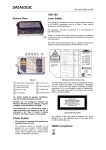
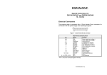
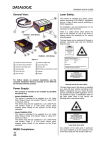
1
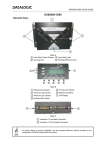
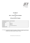
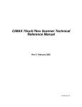
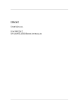
76xx/7200/7400
Utility Interface Box
User’s Manual
EM-63217-2E
Rev E
SICK Auto Ident, Inc.
5 Shawmut Road
Canton, MA 02021
(781) 302-2500
FAX (781) 828-3150
Copyright © SICK Auto Ident, Inc.
This manual and the software described in it are copyrighted, with all rights reserved. Under the copyright laws, no part of this
publication may be reproduced, stored in a retrieval system, or transmitted, in any form by any means, electronic, mechanical,
by photocopying, recording, or otherwise, without prior written permission of SICK Auto Ident, Inc.
Information furnished by SICK Auto Ident, Inc. is believed to be accurate and reliable and is subject to change without notice.
However, no responsibility is assumed by SICK Auto Ident, Inc. for its use or any errors that may appear in this document, nor
for any infringements of patents or other rights of third parties, which may result from its use.
Factory Authorized Training
SICK Auto Ident, Inc. provides comprehensive product training. Contact the SICK Auto Ident, Inc. Training Coordinator at 1888-264-4641 for in-house and on-site class schedules and rates.
Getting Assistance
If you have questions or comments, please contact SICK Auto Ident, Inc. at 1-888-264-4641. For additional assistance, contact:
•
Order Processing (Option #1)
•
Technical Support (Option #2)
•
Field Service Contracts (Option #3)
•
Customer Service Fax (781) 828-3150
Product names mentioned herein are for identification purposes only and may be trademarks and/or registered trademarks of
their respective companies: OMNI, CiComm, CiFrame, CiMenu, CiMAX, CiPRO, CiBOS, Scanstar, Starnode, and TALL
Other references to trademarks are the rights of their respective owners.
Printed in the United States of America
Contents
Contents
CHAPTER 1
Setup and Use
1
Introduction 1
Features 2
Description 4
AC Input Power (A1-63207-2 only) 4
DC Input Power (A1-63207-3 only) 5
Making Connections 6
Scanner to Utility Interface Box 6
Main and Auxiliary Communications Ports 8
Presence Sensor Input and Scanner Outputs 10
Setting LED Output Jumpers 12
Setting Presence Sensor Jumpers 12
Rev E, February 2002
76xx/7200/7400 Utility Interface Box
iii
Contents
Scanner Setup 14
Setting Scanner Parameters 14
Setting Up for Master/Slave Configurations 17
Setting Up for Pass Through Configurations 19
Technical Specifications
21
Electrical 21
Inputs 21
Outputs 21
Communications 22
Cables 22
Mechanical Assembly 23
Printed Circuit Board 24
Index
iv
25
76xx/7200/7400 Utility Interface Box
Rev E, February 2002
Introduction
CHAPTER 1
Setup and Use
Introduction
This manual describes the functionality and use of the following products:
•
A1-63207-2: 76xx/7200/7400 AC/DC Utility Interface Box
•
A1-63207-3: 76xx/7200/7400 DC/DC Utility Interface Box
WARNING! THIS PRODUCT IS INTENDED ONLY FOR INSTALLATION IN AN ELECTRICAL
JUNCTION BOX, AND SHOULD BE INSTALLED ONLY BY A QUALIFIED ELECTRICIAN.
Rev E, February 2002
76xx/7200/7400 Utility Interface Box
1
Introduction
Features
The main features of the Utility Boxes are:
•
1 Presence input connection for CiPro-7200/7400, NPN or PNP presence sensor
•
3 input connections for CiMAX-76xx
•
3 output connections
•
Main plug-in connector for RS232 or RS485 communication (DB9F)
•
Auxiliary plug-in connector for RS232 communication (DB9M)
•
Three LEDs controlled by the scanner’s output signals (Jumper selectable)
The top plate with the connectors and components must be mounted onto the junction box, as shown in
Figure 1.
2
76xx/7200/7400 Utility Interface Box
Rev E, February 2002
Introduction
FIGURE 1.
76xx/7200/7400 AC/DC Utility Interface Box
Note: Lead all wiring through the large knockout holes in the junction box, using proper bushing hardware.
Rev E, February 2002
76xx/7200/7400 Utility Interface Box
3
Introduction
Description
The 76xx/7200/7400 AC/DC Utility Interface Box (A1-63207-2) (‘AC Utility Box’) and the 76xx/7200/
7400 DC/DC Utility Interface Box (A1-63207-3) (‘DC Utility Box’) consist of a printed circuit board,
mounted on a cover plate, which is intended to fit within a quad utility box. These utility boxes provide
power to a CiMAX-76xx, CiPro-7200, or a CiPro-7400 scanner, and allow easy connection to scanner
inputs, outputs, and communications signals.
AC Input Power (A1-63207-2 only)
The terminal block TB1 on the printed circuit board is used to connect a 100-240VAC source.
TABLE 1. AC
Input Power
Pin
Name
Function
1
LINE
100-240VAC Line (Brown)
2
NEUT
100-240VAC Neutral (Blue)
3
CHG
100-240VAC Ground (Green/Yellow)
4
76xx/7200/7400 Utility Interface Box
Rev E, February 2002
Introduction
DC Input Power (A1-63207-3 only)
The terminal block TB3 on the printed circuit board is used to connect an 18-36 VDC source.
Note: Do not connect Input Ground to Earth Ground. Earth Ground is used for shielding purposes.
TABLE 2. DC
Input Power
Pin
Name
Function
1
DCIN+
DC Input + Voltage
2
DCIN-
DC Input Ground
3
CHG
Earth Ground
Rev E, February 2002
76xx/7200/7400 Utility Interface Box
5
Making Connections
Making Connections
Scanner to Utility Interface Box
The DB25 plug on the Utility Box cover plate mates with the DB25 socket that terminates the CiPro-7200
and CiPro-7400 scanner cable.
When connecting the CiMAX-76xx scanner, you must use either (A1-63345-1) or (A1-63345-2) 8 foot
cables. All power, communications, input, and output signals are present on the DB25. The A1-63345–2
cable makes no communication connections to the CiMAX-76xx scanner, so communications must be made
to the scanner itself. The (A1-63345-1 rev B) and (A1-63345-2 rev C) have the additional input 3
connection, if required. Previous revisions of these cables do not.
TABLE 3. Utility
Box DB25 Pin Assignments
CiPro-7200/7400 Scanners
CiMAX-76xx Scanner
Pin
Name
Function
Name
Function
1
CHASSIS
Chassis ground
CHASSIS
Chassis ground
2
TX232/TX485+
Main port
Host TXD
Host port
3
RX232/RX485+
Main port
Host RXD
Host port
6
76xx/7200/7400 Utility Interface Box
Rev E, February 2002
Making Connections
TABLE 3. Utility
Box DB25 Pin Assignments (Continued)
4
RTS232/TX485-
Main port
NC
No connect
5
CTS232/RX485-
Main port
NC
No connect
6
NC
No connect
IN3
Input 3
7
SGND
Signal ground
SGND
Signal ground
8
NO READ +
‘No Read’ output
OUT1
Output 1
9
VS
Presence supply
+12V
Power supply voltage
10
NC
No connect
NC
No connect
11
RIGHT+
‘Right’ output
OUT2
Output 2
12
RIGHT-
‘Right’ output
SGND
Signal ground
13
VS
Power supply
+12V
Power supply voltage
14
WRONG+
‘Wrong’ output
OUT3
Output 3
15
WRONG-
‘Wrong’ output
SGND
Signal ground
16
NC
No connect
NC
No connect
17
NC
No connect
NC
No connect
18
PS+
Presence sensor
IN1
Input 1
Rev E, February 2002
76xx/7200/7400 Utility Interface Box
7
Making Connections
TABLE 3. Utility
Box DB25 Pin Assignments (Continued)
19
PS-
Presence sensor
IN2
Input 2
20
RXAUX
Auxiliary port
TERMRXD
Terminal port
21
TXAUX
Auxiliary port
TERMTXD
Terminal port
22
NO READ-
‘No Read’ output
NC
No connect
23
CTSAUX
Auxiliary port
NC
No connect
24
RTSAUX
Auxiliary port
NC
No connect
25
SGND
Signal ground
NC
No connect
Main and Auxiliary Communications Ports
The Main DB9 socket on the cover plate is for access to the Main/Host communications port. Use a straight
through 9-pin male/female cable to connect the Utility Box DB9 to a PC serial port to program the scanner
and receive data.
8
76xx/7200/7400 Utility Interface Box
Rev E, February 2002
Making Connections
TABLE 4. Main
DB9F Pin Out
Pin
Name
Function
1
MAINRTS/TX485-
Main port (output)
2
MAINTX232/TX485+
Main port (output)
3
MAINRX232/RX485+
Main port (input)
4
MAINCTS/RX485-
Main port (input)
5
SGND
Signal ground
6,7,8,9
NC
No connect
The AUX DB9 plug on the cover plate is for access to the AUX communications port. Use a straight through
9-pin male/female cable to connect the Utility Box DB9M to an additional standard utility box, if that
scanner is set up in pass through mode. The Auxiliary port is also used in CiPro-7200/7400 verifier mode.
Rev E, February 2002
76xx/7200/7400 Utility Interface Box
9
Making Connections
TABLE 5. Auxiliary
DB9M Pin Assignments
Pin
Name
Function
1
AUXCTS
Auxiliary port handshake (input)/Verifier Mode
2
AUXRX232
Auxiliary port RS232 (input)
3
AUXTX232
Auxiliary port RS232 (output)
4
AUXRTS
Auxiliary port handshake (output)/Verifier Mode
5
SGND
Signal ground
6,7,8,9
NC
No connect
Presence Sensor Input and Scanner Outputs
The terminal block TB2 on the printed circuit board is used to access scanner inputs and outputs, and
provides +12V for Presence sensor and/or relays.
Note: Although the input and outputs are opto-isolated at the CiPro-7200/7400 scanner, they are single
ended (referenced to Signal ground) on the Utility Box terminal strip.
10
76xx/7200/7400 Utility Interface Box
Rev E, February 2002
Making Connections
TABLE 6. TB2
Pin Out
Pin
Name
CiPro-7200/7400 function
CiMAX-76xx function
1
2
GND
Signal ground
Signal ground
+12V
Power for presence sensor, relays
Power for presence sensor, relays
3
O1
Scanner output: No Read
Output 1: No Read Led
4
O2
Scanner output: Right
Output 2: Match Led
5
O3
Scanner output: Wrong
Output 3: No Match Led
6
GND
Signal ground
Signal ground
7
I1/P+
+ Input from presence sensor (PNP)
Input 1
8
I2/P-
- Input from presence sensor (NPN)
Input 2
9
I3
Not used
Input 3
10
GND
Signal ground
Signal ground
Rev E, February 2002
76xx/7200/7400 Utility Interface Box
11
Making Connections
Setting LED Output Jumpers
The jumpers JH1, JH2, JH3 are used to connect outputs 1, 2, 3 to the LEDs respectively. These are set to
OFF in the default position. The LEDs are pulled up to +12V and should be used only if no output
connections are made to TB2.
Setting Presence Sensor Jumpers
The jumper header J2 is used to configure the interface box for various types of input configurations. The
factory default jumper positions are for a CiMAX-76xx scanner.
•
For a CiPro-7200/7400 NPN presence sensor, place one shunt over pins 1 and 2, and the other shunt
over pins 3 and 4. Presence will be active when a low signal is placed on the P- input.
•
For a CiPro-7200/7400 PNP presence sensor, place one shunt over pins 2 and 3, and the other shunt
over pins 4 and 5. Presence will be active when a high signal is placed on the P+ input.
•
For a CiMAX-76xx scanner, place one shunt over pins 2 and 3, and the other shunt over pins 6 and 7.
Inputs will be active when a low signal is placed on any of the three inputs.
12
76xx/7200/7400 Utility Interface Box
Rev E, February 2002
Making Connections
FIGURE 2.
Presence Sensor Jumper Settings
Position for CiPro-7200/7400
Position for CiPro-76xx
PNP sensor
NPN sensor
J2
J2
+12 V
76xx/7200/7400 Utility Interface Box
GND
+12 V
TB2
Rev E, February 2002
GND
TB2
+12 V
TB2
GND
J2
13
Scanner Setup
Scanner Setup
Setting Scanner Parameters
To set the CiPro-7200/7400 scanner parameters, connect a straight through type 9-pin male/female cable
between the Utility Box Main DB9F and a PC serial port. Then, use the CiWINSET Windows-based
program to set scanner parameters as desired.
Scanning in the CiPro-7200/7400 Verifier Code
The CiPro-7200/7400 scanner can scan in a code, which will be used as the Verifier code. The Utility Box
provides an easy method to use this feature.
The procedure requires setting parameters from CiWINSET, and installing a hardware jumper.
Note: Scanning in the Verifier label saves the full scanner configuration (all parameter settings, including
the scanned-in Verifier code) to the scanner’s memory (EEPROM). Make sure ALL parameters have the
correct values before performing this procedure.
1.
Set the Multi label parameter to ‘Disabled.’
2.
Set the group of parameters under ‘Code 1’ (Type, Digit Number, etc.), for the Verifier label to be
scanned.
14
76xx/7200/7400 Utility Interface Box
Rev E, February 2002
Scanner Setup
3.
Set the Auxiliary Interface Mode parameter to ‘Disabled.’
4.
Set the Operating Mode parameter to any value except ‘Test’.
Note: It is recommended that you set this parameter to ‘Automatic’ (label is scanned automatically when the
scan line falls on it).
5.
Set the Code Verifier parameter to ‘Enabled.’
6.
Set the Store verifier HW parameter to ‘Enabled.’
7.
Jumper the RTSAUX pin to the CTSAUX pin; do this by removing any cable connected to the AUX
port and jumper pins 1 and 4 of the Utility Box DB9M plug on the Standard Utility Box.
8.
Scan the Verifier label. If the Operating Mode parameter is set to ‘Automatic’, simply present the label
to the scanner.
9.
Remove the jumper, and restore any cabling previously removed.
10.
From the CiWINSET Device Control panel, press the Get button.
The scanned-in Verifier label should appear in the Verifier Code Values parameter.
Rev E, February 2002
76xx/7200/7400 Utility Interface Box
15
Scanner Setup
11.
Set the Store verifier HW parameter to ‘Disabled.’
12.
Set the Auxiliary Interface Mode parameter to the desired value.
13.
Set the Operating Mode parameter to the desired value.
14.
From the CiWINSET Device Control panel, press the RAM/EEPROM button until EEPROM is
displayed, then press the Send button.
15.
Press the RAM/EEPROM button until the desired value is displayed.
16
76xx/7200/7400 Utility Interface Box
Rev E, February 2002
Scanner Setup
Setting Up for Master/Slave Configurations
Omni-directional reading systems with a single Master and up to 5 Slaves can be assembled using the Utility
Boxes. Each scanner is connected to a multi-drop RS485 network via its Main port. This requires creating a
3-wire cable with multiple male DB9 connectors (one for each scanner), connecting to pins 2 (TX485+), 1
(TX485-), and 5 (GND). The DB9s are then plugged into each scanner Utility Box. The Presence inputs are
jumpered together on all Utility Boxes and connected to the single Presence sensor. The Master scanner can
communicate with the PC host over the AUX port of the Standard Utility Box (DB9M).
Setting up a Master/Slave configuration requires setting scanner multi-drop addresses and setting software
parameters. Refer to the CiPro-7200/7400 User Manuals for specific information.
Rev E, February 2002
76xx/7200/7400 Utility Interface Box
17
Scanner Setup
FIGURE 3.
Master/Slave Configuration Setup
1 2 5 MAIN
DB9F
1 2 5 MAIN
DB9F
1 2 5 MAIN
DB9F
Utility Box
Utility Box
Utility Box
DB25F
TB2 DB9M
AUX
SLAVE 2
Scanner
DB25F
TB2 DB9M
SLAVE 1
Scanner
DB25F
TB2 DB9M
AUX
Presence
Sensor
18
MASTER
Scanner
AUX
Host
PC
76xx/7200/7400 Utility Interface Box
Rev E, February 2002
Scanner Setup
Setting Up for Pass Through Configurations
Pass through (daisy chain) mode also requires custom cabling. The first scanner in the chain is connected to
the PC host via its Main port, using a straight through 9-pin male/female cable from Utility Box #1 to the PC
serial port. Scanner #1 AUX port is connected to Scanner #2 Main port using a straight through cable.
Scanner #2 AUX port is connected to Scanner #3 Main port using a straight through cable, and so on down
the line. Each scanner has its own Presence sensor.
Wire each scanner-to-scanner cable as follows:
Scanner (n) AUX port
(Utility Box terminal strip)
Scanner (n+1) Main port
(Utility Box DB9)
TXAUX (DB9M Pin 3)
to
RX232 (DB9F pin 3)
RXAUX (DB9M Pin 2)
to
TX232 (DB9F pin 2)
GND (DB9M Pin 5)
to
GND (DB9F pin 5)
RTSAUX (DB9M Pin 4) to
CTS (DB9F pin 4)
CTSAUX (DB9M Pin 1) to
RTS (DB9F pin 1)
Rev E, February 2002
76xx/7200/7400 Utility Interface Box
19
Scanner Setup
Setting up a Pass-through configuration requires setting software parameters. Refer to the CiPro-7200/7400
User Manuals for specific information.
FIGURE 4.
Pass Through Configuration Setup
Host PC
DB9F
Utility Box #3
DB25
TB2 DB9M
DB9F
DB9F
scanner
#3
Utility Box #2
DB25
scanner
#2
TB2 DB9M
aux port
Presence
Sensor
20
Presence
Sensor
76xx/7200/7400 Utility Interface Box
Utility Box #1
DB25
scanner
#1
TB2 DB9M
aux port
Presence
Sensor
Rev E, February 2002
Technical Specifications
Technical Specifications
Electrical
Input power (A1-63207-2):
Input power (A1-63207-3):
Output voltage to scanner:
Output power, max:
Operating temperature:
100-240VAC, 50-60Hz
18-36VDC
+12VDC
15W
0-55°C
Inputs
One Presence Sensor input (CiPro-7200/7400). Configurable as NPN or PNP
Three inputs (CiMAX-76xx)
+12VDC provided for sensor power
Outputs
Three outputs: No Read, Match, and No Match
+12VDC provided for relay power
Rev E, February 2002
76xx/7200/7400 Utility Interface Box
21
Technical Specifications
Communications
Full access to Main port (RS232)
Access to Auxiliary port (RS232)
Ability to scan Verifier code (CiPro-7200/7400)
Cables
A1-63345-1
A1-63345-2
966-0128-1
22
CiMAX-76xx full connectivity 8 foot cable
CiMAX-76xx non communication 8 foot cable
2 meters 9-pin male/female cable
76xx/7200/7400 Utility Interface Box
Rev E, February 2002
Mechanical Assembly
Mechanical Assembly
FIGURE 5.
Utility Box A1-63207-2, 3
Rev E, February 2002
76xx/7200/7400 Utility Interface Box
23
Mechanical Assembly
Printed Circuit Board
FIGURE 6.
24
Printed Circuit Board
76xx/7200/7400 Utility Interface Box
Rev E, February 2002
Index
Index
F
Features 2
M
Main Ports 8
Mechanical Assembly 23
P
Presence Sensor Input 10
A
AC Input Power 4
Auxiliary Ports 8
C
Connections
scanner to interface box 6
D
DB9
pin out of auxiliary 10
pin out of main 9
DC Input Power 5
Rev E, February 2002
S
Scanner Outputs 10
Scanning in
CiPro-7200/7400 verifier code 14
Setting
LED output jumpers 12
presence sensor jumpers 12
scanner parameters 14
Setting Up
master/slave configurations 17
pass through configurations 19
Specifications 21
76xx/7200/7400 Utility Interface Box
25