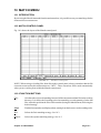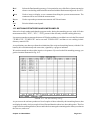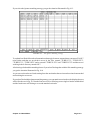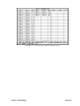
1
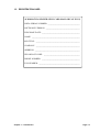
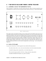
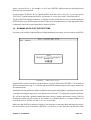
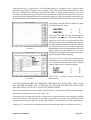
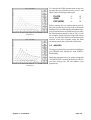
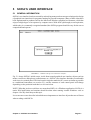
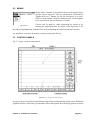
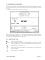
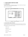
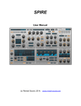
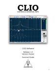
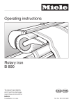
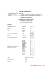
© Copyright 1995-96 by AUDIOMATICA SRL All Rights Reserved Edition 1.01, April 1996 IBM is a registered trademark of International Business Machines Corporation. Windows is a registered trademark of Microsoft Corporation. CONTENTS 1 INTRODUCTION .............................................................................. 1-1 1.1 GENERAL CONDITIONS AND WARRANTY ...................................................... 1-1 1.2 REGISTRATION CARD ....................................................................................... 1-2 2 THE SOFIA VACUUM TUBES CURVE TRACER ........................... 2-1 2.1 2.2 2.2 2.3 2.4 A GENERAL LOOK AT THE HARDWARE OF SOFIA ........................................ 2-1 SOFIA 'S TOP PANEL ......................................................................................... 2-1 ACCESSORIES SUPPLIED ................................................................................ 2-2 SOFIA'S SYSTEM SOFTWARE .......................................................................... 2-2 TECHNICAL SPECIFICATIONS.......................................................................... 2-2 3 INSTALLING AND USING SOFIA ................................................... 3-1 3.1 3.2 3.3 3.4 3.5 PC CONFIGURATION ......................................................................................... 3-1 HARDWARE INSTALLATION ............................................................................. 3-1 SOFTWARE INSTALLATION .............................................................................. 3-1 RUNNING SOFIA FOR THE FIRST TIME ........................................................... 3-2 ADVICES ............................................................................................................. 3-4 4 PC COMPATIBILITY ........................................................................ 4-1 4.1 HARDWARE COMPATIBILITY............................................................................ 4-1 4.2 SOFTWARE COMPATIBILITY ............................................................................ 4-1 5 SOFIAS USER INTERFACE ........................................................... 5-1 5.1 5.2 5.3 5.4 GENERAL INFORMATION.................................................................................. 5-1 MENUS ................................................................................................................ 5-2 CONTROL PANELS ............................................................................................ 5-2 HOT KEYS........................................................................................................... 5-4 6 DISK MENU ...................................................................................... 6-1 6.1 6.2 6.3 6.4 6.5 6.6 6.7 6.8 INTRODUCTION ................................................................................................. 6-1 DATA FILE ORGANISATION .............................................................................. 6-1 Load ..................................................................................................................... 6-1 Save..................................................................................................................... 6-2 Mkdir .................................................................................................................... 6-2 Chdir .................................................................................................................... 6-3 Setup ................................................................................................................... 6-3 Exit ....................................................................................................................... 6-3 7 SOFIA'S SOFTWARE SETUP ......................................................... 7-1 7.1 INTRODUCTION ................................................................................................. 7-1 7.3 THE DISK Setup CHOICE ................................................................................... 7-1 7.3.1 PRINTERS ............................................................................................... 7-1 7.3.2 COLORS .................................................................................................. 7-1 7.3.3 SERIAL PORT ......................................................................................... 7-1 7.4 THE SETUP FILE ................................................................................................ 7-1 8 MEASURE MENU ............................................................................ 8-1 8.1 INTRODUCTION ................................................................................................. 8-1 8.2 MEASURE PLATE CONTROL PANEL ............................................................... 8-1 8.2.1 FUNCTION BUTTONS ............................................................................ 8-1 8.2.2 THE STATUS AREA ................................................................................ 8-2 8.2.3 THE TUBE DATA DIALOG BOX ............................................................. 8-3 8.2.4 THE MEASUREMENT SETTINGS DIALOG BOX ................................... 8-5 8.3 HOW TO MEASURE A TUBE ............................................................................. 8-6 8.3.1 INPUT OF ELECTRICAL AND MECHANICAL DATA ............................. 8-6 8.3.2 CONNECTION OF TUBE TO SOFIA'S TERMINALS .............................. 8-6 8.3.3 MEASUREMENT CARRYING OUT AND MANAGEMENT ..................... 8-7 8.4 MEASURING MODES ......................................................................................... 8-9 8.4.1 NORMAL.................................................................................................. 8-9 8.4.2 DUAL ....................................................................................................... 8-9 8.4.3 PSEUDO-TRIODE ................................................................................. 8-10 8.4.2 ULTRA-LINEAR ..................................................................................... 8-10 8.5 CONNECTIONS ................................................................................................ 8-11 8.5.1 DIODES ................................................................................................. 8-11 8.5.2 TRIODES ............................................................................................... 8-12 8.5.3 TETRODES AND PENTODES .............................................................. 8-12 8.6 THE MEASURE QC CONTROL PANEL ........................................................... 8-13 8.6.2 FUNCTION BUTTONS .......................................................................... 8-13 8.6.2 OPERATING WITH THE QC CONTROL PANEL .................................. 8-14 8.6.3 THE QC SETUP FILE ............................................................................ 8-14 8.6.4 THE QC SESSION REPORT FILE ........................................................ 8-15 9 SOFIA'S MAIN CONTROL PANEL .................................................. 9-1 9.1 INTRODUCTION ................................................................................................. 9-1 9.2 MAIN CONTROL PANEL OPERATION .............................................................. 9-1 10 MATCH MENU ............................................................................... 10-1 10.1 INTRODUCTION ............................................................................................... 10-1 10.2 MATCH CONTROL PANEL ............................................................................... 10-1 10.2.1 FUNCTION BUTTONS .......................................................................... 10-1 10.3 MATCHING STRATEGIES AND SOME EXAMPLES ....................................... 10-2 1 INTRODUCTION 1.1 GENERAL CONDITIONS AND WARRANTY THANKS Thank you for purchasing your SOFIA system. We hope that your experiences using SOFIA will be both productive and satisfying. CUSTOMER SUPPORT Audiomatica is committed to supporting the use of the SOFIA system, and to that end, offers direct support to end users. Our users all around the world can contact us directly regarding technical problems, bug reports, or suggestions for future software enhancements. You can call, fax or write to us at: AUDIOMATICA SRL VIA FAENTINA 244/G 50133 FLORENCE, ITALY PHONE: +39-055-575221 FAX: +39-055-5000402 AUDIOMATICA ON-LINE For having technical support, to get a list of international distributors, for any inquiry and to know the latest news about SOFIA and other Audiomatica's products we are on the Internet to help you: E-MAIL: [email protected] WWW: http://www.mclink.it/com/audiomatica AUDIOMATICAS WARRANTY Audiomatica warrants the SOFIA system against physical defects for a period of one year following the original retail purchase of this product. In the first instance, please contact your local dealer in case of service needs. You can also contact us directly as outlined above, or refer to other qualified personnel. WARNINGS AND LIMITATIONS OF LIABILITY Audiomatica will not assume liability for damage or injury due to user servicing or misuse of our product. Audiomatica will not extend warranty coverage for damage of the SOFIA system caused by misuse or physical damage. Audiomatica will not assume liability for the recovery of lost programs or data. The user must assume responsibility for the quality, performance and the fitness of Audiomatica software and hardware for use in professional production activities. and AUDIOMATICA are registered trademarks of Audiomatica SRL. Chapter 1 Introduction Page 1-1 1.2 REGISTRATION CARD AUDIOMATICA REGISTRATION CARD (MAIL OR FAX TO US) SOFIA SERIAL NUMBER: ________________________________ SOFTWARE VERSION: __________________________________ PURCHASE DATE: ______________________________________ NAME: ________________________________________________ JOB TITLE: ____________________________________________ COMPANY: ____________________________________________ ADDRESS: _____________________________________________ ZIP OR POST CODE: ____________________________________ PHONE NUMBER: ______________________________________ FAX NUMBER: _________________________________________ Chapter 1 Introduction Page 1-2 2 THE SOFIA VACUUM TUBES CURVE TRACER 2.1 A GENERAL LOOK AT THE HARDWARE OF SOFIA Sofia is housed in a stand alone box and is powered from the mains. On the top panel the most widespread tubes sockets are present, together with the routing system. Fig.2.1 shows Sofia's panel. POWER OFF ! WARNING ! POWER ON LETHAL VOLTAGES PRESENT WHEN LIT HAZARD VACUUM TUBES CURVE TRACER 1 2 3 4 5 6 7 8 9 BY AUDIOMATICA SERIAL HEATER+ HEATER- PLATE GRID SCREEN SUPPRESSOR CATHODE GROUND FIG.2.1 - Sofia's top panel Heart of the system are four high resolution (16 bit) voltage generators for filament, plate, grid, screen grid and three high resolution (16 bit) milliamperometers used to resolve the currents involved in this kind of measurements. The achieved resolution together with gain control facilities for voltage and current allows to measure tubes curves with enormous dynamic range. State of the art circuitry and sophisticated digital control greatly enhance reliability, a main topic in high voltage devices. A microprocessor handles both the RS-232 link to the PC and the internal logic requirements. The flexible manual routing system makes easy the connection of tubes that dont fit in the sockets provided; furthermore allows several circuital configurations (cascode, srpp ...) to be evaluated as a single tube. 2.2 SOFIA 'S TOP PANEL As you can see from Fig.2.1 Sofia's top panel comes with the following features: - Four tube sockets (four, seven, octal, noval) internally wired to the numbered terminals. - A manual routing system composed by several connecting cords. - The coloured output terminals of the four voltage genarators and grounds. - The RED HAZARD LED and the two yellow serial leds. Chapter 2 The SOFIA Vacuum Tubes Curve Tracer Page 2-1 - The power switch. CAUTION: SOFIA IS ABLE TO GENERATE VERY HIGH VOLTAGES THAT MAY CAUSE YOU SEVERE INJURIES; PAY ATTENTION TO THE RED HAZARD LED; WHEN THE HAZARD LED IS LIT DO NOT TOUCH THE INSTRUMENT. The two yellow serial leds signal the occurring serial data transfer. 2.2 ACCESSORIES SUPPLIED Sofia comes with the following: - User's Manual and System Software - 7 coloured connecting cords - 1 splitting cord - 1 AC mains cable - 1 RS-232 9-to-9 pins connecting cable 2.3 SOFIA'S SYSTEM SOFTWARE A powerful Windows-like software with a mouse oriented user interface allows an immediate control over all the measure processes. Refer to the following chapters for a detailed description of its functionality. Basic tubes parameters as transconductance, plate resistance and amplification factor are shown in real time for any operating area within the displayed curves. Sofias system software handles tube directories containing all the manufacturers mechanical data and electrical measurement limits. Automatic pass-fail QC control routines makes easy and quick any tube selection process. Automatic best match between couple or more tubes within a batch is also included. 2.4 TECHNICAL SPECIFICATIONS DC GENERATORS Type: 4 channels voltage generator Resolution: 16 bit Plate voltage range: 0÷700 V Grid screen voltage range: 0÷700 V Filament voltage range: 0÷24V Filament max. supply current: 5A Grid voltage range: +10÷-150 V Chapter 2 The SOFIA Vacuum Tubes Curve Tracer Page 2-2 DC ANALYZERS Type: 3 channels milliamperometer Resolution: 16 bit ROUTING SYSTEM Type: manual with supplied cords Test sockets furnished: - Octal - Noval - Four - Transmitting seven PC CHARACTERISTICS REQUIRED 80286 or more 640 Kbytes RAM or more VGA video adapter or more Hard Disk Free RS-232 port Co-processor required MISCELLANEOUS Dimensions (approx.): 44x24x12 cm. Weight: 7 Kg. AC voltage: 110-120 220-240 V AC power consumption: 200W Chapter 2 The SOFIA Vacuum Tubes Curve Tracer Page 2-3 3 INSTALLING AND USING SOFIA NOTE: PLEASE REFER TO CHAPTER 4 FOR POTENTIAL PROBLEMS REGARDING THE COMPATIBILITY OF SOFIA WITH YOUR PC (EITHER HARDWARE OR SOFTWARE). 3.1 PC CONFIGURATION SOFIA can be connected to any IBM (or compatible) personal computer with the following mimimum system requirements: 286 processor one free RS-232 serial port available 640 kB RAM hard disk VGA video board MS-DOS Version 3.2 or later A math coprocessor is highly recommended although not necessary. 3.2 HARDWARE INSTALLATION This installation is as simple as connecting the SOFIA cabinet to the AC mains and to a free serial connector of your PC with an appropriate serial cable. WARNING: before connecting SOFIA to a wall AC outlet make sure that your unit is properly set for AC voltage; in case of any doubt refer to your local assistance. WARNING: depending on the connector of RS-232 port use either the supplied 9-to-9 pins serial cable or a 25-to-9 pins serial cable or a 25-to-9 pins BIDIRECTIONAL RS-232 adaptor: DO NOT use 9-to-25 pins mouse adaptors, the connection would not work. CAUTION: SOFIA IS ABLE TO GENERATE VERY HIGH VOLTAGES THAT MAY CAUSE YOU SEVERE INJURIES; PAY ATTENTION TO THE RED HAZARD LED; WHEN THE HAZARD LED IS LIT DO NOT TOUCH THE INSTRUMENT. 3.3 SOFTWARE INSTALLATION The SOFIA software is provided on a 3.5" (1.44 MB) diskette named PROGRAM DISK. The software has to be installed on the hard disk of your PC. The installation procedure is carried out by running the INSTALL.BAT batch file that is supplied on the program disk. This will create a SOFIAxx directory and one subdirectory called DATA. xx denotes the software version number. For this edition the actual version number is 1.0, so a SOFIA10 directory will be created. To install the SOFIA software do the following: 1) Insert the PROGRAM DISK in your PC. 2) Type the following command: INSTALL {optional source drive}{optional destination drive}<ENTER> Chapter 3 Installation Page 3-1 where {optional drive} is, for example, A: or D: and <ENTER> indicates that you should press the Enter key on your keyboard. As an example "INSTALL B: D:" installs SOFIA from drive B: to drive D:; if you only specify "INSTALL" without arguments SOFIA will assume A: source drive and C: destination drive. The DOS PATH should not contain the C:\SOFIA10 path; SOFIA has not to be run from outside the SOFIA10 directory! SOFIA requires at least 575K of conventional memory; use the appropriate DOS command to check this requirement before running SOFIA. 3.4 RUNNING SOFIA FOR THE FIRST TIME If you have successfully completed the preceding installation procedures, you are ready to run SOFIA! FIGURE 3.1 SOFIA's main window Switch SOFIA on and, in order to run the software, just type SOFIA and <ENTER>. You should see SOFIA's main window (Fig. 3.1). After having answered the initial prompt you are ready to make your first measurement. Should there be any problem with the installation the program will display a warning message. In the event that a warning message does occur, please refer to section 7.3.3 to properly setup the serial link. We will now deal with a guided example that shows how to connect and measure a tube. The first assumption is that you have a tube in your hands; we will think that it is a common 6DJ8 (or an equivalent 6922 or ECC88 or E88CC etc. etc.) twin triode. Make sure that SOFIA's connection system is free from any connecting chord and insert the tube in the noval socket; press M and then <ENTER>: you will see, for the first time, the Measure Plate Chapter 3 Installation Page 3-2 control panel (Fig.3.2); now press F1: the Tube data dialog box will appear (Fig.3.3) and you have learnt the usage of the F1 Hot Key, refer to chapter 5.4 for a list of all the other active Hot Keys; from the list of available tubes data files select the 6DJ8.TBE one either double-clicking on it or first selecting it and then pressing L to load it; the pin description available for this tube will lead you in the proper manual configuration of the connection system; let's start from turning on the tube: take the two chords with white plugs and, as described in the PIN 4 and PIN 5 fields (FIL stays for filament but one may write HEATER or whatever), make the following connections: HEATER+ HEATER- FIGURE 3.2 ð ð Now press O for Ok: the Tube data dialog box disappears and the Start, Fil and Dual function buttons are now active; note also that the Tube Name box shows the correct 6DJ8 name; press F: the filament function button is now active and the tube should be heated, you should see the serial leds flashing for a few seconds and then a reassuring ligth coming from the filament of your tube; shuold this not happen check all the procedure again starting from the beginning . We have now to connect the remaining tube terminals; press F1 again, the pin description tells us to make the following connections (with the chords with red, green and black plugs): PLATE GRID CATHODE FIGURE 3.3 ð ð ð Press <ESC>: we're now ready to start the first measurement. CAUTION: SOFIA IS ABLE TO GENERATE VERY HIGH VOLTAGES THAT MAY CAUSE YOU SEVERE INJURIES; PAY ATTENTION TO THE RED HAZARD LED; WHEN THE HAZARD LED IS LIT DO NOT TOUCH THE INSTRUMENT. Press S; the measurement is now running and after about 30 seconds you will be prompted with the output plate characteristics of your tube (Fig. 3.4)! You can now freely inspect this family of output curves by means of the cursor dragging it with the mouse; the software will calculate, in real-time, and display in the status area at the right of the measurement screen the values of Gm, Mu, Rp, Voltage, Current and Power of the selected point. Now press F2: you can save the measurement to a file on the hard disk; to recall it later use F3. Chapter 3 Installation Page 3-3 To complete the 6DJ8 measurement we have to measure the second triode section; press F1 and check for the following connections: PLATE GRID CATHODE FIGURE 3.4 ð ð ð Before starting the new measurement press O; this will activate the Overlay mode so that both families of curves will be displayed simultaneously; press S to measure the second triode of your tube; the final situation should be like in Fig.3.5 with the complete characterization of the tube on the screen; you will learn later how to measure both sections of the tube together using the Dual measuring mode and a particular connection. 3.5 ADVICES We suggest you to take some time for reading the User Manual and familiarize with SOFIA's functionality. Particular attention has to be paid to paragraph "5.4 HOT KEYS"; learning the hot keys will save you time during your job and enhance your productivity. FIGURE 3.5 Chapter 3 Installation Page 3-4 4 PC COMPATIBILITY 4.1 HARDWARE COMPATIBILITY Provided the availability of a standard RS-232 serial port Sofia has not showed, at the moment, any problem regarding compatibility with IBM-PC or compatibles personal computers. 4.2 SOFTWARE COMPATIBILITY A brief note is due regarding the Windows95 environment: The Sofia software program is NOT a Windows application; the performances and characteristics described in this manual are guaranteed under the assumption that the program is run under a DOS session. Chapter 4 PC Compatibility Page 4-1 5 SOFIAS USER INTERFACE 5.1 GENERAL INFORMATION SOFIAs user interface has been created by embodying many modern concepts relating to the design of graphical user interfaces for programs running on personal computers. Many of these ideas have been implemented in products such as the Microsoft Windows graphical environment, which has enjoyed a high degree of acceptance by computer users. With such a philosophy as an inspiration, which today is a commonly recognized standard, the SOFIA program should be easy for the user to comprehend and operate. FIGURE 5.1 SOFIA's startup screen and user interface Fig. 5.1 shows SOFIAs initial screen. Aside from normal graphical user interface objects such as menus, scroll bars, dialog boxes, radio buttons, etc., SOFIAs user interface furnishes a comfortable work area via a control panel. This has been developed to make the PC screen as similar as possible to a traditional instrument (see section 5.3), and the contents of each control panel will change depending on the particular task that is to be carried out. NOTE: What has just been said does not mean that SOFIA is a Windows application; SOFIA is a native DOS application and cautions should be taken when running it under Windows: refer to chapter 4 for any detail aboyut this topic. Let us now move on to describe in detail the most important user interface objects that one will meet when working with SOFIA. Chapter 5 SOFIAs User Interface Page 5-1 5.2 MENUS Menus allow a number of operational choices to be gathered into specific subject categories. They are structured in a hierarchical upside-down tree manner (as are the directories of a disk). SOFIAs main window, which is a menu in itself, is at the highest level (equivalent to the root directory of a disk). FIGURE 5.2 Choices may be made by either positioning the mouse or by entering the underlined letter by means of the keyboard, or by moving the highlighted bar with the arrow keys and making the selection with the Enter key. It is possible to exit from all menus by simply pressing the Esc key. 5.3 CONTROL PANELS Fig. 5.3 shows a typical control panel. FIGURE 5.3 A typical control panel In general, the screen will be divided into three physically and functionally distinct areas. Within the graphical window, whose title gives the name of the control panel, the following regions are present: Chapter 5 SOFIAs User Interface Page 5-2 THE MEASUREMENT SCREEN This represents the screen of a traditional instrument, and it occupies the major part of the window and presents the results obtained from the measurement that was executed. NOTE: It is normally possible to check results of a measurement through the use of an on-screen cursor. This can be directly activated with the mouse (dragging is possible by keeping the left button pressed). The numerical values associated with a given point on the graphical plot will usually be written on the status line (see above). FUNCTION BUTTONS These are found immediately under the measurement screen, and they represent the buttons that might normally be present on the instruments panel. Each button has a label that serves to describe its function. By selecting these buttons, it is possible to execute the measurement and check parameters. These function buttons may be pressed by positioning the mouse pointer on top of the selected function button and then clicking the left mouse button. It is also possible to make a selection by pressing the key on your keyboard that corresponds to the underlined letter on the button label. There are two different kinds of buttons. The most common one immediately returns to the starting position after being pressed, and this kind of button serves to confirm an action. The other type of button remains active when it is pressed, and changes colour to confirm that a particular operational mode has been selected. To deactivate such buttons it necessary to press them a second time. THE STATUS AREA This is located either between the function buttons and the end of the graphics window or at the side to the rigth of the measurement screen, and it is used to present useful messages to the user that help to enhance the understanding of the measurement. For example, these status messages include such things as the file name, the input overload status, the cursors position, as well as many others. Chapter 5 SOFIAs User Interface Page 5-3 5.4 HOT KEYS These are the keyboard keys that are always active from within any menu or control panel. They are a quick and convenient way to execute many of the most commonly used operations. They are not visible and therefore may not be selected with the mouse. After frequent use, these keys should become easy to remember. Let us now take a look at them in detail: F1 Recalls the tube data dialog box. F2 Saves the measurement on disk and activates the Save menu option. See section 6.4. F3 Loads a measurement and activates the Load menu option. See section 6.3. F4 Recalls the instrument control panel. F5 Used to change the working directory; activates the Chdir menu option. See section 6.6. F6 Creates a new directory on disk; activates the Mkdir menu option. See section 6.5. Alt-P Prints the executed measurements from within any control panel. To select the print options refer to the SOFIA SETUP chapter. Chapter 5 SOFIAs User Interface Page 5-4 6 DISK MENU 6.1 INTRODUCTION As you might expect from its title, this chapter deals with the functions that result in read or write access to and from the hard disk. Setup and Exit functions, although not logically tied to disk operations, are also present in this menu as they are of such common use. Before we begin examining each item on this menu, we strongly recommend that you read through the chapter describing the use of SOFIAs hot keys. Amongst other things, the hot keys allow the Load and Save commands to be quickly accessed from every other menu in the program. 6.2 DATA FILE ORGANISATION The SOFIA program is organised in a rather rigid structure on the hard disk, and this does not allow the user to wander around the directories. Data files containing measurements obtained by the user are gathered under the DATA subdirectory (which must in all cases be named as such), and under further subdirectories which the user may define whose prototype is the JOB1 directory (also obligatory). The JOB1 subdirectory is automatically created by the installation program. At the same level as that of the JOB1 directory, other directories may be created from within SOFIA by means of the Mkdir menu option found under the Disk command on the main menu bar. After a new directory has been created it may be made current through the Chdir menu option. All data files will be loaded or saved within the current directory. Last but not least, it is not possible to remove any kind of file and load or save on files on floppy disks from within the program. 6.3 Load By selecting this choice, the Load File dialog box, dedicated to those files belonging to the current subdirectory, will open (see also the F3 hot key). As shown in Fig. 6.1, this dialog box displays a list of files all of which have the same extension, and a series of buttons is used to select the extension (or rather the kind of measurement). These buttons are found on the bottom part of the window, and FIGURE 6.1 The Load File dialog box Chapter 6 Disk Menu Page 6-1 the Load and Cancel buttons are located towards the right hand side. The file name extensions that can be used are: Pte: measurement files obtained through the Measure Plate menu. Pt1: measurement files obtained through the Measure Plate menu in Dual mode. Pt2: measurement files obtained through the Measure Plate menu in Dual mode. To load the desired file, select it by using either the arrow keys on the keyboard or the mouse. Then either click the Load button, press the underlined letter L, or give a double-click with the mouse on the selected file name in the file list. It is possible to load, in sequence, files of all types, and these will be plotted once the related control panel has been accessed. 6.4 Save In Fig. 6.2 we can see the Save File window. The mode of operation is the same as that described for the Load File window. As might be expected, the filename extensions are also the same. You will automatically be prompted for the name of the file to be saved. FIGURE 6.2 The Save File dialog box Should there already be a file with the same name and extension, you will be asked to confirm the save operation. The directory in which the file is saved is the current active directory (see the Chdir and Mkdir menu commands for further details). Aside from the measurement itself, additional relevant information will also be saved. This includes a comment that can be added by means of the About button, as well as several settings related to the measurement. 6.5 Mkdir This command creates new work subdirectories that will be put under the DATA directory. All new directories are at the same level as the JOB1 directory which is created by the installation program. Therefore, it is possible to place sets of measurements into different subdirectories. When the SOFIA program is first loaded, the default directory where measurements and files of all extensions are saved is JOB1. Chapter 6 Disk Menu Page 6-2 6.6 Chdir This command is used to change the current directory where all measurements and files with different extensions will be saved to or loaded from. In order to be able to change to a particular directory, it must of course exist, and it will usually have been created using the Mkdir command. When exiting from SOFIA, the current directory will be saved in the SOFIA.STP file. When the SOFIA program is re-loaded, the last selected directory will be automatically selected. 6.7 Setup Refer to Chapter 7 SOFIA SETUP for a detailed explanation of this choice. 6.8 Exit This command ends the SOFIA work session. Chapter 6 Disk Menu Page 6-3 7 SOFIA'S SOFTWARE SETUP 7.1 INTRODUCTION This chapter explains how to correctly configure the SOFIA system software in order to obtain the best results when performing tubes parameters measurements. Section 7.2 will deal with some software configuration issues related to the SOFIA board that will affect all measurements. Section 7.3 will cover various aspects of configuration that are related to the PC platform (eg. printer devices) and are usually found in all software products. 7.3 THE DISK Setup CHOICE After choosing Setup from within the Disk command presented on the menu bar, one enters the Setup dialog box, which is shown in Fig.7.1. It is possible to configure your printer, on-screen colors, as well as SOFIAs serial connection from the various parameters displayed in this dialog box. FIGURE 7.1 - The Disk Setup dialog box 7.3.1 PRINTERS It is possible to select one of three popular printer families: Hewlett-Packard (HP), Epson, and IBM; otherwise the printout can be redirected to a standard Windows ".BMP" black-and-white bitmap file. It is also possible to set an option via a check box to send a form-feed command after each measurement is printed. 7.3.2 COLORS This option lets the user select from one of five different color choices. NOTE: Palettes 4 and 5 have been developed for use with monochrome displays. 7.3.3 SERIAL PORT It is possible to configure the serial port (COM1 or COM2) to which SOFIA is connected. 7.4 THE SETUP FILE All the above mentioned software configuration items are saved in a setup file called SOFIA.STP Chapter 7 SOFIA Setup Page 7-1 that is saved in the main SOFIA directory. This file will be loaded automatically every time SOFIA is started, thus re-configuring it to the last used state. NOTE: If, for any reason, you want to return to a known default condition, you can delete the SOFIA.STP file. This will cause the SOFIA software to load a built-in default configuration. Chapter 7 SOFIA Setup Page 7-2 8 MEASURE MENU 8.1 INTRODUCTION By selecting the Measure command from the main menu bar, it is possible to carry out tubes measurements and quality control. 8.2 MEASURE PLATE CONTROL PANEL Fig. 8.1 shows the layout of the Measure Plate control panel. FIGURE 8.1 The Measure Plate control panel NOTE: When saving or loading files from disk in this control panel, always remember that the file extension connected to this measurement are .PTE, .PT1 and .PT2. These extensions will be used automatically when you are working from within the Measure Plate control panel. 8.2.1 FUNCTION BUTTONS Start Starts a new tube measurement. See paragraph 8.2.4 for a description of how to measure a tube. Fil Turns the heater on. NOTE: to obtain the maximum precision of the filament voltage it is recommended to turn the filament on ONLY AFTER having inserted the tube in its socket: this is due to the current sensing mechanism involved during the warm-up time. If you insert a tube in its socket with the filament on the voltage may be slightly different if its filament current is different from the filament current of the previous tube heated. Chapter 8 Measure Menu Page 8-1 Dual Turns the Dual mode on. See paragraph 8.2.5. Tube Used to access the Tube Data dialog box. See paragraph 8.2.2. About Used to insert or display a text comment describing the present measurement. The comment will be saved with the measurement. Over Activates the overlap mode allowing for the overlaying of multiple curves. The visualised curves will be managed within a 2-location FIFO (first-in-first-out) buffer. Setting Enters the measurement settings dialog box. Exit Exits the Measure Plate control panel. →←↑↓ By pressing the arrow keys, or clicking on the corresponding buttons it is possible to change the displayed graphic scale for voltage and current. ← These keystroke combinations lets you ZOOM the displayed curves changing the left scale Ctrl→ →Ctrl← reference. 8.2.2 THE STATUS AREA Located to the right side of the Measure Plate control panel gives the following information: - Real-time calculation of Gm, µ and Rp related to marker position. - Real-time display of voltage, current and power related to marker position. - Name of measurement data file. - Name of Tube Data file. Chapter 8 Measure Menu Page 8-2 8.2.3 THE TUBE DATA DIALOG BOX From this dialog box is possible to manage, edit and display all the electrical and mechanical data of the tube under test. FIGURE 8.2 The Tube Data dialog box NOTE: When saving or loading files from disk in this control panel, always remember that the file extension connected to this measurement is .TBE. This extension will be used automatically when you are working from within this dialog box. WARNING: Audiomatica will not assume liability for the contents of the Tube Data files supplied in the distribution disk. These files are only meant as EXAMPLE files and descend from Audiomatica's experiences applied to tubes testing. ALWAYS refer to manufacturer's technical manual for exhaustive tube characteristics. Load Loads the selected tube data file from disk. Save Save the current tube data to disk. Ok Exits the tube settings dialog box accepting the displayed data. Cancel Exits the tube settings dialog box without accepting the displayed data. Pin 1-9 Description of the tube pins; useful to make the right connections on the SOFIA front panel. Mode Selects the kind of tube from within the following (see also 8.4): - Diode - Triode - Pentode (also included are tetrodes) - Pentode in pseudo-triode configuration - Pentode in ultra-linear configuration See paragraph 8.4 for a detailed description of how Sofia behaves when these choices are made. Npin Tube number of pins. Chapter 8 Measure Menu Page 8-3 Heat V Heater nominal voltage. [0÷24 V] Heat I Heater nominal current. [0÷5 A] Va max Plate maximum test voltage. [0÷700 V] Ia max Plate maximum test current. [0÷270 mA] Vsc Screen test voltage. When in Ultra-Linear mode reference screen quiescent voltage (see 8.4.2). [0÷700 V] Isc max Screen maximum test current. [0÷270 mA] P max Total test power dissipation (Plate + Screen). [0÷80 W] Vg max Grid maximum test voltage. [+10÷-150 V] Vg min Grid minimum test voltage. [+10÷-150 V] Ultra Percentage of the Ultra-Linear mode (see 8.4.2). [0÷100 %] Va0 Reference plate quiescent voltage in Ultra-Linear mode (see 8.4.2). [0÷500 V] Please note that, referring to the parameters ranges, the zero value is never allowed as input (except for Vgs, Igs and Va0); in these cases input a value grater than zero. Chapter 8 Measure Menu Page 8-4 8.2.4 THE MEASUREMENT SETTINGS DIALOG BOX Is used to input some settings useful during the measurement. FIGURE 8.3 The Measurement Settings dialog box Speed Selects the measurement speed. A different speed is obtained taking a different number of measurement points; the slower the speed the more accurate the curve measured. NumCurve Selects the number of curves that are measured, displayed and saved. Autosettle Tells Sofia to do the following things before starting a new measurement: - wait for a stable filament current - force the tube to a situation of maximum dissipation (in respect of what saved in the tube data) - wait for the parameters to be stable in this condition Autosave Tells Sofia to automatically save the measurement to disk in the current work directory. Files are saved with progressive names as "TUBExxxx.PTx" where xxxx is an ascending number; the first file will be "TUBE1.PTx" and so on. If there are already autosaved files in the directory the program will search for the first available free number and use it. Chapter 8 Measure Menu Page 8-5 8.3 HOW TO MEASURE A TUBE CAUTION: SOFIA IS ABLE TO GENERATE VERY HIGH VOLTAGES THAT MAY CAUSE YOU SEVERE INJURIES; PAY ATTENTION TO THE RED HAZARD LED; WHEN THE HAZARD LED IS LIT DO NOT TOUCH THE INSTRUMENT. This guided example explains the basic steps involved in measuring a vacuum tube: - Input of the electrical and mechanical data in the tubes archive. - Connection of the tube to Sofia's terminals. - Measurement carrying out and management. 8.3.1 INPUT OF ELECTRICAL AND MECHANICAL DATA Provided you have a vacuum tube in your hands, the first thing that you have to do is to tell Sofia its main electrical and mechanical data (see also 8.2.2); suppose you are dealing with an EL34 (or an equivalent 6CA7) beam pentode. If you take a look to the list of data files supplied with the distribution disk you may want to use the "EL34PENT.TBE" one (as in fig.8.2) or take a technical manual like Sylvania one and either control that the data in the existing file are correct or write a new one and save it to disk. Your experience will guide you to the best interpretation of the data in manuals so that all potentiality of Sofia will be applied to tube testing. NOTE: The impulsive technique exploited by Sofia when measuring families of curves lets usually extend the maximum dissipation beyond the value encountered in technical manuals; the power dissipation data in manuals are usually given in continuous drive conditions. WARNING: Audiomatica will not assume liability for the contents of the Tube Data files supplied in the distribution disk. These files are only meant as EXAMPLE files and descend from Audiomatica's experiences applied to tubes testing. ALWAYS refer to manufacturer's technical manual for exhaustive tube characteristics. 8.3.2 CONNECTION OF TUBE TO SOFIA'S TERMINALS The second step required is the electrical connection of the tube to Sofia; this is done first inserting the tube in the appropriate socket and then manually making the connections with the supplied connecting cords. Fig.8.4 shows the connection for the EL34 pentode. 1 HEATER+ 2 3 HEATER- PLATE 4 5 GRID SCREEN 6 7 SUPPRESSOR CATHODE 8 9 GROUND FIGURE 8.4 EL34 connections Chapter 8 Measure Menu Page 8-6 8.3.3 MEASUREMENT CARRYING OUT AND MANAGEMENT Should the first two steps be carried out one is now ready to perform the tube measurement. The measurement settings described in 8.2.3 and the status of the control panel function buttons together with the previously loaded Tube Data determine how the measurement will be done and managed. Before starting the actual measurement the tube has to be turned on; this is done by pressing the Fil function button thus delivering current to the tube heater. NOTE: it is good practice, before starting the measurement, to take a look at the tube and be sure that the filament is correctly powered; after the normal heater warm-up time (usually given in technical manual) you should see the reassuring red light coming from the heated element. WARNING: if you are not sure that the filament is on DO NOT PROCEED with measurement; this could lead permanent damage to the tube and eventually to Sofia. The following procedure is recommended should you be in troubles at this point: - Turn the filament off by pressing the Fil button. - Replace the cord from the HEATER+ terminal with the splitting cord. - Turn the filament on again and measure, with a voltmeter, the filament voltage between the HEATER+ and the GROUND terminals; refer to Fig.8.5 for connections. 1 HEATER+ 2 HEATER- 3 PLATE + 4 5 GRID SCREEN TO VOLTMETER 6 7 SUPPRESSOR CATHODE 8 9 GROUND - FIGURE 8.5 Connections to verify filament voltage NOTE: to obtain the maximum precision of the filament voltage it is recommended to turn the filament on ONLY AFTER having inserted the tube in its socket: this is due to the current sensing mechanism involved during the warm-up time. If you insert a tube in its socket with the filament on the voltage may be slightly different if its filament current is different from the filament current of the previous tube heated. If your tube is correctly heated you are ready to start the measurement pressing the Start function button. CAUTION: SOFIA IS ABLE TO GENERATE VERY HIGH VOLTAGES THAT MAY CAUSE YOU SEVERE INJURIES; PAY ATTENTION TO THE RED HAZARD LED; WHEN THE HAZARD LED IS LIT DO NOT TOUCH THE INSTRUMENT. A complete measurement usually takes several seconds; should you have any doubt and want to stop it press <ESC>: the measurement is immediately stopped. Chapter 8 Measure Menu Page 8-7 FIGURE 8.6 EL34 measurement If everything has gone ok you should be finally prompted with the awaited result as in Fig.8.6. The arrow keys and the cursor (that can be dragged keeping the left mouse button pressed) help you inspecting the measurement (refer to 8.2.2). If you want to save it press F2 and if you want to print it press Alt-P. Chapter 8 Measure Menu Page 8-8 8.4 MEASURING MODES Follows a brief description of hardware related arguments in order to better understand how Sofia is behaving in different situations; the next paragraph (8.5) gives a detailed description of the connections involved. 8.4.1 NORMAL This is the most common Sofia's operating mode. When in normal mode the four voltage generators operate independently; the software assumes that the proper tube terminal is connected to its corresponding voltage generator; let's see a typical connection of a triode (section one of a 6DJ8 twin triode): 1 HEATER+ 2 HEATER- 3 PLATE 4 5 GRID SCREEN 6 7 SUPPRESSOR CATHODE 8 9 GROUND FIGURE 8.5 Typical connections in normal mode 8.4.2 DUAL When the Dual operating mode is activated (see 8.2.1) Sofia thinks that a tube with two identical sections is connected and operates in a way that permits the simultaneous measurement of the two sections. Dual mode is particularly useful when you have to measure common twin triodes and full-wave rectifiers. To measure both sections simultaneously Sofia uses the Screen voltage generator for the plate of the second section and, in case of triodes, drives both grids together (you have to use the splitting cord when connecting); the cathode of the second section is connected to the Suppressor (or Ground) terminal; let's see how to connect a 6DJ8 twin triode to measure both sections together (note the use of the splitting cord between the Grid and terminal 7): 1 HEATER+ 2 HEATER- 3 4 5 6 PLATE GRID SCREEN SUPPRESSOR 7 CATHODE 8 9 GROUND FIGURE 8.5 Connection of a twin triode in dual mode NOTE: After the measurement is completed both families of curves are displayed together and the Overlay mode is activated. NOTE: When saving files in Dual mode the program creates two data files with extension .PT1 and .PT2. The files can be recalled later separately as a common ".PTE" file generated when saving in normal mode. Chapter 8 Measure Menu Page 8-9 8.4.3 PSEUDO-TRIODE The Pseudo-Triode is a special measuring mode for pentodes and tetrodes; it is selected from within the Tube Data dialog (see 8.2.2) box and is saved with the corresponding Tube Data file. The tube is connected as in normal mode but Sofia drives the Plate and Screen generators at the same voltage thus nulling the effect of the second grid. Fig.8.6 shows the same EL34 pentode of the example described in paragraph 8.3 measured in PseudoTriode configuration. FIGURE 8.6 EL34 measurement in pseudo-triode 8.4.2 ULTRA-LINEAR The Ultra-Linear is a special measuring mode for pentodes and tetrodes; it is selected from within the Tube Data dialog (see 8.2.2) box and is saved in the corresponding Tube Data file. The tube is connected as in normal mode but Sofia drives the Screen generator with a variation in respect of the quiescent Vgs voltage that is a percentage of the variation of plate voltage in respect of the quiescent plate voltage Va0. The Ultra-Linear percentage is defined in the Ultra[%] field while the quiescent plate voltage is defined in the Va0[V] field in the Tube Data dialog box; both parameters are saved in the corresponding Tube Data file. Fig.8.7 shows the same EL34 pentode of the example described in paragraph 8.3 measured in UltraLinear configuration. Chapter 8 Measure Menu Page 8-10 FIGURE 8.6 EL34 measurement in ultra-linear 8.5 CONNECTIONS Follows a description of the connections to be manually done when measuring the most common kind of tubes (also specified are the different measuring modes). ADVICE: use matching color cords when connecting, i.e. insert the red banana plug for plate connection in matching red terminal and so on; this will help you identifying one cord when handling its free end. NOTE: it is sometimes useful to twist the Grid and the Cathode cords together; this has the desired effect of increasing coupling and, when measuring certain tubes, prevents Sofia to show undesired behaviours. 8.5.1 DIODES HEATER+ HEATERPLATE CATHODE ð ð ð ð ¡ ¡ ¡ ¡ filament terminal 1 filament terminal 2 plate terminal cathode terminal (no if directly heated) ð ð ð ð ð ¡ ¡ ¡ ¡ ¡ filament terminal 1 filament terminal 2 plate1 terminal plate2 terminal cathode terminal (no if directly heated) And when in Dual mode: HEATER+ HEATERPLATE SCREEN CATHODE Chapter 8 Measure Menu Page 8-11 8.5.2 TRIODES HEATER+ HEATERPLATE GRID CATHODE ð ð ð ð ð ¡ ¡ ¡ ¡ ¡ filament terminal 1 filament terminal 2 plate terminal grid terminal cathode terminal (no if directly heated) ð ð ð ð ð ð ð ¡ filament terminal 1 ¡ filament terminal 2 ¡ plate1 terminal ¡ plate2 terminal ¡ grid1 terminal ¡ grid2 terminal (with splitting cord) ¡ cathode terminal (no if directly heated) And when in Dual mode: HEATER+ HEATERPLATE SCREEN GRID GRID CATHODE 8.5.3 TETRODES AND PENTODES HEATER+ HEATERPLATE GRID SCREEN SUPPRESSOR CATHODE Chapter 8 Measure Menu ð ð ð ð ð ð ð ¡ filament terminal 1 ¡ filament terminal 2 ¡ plate terminal ¡ grid terminal ¡ screen terminal ¡ suppressor terminal (only pentodes) ¡ cathode terminal (no if directly heated) Page 8-12 8.6 MEASURE QC CONTROL PANEL With this control panel Sofia performs quality control over large production batches by means of a filedriven measurement session; all the tests performed are described in the pre-loaded ".QC" setup file (see 8.6.2). Fig. 8.1 shows the layout of the Measure Plate control panel. FIGURE 8.7 The Measure QC control panel NOTE: When saving or loading files from disk in this control panel, always remember that the file extension connected to this measurement is .QC. This extension will be used automatically when you are working from within the Measure QC control panel. 8.6.2 FUNCTION BUTTONS Start Starts a new tube measurement. Autodetect Selects the autodetect mode. In this operating mode Sofia senses the presence of a tube and automatically starts a new measurement whenever the tube is inserted in the socket. Setup Recalls a new QC setup file. See 8.6.2 Sound When active the measurement is guided with sounds signaling the start, end and "waiting for a tube" situations. Exit Exits the Measure QC control panel. Chapter 8 Measure Menu Page 8-13 8.6.2 OPERATING WITH THE QC CONTROL PANEL When operating with this Sofia's control panel you need, first of all, to load a setup file (the first time you are prompted to choose one); then you have to make the usual connections for the particular tube under test; at this point you are ready to start a QC session. CAUTION: SOFIA IS ABLE TO GENERATE VERY HIGH VOLTAGES THAT MAY CAUSE YOU SEVERE INJURIES; PAY ATTENTION TO THE RED HAZARD LED; WHEN THE HAZARD LED IS LIT DO NOT TOUCH THE INSTRUMENT. When you are debugging a QC setup file you may want to access the Tube Data dialog box and the Main control panel that are directly recallable from within the QC control panel with F1 and F4. After having started the measurement Sofia displays the "HEATING" message and wait for the time in seconds given with the appropriate file command; after this time the measurements at the defined measurements points are performed; the results are displayed in real-time. If all the measurements selected are within the specified limits the "GOOD" message appears, otherwise "BAD" appears. All the measurement session counters are then updated and automatically saved in the QC session report file (see 8.6.4). 8.6.3 THE QC SETUP FILE This file is a plain ASCII file that describes what tests will be done during the measurement session; it can be easily created with any text-editor; pay great attention to its particular syntax. Follows the sample file contained in the distribution disk that serves as an example for creating others. \DATA\JOB1\6DJ8.QC file: ;THIS IS A SAMPLE QUALITY CONTROL SETUP FILE ('.QC' EXTENSION) COMPANY=AUDIOMATICA SRL TITLE=6DJ8 Quality Control VFIL=6.3 ; [Volts] IFIL=0.33 IFTOL=10 ; [Amperes] ; [%] AUTODETECT=0 HEATINGDELAY=1 ; 0=off 1=on ; [s] [DATA] VGRID[V] -4 -5 VANODE[V] 190 195 IANODE[mA] 14 7 IATOL(%) 20 20 VSCREEN(V) 0 0 ISCREEN(mA) 0 0 ISTOL(%) 0 0 The following syntax has to be strictly used: ; (semicolon) Begins a comment line. Chapter 8 Measure Menu Page 8-14 COMPANY First of the two title lines. TITLE Second of the two title lines. VFIL Heater voltage to be set in volts. IFIL Heater current to be measured in amperes; if zero no measurement takes place. IFTOL Heater current tolerance [%]. AUTODETECT Turns the autodetect mode on (if=1) or off (if=0). HEATINGDELAY [DATA] Delay time needed to warm-up the tube in seconds. Initiates a declaration part where it is defined a table of measuring points; each point is defined with the grid, plate and screen voltages (in volts) that has to be set and with the anode and screen currents (in milliamperes) that has to be measured with respective tolerances [%]; if any current is defined as zero the measurement doesn't take place. 8.6.4 THE QC SESSION REPORT FILE The QC session report file is automatically generated to help the user track a QC work session. This file has a ".REP" extension and is structured in the following three parts: - A header reporting the date and the QC setup measurement data. - A body reporting all the measurements done. The difference, in percentage, with the setup data is displayed and when it is out of tolerance limits "BAD" indicates that the measurement was not passed. - A footer reporting the total number of tubes tested with statistics regarding good a bad ones. \DATA\JOB1\6DJ8.REP file: DATE: 22/04/96 VF[V] IF[A] 6.3 0.33 VG[V] VA[V] -4 190 -5 195 TUBE No 1 VF[V] IF[A] 6.3 0.38 VG[V] VA[V] -4 190 -5 195 TUBE No 2 VF[V] IF[A] 6.3 0.32 VG[V] VA[V] -4 190 -5 195 TOTAL = 2 GOOD = 1 BAD = 1 IFT[%] 20 IA[mA] 14 7 IAT[%] 20 20 IFT[%] +15 IA[mA] 12 8.1 IAT[%] -15 +16 IFT[%] -3 IA[mA] 10.5 4.3 IAT[%] -25 BAD -39 BAD Chapter 8 Measure Menu Page 8-15 9 SOFIA'S MAIN CONTROL PANEL 9.1 INTRODUCTION The Sofia's main control panel is recallable from within any measurement with the hot key F4 and gives you instant control over the instrument and its functionality. Figure 9.1 shows this control panel. FIGURE 9.1 Sofia's main control panel 9.2 MAIN CONTROL PANEL OPERATION It is possible to input the desired voltage values that each single generator has to supply. All the voltages are generated continuously as soon as the Start button is pressed and until the Stop button is pressed. The panel displays several informations including: - Filament current - Anode current - Anode power dissipation - Screen current - Screen power dissipation - Gm, Rp, µ Chapter 9 Sofia's Control Panel Page 9-1 10 MATCH MENU 10.1 INTRODUCTION By selecting the Match command from the main menu bar, it is possible to carry out matching of tubes characteristics measurements. 10.2 MATCH CONTROL PANEL Fig. 10.1 shows the layout of the Match control panel. FIGURE 10.1 The Match control panel NOTE: When saving or loading files from disk in this control panel, always remember that the file extension connected to this measurement are .MTC. These extensions will be used automatically when you are working from within the Match control panel. 10.2.1FUNCTION BUTTONS Calc Calculates the reciprocal matching factors of all the measurement data files in the working directory. It is always the first thing to do when matching a certain quantity of tube data files; after this operation the files will be matched (using the Match button) following the desired strategy. Match Finds the best matches and displays them, starting from the best one, in a descending order. Pair Selects the Pair matching strategy. See 10.3. Quartet Selects the Quartet matching strategy. See 10.3. Chapter 10 Match Menu Page 10-1 Dual Selects the Dual matching strategy. It is a particular case of the Pair or Quartet strategies when we are dealing with twin tubes measured with the Dual measuring mode. See 10.3. About Used to insert or display a text comment describing the present measurement. The comment will be saved with the measurement. Export Used to export the present measurement in ASCII text format. Exit Exits the Match control panel. 10.3 MATCHING STRATEGIES AND SOME EXAMPLES It has to be clearly understood that the program works, during the matching process, with ALL tube measurement files (".PTE", ".PT1", ".PT2") present in the currently selected working directory. Lets now assume that we measured sixsteen 6550 tubes and that we saved their curves in the files named "TUBE1.PTE", "TUBE2.PTE" and so on until "TUBE16.PTE" and that we are working in their directory named 6550. As a preliminary one has to perform the calculation of the reciprocal matching factors (with the Calc button); this calculation may take some time, signaled by a progress indicator. We can then match our tubes either in pairs or in quartets. If you select the Pair matching strategy you get the situation illustrated in Fig.10.2. FIGURE 10.2 The Pair matching strategy As you can see the software produces a list of couples of tubes ordered by their matching factors, that are displayed nearby; the best couple is listed first and then the others in a descending order. The first couple is the best among all tubes; the second is the best among the remaining tubes when you subtract the first two, and so on. Chapter 10 Match Menu Page 10-2 If you select the Quartet matching strategy you get the situation illustrated in Fig.10.3. FIGURE 10.3 The Quartet matching strategy To explain how Dual affects the aforementioned strategies lets now assume that we measured 32 6SL7 twin triodes and that we saved their curves in the files named "TUBE1.PT1", "TUBE1.PT2", "TUBE2.PT1", "TUBE2.PT2" and so on until "TUBE32.PT1" and "TUBE32.PT2" and that we are working in their directory named 6SL7. After having calculated the matching factors if you select Dual together with the Pair matching strategy you get the situation illustrated in Fig.10.4. As you can see the tubes are listed starting from the one that has the two internal sections best matched and reaching the worst one. If you select Dual with the Quartet matching strategy you can match two twin tubes; the displayed screen will be like the one in Fig.10.3 but the first two curves will belong to one single twin tube and the third and the fourth ones will belong to a second matched twin tube. Chapter 10 Match Menu Page 10-3 FIGURE 10.4 The Dual option with Pair matching strategy Chapter 10 Match Menu Page 10-4