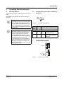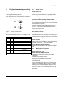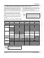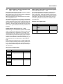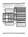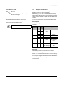
1
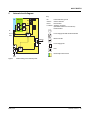
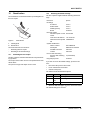
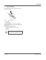
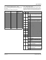
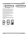
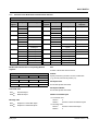
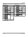
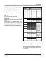
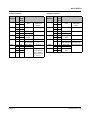
AXL F BK ETH Axioline F bus coupler for Ethernet Data sheet 8515_en_06 1 © PHOENIX CONTACT 2014-05-14 Description Valid from firmware version 1.10. Ethernet features The bus coupler represents the link between an Ethernet network (Modbus/TCP) and the Axioline F system. – – – You can connect up to 63 Axioline F devices to an existing Ethernet system with the help of the bus coupler. – – – 2 Ethernet ports (with integrated switch) Transmission speed of 10 Mbps and 100 Mbps Rotary coding switches for setting the IP address assignment and other functions Modbus/TCP (UDP) support BootP and DHCP Firmware can be updated Features of Axioline F – – – – Up to 63 additional Axioline F devices can be connected Runtime in the bus coupler is negligible (almost 0 µs) (for Modbus/UDP) Typical cycle time of the Axioline F local bus is around 10 μs Diagnostic and status indicators NOTE: In the event of a connection abort, outputs retain their last state By default upon delivery, the process data watchdog is deactivated. Observe the specifications in “Monitoring”. This data sheet is only valid in association with the UM EN AXL F SYS INST user manual. Make sure you always use the latest documentation. It can be downloaded from the product at phoenixcontact.net/products. AXL F BK ETH 2 Table of contents 1 Description .............................................................................................................................. 1 2 Table of contents ..................................................................................................................... 2 3 Ordering data .......................................................................................................................... 3 4 Technical data ......................................................................................................................... 4 5 Internal circuit diagram ............................................................................................................ 6 6 Connecting Ethernet and supply.............................................................................................. 7 7 Connection example................................................................................................................ 7 8 Configuration via rotary encoding switch ................................................................................. 8 9 Local status and diagnostic indicators ................................................................................... 11 10 Reset button .......................................................................................................................... 13 11 Service interface.................................................................................................................... 14 12 Startup behavior of the bus coupler ....................................................................................... 15 13 Monitoring.............................................................................................................................. 16 14 Monitoring of communications power UL (UL-Monitor).......................................................... 17 15 Substitute value behavior ...................................................................................................... 17 16 Modbus protocols and registers ............................................................................................ 17 17 Access to PDI objects............................................................................................................ 23 18 Simple Network Management Protocol - SNMP .................................................................... 31 19 WBM - Web-based management .......................................................................................... 31 20 Firmware update.................................................................................................................... 31 8515_en_06 PHOENIX CONTACT 2 AXL F BK ETH 3 Ordering data Description Type Order No. Pcs. / Pkt. Axioline F bus coupler for Ethernet (including bus base module and connectors) AXL F BK ETH 2688459 1 Accessories Type Order No. Pcs. / Pkt. Axioline F bus base module for housing type BK (Replacement item) AXL BS BK 2701422 5 Axioline F short power connector (for e.g., AXL F BK ...) (Replacement item) AXL CN S/UL 2701421 5 RJ45 connector, shielded, with bend protection sleeve, 2 pieces, gray for straight cables, for assembly on site. For connections that are not crossed, it is recommended that you use the connector set with gray bend protection sleeve. (Connector/Adapter) FL PLUG RJ45 GR/2 2744856 1 RJ45 connector, shielded, with bend protection sleeve, 2 pieces, green for crossed cables, for assembly on site. For connections that are crossed, it is recommended that the connector set with green bend protection sleeves is used. (Connector/Adapter) FL PLUG RJ45 GN/2 2744571 1 CAT5-SF/UTP cable (J-02YS(ST)C HP 2 x 2 x 24 AWG), heavy-duty instal- FL CAT5 HEAVY lation cable, 2 x 2 x 0.22 mm², solid conductor, shielded, outer sheath: 7.8 mm diameter, inner sheath: 5.75 mm ± 0.15 mm diameter (Cable/conductor) 2744814 1 CAT5-SF/UTP cable (J-LI02YS(ST)C H 2 x 2 x 26 AWG), light-duty, flexible installation cable 2 x 2 x 0.14 mm², stranded, shielded, outer sheath: 5.75 mm ± 0.15 mm diameter (Cable/conductor) FL CAT5 FLEX 2744830 1 Crimping pliers, for assembling the RJ45 plugs FL PLUG RJ45..., for assembly on site (Tools) FL CRIMPTOOL 2744869 1 Zack marker strip for Axioline F (device labeling), in 2 x 20.3 mm pitch, un- ZB 20,3 AXL UNPRINTED printed, 25-section, for individual labeling with B-STIFT 0.8, X-PEN, or CMS-P1-PLOTTER (Marking) 0829579 25 Zack marker strip, flat, in 10 mm pitch, unprinted, 10-section, for individual labeling with M-PEN 0,8, X-PEN, or CMS-P1-PLOTTER (Marking) ZBF 10/5,8 AXL UNPRINTED 0829580 50 Insert label, Roll, white, Unlabeled, can be labeled with: THERMOMARK ROLL, THERMOMARK X, THERMOMARK S1.1, Mounting type: snapped into marker carrier, Lettering field: 35 x 18.7 mm (Marking) EMT (35X18,7)R 0801831 1 Documentation Type Order No. Pcs. / Pkt. Application note, English, Starting up the AXL F BK ETH ... bus coupler AH EN AXL F BK ETH ... - - User manual, English, Axioline F: System and installation UM EN AXL F SYS INST - - User manual, English, Axioline F: Diagnostic registers, and error messages UM EN AXL F SYS DIAG - - Application note, English, Handling an Axioline station under Startup+ UM QS EN STARTUP+ - - Application note, English, Updating the firmware of an Axioline F bus coupler AH EN TFTP FIRMWARE UPDATE AXL F BK - - 8515_en_06 PHOENIX CONTACT 3 AXL F BK ETH 4 Technical data Dimensions (nominal sizes in mm) 122,4 74 Width 125,9 45 45 mm Height 125.9 mm Depth 74 mm Note on dimensions The depth is valid when a TH 35-7.5 DIN rail is used (according to EN 60715). General data Color traffic grey A RAL 7042 Weight 177 g (with connector and bus base module) Ambient temperature (operation) -25 °C ... 60 °C (Mounting position: wall mounting on horizontal DIN rail) Ambient temperature (operation) -25 °C ... 55 °C (Mounting position: any) Ambient temperature (storage/transport) -40 °C ... 85 °C Permissible humidity (operation) 5 % ... 95 % (non-condensing) Permissible humidity (storage/transport) 5 % ... 95 % (non-condensing) Air pressure (operation) 70 kPa ... 106 kPa (up to 3000 m above sea level) Air pressure (storage/transport) 70 kPa ... 106 kPa (up to 3000 m above sea level) Degree of protection IP20 Protection class III, IEC 61140, EN 61140, VDE 0140-1 Mounting position Any (observe temperature derating) Connection data Designation Axioline F connector Connection method Push-in technology Conductor cross section solid / stranded 0.2 mm² ... 1.5 mm² / 0.2 mm² ... 1.5 mm² Conductor cross section [AWG] 24 ... 16 Interface Ethernet Number 2 Connection method RJ45 socket, auto negotiation and autocrossing Transmission speed 10/100 MBit/s (Half or full duplex mode (automatic detection, can be adjusted manually)) Transmission physics Ethernet in RJ45 twisted pair Transmission length max. 100 m 8515_en_06 PHOENIX CONTACT 4 AXL F BK ETH Interface Axioline F local bus Connection method Bus base module Transmission speed 100 MBit/s Interface Service Number 1 Connection method Micro USB type B System limits Number of supported devices max. 63 (per station) NOTE: Electronics may be damaged when overloaded Observe the logic current consumption of each device when configuring an Axioline F station. It is specified in every module-specific data sheet. The current consumption can differ depending on the individual module. The permissible number of devices that can be connected therefore depends on the specific station structure. Protocols supported Protocols supported Modbus/TCP (UDP), SNMP, HTTP, BootP, DHCP, FTP, TFTP Supply of the bus coupler Supply of communications power UL 24 V DC Maximum permissible voltage range 19.2 V DC ... 30 V DC (including all tolerances, including ripple) Current supply at UBus 2A Current consumption from UL typ. 105 mA (without I/Os and UL = 24 V) max. 583 mA (with 2 A at UBus for the I/Os and UL = 24 V) Power consumption at UL typ. 2.5 W (without I/Os) max. 14 W (with 2 A load at UBus for the I/Os) NOTE: Electronics may be damaged when overloaded Provide external fuses for the 24 V UL area. The power supply unit must be able to supply four times the nominal current of the external fuse to ensure that it blows in the event of an error. Error messages to the higher level control or computer system None Mechanical tests Vibration resistance in acc. with EN 60068-2-6/IEC 60068-2-6 5g Shock in acc. with EN 60068-2-27/IEC 60068-2-27 30 g Continuous shock according to EN 60068-2-27/IEC 60068-2-27 10 g Conformance with EMC Directive 2004/108/EC Noise immunity test in accordance with EN 61000-6-2 Electrostatic discharge (ESD) EN 61000-4-2/IEC 61000-4-2 Criterion B; 6 kV contact discharge, 8 kV air discharge Electromagnetic fields EN 61000-4-3/IEC 61000-4-3 Criterion A; Field intensity: 10 V/m Fast transients (burst) EN 61000-4-4/IEC 61000-4-4 Criterion B, 2 kV Transient surge voltage (surge) EN 61000-4-5/IEC 61000-4-5 Criterion B; DC supply lines: ±0.5 kV/±0.5 kV (symmetrical/asymmetrical); fieldbus cable shield: ±1 kV Conducted interference EN 61000-4-6/IEC 61000-4-6 Criterion A; Test voltage 10 V Noise emission test according to EN 61000-6-3 Radio interference properties EN 55022 Class B Approvals For the latest approvals, please visit phoenixcontact.net/products. 8515_en_06 PHOENIX CONTACT 5 AXL F BK ETH 5 Internal circuit diagram Key: NET FE Ethernet RDY FE Service Reset Local bus CO PP RJ45 D 5V E RJ45 3.3V Functional earth ground Service interface Reset button Axioline F local bus (hereinafter referred to as local bus) RJ45 interface RJ45 FE Service Power supply unit with electrical isolation C Reset Local bus UBus Microcontroller µC Power supply unit XXX UL 3.3 V UBus XXX LED 24 V Electrically isolated areas UL 24 V Figure 1 8515_en_06 Internal wiring of the terminal points PHOENIX CONTACT 6 AXL F BK ETH 6 Connecting Ethernet and supply 6.1 Connecting Ethernet 6.2 Connect Ethernet to the bus coupler via an 8-pos. RJ45 connector. Connecting the supply voltage - terminal point assignment The Ethernet connections are set to autocrossing (auto crossover). Shielding The shielding ground of the connected twisted pair cables is electrically connected with the socket. When connecting network segments, avoid ground loops, potential transfers, and voltage equalization currents via the braided shield. Observe bending radii The housing dimensions specified under "Dimensions" refer to the bus coupler with I/O connectors without Ethernet connection. When installing the bus coupler in a control box, observe the bending radii of the Ethernet cables and the connectors used (e.g., FL CAT5 FLEX: 30 mm for fixed installation and FL CAT5 HEAVY: 30 mm without outer sheath and 45 mm with outer sheath). If required, use angled RJ45 connectors to maintain these bending radii. a1 a2 Figure 2 a1 b1 a2 b2 b1 b2 Terminal point assignment Termi- Color Assignment nal point Supply voltage input a1, a2 Red 24 V DC Supply of the logic voltage (internally jumpered) (UL) b1, b2 Blue GND Reference potential of the supply voltage (internally jumpered) 7 Connection example Ethernet NET CO PP RDY D E 12 14 0 2 4 6 S1 8 10 X10 UL 8515_en_06 CD AB 0 2 89 Figure 3 S2 4 6 24 V DC + (UL) EF X1 Ethernet Connection of the cables PHOENIX CONTACT 7 AXL F BK ETH 8 Configuration via rotary encoding switch You can configure the address assignment and other functions using rotary encoding switches. After modifying the switch position, restart the bus coupler, as the modification to the switch position does not take effect during operation. 14 S1 0 2 12 10 S2 Remote access Switch position 00 At this switch position, it is possible to remotely configure the device using corresponding tools (e.g., Startup+, webbased management (WBM)). Behavior during initial startup, after resetting the IP parameters or after resetting to default settings Default: BootP activated, DHCP deactivated 4 8 A valid IP address is not assigned (0.0.0.0) and communication is therefore not possible. 6 x10 E D C B A 8.1 F 0 The device transmits continuous BootP requests (2 s, 4 s, 8 s, 2 s ...), until a valid IP address has been received. 2 4 9 8 6 Valid IP parameters are then automatically saved as configuration data on the device. x1 Figure 4 Rotary encoding switch The code results from the sum of S1 x 10 plus S2 x 1. The image shows code 77 (7 x 10 + 7). S1 0 0 ... 5 5 ... 15 0 0 1 1 12 S2 Code Function 0 00 Remote access (default) 1 ... 0 01 ... 50 Manual address assignment 0 ... 9 51 ... 159 DHCP name assignment A 0A Fixed address E 0E Resetting IP parameters A 1A Activate connector and play mode B 1B Deactivate connector and play mode C 12C Resetting to the default settings Other Reserved Each additional startup BootP activated Three BootP requests are transmitted even in the case of a valid configuration. If the device receives a BootP reply, the new IP parameters are applied. Otherwise the device starts with the last valid configuration. DHCP activated For behavior, see switch position 51 ... 159. The station name can be selected in WBM, the default station name is the MAC address with "-" used as the separator. Static (BootP and DHCP deactivated) The device starts with the last valid assigned IP configuration. 8.2 Manual address assignment Switch position 01 ... 50 BootP deactivated, DHCP activated The first three octets in the IP address are preset as 192.168.0.x. The subnet mask is 255.255.255.0. Specify the last byte with the switch position. As such, you can select IP addresses between 192.168.0.1 and 192.168.0.50. Prior to transferring the IP address, a test is performed to check for any potential IP address conflicts. If a conflict is detected, the bus coupler temporarily switches the IP address to 0.0.0.0 (no IP communication). In this case, the NET LED flashes red. Eliminate the conflict and restart the bus coupler. 8515_en_06 PHOENIX CONTACT 8 AXL F BK ETH 8.3 DHCP name assignment Switch position 51 ... 159 This switch position is used to easily specify the DHCP host name for the device. The host name is provided to the DHCP server via DHCP options. This is therefore able to send a DNS update to the DNS server. 8.4 Fixed address Switch position 0A Behavior during initial startup, after resetting the IP parameters or after resetting to default settings A valid IP address is not assigned (0.0.0.0) and communication is therefore not possible. The DNS name consists of one set part, which is based on the order designation, and a variable part, which is determined by the switch position. Assign an address initially with another switch position. The first part of the station name is AXL-F-BK-ETH-. After a voltage reset, the device maintains the IP address which was assigned last. The set number is added. Each additional startup This results in the following station names: AXL-F-BK-ETH-051 ... AXL-F-BK-ETH-159. With this switch position, modifying the IP address via tools or web-based management is not possible. Behavior during initial startup, after resetting the IP parameters or after resetting to default settings A valid IP address is not assigned (0.0.0.0) and communication is therefore not possible. The device transmits continuous DHCP discover messages until a valid IP address has been received. Each additional startup Within the first minute, DHCP requests are transmitted with the last valid IP address. Three cases are possible: 1. The DHCP server accepts the desired address. The device starts with this IP address. 2. The DHCP server assigns a new IP address. The device applies the new IP parameters. 3. The DHCP server does not respond. The device transmits continuous DHCP Discover messages until new IP parameters have been received. 8515_en_06 8.5 Resetting IP parameters Switch position 0E The IP parameters stored on the device are reset. All other settings made on the device are retained. – BootP is activated for switch position 00. – IP address, subnet mask: 0.0.0.0 As long as the switch position 0E remains selected, no connection to the device can be established. IP communication is deactivated (LED NET static yellow). PHOENIX CONTACT 9 AXL F BK ETH 8.6 Plug and play mode Switch position 1A: activate connector and play mode Switch position 1B: deactivate connector and play mode Plug and play mode enables local bus modules connected in the field to be started up using the bus coupler without a higher-level computer (engineering system). If connector and play mode is enabled, the writing of process data is rejected. Read access to process data is possible. If connector and play mode is disabled, the bus is only started up if the configuration of the connected bus matches the saved configuration. See also section “Startup behavior of the bus coupler”. 8.7 Resetting to the default settings Switch position 12C All settings are reset to default settings, including IP parameters. The device is ready for operation after powering up, as soon as the RDY LED lights up green. A connection to the device however cannot be established in this switch position. As soon as the RDY LED lights up green, a new switch position can be selected on the rotary encoding switch and the device can be restarted. Alternatively, the default setting can also be restored via the reset button (see “Reset button”). 8.8 Reserved/invalid switch position The device starts with the previous settings, e.g., with the settings that were valid before the device was restarted. An invalid switch position is indicated by the RDY LED (red on). 8515_en_06 PHOENIX CONTACT 10 AXL F BK ETH 9 Local status and diagnostic indicators NET CO PP D E UL Figure 5 Local status and diagnostic indicators Designation UL NET CO RDY Color Meaning Green ULogic State ON OFF Green/ Network status Green ON yellow/ Green red flashing Yellow ON Yellow flashing Red ON Yellow/ red Configuration Red flashing OFF Yellow ON Red ON OFF PP Yellow Plug and Play mode RDY Green/ Ready yellow/ red 8515_en_06 ON OFF Green ON Flashing green/yellow Yellow ON Yellow flashing Flashing yellow/red Red ON OFF Description Communications power supply present. Communications power supply not present. At least one connection has been established to the device. A connection can be established to the device. IP configuration (IP address) is invalid (0.0.0.0). BootP requests or DHCP requests/discover messages are being transmitted. Network error; the process data watchdog was activated, the substitute value behavior of the outputs is performed. An IP address conflict has occurred during static configuration via rotary coding switches (IP address assigned twice). Device is not ready to operate. The startup parameterization is faulty. The active configuration of the local bus differs from the saved configuration. The active configuration of the local bus matches the saved configuration. Plug and play mode is activated. Plug and play mode is deactivated. Device is ready for operation. Communications power undervoltage or surge voltage Overtemperature Firmware/bus coupler is booting Firmware update is being performed. Firmware update has failed. Rotary encoding switches are set to an invalid/reserved position Device is not ready to operate. PHOENIX CONTACT 11 AXL F BK ETH Designation D E LNK 1/2 ACT 1/2 8515_en_06 Color Meaning Green/ Diagnostics yellow/ red State Description Green ON Run: Data exchange; status and data from the higher-level system is transmitted. Green Active: configuration is active, data exchange with invalid process flashing data, PDI channel can be used. Yellow ON Ready: Device is ready to operate, no data is exchanged. Yellow Access from Startup+ in I/O check mode flashing Flashing Bus error during active I/O check yellow/red Red flash- Local bus error on startup ing Red ON General local bus error Communication error Local bus device has been removed or configured device is missing. Reset at a local bus device Serious device error at a local bus device (local bus device can no longer be reached) YelError Yellow ON I/O warning at a local bus device low/ Red ON I/O error at a local bus device red OFF No I/O messages present. Green Link port 1/2 ON Connection via Ethernet to a module via port 1/2 established OFF No connection established via port 1/2 Yellow Activity port 1/2 ON Transmission or reception of Ethernet telegrams at port 1/2 OFF No transmission or reception of Ethernet telegrams at port 1/2 PHOENIX CONTACT 12 AXL F BK ETH 10 10.2 Reset button The reset button is located beneath the top marking label on the bus coupler. 1 2 Figure 6 1 2 Reset button Labeling field Reset button The reset button has two functions: – Restarting the bus coupler – Resetting of the default settings 10.1 Restarting the bus coupler The bus coupler is restarted when the button is pressed during operation. The outputs of the station are set to the parameterized substitute values. The process image of the inputs is not re-read. Restoring the default settings The bus coupler is supplied with the following default settings: Password IP settings IP address Subnet mask Default gateway BootP Firmware update Firmware update on next restart TFTP server IP address Name of firmware update file System identification Name of device Description Installation location Contact Process data monitoring Process data watchdog timeout Plug and play mode private 0.0.0.0 0.0.0.0 0.0.0.0 activated deactivated 172.16.40.201 c2688459.fw AXL F BK ETH Ethernet bus terminal Unknown Unknown 0 (deactivated) activated If you wish to restore the default settings, proceed as follows: • Disconnect the power to the module. • Press and hold the reset button. • Switch on the power. The LEDs indicate the initialization phase: LED RDY RDY RDY • State OFF Yellow ON Green Meaning Starting firmware Initializing firmware Initialization complete When the RDY LED lights up green, release the button. The default settings are restored. 8515_en_06 PHOENIX CONTACT 13 AXL F BK ETH 11 Service interface The service interface is located beneath the top marking field on the bus coupler. 1 2 Figure 7 1 2 Service interface Labeling field Service interface You can connect the bus coupler to a PC on which the Startup+ startup/diagnostic tool is running via USB using the service interface. Startup+ offers the following functions: – Parameterization of the station I/O modules – I/O check – Diagnostics For detailed information on Startup+, please refer to the UM QS EN STARTUP+ user manual. 8515_en_06 PHOENIX CONTACT 14 AXL F BK ETH 12 Startup behavior of the bus coupler 12.1 Plug and play mode Plug and play mode active The bus coupler supports connector and play mode. Plug and play mode enables local bus modules connected in the field to be started up using the bus coupler without a higher-level computer (engineering system). The connector and play mode status (active or inactive) is stored retentively on the bus coupler. The current mode is displayed via the PP LED. In connector and play mode, the connected local bus modules are detected and their function checked. If this physical configuration is ready to operate, it is started, however writing outputs is not enabled. To enable writing outputs, connector and play mode must be deactivated. The deactivation is to be saved at the same time as saving the signal, active configuration, and reference configuration. 12.2 Startup parameterization There are Axioline F modules that can be parameterized (e.g., measuring ranges, substitute value behavior in the event of a bus error). These modules can be parameterized via Startup+ or via the PDI channel (see also “Access to PDI objects”). The parameterization is stored retentively on the I/O modules, which is why this information only has to be written once on system startup. When connector and play mode is deactivated, the bus coupler checks the parameterization of the I/O modules as well as the bus configuration. After the bus configuration has been changed (e.g., module replacement), the bus coupler prevents process data from being written, bit 3 is set in the status register (7996), and the LED CO lights up yellow. Modify the parameterization as appropriate and acknowledge this with code 0008hex in the command register (2006). The bus coupler will then enable the output of process data. Plug and play mode inactive When connector and play mode is deactivated, the reference configuration is compared to the physical configuration. If they are the same, the bus coupler is set to the RUN state on the first write access. If the reference configuration and the physical configuration differ, the CO LED lights up red and process data exchange is no longer possible for safety reasons. In order to operate the bus despite this, you have the following two options: 1. Restore the original configuration so that the reference configuration and the physical configuration are the same again. 2. Activate connector and play mode and restart the bus coupler so that the active physical configuration is accepted as the reference configuration. 8515_en_06 PHOENIX CONTACT 15 AXL F BK ETH 13 Monitoring Ethernet communication is monitored by a process data watchdog. The following actions are monitored: – Client application – Ethernet connection – Process data exchange If the timeout period expires for the activated process data watchdog, OUT process data is blocked. The parameterized substitute value behavior of I/O modules is performed. The error is indicated by the NET LED (red on). In this state (Net Fail), OUT process data can continue to be updated by the application. Following a Net Fail reset, substitute values are then replaced by the latest process data. Net fail If there is no triggering during the timeout period, an error occurred. Two responses follow: – All outputs are set to the configured substitute value. – The Net Fail signal is set (NET LED is red and bit 1 in status register 7996 is set). For safety reasons, the user cannot stop the watchdog once it has been activated. If the user terminates the controlling application, there is no watchdog triggering; when the timeout period elapses, the Net Fail signal is set and the parameterized substitute value behavior is executed. After the watchdog has performed its task, the outputs are only enabled again after acknowledgment. Acknowledge error message NOTE: In the event of a connection abort, outputs retain their last state The process data watchdog is deactivated by default. To reset the error, it must be acknowledged. The following options are available: – Web-based management – Modbus register 2006 Activate the process data watchdog before starting up an application. When the error is acknowledged, the watchdog is restarted. This means that it must be triggered during the timeout period, otherwise an error is detected again. Function of the process data watchdog If station outputs are set, the controlling process must be able to access the station. In the event of an error, e.g., network line interrupted or function error in the controlling process, the bus coupler can respond appropriately via the process data watchdog. When activating the process data watchdog, it is started by the first write process and the next write process is expected within the timeout period. During error-free operation, the write process is performed during the timeout period and the watchdog is restarted (triggered). Configuring the process data watchdog • • To activate the watchdog, specify the desired timeout value in the range between 200 ms and 65000 ms. To deactivate the watchdog, specify the value 0. You have the following options for changing the timeout period: – Web-based management – Modbus register 2000 Reading calls do not trigger the process data watchdog. 8515_en_06 PHOENIX CONTACT 16 AXL F BK ETH 14 Monitoring of communications power UL (UL-Monitor) A monitoring function monitors the supply of communications power UL. If the value is outside the specified voltage range, this is indicated in status register 7996. Undervoltage Bit 12 Bit 14 Surge voltage Bit 13 Bit 15 16 The bus coupler supports a Modbus/TCP server and a Modbus/UDP server. The Modbus protocol can be used in both in a connectionrelated (TCP) and wireless (UDP) manner. 16.1 Set as long as the communications power is too low. Still set after a brief undervoltage. Set as long as the communications power is too high. Still set after a brief surge voltage. Modbus connections The bus coupler supports up to eight Modbus/TCP connections simultaneously. The connection can access different addresses simultaneously. Since eight connections are supported, a connection can quickly be restored. This means that the client can successfully restore an interrupted Modbus connection. The UDP server is wireless. Very brief voltage disturbances are also registered with bits 14 and 15. Both bits remain set until the UL-Monitor has been acknowledged with code 0080hex via command register 2006. 15 Modbus protocols and registers In applications with high demands on the response time, it is recommended that Modbus/ UDP is used to access the process data. In this case, the runtime in the bus coupler is negligible (just a few μs). Substitute value behavior If Ethernet communication fails or an error occurs in the local bus, all outputs of the station are set to the substitute values previously parameterized on the module. 16.2 In order to do this, plug and play mode must be deactivated and the process data watchdog must be activated. 16.3 For the possible substitute values of a module, please refer to the relevant module-specific data sheet. 8515_en_06 Modbus conformance classes The bus coupler supports Modbus conformance class 0. Modbus function codes The following function codes are supported: Function Function code FC3 Read holding registers FC4 Read input registers FC6 Write single registers FC16 Write multiple registers FC23 Read/write multiple registers Description Read words from outputs and inputs Read words from inputs Write word for output data Write several output words Read and write several process data for inputs and outputs PHOENIX CONTACT 17 AXL F BK ETH 16.4 Modbus register Modbus register table (16-bit word) Local bus 1400 1401 ... 1649 Access Function 1700 1701 ... 1763 R R 1800 1801 ... 1989 R R Special register 2000 2006 2075 ... 2089 PDI 6010 ... 6089 6210 ... 6289 Diagnostics 7996 7997 7998 7999 Process data 8000 ... 8999 9000 ... 9999 R W R R Access with function code Number of local bus devices/entries FC3, FC4 Device type of local bus devices (4 registers per device) Number of local bus devices/entries Number of process data registers (8xxx or 9xxx) for local bus devices (1 register per device) Number of local bus devices/entries I/O diagnostics of local bus devices (3 registers per device) R/W W R Timeout for process data watchdog Command register Electronic rating plate FC3, FC4, FC6, FC16 FC6, FC16 FC3, FC4 R/W R Tunnel register for PDI requests (channel 1 ... 8) FC3, FC4, FC6, FC16, FC23 Tunnel register for PDI confirmations (channel 1 FC3, FC4, FC23 ... 8) R R R R Status register Diagnostic status register Diagnostic parameter register 1 Diagnostic parameter register 2 R R/W Input process data Output process data FC3, FC4, FC23 FC3, FC4, FC6, FC16, FC23 Read Write In write access to the Modbus/TCP clients on the “Read only” register, the data is not transferred and is answered with exception code 02. 8515_en_06 PHOENIX CONTACT 18 AXL F BK ETH 16.5 Figure showing process data on Modbus registers (8000 ... 8999, 9000 ... 9999) The process data of the modules connected to the bus coupler are mapped in one register range. The registers are assigned in the same way for all function codes, they are not differentiated according to the data types implicated in the function codes (e.g. Modbus register and Modbus input register). A number of registers is assigned to each module according to the data width. Each register comprises 16 bits. A module with a data width of 8 bits is mapped on one register, a module with 32 bits is mapped on two registers. No differentiation is made between digital and analog modules. For address assignment, all IN process data of the connected modules is mapped according to the physical bus configuration from Modbus register 8000 (up to 8999, maximum). All OUT process data is mapped according to the physical bus configuration from Modbus register 9000 (up to 9999, maximum). The current mapping of process data to the Modbus register for the I/O modules connected to the bus coupler can be viewed via the web-based management for the bus coupler under “Information, Modbus I/O table”. Example: figure of process data on the Modbus register AXL F BK ETH AXL DI 16/4 AXL DI 16/4 8000 AXL AO 8 AXL DI 32/1 8001 8002 ... 8008 8009 8010 AXL DO 8/2-2A 8011 AXL AI 8 8012 ... 8019 8020 ... 8033 ... 8999 AXL CNT 2/ INC 2 AXL AO 8 Example of a station AXL DI 32/1 AXL DO 8/2-2A Input process data Byte 0 Byte 1 Channel 8 ... 1 Channel 16 ... 9 IN1 IN2 ... IN8 Byte 0 Byte 1 Channel 8 ... 1 Channel 16 ... 9 Byte 2 Byte 3 Channel 24 ... Channel 32 ... 17 25 IN1 ... IN8 Word 0 ... Word 13 Reserved Reserved 9000 AXL AI 8 AXL CNT 2/ INC 2 Output process data - - 9001 9002 ... 9008 9009 OUT1 OUT2 ... ... - - 9010 - - 9011 - 9012 ... 9019 9020 ... 9033 ... 9999 - Byte 0 Channel 8 ... 1 ... - Word 0 ... Word 13 Reserved Reserved For further information on the assignment of bytes and words, please refer to the modulespecific documentation (data sheet, user manual). 8515_en_06 PHOENIX CONTACT 19 AXL F BK ETH 16.6 Register tables for the bus configuration frame (1401 ... 1649 / 1701 ... 1763) Register table for the number of process data registers for local bus devices (1701 ... 1763) Both register tables map the currently loaded bus configuration frame of the connected devices. When plug and play mode is activated, the bus configuration frame that is physically present is sent. When plug and play mode is deactivated, the stored reference configuration is sent. Any differences between the stored reference configuration and the bus configuration that is physically present are indicated by diagnostic registers 7997 to 7999. The register tables can be used to monitor the bus configuration in the user application. The entire table can always be read, the “Number of entries” register indicates how many entries there actually are. This register table indicates the number of registers in the process data register tables occupied by each device (80008999, 90009999). This information can be used to dynamically adapt the user application to changes in the bus configuration. The offset for the relevant device in the process data register table can therefore be calculated in the user application. Structure of the register table Index 1700 1701 Register table for DeviceType (1401 ... 1649) The DeviceType is a manufacturer-specific module identification. It can be used to replace and operate modules of the same type within a bus configuration. For example, a 16channel output module with screw connection technology can be replaced by a module with spring-cage connection technology even though it does not have the same order number. On the other hand, a different functionality (e.g., 32 channels instead of 16) is indicated by a different DeviceType. In this case the DeviceType acts as a uniquely assigned ID, but the module functionality cannot be directly derived from it (e.g., by evaluating a specific bit). Should this be necessary, use the relevant PDI objects for this (see module-specific data sheet). ... 1763 Contents Number of entries Number of process data registers ... Number of process data registers 1 ... 63 1st device ... 63rd device Structure of the register table Index 1400 1401 1402 1403 1404 ... 1646 1647 1648 1649 8515_en_06 Contents Number of entries DeviceType 1 ... 63 1st device ... DeviceType ... 63rd device PHOENIX CONTACT 20 AXL F BK ETH 16.7 Register for I/O diagnostics (1800 ... 1989) The register table shows the error number, priority, channel/ group/module, and error code information contained in diagnostic object 0018hex for every device. For every device, the first message is displayed with the highest priority. You can view the entire table at any time. This table should not be read cyclically. Bits 0 and 1 in diagnostic status register 7997 indicate that an error message is present. This register can be read cyclically together with the process data. If either of these bits is set, read the registers for I/O diagnostics acyclically. Modbus register 1800 Device 1801 1802 1. 1803 ... 1987 1988 1989 1 ... 63 ... 63rd High byte Number of valid entries (number of devices) Error number Priority Channel/ group/module Error code ... ... Error number Priority Channel/ group/module Error code Command register (2006) The bus coupler behavior can be controlled via the command register. Only write access is enabled for the register. In the event of invalid requests (codes that are not supported), an error message is returned. Code (hex) 0000 0001 0002 0008 Low byte For details of the contents of the fields for error number, priority, channel/group/module, and error code from PDI object 0018hex, please refer to the module-specific documentation (data sheet, user manual). 8515_en_06 16.8 0010 0020 0080 0400 0800 8F00 8F01 Meaning No action Switch on connector and play mode applied only following restart Switch off connector and play mode applied immediately Acknowledge startup parameterization applied immediately, parameterization is permanently acknowledged, i.e. successful restart does not result in another message Set Net Fail Acknowledge Net Fail Reset UL-Monitor (see “Monitoring of communications power UL”) Activate hardware acceleration for Modbus/UDP applied only following restart Deactivate hardware acceleration for Modbus/ UDP applied only following restart Restart bus coupler Read parameter file again (config.svc) When commands 8F00hex and 8F01hex are being executed, the substitute value behavior of the outputs is active. The hardware acceleration for Modbus/UDP shortens the processing time of Modbus/UDP requests. It is enabled by default. In the event of compatibility problems, deactivate the hardware acceleration with code 0800hex in the command register and perform a restart. This setting is stored retentively. PHOENIX CONTACT 21 AXL F BK ETH 16.9 Electronic rating plate (2075 ... 2089) The electronic rating plate contains the basic information on the module. Only read access is enabled to the registers. Modbus register 2075 2076 2077 2078 2079 2080 2081 2082 2083 2084 2085 2086 2087 2088 2089 Maximum length of the register Name of device 125 Description 125 Installation location 125 Contact 125 Boot loader version 4 Firmware version 6 Firmware status 4 Hardware version 2 Firmware date 4 Hardware date 4 Serial number 10 MAC address 9 Order No. 10 Order designation 15 Manufacturer 10 name 16.10 Status register (7996) The status register indicates the status of the bus coupler. Each bit has a different meaning. Several bits can be set simultaneously. No bit is set in normal operation without errors. Function Bit 0 Code (hex) 0001 Meaning 1 0002 0 1 2 0004 0 1 3 0008 4 0010 5 0020 6 7 8 0040 0080 0100 9 0200 10 11 12 0400 0800 1000 0 1 0 1 0 1 0 1 0 1 0 1 13 2000 0 1 14 4000 0 1 15 8000 0 1 1 0 8515_en_06 An error occurred in the local bus (e.g., a bit in the diagnostic register is set) No error A Net Fail occurred, active substitute values No error Active bus configuration does not match the reference configuration No error Startup parameterization is faulty No error Plug and play mode is activated. Plug and play mode is deactivated. Startup not completed Startup completed Reserved Reserved Overtemperature of the power supply Normal temperature Overtemperature of the logic PCB Normal temperature Reserved Reserved UL-Monitor: communications power too low Voltage OK UL-Monitor: communications power too high Voltage OK UL-Monitor: communications power too low (acknowledge code 0080hex via register 2006) No error stored UL-Monitor: communications power too high (acknowledge code 0080hex via register 2006) No error stored PHOENIX CONTACT 22 AXL F BK ETH 16.11 Diagnostic status register (7997) 16.12 Diagnostic parameter register (7998, 7999) For the meaning of this register, please refer to the AXL F SYS DIAG user manual. 17 For the meaning of this register, please refer to the AXL F SYS DIAG user manual. Access to PDI objects PDI stands for parameter, diagnostics, and information. The PDI channel is used in addition to the process data channel in the Axioline F system for the demand-oriented, acyclic transmission of parameter and diagnostic data as well as other information. Each Axioline F device has this channel and can use it independently of the process data. Objects created in the Axioline F device can be accessed via the PDI channel using services. These objects can be used, for example, to set measuring ranges, to specify the substitute value behavior of outputs in the event of a bus error or to read diagnostic details. The objects are addressed via an object index (e.g., 0018hex: DiagState). For detailed information on the objects present on a module, please refer to the modulespecific documentation. You can access the PDI channel via Modbus/TCP as well as via Modbus/UDP. To this end, register sets are used, with which a tunnel method can be implemented. This method is explained below. Process data register Application 8000 ... 8999 9000 ... 9999 Modbus/TCP or Modbus/UDP I/O Process data 01010101010101 01010101010101 01010101010101 01010101010101 01010101010101 01010101010101 Objects PDI tunnel register 0019hex 6010 ... 6089 6210 ... 6289 Controller Figure 8 8515_en_06 Ethernet Bus coupler PDI channel 0018hex 0081hex 0080hex Axioline F local bus Axioline F I/O module Access to PDI objects PHOENIX CONTACT 23 AXL F BK ETH 17.1 Functional description Eight Modbus PDI channels are provided, which are to be assigned to the Modbus masters in the application without causing conflict. NOTE: Data loss Use an appropriate channel assignment to ensure that one channel is only ever used by one master. Each Modbus PDI channel features a request table and confirmation table. The data necessary for a PDI request (PDI read or PDI write) is written to the request table by means of Modbus write access (FC16/FC23). Subsequently, the PDI confirmation is read out of the confirmation table via Modbus read access (FC3, FC4, FC23). You can use the PDI service with Modbus function code FC23 very easily; access to the request and the confirmation table is possible with just one access. The confirmation table can only be accessed as read-only, whereas both read and write access are enabled for the request table. In the case of read-only access to the request table, the most recently written data is output (not the PDI confirmation). The 6xx5 data registers (e.g., 6015, 6215) have a “virtual length”. This means that data can be transmitted, as long as the maximum length of the Modbus telegram is not exceeded. The data is mapped internally onto the following registers (not directly), thereby ensuring a higher packing density of the PDI channels. Use a Modbus function code for access, which allow access to multiple registers in one request (FC3, FC16 or FC23). As such, the register, e.g., 6215 functions as a start address. Always use 125 as the register number when readaccessing a PDI object (PDI read). In the case of write access to a PDI object (PDI write), use the corresponding length. Please see the following examples. As such, read access to the confirmation table is granted with a specified length. The specified number of registers is always output. If the actual data length is lower (e.g., PDI object is smaller or contains a negative confirmation), all remaining registers are filled with “0000”. The actual length of the PDI object can be found in the field “Number of PDI data bytes”. If the actual length is longer, only the requested data is output. 8515_en_06 PHOENIX CONTACT 24 AXL F BK ETH 17.2 Structure of the Modbus PDI communication channels Modbus PDI communication channel 1 PDI confirmation Meaning Modbus Byte Positive response register Command code 6210 0 Message code 1 Slot 6211 2 Slot 3 Subslot 6212 4 Subslot Reserved 5 Reserved PDI object index 6213 6 PDI object index 7 Subindex 6214 8 Subindex 9 Number of PDI data Number of PDI data bytes bytes Data byte 0 6215 10 Error class Data byte 1 11 Error code Data byte 2 6216* 12 Data byte 0 Data byte 3 13 Data byte 1 Data byte 4 6217* 14 Data byte 2 Data byte 5 15 Data byte 3 ... ... ... ... PDI request Byte Modbus register 6010 0 1 2 3 4 5 6 7 8 9 6011 6012 6013 6014 6015 10 11 12 13 14 15 ... 6016* 6017* ... Modbus PDI channels and corresponding Modbus registers Modbus PDI communication channel 2 ... 8 PDI request 6010 ... 6015 6020 ... 6025 ... 6080 ... 6085 PDI confirmation 6210 ... 6215 6220 ... 6225 ... 6280 ... 6285 1 Command code Negative response Message code Slot Subslot Reserved PDI object index Subindex 0 Error class Error code Additional code Slot Position of the module in the local bus Subslot Specify a subslot if you wish to access a submodule (e.g., IO-Link). Not used at present (= 0). PDI object index See module-specific data sheet. PDI object subindex See module-specific data sheet. 0041hex 0042hex Read PDI object Write PDI object Message code 8041hex 8042hex 8515_en_06 Response to “Read PDI object” Response to “Write PDI object” Number of PDI data bytes For command code 0 0041hex 0042hex Amount of data to be written in bytes For message code Amount of data read in bytes 8041hex 8042hex 0 PHOENIX CONTACT 25 AXL F BK ETH Error class, error code 0000hex: No error 0000hex: An error has occurred; negative response ID of error message 17.3 Example: read PDI object The PDI read service can be conveniently used with the Modbus function code FC23 (read/write). Alternatively, you can use FC16 (write) and FC3 (read). Additional code The contents of the VendorID object (manufacturer identification) of the first module should be read after the first bus coupler. More detailed information about the error cause. To this end, PDI channel 1 (6010/6210) should be used. Should an error occur, the error message details the error class, error code, and additional code. Read request For the meaning of this error code, please refer to the AXL F SYS DIAG user manual. Write the following values via FC16 or FC23 to register 6010 onwards. Modbus Byte Conaddress tents (hex) 6010 0 00 1 41 6011 2 00 3 01 6012 4 00 5 00 6013 6 00 7 02 6014 8 9 00 00 Meaning Command code Read PDI object Slot 1st local bus device Subslot Reserved PDI object index No subslot Reserved 0002hex: VendorID (manufacturer identification) Subindex No subindex Number of Read, therefore PDI data bytes = 00 Response The result is provided in register 6210 and onwards. As described before, register 6215 has an internal “virtual length”. Use a Modbus function code for access to the registers marked with *, which allow access to multiple registers in one request. Register 6210 functions as the start address; 125 can always be used as the register number in the case of read access. 8515_en_06 PHOENIX CONTACT 26 AXL F BK ETH - Positive response Modbus Byte Conaddress tents (hex) 6210 0 80 1 41 6211 6212 6213 6214 6215 6216* 6217* 6218* 6219* 8515_en_06 2 3 4 5 6 7 8 9 00 01 00 00 00 02 00 07 10 11 12 13 14 15 16 17 18 19 00 00 30 30 41 30 34 35 00 00 – Negative response Meaning Message code Slot Subslot Reserved PDI object index Response to “Read PDI object” Copy of request Modbus Byte Conaddress tents (hex) 6210 0 80 1 41 6211 Copy of request 6212 Copy of request 6213 Subindex Copy of request Number of 7 bytes of data PDI data bytes read Error class No error Error code Read data 00A045 (7 bytes, including zero terminator; ASCII coded) 6214 6215 6216* 2 3 4 5 6 7 8 9 00 01 00 00 00 02 00 00 10 11 12 13 xx xx xx xx Meaning Message code Slot Subslot Reserved PDI object index Response to “Read PDI object” Copy of request Copy of request Copy of request Subindex Copy of request Number of Error message, PDI data bytes therefore = 0 Error class Error message Error code Additional code Top up to an even number of bytes PHOENIX CONTACT 27 AXL F BK ETH 17.4 Example: write to PDI object The PDI write service can be conveniently used with the Modbus function code FC23 (read/write). Alternatively, you can use FC16 (write) and FC3 (read). All process data channels of the AXL F AI4 I 1H module should be parameterized. In the physical bus configuration, the module is the second module. The parameterization is performed via the ParaTable object (0080hex). PDI channel 3 (6030/6230) should be used. Write request Modbus Byte Conaddress tents (hex) 6030 0 00 1 42 6031 2 00 3 02 6032 4 00 5 00 6033 6 00 7 80 6034 8 9 00 0C 6035 10 11 12 13 14 15 16 17 00 04 00 04 00 04 00 04 6039* 18 19 00 00 6040* 20 21 00 00 Write the following values via FC16 or FC23 to register 6030 onwards. As described before, register 6035 has an internal “virtual length”. Use a Modbus function code for access to the registers marked with *, which allow access to multiple registers in one request. Register 6030 functions as the start address; the total length must be specified as a register number. In the example, the total length is 11 (register 6030 to 6040). 6036* 6037* 6038* Meaning Command code Write PDI object Slot 2nd local bus device Subslot Reserved PDI object index No subslot Reserved 0080hex: ParaTable (parameter table) Subindex No subindex Number of 12 bytes (length PDI data bytes of the parameter table) Data byte 0 According to the Data byte 1 module-specific data sheet: Data byte 2 Data byte 3 For each of the Data byte 4 four channels: Data byte 5 Filter 30 Hz, Data byte 6 16-sample average value, Data byte 7 Measuring range 0 mA ... 20 mA Data byte 8 According to the Data byte 9 module-specific data sheet: Data format IB IL Data byte 10 According to the Data byte 11 module-specific data sheet: Reserved Response The result is provided in register 6230 onwards. As described before, register 6235 has an internal “virtual length”. Use a Modbus function code for access to the registers marked with *, which allow access to multiple registers in one request. Register 6230 functions as the start address; 125 can always be used as the register number in the case of read access. 8515_en_06 PHOENIX CONTACT 28 AXL F BK ETH - Positive response Modbus Byte Conaddress tents (hex) 6230 0 80 1 42 6231 6232 6233 6234 6235 6236* ... 8515_en_06 2 3 4 5 6 7 8 9 00 02 00 00 00 80 00 00 10 11 12 13 ... 00 00 00 00 00 – Negative response Meaning Message code Slot Subslot Reserved PDI object index Response to “Write PDI object” Copy of request Modbus Byte Conaddress tents (hex) 6230 0 80 1 42 6231 Copy of request 6232 Copy of request 6233 Subindex Copy of request Number of For write access PDI data bytes =0 Error class No error Error code PDI data Not available for write access to the confirmation, for this reason = 0 6234 6235 6236* 2 3 4 5 6 7 8 9 00 02 00 00 00 80 00 00 10 11 12 13 xx xx xx xx Meaning Message code Slot Subslot Reserved PDI object index Response to “Write PDI object” Copy of request Copy of request Copy of request Subindex Copy of request Number of Error message, PDI data bytes therefore = 0 Error class Error message Error code Additional code PHOENIX CONTACT 29 AXL F BK ETH 17.5 Exception Codes In order to increase user comfort, the main problems that can occur when accessing the PDI channel are indicated directly via a Modbus exception. In addition to the standard exception codes (01 ... 04; see Modbus specification), some user-defined exception codes have been defined specifically for PDI channel handling. Designation ILLEGAL_FUNCTION ILLEGAL_DATA_ADDRESS ILLEGAL_DATA_VALUE Exception Code dec hex 1 1 2 2 3 3 DEVICE_FAILURE 4 4 MBUS_PDI_ERR_DOUBLE_USE_CH 16 10 MBUS_PDI_ERR_ILLEGAL_SVC_CODE 17 11 MBUS_PDI_ERR_USER_PROBLEM 18 12 MBUS_PDI_ERR_INVALID_DATA 19 13 8515_en_06 Meaning/cause General General Write to data register (60x5) even though PDI read was selected in the “Service command code” field. PDI length (register 60x4; length of the data to be written in bytes) does not match the actual length. Internal failure (e.g., maximum number of connections exceeded) Device cannot be reached (timeout) An attempt was made to use the same communication channel with multiple TCP connections. An attempt was made to use a communication channel used with a TCP connection via UDP. The “Service code” field (register 60x0) does not contain a valid service code. 0041hex is valid for PDI_Read and 0042hex for PDI_Write. An error occurred on a PDI_Write request (triggered by writing to register 60x5). For additional information, refer to the confirmation (register 62xx). No valid confirmation that can be read via the confirmation table (register 62xx). In this case, an access attempt returns the specified exception. PHOENIX CONTACT 30 AXL F BK ETH 18 Simple Network Management Protocol - SNMP The bus coupler supports SNMP v1 and v2c. Management Information Base - MIB The corresponding latest MIBs are available on the Internet at phoenixcontact.net/products. For the object descriptions, please refer to the ASN1 descriptions for this product. The password for read access is “public” and cannot be changed. By default upon delivery, the password for write/read access is “private” and can be modified at any time. 19 WBM - Web-based management The device has a web server, which generates the required pages for web-based management and, depending on the requirements of the user, sends them to a standard web browser. Web-based management can be used to access static information (e.g., technical data, MAC address) or dynamic information (e.g., IP address, status information, local bus structure, and local bus diagnostics). Calling web-based management The device web server can be addressed using the IP address if configured accordingly. The homepage (web page) of the device is accessed by entering the URL “http://ip-address”. Example: http://172.16.113.38 The default password is “private”. If you cannot access the WBM pages, check the connection settings in your browser and deactivate the proxy, if set. 20 Firmware update In order to update the firmware of the bus coupler, provide the bus coupler with a firmware container via a TFTP server or load it onto the bus coupler via FTP. Any FTP client or TFTP server can be used for this, e.g., the Factory Manager. If the Factory Manager is not used, initialize the firmware update via web-based management. When carrying out the firmware update, the RDY LED flashes yellow. For detailed information on firmware update via TFTP, please refer to application note TFTP FIRMWARE UPDATE AXL F BK. 8515_en_06 PHOENIX CONTACT GmbH & Co. KG • 32823 Blomberg • Germany phoenixcontact.com 31