1
© Copyright October, 1996 Adept Technology, Inc.
ALL RIGHTS RESERVED
This material is the property of Adept Technology, Inc., and
contains confidential information. No part of this publication
may be reproduced, published, stored in a retrieval system, or
disclosed to others without prior written permission from
Adept Technology, Inc.
The use of general descriptive names, trade names,
trademarks, etc., in this manual, even if they are not especially
identified, does not mean that such names, as understood by
the Trade Marks and Merchandise Marks Act, may
accordingly be used freely by anyone.
The material contained herein is subject to change without
notice.
Table of Contents
CADDS Interface
Release Notes
Introduction
Installing the CADDS Converter
Using the CAD Interface Panel
Importing CADDS Parts into SILMA Software
Importing CADDS Assemblies into SILMA Software
Editing the Settings
Editing Resolution
Skipping Attributes
Editing Compaction
Exporting Models to CADDS
Supported Entities
CADDS to SILMA Software (Importing)
SILMA Software to CADDS (Exporting)
1
1
3
4
6
7
7
7
9
10
11
12
12
14
Catia Interface
Release Notes
Introduction
Using the CAD Interface Panel
Importing Models
Importing Large Export Files
Editing the Settings
Editing Resolution
Skipping Attributes
Editing Compaction
Exporting Models
Trouble Shooting
Supported Entities
(10/96)
15
15
17
19
20
21
22
23
24
25
27
27
i
Table of Contents
SLA Interface
Release Notes
Introduction
Using the CAD Interface Panel
Importing Models
Exporting Models
Notes on Working with SLA Files
29
29
30
32
33
34
Pro/ENGINEER Interface
Release Notes
Getting Started
Exporting Models
Trouble-Shooting
Supported Entities
Faces (Trimmed Surfaces)
Edges (Trimmed Surfaces Boundary Edges)
Supported GD&T Entities
35
37
38
39
40
40
40
41
VSA Interface
Release Notes
Getting Started
Exporting Models
Trouble Shooting
42
43
44
45
Appendix: Importing Large Models
ii
CAD Interfaces
CADDS Interface
CADDS Interface
Release Notes
Current Version
V 3.3
Module
CADDS_INTERFACE_3.3
Platform
HP, Sun, Solaris, SGI5
Introduction
The CADDS interface is a two-way translator: data transfer can be performed
in two ways:
■ CADDS part files can be translated into SILMA software
model files.
■ SILMA software models can be translated into CADDS part
files.
Both these operations can be performed on any platform the interface is
supported. It is not required to have CADDS running in order to perform any of
these operations.
The CADDS Translator user interface is a user-friendly, menu-driven interface.
“Using the CAD Interface Panel” on page 4 provides a detailed description of
how to use the SILMA software menus and panels.
(10/96)
1
Introduction
In the SILMA software CADDS interface, there are three major classes of
geometric models that can be directly translated from Computervision
CADDS4X and CADDS5X to SILMA software:
➢ Three-dimensional wireframe models
➢ Three-dimensional surface models
➢ Three-dimensional solid models
Using this interface, the SILMA software program reads the System A data
(CADDS), translates it into System B format (SILMA software), and writes it
into the System B database. System B can then translate and write data back to
System A and provide updates between the systems.
System B
SILMA software
read
System A
CADDS
write
updating
You can model parts in CADDS and simulate them in SILMA software—all
transparently. Your CAD parts geometry is automatically updated by a menudriven converter. A part may consist of any kind of CADDS geometry and
converted to NURBS geometry at the time of translation into SILMA software.
The SILMA software CADDS interface reads, writes, and updates CADDS part
models and SILMA software models. Use the interface to import CADDS
models into SILMA software and to export certain geometry and data generated
from simulation.
The interface lets you create CADDS parts (without even getting into CADDS)
by selecting the SILMA software geometry and assembly layout. You can then
export these parts to the CADDS system. The interface also interacts with the
CADDS runtime process to keep the translated parts up-to-date.
2
CAD Interfaces
CADDS Interface
Installing the CADDS Converter
If the CADDS converter is present during SILMA software installation,
the newuser script prints a message asking you to logout and login as
root to run install_cvdors. The newuser script then creates the links and
starts the daemons on your system (ODB-DAEMON if the assembly
interface is installed).
Several environmental variables are set as part of running the newuser
script at the SILMA software installation. The variables required for
cvdors_login are appended to the user’s .login file, and cvdorsrc is
copied to your user area and renamed .cvdorsrc. The uenv is copied
to your user area and renamed .uenv.
Global variables used in the CADDS converter are documented in
cadds_default.sil which exists in your product when you create a
product with the CADDS converter.
CADDS4X is not needed to convert CADDS parts to SILMA software
models. However, CADDS4X (including Assembly Design) is needed
if you want to convert Assembly Design models.
(10/96)
3
Using the CAD Interface Panel
Using the CAD Interface Panel
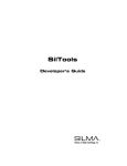
The CAD Interface panel is displayed by selecting Import/Export Model… from
the Modeling pulldown menu.
List of directories under the
current directory.
This section of the panel changes
depending on the Import/Export
toggle.
Importing files is explained in
“Importing CADDS Parts into
SILMA Software” on page 6.
Exporting models is explained in
“Exporting Models to CADDS” on
page 11.
Performs the
conversion.
Figure 1
4
The CAD Interface panel
CAD Interfaces
CADDS Interface
The CAD Interface panel selections are described in Table 10.
Selection
Description
Format
Specifies the format of the file that will be imported into
SILMA software. The default is Previous State.
Selecting CADDS enables you to translate CADDS files
into SILMA software.
◆ Import
Toggle this selection to import CADDS models into
SILMA software. See “Importing CADDS Parts into
SILMA Software” on page 6.
◆ Export
Toggle this selection to write out a CADDS part
directly from SILMA software with selected geometry.
See “Exporting Models to CADDS” on page 11.
Directory
Sets the path to the directory containing the CADDS
export model files.
You can use the list button to select ~cim/projects
or ~cim/users, or use the field to enter any directory
on the system.
The Directories list provides a list of directories under
the current directory. Directories that are not libraries
have two dots (..) after the directory name. Libraries do
not have this symbol.
NOTE A library is a directory that stores data and
information about SILMA software entities.
Selecting a directory from the Directories list makes it
the current directory.
Convert
Converts the export files in the conversion queue.
Close
Cancels the settings and dismisses the panel.
Table 1
(10/96)
CAD Interface selections
5
Using the CAD Interface Panel
Importing CADDS Parts into SILMA Software
The following steps illustrate how to import CADDS parts into SILMA
software:
1. Display the CAD Interface panel by selecting Import/Export Model…
from the Modeling pulldown menu.
2. Choose CADDS as the format for import using the Format choice
button.
3. Toggle ◆ Import.
4. Toggle ◆ Part.
5. Set the path to the directory in which the export file resides by using
the Current selection and choose the file or files to be imported by
selecting the file or files from the list.
6. Switch on ❏ Add to World if desired. Switching this on installs the
converted part into the current workcell.
7. Switch on ❏ Save to File if desired.
If this is switched off, the converted part will be not be saved.
Switching this on specifies that you would like to save the converted
part. Either the ❏ Use From or Save Dir selections are used to specify
the directory where the converted part will be saved:
selections are used to specify a directory where the
converted part will be saved. These selections are only available if
you have specified that you want to save the file by switching on
❏ Save to File and that you do not want to save the file in the current
directory by switching off ❏ Use From.
Save Dir
Clicking this button displays a list used to select a directory.
You can also enter a directory name in the field.
Switching on ❏ Use From saves the imported file in the current
directory. Switching this off enables you to specify a different
directory using the Save Dir selections. This selection is only
available if you have specified that you want to save the file by
switching on ❏ Save to File.
6
CAD Interfaces
CADDS Interface
8. Click Edit Settings… to display the Edit Settings panel and change the
settings as desired. The Edit Settings panel is described in “Editing
the Settings” on page 7.
9. Click Convert to start the conversion process.
Importing CADDS Assemblies into SILMA Software
CADDS assemblies can also be brought into SILMA software. The
procedure is basically the same as described above. The main difference
is that you toggle ◆ Assembly instead of ◆ Part before selecting the files
to be converted (Step 4). Toggling ◆ Assembly displays any _db file
under the selected directory tree. The rest of the procedure is the same
as described above.
Editing the Settings
The Edit Settings panel is used to edit the conversion settings when
importing CADDS parts or assemblies. Clicking Edit Settings… in the
CAD Interface panel displays the Edit Settings panel, which is shown on
the following page.
Editing Resolution
Toggling ◆ Resolution enables you to modify segment length or facet
size on parametric models.
Low resolutions (fewer facets) will speed up the graphics for large CAD
models, however the models will look “rough”. High resolution will
make the models look more real, but may slow the graphics of some
platforms. Setting the proper resolution is important as it can achieve a
good balance between performance and appearance.
(10/96)
7
Using the CAD Interface Panel
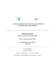
This section of the panel
changes depending on the
Mode toggle choice.
Figure 2
The Edit Settings panel (with ◆ Resolution
toggled)
Table 11 describes the three modes.
Selection
Description
◆ UV Mode
Specifies the facetization as a two-dimensional
grid. This is not recommended since it does not
optimize the number of facets.
You need to specify three fields: Surface U,
Surface V and Boundary.
Boundary is the resolution of the trimmed surface
boundary.
Table 2
8
Modes
CAD Interfaces
CADDS Interface
Selection
Description
◆ Tolerance Mode
Specifies the maximum allowable deviation of the
faceted representation from the actual analytic
surface. This optimizes the number of facets by
creating more where the curvature is high, and
fewer where surfaces are flat.
◆ Edge Length Mode
Specifies the size of the facets, but does not
optimize.
Table 2
Modes (continued)
Table 3 describes the available switches that determine the kind of
geometry that will be edited.
Selection
Description
❏ Curves
If this is switched on, resolution on curves will be
edited according to the current settings.
❏ Surfaces
If this is switched on, resolution on surfaces will be
edited according to the current settings.
❏ Descendents
If this is switched on, resolution on all the
descendents of the selected shape will be edited
according to the current settings.
Table 3
Geometry switches
Skipping Attributes
Toggling ◆ Skip displays four switches, which serve as filters:
❏ Remove Curves
If this is switched on, both discrete and analytic curves will be
skipped during conversion.
❏ Remove Surfaces
If this is switched on, both discrete and analytic surfaces will be
skipped during conversion.
(10/96)
9
Using the CAD Interface Panel
❏ Remove Analytic
If this is switched on, the analytic description of the entities will
be removed after their conversion.
❏ Remove Non-geometry
If this is switched on, entities with no geometry will be skipped
during conversion.
Editing Compaction
Toggling ◆ Compaction provides selections for changing the tree
structure of a specific model by creating a bond between objects.
Compaction can be performed at two levels: at the top node and at the
child level.
Figure 3
◆ Compaction selections
◆ Rigid
Structures the tree of the selected object such that the child
objects are considered to be affixed to the parent object, and are
no longer considered separate entities. If the parent object
moves, its children will move also. In addition, the children are
not permitted to move relative to one another. You must move
the parent to move the children.
10
CAD Interfaces
CADDS Interface
Using rigid compaction increases performance on certain
platforms.
◆ Non-rigid
Structures the tree of the selected object such that the child
objects are considered to be affixed to the parent object, but the
child objects can still move relative to one another.
◆ Permanent Rigid
Structures the object tree such that the all objects, whether parent
or child, are considered to be on one level. This option provides
maximum graphics performance and minimum memory
consumption, but cannot be reversed.
Exporting Models to CADDS
This section describes how to export SILMA software models into
CADDS parts files.
1. Display the CAD Interface panel by selecting Import/Export Model…
from the Modeling pulldown menu.
2. Choose CADDS as the format for export using the Format choice
button.
3. Toggle ◆ Export.
4. Set the path to the directory in which the export file resides.
5. Select the model to be exported from either the Graphics Window or
the Quick Pick Window. Refer to “Supported Entities” on page 12
for the list of export entities supported.
6. Set the filename by double clicking on the text in the File field and
entering the new filename. The default is the path of the selected
model.
7. Click Convert to start the conversion process.
(10/96)
11
Supported Entities
Supported Entities
CADDS to SILMA Software (Importing)
Table 5 describes the supported CADDS entities.
Type
Number
Entity
SILMA software Entity
point
2
point
line
3
rbspline
arc
5
rbspline
conics (302-ellipse,
303-hyperbola, 304-parabola)
6
rbspline
n_spline
12
rbspline
n_surface
14
rbsurf
tabulated cylinder
16
rbsurf
surface of revolution
17
rbsurf
ruled surface
18
rbsurf
plane
88
Table 4
Supported CADDS entities
Table 5 describes the supported miscellaneous n_splines.
Type
Number
Entity
spline (old spline type)
7
rbspline
B-spline
8
rbspline
curve pole (Cpole)
9
rbspline
Table 5
12
SILMA software Entity
Supported miscellaneous n_splines
CAD Interfaces
CADDS Interface
Table 6 describes the supported miscellaneous n_surfaces.
Type
Number
Entity
SILMA software Entity
B-spline surface (Bsurface)
19
rbsurf
surface pole (Spole)
20
rbsurf
Table 6
Supported miscellaneous n_surfaces
Table 7 describes the supported dimensions and tolerance entities that are not
part of CV-DORS.
Type
Number
Entity
SILMA software Entity
feature control symbol
32
gsymbol
linear/ordinate dimension
33
ldimention
angular dimension
34
adimention
radial dimension
35
rdimention
general label
36
glabel
diameter dimension
37
ddimention
Table 7
Supported dimensions and tolerance entities
Table 8 describes the supported miscellaneous entities.
Type
Number
Entity
curve point
10
rctcurve
Vector
22
opoint
Subfigure instance
80
frame
solid or trimmed surface
91
face
face
92
trimsurf
Table 8
(10/96)
SILMA software Entity
Supported miscellaneous entities
13
Supported Entities
SILMA Software to CADDS (Exporting)
CS Entity Type
Table 9
14
CADDS Entity Type
pcurve
nspline
dcurve
lines
single_trace
nspline
dual_trace
nsurface
SILMA software to CADDS (write)
CAD Interfaces
Catia Interface
Catia Interface
Release Notes
Current Version
V 2.3.3
Module
CATIA_INTERFACE_2.3.3
Platform
RS/6000, HP, SGI5
Introduction
The Catia® interface provides two ways to transfer data between Catia and
SILMA software:
■ Catia export files can be translated into SILMA software data.
■ SILMA software data can be translated into Catia export files. The
files generated are of ASCII workstation format.
Both these operations can be performed on any platform on which the interface
is supported. It is not required to have Catia running in order to generate Catia
export files.
The interface has been built to read and install Catia models and CATEXP files
generated by Catia Version 4 Release 1.5 and earlier Catia V3Rx.
The interface uses the Open Data Exchange/CAT Toolkit to read and write
Catia model and project-related information. The entities supported by this
interface are described in “Supported Entities” on page 27. Any entities not
listed in this section are not supported.
(10/96)
15
Introduction
The interface has the capability to read export files (generated by the CATEXP
utility) and convert them into SILMA software .model files. This interface
handles files generated by both mainframe (EBCDIC format) and RS/6000
(ASCII format).
Catia export interface writes SILMA software model data into a Catia export
file. The Catia write interface writes the selected shape tree as a list of details
under the root node. In other words, the shape tree is replaced by the flat list of
details.
The Catia Translator user interface is a user-friendly, menu-driven interface.
“Using the CAD Interface Panel” below provides a detailed description of how
to use SILMA software menus and panels.
By default, Catia model files with the .exp extension are recognized as Catia
files. If a different file extension is desired, you can change the file extension
for the current state by modifying the '<file_extension>' field:
IMPORTANT
Do not change file_extension to model. SILMA
software files use the .model extension, so setting
the catia_file_extension global to model
causes ambiguity.
You should also note that the Catia interface does not
have the ability to read Catia-generated .model files
(even if they are renamed).
NOTE
16
Text commands must be entered at the SIL> prompt. You can
use the SIL> prompt in a shell window by selecting Exit
Menus from the File pulldown menu. To obtain access to the
menus and panels, enter menus(); at the SIL> prompt when
you are finished entering text commands.
CAD Interfaces
Catia Interface
Using the CAD Interface Panel
The CAD Interface panel is displayed by selecting Import/Export Model… from
the Modeling pulldown menu.
List of directories under the
current directory.
This section of the panel changes
depending on the Import/Export
toggle.
Importing files is explained in
“Importing Models” on page 19.
Exporting models is explained in
“Exporting Models” on page 25.
Performs the
conversion.
Figure 4
(10/96)
The CAD Interface panel
17
Using the CAD Interface Panel
The CAD Interface panel selections for the Catia interface are described in
Table 10.
Selection
Description
Format
Specifies the format of the file that will be imported into
SILMA software. The default is Previous State.
Selecting CATIA enables you to translate Catia files into
SILMA software.
◆ Import
Toggle this selection to import Catia models into
SILMA software. See “Importing Models” on page 19.
◆ Export
Toggle this selection to write out a Catia part directly
from SILMA software with selected geometry. See
“Exporting Models” on page 25.
Directory
Sets the path to the directory containing the Catia export
model files.
You can use the list button to select ~cim/projects
or ~cim/users, or use the field to enter any directory
on the system.
The Directories list provides a list of directories under
the current directory. Directories that are not libraries
have two dots (..) after the directory name. Libraries do
not have this symbol.
NOTE A library is a directory that stores data and
information about SILMA software entities.
Selecting a directory from the Directories list makes it
the current directory.
File Extension
Specifies the file extension that will be used to identify
Catia files.
IMPORTANT This field should not be set to model.
SILMA software files use the .model extension, so
setting the File Extension to model causes ambiguity.
Convert
Converts the export files in the conversion queue.
Close
Cancels the settings and dismisses the panel.
Table 10
18
CAD Interface selections
CAD Interfaces
Catia Interface
Importing Models
To import a Catia model into SILMA software, follow these steps:
1. Display the CAD Interface panel by selecting Import/Export Model…
from the Modeling pulldown menu.
2. Choose CATIA as the format for import using the Format choice
button.
3. Toggle ◆ Import.
4. Set the path to the directory in which the export file resides by using
the Current selection and choose the file or files to be imported by
selecting the file or files from the list.
5. Switch on ❏ Add to World if desired. Switching this on installs the
converted model into the current workcell.
6. Switch on ❏ Save to File if desired.
If this is switched off, the converted model will be not be saved.
Switching this on specifies that you would like to save the converted
model. Either the ❏ Use From or Save Dir selections are used to
specify the directory where the converted model will be saved:
selections are used to specify a directory where the
converted model will be saved. These selections are only available
if you have specified that you want to save the file by switching on
❏ Save to File and that you do not want to save the file in the current
directory by switching off ❏ Use From.
Save Dir
Clicking this button displays a list used to select a directory.
You can also enter a directory name in the field.
Switching on ❏ Use From saves the imported file in the current
directory. Switching this off enables you to specify a different
directory using the Save Dir selections. This selection is only
available if you have specified that you want to save the file by
switching on ❏ Save to File.
7. Click Edit Settings… to display the Edit Settings panel and change the
settings as desired. The Edit Settings panel is described in “Editing
the Settings” on page 21.
(10/96)
19
Using the CAD Interface Panel
8. Click Convert to start the conversion process.
NOTE
During conversion, the interface first checks for a
corresponding model file in the directory. If a current model file
is found, the interface installs the model instead of converting
the export file. If the model is not current (i.e., if the export file
has been modified after the model file was generated), the
interface updates the model by performing the conversion.
Importing Large Export Files
When export files consist of a large number of models of considerable
size, SILMA software might not have enough memory to process all of
them. In such cases, selective extraction of models is preferred.
Two globals are introduced to facilitate the selective extraction of
models from an export file. These are
model_lower specifies which model to start at (inclusive)
model_upper specifies which model to stop at (inclusive)
Example
If you wanted to extract the 12th model only, then you would set the
globals as follows:
model_lower := 12;
model_upper := 12;
{ start at 12th model }
{ stop at 12th model }
Similarly, if you wanted to extract all the first 7 models, the globals
should be set as
model_lower := 1;
{ start at the first model }
model_upper := 7;
{ stop at the 7th model }
NOTE
20
Text commands must be entered at the SIL> prompt. You can
use the SIL> prompt in a shell window by selecting
Exit Menus from the File pulldown menu. To obtain access to
the menus and panels, enter menus(); at the SIL> prompt
when you are finished entering text commands.
CAD Interfaces
Catia Interface
The globals are reset every time the state is started. They can be
manually reset by calling the procedure
reset_model_limits();
This sets the globals to default, which is to convert all the models.
If you do not know the number of models in the export file, invoking the
conversion with the default settings prints out the number of models.
Editing the Settings
The Edit Settings panel is displayed by clicking Edit Settings… in the
CAD Interface panel.
This section of the panel
changes depending on the
Mode toggle choice.
Figure 5
(10/96)
The Edit Settings panel (with ◆ Resolution
toggled)
21
Using the CAD Interface Panel
Editing Resolution
Toggling ◆ Resolution enables you to modify segment length or facet
size on parametric models.
Low resolutions (fewer facets) will speed up the graphics for large CAD
models, however the models will look “rough”. High resolution will
make the models look more real, but may slow the graphics of some
platforms. Setting the proper resolution is important as it can achieve a
good balance between performance and appearance.
Table 11 describes the three modes.
Selection
Description
◆ UV Mode
Specifies the facetization as a two-dimensional
grid. This is not recommended since it does not
optimize the number of facets.
You need to specify three fields: Surface U,
Surface V and Boundary.
Boundary is the resolution of the trimmed surface
boundary.
◆ Tolerance Mode
Specifies the maximum allowable deviation of the
faceted representation from the actual analytic
surface. This optimizes the number of facets by
creating more where the curvature is high, and
fewer where surfaces are flat.
◆ Edge Length Mode
Specifies the size of the facets, but does not
optimize.
Table 11
22
Modes
CAD Interfaces
Catia Interface
Table 3 describes the available switches that determine the kind of
geometry that will be edited.
Selection
Description
❏ Curves
If this is switched on, resolution on curves will be
edited according to the current settings.
❏ Surfaces
If this is switched on, resolution on surfaces will be
edited according to the current settings.
❏ Descendents
If this is switched on, resolution on all the
descendents of the selected shape will be edited
according to the current settings.
Table 12
Geometry switches
Skipping Attributes
Toggling ◆ Skip displays four switches, which serve as filters:
❏ Remove Curves
If this is switched on, both discrete and analytic curves will be
skipped during conversion.
❏ Remove Surfaces
If this is switched on, both discrete and analytic surfaces will be
skipped during conversion.
❏ Remove Analytic
If this is switched on, the analytic description of the entities will
be removed after their conversion.
❏ Remove Non-geometry
If this is switched on, entities with no geometry will be skipped
during conversion.
(10/96)
23
Using the CAD Interface Panel
Editing Compaction
Toggling ◆ Compaction provides selections for changing the tree
structure of a specific model by creating a bond between objects.
Compaction can be performed at two levels: at the top node and at the
child level.
Figure 6
◆ Compaction selections
◆ Rigid
Structures the tree of the selected object such that the child
objects are considered to be affixed to the parent object, and are
no longer considered separate entities. If the parent object
moves, its children will move also. In addition, the children are
not permitted to move relative to one another. You must move
the parent to move the children.
Using rigid compaction increases performance on certain
platforms.
◆ Non-rigid
Structures the tree of the selected object such that the child
objects are considered to be affixed to the parent object, but the
child objects can still move relative to one another.
24
CAD Interfaces
Catia Interface
◆ Permanent Rigid
Structures the object tree such that the all objects, whether parent
or child, are considered to be on one level. This option provides
maximum graphics performance and minimum memory
consumption, but cannot be reversed.
Exporting Models
Toggling ◆ Export provides selections for converting SILMA software
models to Catia Export files.
Selects the model to be
converted (if ◆ Model is
toggled).
Specifies the filename of
the converted model.
Figure 7
◆ Export selections
The Catia Export interface writes back a Catia Version 3 export file. The
Catia export files generated by the Export interface can be read back into
SILMA software using the Catia import interface. Only one model at a
time can be written out into an export file.
Wireframe data is converted into cache segments and stored as a bunch
of line segments. Connected curves are stored as composite curves and
disconnected curves are stored as individual line segments.
Solids/surfaces are written out as polyhedral solid/surface data.
Stripped surfaces (no analytical information) cannot be written into
Catia. As the entities written into Catia export file are discrete, their
resolution cannot be altered after exporting. In order to achieve the
(10/96)
25
Using the CAD Interface Panel
desired resolution, the shape tree passed into the export interface should
be pre-processed to that resolution. We recommend you keep the
resolution within reasonable limits because the file size grows
proportionately.
To export a SILMA software model into Catia, follow these steps:
1. Select Import/Export Model… from the Modeling pulldown menu.
2. Choose CATIA as the format of export using the Format choice
button.
3. Toggle ◆ Export.
4. Set the path to the directory in which the export file is written.
5. Select the model to be exported from either the Graphics Window or
the Quick Pick Window. Refer to “Supported Entities” on page 27
for the list of export entities supported.
6. Set the filename by double clicking on the text in the File field and
entering the new filename. The default is the path of the selected
model.
7. Click Convert to start the conversion process.
8. The system will prompt you at the end of the process.
NOTE
26
The Catia interface does not support mirrored entities and
dittos.
CAD Interfaces
Catia Interface
Trouble Shooting
This section describes some of the file-related problems.
ERROR
Incompatible file format.
SOLUTION
This error can be caused by one of the following:
■ The export file being read-in does not conform to
the Catia export file formats. Check if the file is a
valid Catia export file generated by either the
Catia export utility or the SILMA software-Catia
interface.
■ There may be unwanted control characters in the
file. Check if the file is compressed/coded.
ERROR
Error in writing export file.
SOLUTION
This error occurs while exporting a model into Catia.
It can be caused by one of the following:
■ The user does not have permission to write in the
directory the file is being written into.
■ There is not enough space in the directory.
Supported Entities
Table 13 describes the space (3D) entities supported.
Entity
point
Table 13
(10/96)
Type Number SILMA software Entity
1
point shape
Space (3D) entities supported
27
Supported Entities
Entity
Type Number SILMA software Entity
line
2
rctcurve
parametric curve
3
rbspline
plane
4
plsurf
polynomial surface
5
rbsurf
trimmed surface
6
trimsurf
volume
7
trimsurf
3-axis system
8
frame
transformation
9
frame
edge
12
skin
13 (as 6)
surfcurve
trimsurf
polyhedral surface
16
facet set
ditto
28
copy of entity with frame
composite curve
24
pcurvelist
Conics:
circle, ellipse,
parabola, hyperbola
20, 21, 22, 23
circle, ellipse, parabola,
hyperbola
NURBS curve
46 (as 3)
rbspline
NURBS surface
47 (as 5)
rbsurf
Table 13
Space (3D) entities supported (continued)
Table 14 describes the solid entities supported.
Entity
polyhedral solid
17
facet set
exact solid
17
trimsurf
Table 14
28
Type Number SILMA software Entity
Solid entities supported
CAD Interfaces
SLA Interface
SLA Interface
Release Notes
Current Version
V 2.0
Module
SLA_INTERFACE_2.0
Platform
HP700, RS/6000, SGI5, Sun, Solaris
Introduction
The SLA interface provides two ways to transfer data between SLA and SILMA
software:
■ SLA data files can be translated into SILMA software.
■ SILMA software data can be translated into SLAtriangularized .stl format files.
Both operations can be performed on any platforms that support the SLA
interface.
The SLA interface imports SLA files. SLA data is brought across as discrete
facets. Since SLA writes out only facet data, the facets do not contain any
analytical information. The model’s resolution is determined by the resolution
at which the model was written out into the SLA file. Once imported, the
model’s resolution cannot be edited.
(10/96)
29
Using the CAD Interface Panel
Using the CAD Interface Panel
The CAD Interface panel is displayed by selecting Import/Export Model… from
the Modeling pulldown menu.
List of directories under the
current directory.
This section of the panel changes
depending on the Import/Export
toggle.
Importing files is explained in
“Importing Models” on page 19.
Exporting models is explained in
“Exporting Models” on page 25.
Performs the
conversion.
Figure 8
30
The CAD Interface panel
CAD Interfaces
SLA Interface
The CAD Interface panel selections for the SLA interface are described in Table
10.
Selection
Format
Specifies the format of the file that will be imported into
SILMA software. The default is Previous State.
Selecting SLA enables you to translate .stl files into
SILMA software.
◆ Import
Toggle this selection to import SLA models into
SILMA software.
◆ Export
Toggle this selection to write out a .stl part directly
from SILMA software with selected geometry. See
“Exporting Models” on page 25.
Directory
Sets the path to the directory containing the SLA export
model files.
You can use the list button to select ~cim/projects
or ~cim/users, or use the field to enter any directory
on the system.
The Directories list provides a list of directories under
the current directory. Directories that are not libraries
have two dots (..) after the directory name. Libraries do
not have this symbol.
NOTE A library is a directory that stores data and
information about SILMA software entities.
Selecting a directory from the Directories list makes it
the current directory.
File Extension
Specifies the file extension that will be used to identify
SLA files.
Convert
Converts the export files in the conversion queue.
Close
Cancels the settings and dismisses the panel.
Table 15
(10/96)
Description
CAD Interface selections
31
Using the CAD Interface Panel
Importing Models
To import a SLA model into SILMA software, follow these steps:
1. Display the CAD Interface panel by selecting Import/Export Model…
from the Modeling pulldown menu.
2. Choose SLA as the format for import using the Format choice button.
3. Toggle ◆ Import.
4. Set the path to the directory in which the export file resides by using
the Current selection and choose the file or files to be imported by
selecting the file or files from the list.
5. Switch on ❏ Add to World if desired. Switching this on installs the
converted model into the current workcell.
6. Switch on ❏ Save to File if desired.
If this is switched off, the converted model will be not be saved.
Switching this on specifies that you would like to save the converted
model. Either the ❏ Use From or Save Dir selections are used to
specify the directory where the converted model will be saved:
selections are used to specify a directory where the
converted model will be saved. These selections are only available
if you have specified that you want to save the file by switching on
❏ Save to File and that you do not want to save the file in the current
directory by switching off ❏ Use From.
Save Dir
Clicking this button displays a list used to select a directory.
You can also enter a directory name in the field.
Switching on ❏ Use From saves the imported file in the current
directory. Switching this off enables you to specify a different
directory using the Save Dir selections. This selection is only
available if you have specified that you want to save the file by
switching on ❏ Save to File.
32
CAD Interfaces
SLA Interface
7. Click Convert to start the conversion process.
NOTE
During conversion, the interface first checks for a
corresponding model file in the directory. If a current model file
is found, the interface installs the model instead of converting
the export file. If the model is not current (i.e., if the export file
has been modified after the model file was generated), the
interface updates the model by performing the conversion.
Exporting Models
Toggling ◆ provides selections for converting SILMA software models
to SLA Export files.
Selects the model to be
converted (if ◆ Model is
toggled).
Specifies the filename of
the converted model.
Figure 9
◆ Export selections
The export interface looks at all the nodes with cache (display data) and
writes them into the .stl file. Blockc’s are directly written out and
meshes are converted into blockc before they are written. Linesets
(wireframe data) are not supported by SLA.
All geometric entities are exported from SILMA to SLA. The only
except is wireframe data, since SLA does not support it.
(10/96)
33
Notes on Working with SLA Files
Notes on Working with SLA Files
■ Blockc’s are expected to have convex facets. If they do not,
set “force_convex_facets” to TRUE (which is the default)
and re-create their cache. Failure to do this may result in the
facets being incorrect after generation.
■ The exported shape will be created with respect to its current
pose in the current units. Note that SLA files do not store
units. Set the current units to the desired units and, if
necessary, re-attach the pose onto the object before
exporting the shape.
■ As entities written out into the .stl file are discrete, their
resolution cannot be altered after exporting. In order to
achieve the desired resolution in the receiving system, the
shape tree passed into the export interface should be preprocessed to the desired resolution. Because the file size
grows proportionately, you should keep the resolution within
reasonable limits.
34
CAD Interfaces
Pro/ENGINEER Interface
Pro/ENGINEER
Interface
Release Notes
Current Version
Pro/ENGINEER Version
Platform
V 3.0
Rel 17
RS/6000, HP, SGI 5.3, Solaris 5.5
The Pro/ENGINEER® to SILMA software interface converts Pro/ENGINEER
solid model parts and assemblies into SILMA software models and workcells,
respectively. This interface requires the Pro/ENGINEER software to be running
along with SILMA software for the data transfer to be accomplished.
Pro/ENGINEER parts are converted into SILMA software and saved
as .model files. During conversion of Pro/ENGINEER assemblies, individual
parts are stored as .model files and the final assembly is stored as a cell in
SILMA software. Any part or assembly that has been previously converted is
not re-converted.
The interface has been built to transfer Pro/ENGINEER solid model part data
into the SILMA software. The entities supported by this interface are listed in
“Supported Entities” on page 40. The Pro/ENGINEER part to be transferred
should be a solid-model part.
The Pro/ENGINEER interface enables you to bring across geometric tolerance
(GD&T) information along with the geometry of the part or assembly. GD&T
data attached to a part are extracted and stored in their respective classes. All the
GD&T associated with the part are stored under an empty node named GDT
(10/96)
35
Release Notes
under the main part node. GDT node is at the same level as the geometry. By
default, all the GD&T information is made invisible. Users who need visual
access to the information can see it by using the “unhide” panel selections.
CimStation Inspection Users:
NOTE
GD&T information can be used in CimStation Inspection products for
direct code generation. See the “Tolerances” section on page 8-13 of
the CimStation Inspection User’s Manual for more details.
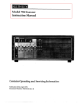
The following illustration depicts the tree structure of an extracted part that has
been imported from Pro/ENGINEER into SILMA software.
PTC_part: part from
Hidden by default
PTC_part
GDT
gdt0
tr0
gdt1
tr1
gdt2
tr2
gdt3
tr3
…
…
Pro/ENGINEER
(empty node)
GDT: empty node that holds
GD&T information
tr*: trim surfaces making the
part geometry
gdt*: GD&T information
associated with ‘part’
If, for instance, gdt0 is perpendicularity, then its class list will be
list(emptyshape, ptc_gdt, perpendicularity, geomtol, shape).
The perpendicularity class contains all the necessary information about the
tolerance like the tol value, datum or datums associated with it, qualifier, etc.
ptc_gdt class will provide the ID of the entity to which the tolerance is
associated.
NOTE
36
Once displayed, the GD&T information is view dependent. The leaders
make sense only when viewed normal to the GDT box. This is the
camera angle at which the part was viewed in Pro/ENGINEER during
the export operation. Since some of the boxes might be enclosed
inside the object, it is best to view them in wireframe mode.
CAD Interfaces
Pro/ENGINEER Interface
GD&T associated with dimensions are displayed along the side of the part in a
stack. This is due to the fact that they do not have leaders associated with them.
NOTE
Datum Reference Planes are not brought across in the current release.
Getting Started
1. To start SILMA software, enter the following at the UNIX prompt:
sspa or ./sspa
The Product Administration panel is displayed.
2. The Pro/ENGINEER to SILMA software interface template is
named proe. Select this product by clicking on proe in the Select
Product to Start
list. Pro/ENGINEER
3. Click Start Product.
4. You will be prompted for the command to start the Pro/ENGINEER
software:
Enter command to start Pro/ENGINEER [return to cancel]:
Enter pro (or whichever command is used to start
Pro/ENGINEER).
Pro/ENGINEER will automatically start the proe template and link
SILMA software to Pro/ENGINEER.
NOTE
If the proe script uses change directory (CD) to start Pro/ENGINEER
from a specific area, SILMA software will not be linked.
To configure the SILMA software side of the converter, you may need to edit
the cim_ptc_config/proe_defaults.sil file. This file contains all the
default settings for the model file being written. The defaults are set to
reasonable values and may not need any modification.
(10/96)
37
Exporting Models
Exporting Models
Following these steps will write out and save a SILMA software model file into
the SILMA software project directory:
1. Start the template following the instructions outlined in the above
section.
2. Create a Pro/ENGINEER solid model part or activate a
Pro/ENGINEER part by selecting the part:
MODE//PART//RETRIEVE/partname.
3. Export the part into a SILMA software model file by selecting
PART//INTERFACES//EXPORT/<SILMA software product>.
The SILMA software project directory into which the model file is written can
be changed by selecting the menu MISC//CHANGE_SIL_DIR. You will be
prompted to enter the new SILMA software export directory. The lib_link
will only be updated if the selected project directory exists. If the selected
directory does not exist, the previous value of lib_link is retained.
A default directory can be set during start-up for the session by modifying the
string lib_link in the cim_ptc_config/proe_defaults.sil file in the
template area:
lib_link := ‘/project/demo’;
NOTE
Text commands must be entered at the SIL> prompt. You can
use the SIL> prompt in a shell window by selecting Exit
Menus from the File pulldown menu. To obtain access to the
menus and panels, enter menus(); at the SIL> prompt when
you are finished entering text commands.
This command changes the save directory to /project/demo/models
for .model files and /project/demo/cells for .cell files.
The converted model or cell file can be installed into any SILMA software state.
38
CAD Interfaces
Pro/ENGINEER Interface
Trouble-Shooting
ERROR
Problems occurring while translating large assemblies.
SOLUTION
Translating large assemblies may require extra swap space. In
most cases, if the system halts due to lack of swap space, the
problem can be overcome by simply re-starting the state, and then
the conversion process. If this procedure does not correct the
problem, you might have to individually convert sub-assemblies
of relatively smaller size and assemble them in SILMA software.
ERROR
Change Silma Directory Error:
SOLUTION
■ Check that the directory specified is not a fictitious directory.
■ Check that the directory specified is not a project directory
(i.e., does not have models and cells directories in it) and
that you have permission to create directories.
ERROR
Error in writing SILMA software model file.
SOLUTION
■ Check if the default directory specified as lib_link in the
file cim_ptc_config/proe_defaults is a valid
project directory.
■ Check that you have permission to write to the specified
project directory.
■ Check that there is enough space in the directory.
(10/96)
Directory not found.
39
Supported Entities
Supported Entities
Faces (Trimmed Surfaces)
Pro/ENGINEER surface types:
• plane
• cylinder
• cone
• torus
• surface of revolution
• tabulated cylinder
• ruled surface
• coons patch
• fillet surface
• spline surface
• b-spline surface
• cylindrical spline surface
Edges (Trimmed Surfaces Boundary Edges)
Pro/ENGINEER curve types:
• line
• arc
• spline
• b-spline
40
CAD Interfaces
Pro/ENGINEER Interface
Supported GD&T Entities
•
•
•
•
•
•
•
(10/96)
angularity
perpendicularity
flatness
line
circularity
parallelism
cylindricity
•
•
•
•
•
•
circular runout
position
surface
concentricity
total runout
straightness
41
Release Notes
VSA Interface
Release Notes
Current Version
V 1.0
Pro/ENGINEER Version
Pro15
Module
VSA_INTERFACE_1.0
Platform
SGI 5, HP 700
The VSA interface is a one-way translator. The interface exports
Pro/ENGINEER parts into SILMA software model files. Unlike the
Pro/ENGINEER interface, this interface has the capability to transfer
Pro/ENGINEER solid model data along with GD&T and related information
into a SILMA software model file. The VSA Interface is directly integrated into
Pro/ENGINEER and will appear as a menu item in the VSA-GDT menus.
This interface needs Pro/ENGINEER to be running for the data transfer to be
accomplished. The interface has been built to transfer Pro/ENGINEER V15
solid model part and GD&T data into SILMA software model files. The entities
supported by this interface are listed in the section “Supported Entities” on
page 40. Any entities not listed are not yet supported.
The VSA Interface uses the VSA-GDT/Pro host interface to build and access
functional feature models. Refer to VSA-GDT/Pro manuals for more details
about the construction of a functional feature model.
42
CAD Interfaces
VSA Interface
The default directory can be changed during a session by selecting ChangeSilDir
from the Misc main menu. You will be prompted to enter the new SILMA
software export directory. The lib_link will only be updated if the selected
project directory exists. If the selected directory does not exist, the previous
value of lib_link is retained.
A default directory can be set during start-up for the session by modifying the
string lib_link in the cim_ptc_config/proe_defaults.sil file in the
template area:
lib_link := ‘/project/demo’;
Text commands must be entered at the SIL> prompt. You can
use the SIL> prompt in a shell window by selecting Exit
Menus from the File pulldown menu. To obtain access to the
menus and panels, enter menus(); at the SIL> prompt when
you are finished entering text commands.
NOTE
This command changes the save directory to /project/demo/models
for .model files and /project/demo/cells for .cell files.
The converted model or cell file can be installed into any SILMA software state.
Getting Started
1. To start SILMA software, enter the following at the UNIX prompt:
sspa or ./sspa
The Product Administration panel is displayed.
2. The Pro/ENGINEER to SILMA software interface product is named
vsa. Select this product by clicking on vsa in the Select Product to
Start
list.
3. Click Start Product.
(10/96)
43
Exporting Models
4. You will be prompted for the command to start the Pro/ENGINEER
software:
Enter command to start Pro/ENGINEER [return to cancel]:
Enter pro (or whichever command is used to start
Pro/ENGINEER).
Pro/ENGINEER will automatically start the vsa template and link
SILMA software to Pro/ENGINEER.
NOTE
If the vsa script uses change directory (CD) to start
Pro/ENGINEER from a specific area, SILMA software will not
be linked.
To configure the SILMA software side of the converter, you may need to edit
the cim_ptc_config/proe_defaults.sil file. This file contains all the
default settings for the model file being written. The defaults are set to
reasonable values and may not need any modification.
Exporting Models
1. Start the template by following the instructions outlined in the
preceding section.
2. Create a Pro/ENGINEER solid model part or activate an existing
one by retrieving it from memory. This can be done by selecting the
menu: MODE//PART//RETRIEVE/partname.
3. Attach tolerance values on the part. This can be done by using the
menu: MODE//PART//SET_UP//GEOM_TOL.
NOTE
Refer to the Pro/ENGINEER documentation for additional
information.
4. Invoke VSA-GDT by selecting the button: MODE//VSA-GDT.
44
CAD Interfaces
VSA Interface
This menu button appears only when a part is present in the session.
5. Create a Functional Feature model out of the current part.
NOTE
Refer to the VSA-GDT manual for information on creating
functional feature models and attaching tolerances to
them.
6. Once all the information has been fed and edited, export the solid
model part into SILMA software by selecting the menu choice:
VSA-GDT//EXPORT SILMA.
The SILMA software model file is created and the model file is written in the
specified SILMA software export directory.
The new model file can now be loaded into the VSA-Inspection product for
further analysis.
Trouble Shooting
ERROR
Tolerance/Feature not exported.
SOLUTION
Check if the tolerance/feature has been recognized by VSA/GDT
and built into the functional feature model. Note that
Pro/ENGINEER features have NO relation to the functional
features created by VSA/GDT. All the features and tolerances
exported are listed in the Transcript Window during conversion.
ERROR
Change Silma Directory Error:
SOLUTION
■ Check that the directory specified is not a fictitious directory.
■ Check that the directory specified is not a project directory
(i.e., does not have models and cells directories in it) and
that you have permission to create directories.
(10/96)
Directory not found.
45
Trouble Shooting
ERROR
Error in writing SILMA software model file.
SOLUTION
■ Check if the default directory specified as lib_link in the
file cim_ptc_config/proe_defaults is a valid
project directory.
■ Check that you have permission to write to the specified
project directory.
■ Check that there is enough space in the directory.
46
CAD Interfaces
Appendix
Importing Large Models
Large CAD models need extra memory to be accommodated in a SILMA
software session. When importing large model files or CAD models, there may
be a need to increase memory. This appendix explains how to do this.
The variables that need to be modified are alloca_stack_size and malloc_max.
For new products, these variables are located in the file
cim/templates/base/lisp.ini
For existing products, these variables are located in the file
cim/templates/<template name>/lisp.ini
If the error message too many objects in putobj—need to increase
alloca_stack_size is displayed at any time, follow these steps:
1. At the end of the appropriate file, add the command
alloca_stack_size = 24000000;
or
alloca_stack_size = 24M;
2. Add malloc_max to the file (it can be added anywhere) by adding
the command
malloc_max = 30000000;
or
malloc_max = 30M;
By increasing the alloca_stack_size from 6000000 to 24000000, you increase
the swap space requirement by 18 MB.
NOTE
(7/96)
Refer to the Installation Guide for information on swap space
requirements for your specific hardware platform.
A-1