1
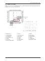
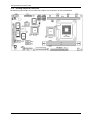
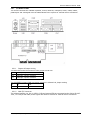
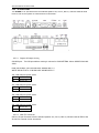
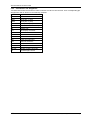
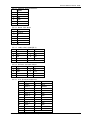
5.2.6.
5.2.7.
5.2.8.
5.2.9.
Expansion Door Assembly............................................................................. 5-47
Riser Card Assembly .................................................................................... 5-47
I/O Module Assembly ................................................................................... 5-48
PC Module Integration.................................................................................. 5-49
5.2.9.1. Motherboard Integration ..................................................................................... 5-49
5.2.9.2. HDD Module Integration ...................................................................................... 5-49
5.2.9.3. Touchscreen Controller Integration........................................................................ 5-49
5.2.9.4. Expansion Door Integration ................................................................................. 5-49
5.2.9.5. Display Module Integration .................................................................................. 5-50
5.2.9.6. Slim CD-ROM/FDD Integration ............................................................................. 5-50
5.2.9.7. Power Supply Integration .................................................................................... 5-51
5.2.9.8. Riser Card Integration......................................................................................... 5-51
5.2.9.9. Inverter Cover Integration ................................................................................... 5-51
5.2.9.10. I/O Cover Integration ...................................................................................... 5-51
5.2.9.11. I/O Cover Integration ...................................................................................... 5-51
6. SYSTEM MOTHERBOARD & I/O BOARDS ............................................................. 6-52
6.1. OP SERIES MOTHERBOARD .................................................................................... 6-54
6.1.1. General Information .................................................................................... 6-54
6.1.2. Specifications.............................................................................................. 6-55
6.1.3. Locating Jumpers & Connectors..................................................................... 6-57
6.1.4. How to Set Jumpers..................................................................................... 6-58
6.1.5. Jumpers & Jumper Setting............................................................................ 6-59
6.1.5.1. JP3: Clear CMOS (JP3) ........................................................................................ 6-61
6.1.6. Connectors & Pin Assignment........................................................................ 6-59
6.1.6.1. ATXP1: ATX Power Connector ............................................................................... 6-63
6.1.6.2. ATXP2: ATX +12V Power Connector....................................................................... 6-60
6.1.6.3. CN1: Touchscreen Power Connector ...................................................................... 6-60
6.1.6.4. PWR1: CD-ROM Power Connector ......................................................................... 6-60
6.1.6.5. INV1: LCD Inverter Connector.............................................................................. 6-60
6.1.6.6. USB1,2: USB Port Connector................................................................................ 6-61
6.1.6.7. LCD1: LCD Connector ......................................................................................... 6-61
6.1.6.8. IDE1: PATA Connector for CD-ROM........................................................................ 6-62
6.1.6.9. SATA1~4: SATA Connector .................................................................................. 6-65
6.1.6.10 COM2 .............................................................................................................. 6-63
6.1.6.11. COM3............................................................................................................ 6-63
6.1.6.12. CD1: CD Audio IN .......................................................................................... 6-63
6.1.6.13. IR1: SIR Connector ......................................................................................... 6-63
6.1.6.14. CN4: Power LED & EXT. KB/MS, USB .................................................................. 6-64
6.1.6.15. IOINF 1: I/O Connector.................................................................................... 6-64
6.1.6.16. EISA1: PCI/ISA Expansion Slot.......................................................................... 6-65
6.1.6.17. FAN 1~3: FAN Connector.................................................................................. 6-67
6.1.6.18. CN3: ATX Power on switch ................................................................................ 6-67
6.1.6.19. RST1: Reset System Connector ......................................................................... 6-70
6.1.6.20. CN2: External LAN Wake-up.............................................................................. 6-70
6.2. OP SERIES I/O BOARDS ....................................................................................... 6-68
6.2.1. I/O Board IO-005 ........................................................................................ 6-69
6.2.1.1. Jumpers & Jumper Setting................................................................................... 6-69
6.2.1.2. CN4: EXT. Connector .......................................................................................... 6-69
6.2.2. IO Board-IO006 .......................................................................................... 6-70
6.2.2.1. Jumpers & Jumper Setting................................................................................... 6-70
6.2.2.2. CN6: EXT. Connector .......................................................................................... 6-70
6.2.3. Connectors & Pin Assignment........................................................................ 6-72
6.2.3.1.
6.2.3.2.
6.2.3.3.
6.2.3.4.
6.2.3.5.
6.2.3.6.
6.2.3.7.
Keyboard: PS/2 KB Connector .............................................................................. 6-73
Mouse: PS/2 Mouse............................................................................................ 6-73
COM1, COM2, COM4 (DB-9)................................................................................. 6-73
DC Power: DC Power Output ............................................................................... 6-73
LPT1: D-SUB-25 Parallel Port ............................................................................... 6-73
CRT: VGA (D-SUB 15 Pin) .................................................................................... 6-74
FDD: External FDD Connector .............................................................................. 6-74