1
Installation and Setup
Front Panel Layout
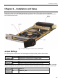
The XVPX-9400 uses four onboard LEDs to indicate the status of PCIe link training. The VPX_PG (VPX back plane to
the system processor), 8114PG (PCIe link train to the PMC sites), XMC_PG (XMC link train to the XMC site), and
RAIDPG (PCIe link train to the LSI RAID Controller) may be solid or blinking if these items are linked.
On the front panel of air-cooled assemblies, there are 8 activity LEDs, one for each drive connection. These LEDs
indicate activity to the drive.
There is also a blue heartbeat LED, which blinks indicating that the firmware is running properly on the LSI RAID
Controller.
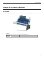
Fig. 3-1 shows an air-cooled front panel
Installation
The XVPX-9400 VPX bus carrier can connect to the VPX bus as a Double Fat Pipe (PCIe x8) device, but is also
supported with a smaller link width.
The path to the XMC site is PCIe x8 from the PCIe switch. The PMC site is PCIx 133MHz 64-bit interface and only
supports 3.3V signaling. The PMC/XMC rear I/O is out the P14 connector, consult the VPX P2 connector for the pin
out of this I/O, Vita 46.9 standard was followed on this design.
Review the Safety Notices section before installing the board. The following notices also apply:
Caution
The XVPX-9400 has been specifically designed for use with 3U VPX backplanes and may not be compatible with
some 6U backplanes. Plugging the board into an unsupported 6U VPX backplane may cause permanent component
damage.
Consult the enclosure documentation to ensure that the XVPX-9400’s power requirements are compatible with those
supplied by the backplane.
Board Keying
The 3U VPX backplane specification requires all backplane slots to have two guide pins: one above the J0
connector and one below the J2 connector. As well as providing correct alignment, these pins are keyed to
prevent cards from being inserted into incorrect backplane slot(s) to avoid electrical incompatibility.
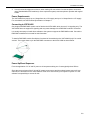
The XVPX-9400 has receptacles for these guide pins (see the Connectors section). By default, these are not
keyed. Please contact the factory to discuss keying requirements.
Installation Notes
1. Keying may dictate the backplane slot(s) into which the XVPX-9425 can be inserted.
2. Air-cooled versions have an ejector handle to ensure that the backplane connectors mate properly with
the backplane. The captive screws at the top and bottom of the front panel allow the XVPX-9425 to be
tightly secured in position, which provides continuity with system chassis ground.
3. Conduction-cooled and REDI versions have screw driven wedge locks at the top and bottom of the board
to provide the necessary mechanical/thermal interface. Correct adjustment requires a calibrated torque
wrench set to between 0.6 and 0.8 Nm.
2-5